vce vxrail appliance - leadkeeper.net · vxrail concepts and architecture 5 © 2016 vce company,...
TRANSCRIPT
VXRAIL CONCEPTS AND ARCHITECTURE
1 © 2016 VCE COMPANY, LLC. ALL RIGHTS RESERVED.
VCE VXRAIL™ APPLIANCE
Hyper-Converged Infrastructure Appliance from EMC® and VMware®
Document H15104 Version 1.0
April, 2016
VXRAIL CONCEPTS AND ARCHITECTURE
2 © 2016 VCE COMPANY, LLC. ALL RIGHTS RESERVED.
Copyright © 2016 EMC Corporation. All rights reserved. EMC believes the information in this publication is accurate as of its publication date. The information is subject to change without notice.
THE INFORMATION IN THIS PUBLICATION IS PROVIDED ―AS IS.‖ EMC CORPORATION MAKES NO REPRESENTATIONS OR WARRANTIES OF ANY KIND WITH RESPECT TO THE INFORMATION IN THIS PUBLICATION, AND SPECIFICALLY DISCLAIMS IMPLIED WARRANTIES OF MERCHANTABILITY OR FITNESS FOR A PARTICULAR PURPOSE.
Use, copying, and distribution of any EMC software described in this publication requires an applicable software license.
EMC2, EMC, VCE, and the EMC logo are registered trademarks or trademarks of EMC Corporation in the United State and other countries. All other trademarks used herein are the property of their respective owners.
For the most up-to-date regulator document for your product line, go to EMC Online Support (https://support.emc.com).
VXRAIL CONCEPTS AND ARCHITECTURE
3 © 2016 VCE COMPANY, LLC. ALL RIGHTS RESERVED.
Table of Contents
Preface
AUDIENCE ......................................................................................................................... 6
RELATED RESOURCES AND DOCUMENTATION ....................................................................... 6
CONTRIBUTORS ................................................................................................................. 7
CONVENTIONS ................................................................................................................... 7
Introduction
DEPLOYMENT TREND TOWARDS CONVERGED INFRASTRUCTURE ............................................. 8
DESIGN TREND TOWARDS SDDCs ........................................................................................ 9
HYPER-CONVERGED INFRASTRUCTURE ............................................................................... 10
VCE Converged Infrastructure Platforms Overview
BLOCK ARCHITECTURE ..................................................................................................... 13
RACK ARCHITECTURE ....................................................................................................... 14
APPLIANCE ARCHITECTURE ............................................................................................... 14
VCE VXRAIL™APPLIANCE PRODUCT PROFILE ....................................................................... 15
VxRail Hardware Architecture
VXRAIL APPLIANCE CLUSTER ............................................................................................. 17
VxRail Node ..................................................................................................................... 17
VxRail Node Storage Disk Drives ........................................................................................ 19
VXRAIL MODELS AND SPECIFICATIONS .............................................................................. 19
Scaling ........................................................................................................................... 20
VxRail Software Architecture
APPLIANCE MANAGEMENT ................................................................................................. 23
VxRail Manager ................................................................................................................ 23
VxRail Manager Extension ................................................................................................. 23
VMWARE VSPHERE ........................................................................................................... 26
VMware vSphere vCenter Server ........................................................................................ 26
vCenter Server Services and Interfaces ................................................................................. 27
PSC Deployment Options ................................................................................................... 27
VMware vSphere ESXi ....................................................................................................... 28
ESXi Overview ................................................................................................................ 28
Communication between vCenter Server and ESXi Hosts ....................................................... 29
Virtual Machines ............................................................................................................... 30
VXRAIL CONCEPTS AND ARCHITECTURE
4 © 2016 VCE COMPANY, LLC. ALL RIGHTS RESERVED.
Virtual Machine Hardware .................................................................................................. 31
Virtual Machine Communication .......................................................................................... 31
Virtual Networking ............................................................................................................ 31
Standard Virtual Switch .................................................................................................... 32
Virtual Distributed Switch .................................................................................................. 33
Migration and VMotion ...................................................................................................... 34
Enhanced vMotion Compatibility .......................................................................................... 35
Storage vMotion .............................................................................................................. 35
vSphere Distributed Resource Scheduler ............................................................................. 36
vSphere High Availability (HA) ........................................................................................... 38
vCenter Server Watchdog .................................................................................................. 40
vSphere Fault Tolerance (FT) ............................................................................................. 41
VIRTUAL SAN .................................................................................................................. 42
Disk Groups ..................................................................................................................... 43
Hybrid and All-Flash Differences ......................................................................................... 44
Read Cache: Basic Function ............................................................................................... 44
Write Cache: Basic Function ............................................................................................... 45
Flash Endurance ............................................................................................................... 45
Virtual SAN’s Impact on Flash Endurance ............................................................................... 45
Client Cache .................................................................................................................... 45
Objects and Components .................................................................................................. 46
Witness ........................................................................................................................ 46
Replicas ........................................................................................................................ 46
Storage Policy Based Management (SPBM) .......................................................................... 47
Dynamic Policy Changes .................................................................................................... 47
Storage Policy Attributes ................................................................................................... 47
I/O Paths and Caching Algorithms ...................................................................................... 50
Read Caching ................................................................................................................. 50
Write Caching ................................................................................................................. 52
Distributed Caching Considerations ...................................................................................... 54
Virtual SAN High Availability and Fault Domains ................................................................... 55
Limitations of Two- and Three-Node Configurations .................................................................. 55
Fault Domain Overview ..................................................................................................... 56
Virtual SAN Stretched Cluster ............................................................................................ 57
Site Locality ................................................................................................................... 58
Networking .................................................................................................................... 59
Stretched-Cluster Heartbeats and Site Bias ............................................................................ 59
vSphere HA settings for Stretched Cluster ............................................................................. 59
Snapshots ....................................................................................................................... 59
How Snapshots Work ....................................................................................................... 60
Managing Snapshots ........................................................................................................ 62
Deduplication and Compression ......................................................................................... 62
Advantages of Data-Reduction Technology ............................................................................. 62
In-line Deduplication and Compression per Disk Group .............................................................. 63
Latency and Resource Consumption ..................................................................................... 64
Enabling Deduplication and Compression ............................................................................... 64
Erasure Coding ................................................................................................................ 64
Enabling Erasure Coding ................................................................................................... 66
Requirements ................................................................................................................. 67
Overhead Issues (RAID-5 and RAID-6) ................................................................................. 67
VXRAIL CONCEPTS AND ARCHITECTURE
5 © 2016 VCE COMPANY, LLC. ALL RIGHTS RESERVED.
Integrated Solutions STORAGE TIERING WITH CLOUDARRAY .............................................................................. 68
INTEGRATED BACKUP AND RECOVERY WITH VSPHERE DATA PROTECTION (VDP) .................... 70
INTEGRATED REPLICATION WITH RECOVERPOINT FOR VIRTUAL MACHINES ........................... 71
Use Case Examples USE CASE: CREATE IT CERTAINTY FOR VIRTUAL DESKTOP INFRASTRUCTURE (VDI) ................ 72
Meeting the Virtualization Challenge for Federal Agencies .................................................. 73
USE CASE: SIMPLIFYING THE DISTRIBUTED ENTERPRISE ENVIRONMENT ............................... 74
Meeting the Distributed Enterprise Challenge for State and Local Agencies ........................... 75
Product Information
PRODUCT SUPPORT .......................................................................................................... 76
EMC PROFESSIONAL SERVICES FOR VXRAIL APPLIANCES ..................................................... 76
VSPHERE ORDERING INFORMATION ................................................................................... 77
WE’D LIKE TO HEAR FROM YOU! ........................................................................................ 77
VXRAIL CONCEPTS AND ARCHITECTURE
6 © 2016 VCE COMPANY, LLC. ALL RIGHTS RESERVED.
Preface
This EMC TechBook provides a thorough conceptual and architectural review of the VCE VxRail™
Appliance. It reviews current trends in the industry that are driving adoption of converged
infrastructure and highlights the pivotal role of VxRail Appliances in today’s modern data center.
As part of an effort to improve and enhance the performance and capabilities of its product lines,
EMC periodically releases revisions of its hardware and software. Therefore, some functions
described in this document may not be supported by all versions of the software or hardware
currently in use. For the most up-to-date information on product features, refer to the product
release notes. If a product does not function as described in this document, please contact your
EMC representative.
AUDIENCE
This TechBook is intended for EMC field personnel, partners, and customers involved in designing, acquiring,
managing, or operating aVxRail Appliance solution.This TechBook may also be useful for Systems Administrators
and EMC Solutions Architects.
RELATED RESOURCES AND DOCUMENTATION
Refer to the following items for related, supplemental documentation, technical papers, and websites.
DRS Web Content at https://www.vmware.com/products/vsphere/features/distributed-switch#sthash.WC5hSHzt.dpuf
EMC CloudArray Product Description Guide: https://www.emc.com/collateral/guide/h13456-cloudarray-pdg.pdf
EMC CloudArray AdministratorGuide: http://uk.emc.com/collateral/TechnicalDocument/docu60786.pdf
An overview of VMware VSAN Caching Algorithmsathttps://www.vmware.com/files/pdf/products/vsan/vmware-virtual-san-caching-whitepaper.pdf
vSphere Resource Management athttp:/www.vmware.com/support/pubs
Virtual SAN 6.2 Stretched Cluster Guideat:http://www.vmware.com/files/pdf/products/vsan/VMware-Virtual-SAN-6.2-Stretched-Cluster-Guide.pdf
Virtual SANSparse—Tech Note for Virtual SAN 6.0 Snapshots at https://www.vmware.com/files/pdf/products/
SAN
vSphere Virtual Machine Administration Guide at https://www.vmware.com/support/pubs/vsphere-esxi-vcenter-server-6-pubs.html
Blogs, web pages, publications, and multimedia content from http://www.hyperconverged.org/
VXRAIL CONCEPTS AND ARCHITECTURE
7 © 2016 VCE COMPANY, LLC. ALL RIGHTS RESERVED.
CONTRIBUTORS
Along with other EMC and VMware engineers, field personnel, and partners, the following individuals have been
contributors to this TechBook:
Flavio Fomin Bill Leslie Arron Lock Joe Vukson Sam Huang Aleksey Lib Violin Zhang Colin Gallagher Megan McMichael Hanoch Eiron Gail Riley Jim Wentworth
CONVENTIONS
EMC uses the following type style conventions in this document.
Normal—Used in running (nonprocedural) text for
Names of interface elements, such as names of windows, dialog boxes, buttons, fields, and menus
Namesofresources,attributes,pools,Booleanexpressions,DQL statements, keywords, clauses, environment variables, functions, and utilities
URLs,pathnames,filenames,directorynames,computer names, links, groups, file systems, and notifications
Bold—Used in running (nonprocedural) text for names of commands, daemons, options, programs, processes,
services, applications, utilities, kernels, notifications, system calls, and man pages.
Italic: Used in all text (including procedures) for
Full titles of publications referenced in text
Emphasis, for example, a new term
Policies and variables
Courier: Used for:
System output, such as an error message or script
URLs, complete paths, filenames, prompts, and syntax when shown outside of running text
VXRAIL CONCEPTS AND ARCHITECTURE
8 © 2016 VCE COMPANY, LLC. ALL RIGHTS RESERVED.
Introduction
The IT infrastructure market is undergoing unprecedented transformation. The most significant transformation is
reflected by two major trends: Adeployment trend toward converged infrastructure and a design trend toward
software-defined data centers (SDDCs). Both are responses to the IT realities of infrastructure clutter, complexity,
and high cost; they represent attempts to simplify IT and reduce the overall cost of infrastructure ownership.
Today’s infrastructure environments are typically comprised of multiple hardware and software products from
multiple vendors, with each product offering a different management interface and requiring different training. Each
product in this type of legacy stack is likely to be grossly overprovisioned, using its own resources (CPU, memory,
and storage) to address the intermittent peak workloads of resident applications. The value of a single shared
resource pool, offered by server virtualization, is still generally limited to the server layer. All other products are
islands of overprovisioned resources that are not shared. Therefore, low utilization of the overall stack results in the
ripple effects of high acquisition, space, and power costs. Too many resources can be wasted in legacy
environments.
DEPLOYMENT TREND TOWARDS CONVERGED INFRASTRUCTURE (CI)
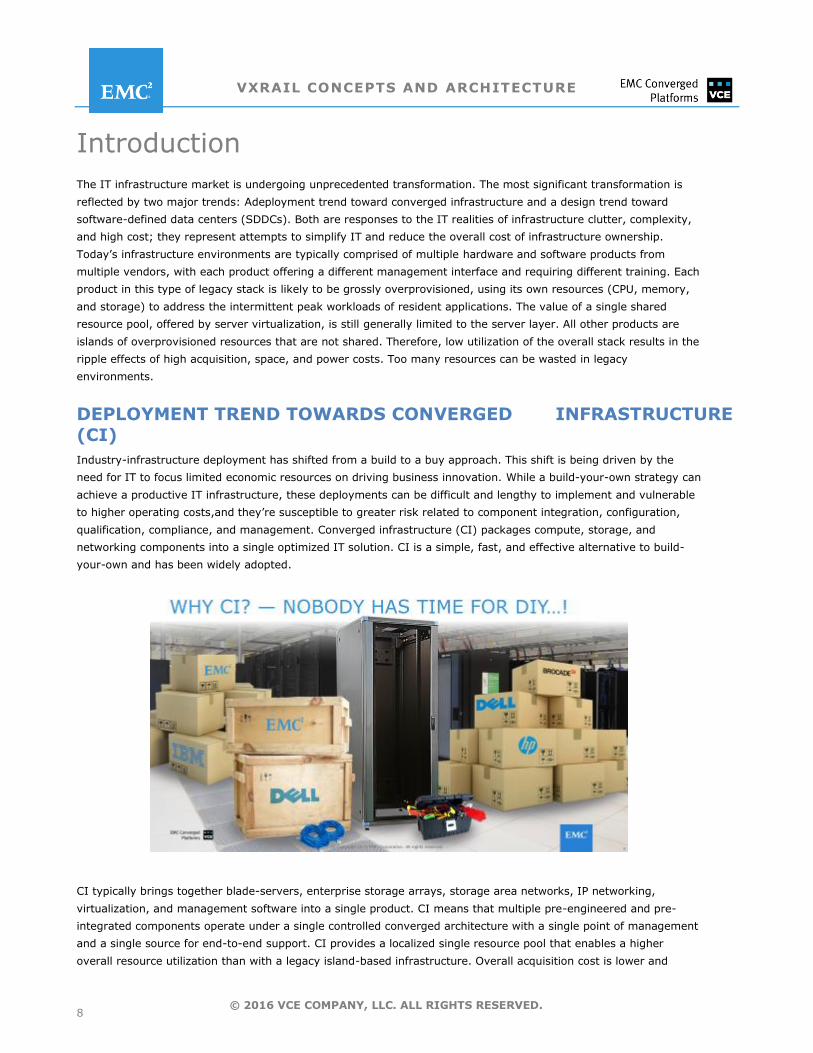
Industry-infrastructure deployment has shifted from a build to a buy approach. This shift is being driven by the
need for IT to focus limited economic resources on driving business innovation. While a build-your-own strategy can
achieve a productive IT infrastructure, these deployments can be difficult and lengthy to implement and vulnerable
to higher operating costs,and they’re susceptible to greater risk related to component integration, configuration,
qualification, compliance, and management. Converged infrastructure (CI) packages compute, storage, and
networking components into a single optimized IT solution. CI is a simple, fast, and effective alternative to build-
your-own and has been widely adopted.
CI typically brings together blade-servers, enterprise storage arrays, storage area networks, IP networking,
virtualization, and management software into a single product. CI means that multiple pre-engineered and pre-
integrated components operate under a single controlled converged architecture with a single point of management
and a single source for end-to-end support. CI provides a localized single resource pool that enables a higher
overall resource utilization than with a legacy island-based infrastructure. Overall acquisition cost is lower and
VXRAIL CONCEPTS AND ARCHITECTURE
9 © 2016 VCE COMPANY, LLC. ALL RIGHTS RESERVED.
management is simplified. In the data center, CI typically has a smaller footprint with less cabling and can be
deployed much faster than traditional infrastructure.
DESIGN TREND TOWARDS
SOFTWARE-DEFINED DATA CENTERS (SDDCs)
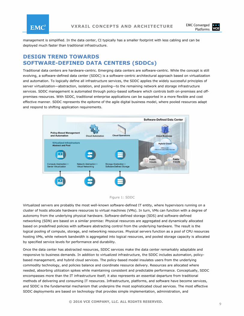
Traditional data centers are hardware-centric. Emerging data centers are software-centric. While the concept is still
evolving, a software-defined data center (SDDC) is a software-centric architectural approach based on virtualization
and automation. To logically define all infrastructure services, the SDDC applies the widely successful principles of
server virtualization—abstraction, isolation, and pooling—to the remaining network and storage infrastructure
services. SDDC management is automated through policy-based software which controls both on-premises and off-
premises resources. With SDDC, traditional enterprise applications can be supported in a more flexible and cost
effective manner. SDDC represents the epitome of the agile digital business model, where pooled resources adapt
and respond to shifting application requirements.
Figure 1: SDDC
Virtualized servers are probably the most well-known software-defined IT entity, where hypervisors running on a
cluster of hosts allocate hardware resources to virtual machines (VMs). In turn, VMs can function with a degree of
autonomy from the underlying physical hardware. Software-defined storage (SDS) and software-defined
networking (SDN) are based on a similar premise: Physical resources are aggregated and dynamically allocated
based on predefined policies with software abstracting control from the underlying hardware. The result is the
logical pooling of compute, storage, and networking resources. Physical servers function as a pool of CPU resources
hosting VMs, while network bandwidth is aggregated into logical resources, and pooled storage capacity is allocated
by specified service levels for performance and durability.
Once the data center has abstracted resources, SDDC services make the data center remarkably adaptable and
responsive to business demands. In addition to virtualized infrastructure, the SDDC includes automation, policy-
based management, and hybrid cloud services. The policy-based model insulates users from the underlying
commodity technology, and policies balance and coordinate resource delivery. Resources are allocated where
needed, absorbing utilization spikes while maintaining consistent and predictable performance. Conceptually, SDDC
encompasses more than the IT infrastructure itself; it also represents an essential departure from traditional
methods of delivering and consuming IT resources. Infrastructure, platforms, and software have become services,
and SDDC is the fundamental mechanism that underpins the most sophisticated cloud services. The most effective
SDDC deployments are based on technology that provides simple implementation, administration, and
VXRAIL CONCEPTS AND ARCHITECTURE
10 © 2016 VCE COMPANY, LLC. ALL RIGHTS RESERVED.
management. This requires an infrastructure solution with an extremely high level of efficiency and serviceability,
such as hyper-converged infrastructure.
HYPER-CONVERGED INFRASTRUCTURE
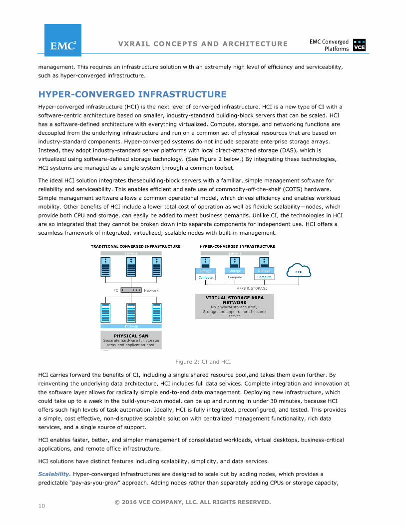
Hyper-converged infrastructure (HCI) is the next level of converged infrastructure. HCI is a new type of CI with a
software-centric architecture based on smaller, industry-standard building-block servers that can be scaled. HCI
has a software-defined architecture with everything virtualized. Compute, storage, and networking functions are
decoupled from the underlying infrastructure and run on a common set of physical resources that are based on
industry-standard components. Hyper-converged systems do not include separate enterprise storage arrays.
Instead, they adopt industry-standard server platforms with local direct-attached storage (DAS), which is
virtualized using software-defined storage technology. (See Figure 2 below.) By integrating these technologies,
HCI systems are managed as a single system through a common toolset.
The ideal HCI solution integrates thesebuilding-block servers with a familiar, simple management software for
reliability and serviceability. This enables efficient and safe use of commodity-off-the-shelf (COTS) hardware.
Simple management software allows a common operational model, which drives efficiency and enables workload
mobility. Other benefits of HCI include a lower total cost of operation as well as flexible scalability—nodes, which
provide both CPU and storage, can easily be added to meet business demands. Unlike CI, the technologies in HCI
are so integrated that they cannot be broken down into separate components for independent use. HCI offers a
seamless framework of integrated, virtualized, scalable nodes with built-in management.
Figure 2: CI and HCI
HCI carries forward the benefits of CI, including a single shared resource pool,and takes them even further. By
reinventing the underlying data architecture, HCI includes full data services. Complete integration and innovation at
the software layer allows for radically simple end-to-end data management. Deploying new infrastructure, which
could take up to a week in the build-your-own model, can be up and running in under 30 minutes, because HCI
offers such high levels of task automation. Ideally, HCI is fully integrated, preconfigured, and tested. This provides
a simple, cost effective, non-disruptive scalable solution with centralized management functionality, rich data
services, and a single source of support.
HCI enables faster, better, and simpler management of consolidated workloads, virtual desktops, business-critical
applications, and remote office infrastructure.
HCI solutions have distinct features including scalability, simplicity, and data services.
Scalability. Hyper-converged infrastructures are designed to scale out by adding nodes, which provides a
predictable ―pay-as-you-grow‖ approach. Adding nodes rather than separately adding CPUs or storage capacity,
VXRAIL CONCEPTS AND ARCHITECTURE
11 © 2016 VCE COMPANY, LLC. ALL RIGHTS RESERVED.
provides linear performance and an elastic infrastructure. Dynamic pooled resources are allocated according to
fluctuating workload requirements. This absorbs application workload spikes and maintains performance
consistency. Mid-sized IT departments or remote enterprise-edge locations, like branch offices, can implement an
inexpensive, entry-level HCI solution, starting small and then easily and non-disruptively scaling both capacity and
performance. HCI integration with public-cloud offerings can also seamlessly and securely expand capacity on
demand and without limits to provide a hybrid-cloud solution.
Simplicity. Hyper-convergence changes the game in terms of management and serviceability. Seamless
integration among HCI elements unifies operations, using familiar consistent interfaces, and simplifies
management. In addition, HCI facilitates simple workload mobility within the entire SDDC. The HCI management
software stack includes applications for monitoring, logging, security and access control, compliance and upgrades,
in addition to configuration utilities for virtual machines, network, and data services. The building-block design
provides a superior implementation model in which all the components have been fully integrated, preconfigured,
and tested, making the system simple to set up, expand, and maintain.
Data Services. HCI provides the same level of mission-critical data services provided by traditional high-end
enterprise storage arrays. Enterprise IT applications are designed with the expectation that the IT infrastructure is
equipped for consistent performance, high availability, and disaster recovery. HCI meets these expectations with
rich data services such as deduplication, compression, replication, and backup and recovery. HCI brings
consumption-based infrastructure economics and flexibility to enterprise IT without compromising on performance,
reliability, or availability.
So when should CI be implemented and when is HCI a better option? The answer depends on the scale and scope
of the infrastructure and the workloads. If the purpose is to support a large number of dense workloads and a
multi-petabyte capacity, then CI is a better option. But for a smallerset of workloads—including the most
demanding loads like databases and OLTP, but at a smaller scale—then HCI is an excellent option. It also is the
appropriate choice for specific departments or remote offices. In short, HCI is ideal for applications that need agility
and need to scale quickly at the lowest cost per unit. HCI is easy to deploy with little expertise. HCI doesn’t replace
CI, but it allows IT to better tier infrastructure for varied application needs. Most IT operations can benefit from a
combination of CI and HCI that can flex to meet the evolving demands of their business.
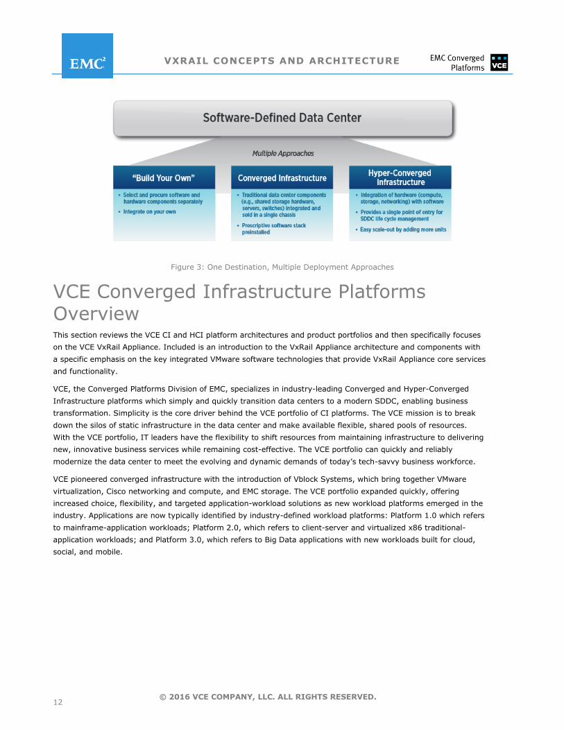
In summary, IT organizations are rapidly evolving into cloud-centric business models where agility, scalability,
security, resource optimization, and SLAs are paramount. The SDDC architecture makes the hybrid cloud possible
by defining a platform common to both private and public clouds. Enterprises have three ways to establish an
SDDC: 1) build their own; 2) use a converged infrastructure; or 3) use a hyper-converged infrastructure. With
seamless integration of the technology stack, both CI and HCI create platforms that allow IT organizations to
efficiently and effectively transition to a modern Software Defined Data Center (SDDC). HCI is the easiest and
fastest way to stand up a fully virtualized software-defined data center (SDDC) environment so IT organizations can
focus on innovation and adding business value.
VXRAIL CONCEPTS AND ARCHITECTURE
12 © 2016 VCE COMPANY, LLC. ALL RIGHTS RESERVED.
Figure 3: One Destination, Multiple Deployment Approaches
VCE Converged Infrastructure Platforms Overview This section reviews the VCE CI and HCI platform architectures and product portfolios and then specifically focuses
on the VCE VxRail Appliance. Included is an introduction to the VxRail Appliance architecture and components with
a specific emphasis on the key integrated VMware software technologies that provide VxRail Appliance core services
and functionality.
VCE, the Converged Platforms Division of EMC, specializes in industry-leading Converged and Hyper-Converged
Infrastructure platforms which simply and quickly transition data centers to a modern SDDC, enabling business
transformation. Simplicity is the core driver behind the VCE portfolio of CI platforms. The VCE mission is to break
down the silos of static infrastructure in the data center and make available flexible, shared pools of resources.
With the VCE portfolio, IT leaders have the flexibility to shift resources from maintaining infrastructure to delivering
new, innovative business services while remaining cost-effective. The VCE portfolio can quickly and reliably
modernize the data center to meet the evolving and dynamic demands of today’s tech-savvy business workforce.
VCE pioneered converged infrastructure with the introduction of Vblock Systems, which bring together VMware
virtualization, Cisco networking and compute, and EMC storage. The VCE portfolio expanded quickly, offering
increased choice, flexibility, and targeted application-workload solutions as new workload platforms emerged in the
industry. Applications are now typically identified by industry-defined workload platforms: Platform 1.0 which refers
to mainframe-application workloads; Platform 2.0, which refers to client-server and virtualized x86 traditional-
application workloads; and Platform 3.0, which refers to Big Data applications with new workloads built for cloud,
social, and mobile.
VXRAIL CONCEPTS AND ARCHITECTURE
13 © 2016 VCE COMPANY, LLC. ALL RIGHTS RESERVED.
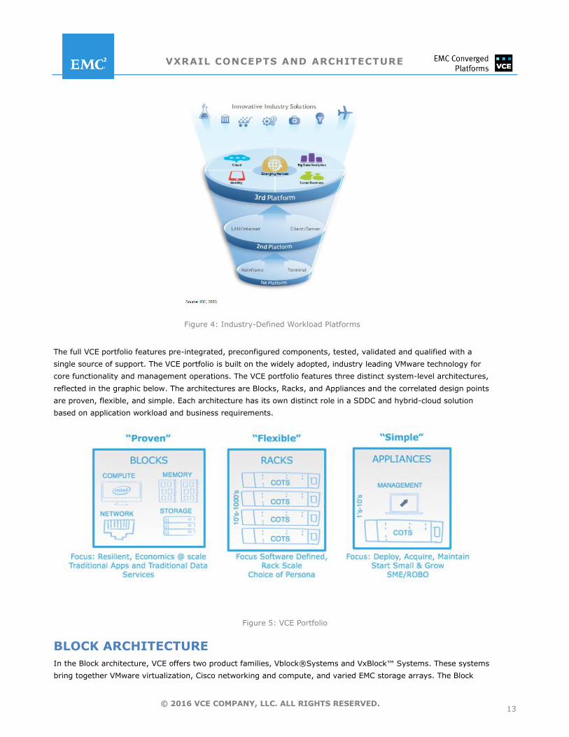
Figure 4: Industry-Defined Workload Platforms
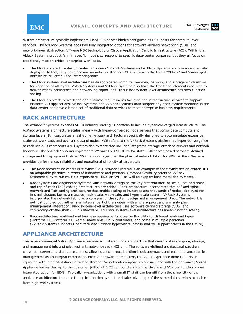
The full VCE portfolio features pre-integrated, preconfigured components, tested, validated and qualified with a
single source of support. The VCE portfolio is built on the widely adopted, industry leading VMware technology for
core functionality and management operations. The VCE portfolio features three distinct system-level architectures,
reflected in the graphic below. The architectures are Blocks, Racks, and Appliances and the correlated design points
are proven, flexible, and simple. Each architecture has its own distinct role in a SDDC and hybrid-cloud solution
based on application workload and business requirements.
Figure 5: VCE Portfolio
BLOCK ARCHITECTURE
In the Block architecture, VCE offers two product families, Vblock®Systems and VxBlock™ Systems. These systems
bring together VMware virtualization, Cisco networking and compute, and varied EMC storage arrays. The Block
VXRAIL CONCEPTS AND ARCHITECTURE
14 © 2016 VCE COMPANY, LLC. ALL RIGHTS RESERVED.
system architecture typically implements Cisco UCS server blades configured as ESXi hosts for compute layer
services. The VxBlock Systems adds two fully integrated options for software-defined networking (SDN) and
network-layer abstraction, VMware NSX technology or Cisco’s Application Centric Infrastructure (ACI). Within the
Vblock Systems product family, specific models correspond to specific data-center purposes, but they all focus on
traditional, mission-critical enterprise workloads.
The Block architecture design center is ―proven.‖ Vblock Systems and VxBlock Systems are proven and widely deployed. In fact, they have become an industry-standard CI system with the terms ―Vblock‖ and ―converged infrastructure‖ often used interchangeably.
The Block system-level architecture has disaggregated compute, memory, network, and storage which allows
for variation at all layers. Vblock Systems and VxBlock Systems also have the traditional elements required to deliver legacy persistence and networking capabilities. This Block system-level architecture has step-function scaling.
The Block architecture workload and business requirements focus on rich infrastructure services to support Platform 2.0 applications. Vblock Systems and VxBlock Systems both support any open-system workload in the data center and have a broad set of traditional data services to meet enterprise business requirements.
RACK ARCHITECTURE
The VxRack™ Systems expands VCE’s industry leading CI portfolio to include hyper-converged infrastructure. The
VxRack Systems architecture scales linearly with hyper-converged node servers that consolidate compute and
storage layers. It incorporates a leaf-spine network architecture specifically designed to accommodate extensive,
scale-out workloads and over a thousand nodes. VCE refers to the VxRack Systems platform as hyper-convergence
at rack scale. It represents a full system deployment that includes integrated storage-attached servers and network
hardware. The VxRack Systems implements VMware EVO SDDC to facilitate ESXi server-based software-defined
storage and to deploy a virtualized NSX network layer over the physical network fabric for SDN. VxRack Systems
provides performance, reliability, and operational simplicity at large scale.
The Rack architecture center is ―flexible.‖ VCE VxRack Systems is an example of the flexible design center. It’s an adaptable platform in terms of itshardware and persona. (Persona flexibility refers to VxRack Systemsability to run multiple hypervisors—ESXi or KVM—as well as support bare-metal deployments.)
Rack systems are engineered systems with network design as the key differentiator. At scale, leaf-and-spine and top-of-rack (ToR) cabling architectures are critical. Rack architecture incorporates the leaf-and-spine network and ToR cabling architecturesthat enable scaling to hundreds and thousands of nodes, deployed not in small clusters but as a massive, rack-scale, web-scale, and hyper-scale system. VxRack Systems incorporates the network fabric as a core part of the system design and management stack. The network is
not just bundled but rather is an integral part of the system with single support and warranty plus management integration. Rack system-level architecture uses software-defined storage (SDS) and commodity-off-the-shelf (COTS) hardware. This rack system-level architecture has linear-function scaling.
Rack-architecture workload and business requirements focus on flexibility for different workload types (Platform 2.0, Platform 3.0, kernel-mode VMs, Linux containers) and come in multiple personas. (VxRackSystems supports OpenStack and VMware hypervisors initially and will support others in the future).
APPLIANCE ARCHITECTURE
The hyper-converged VxRail Appliance features a clustered node architecture that consolidates compute, storage,
and management into a single, resilient, network-ready HCI unit. The software-defined architectural structure
converges server and storage resources, allowing a scale-out, building-block approach, and each appliance carries
management as an integral component. From a hardware perspective, the VxRail Appliance node is a server
equipped with integrated direct-attached storage. No network components are included with the appliance; VxRail
Appliance leaves that up to the customer (although VCE can bundle switch hardware and NSX can function as an
integrated option for SDN). Typically, organizations with a small IT staff can benefit from the simplicity of the
appliance architecture to expedite application deployment and take advantage of the same data services available
from high-end systems.
VXRAIL CONCEPTS AND ARCHITECTURE
15 © 2016 VCE COMPANY, LLC. ALL RIGHTS RESERVED.
The VxRail Appliance architecture design center is ―simple.‖ VxRail Applianceis simple to acquire, deploy, operate, scale, and maintain.
The VxRail Appliance system-level architecture uses SDS and multi-node servers with integrated storage and can leverage whatever network infrastructure is available. Appliance architecture provides low-cost and low-capacity entry points with simple configurations that can easily scale.
Appliance-architecture workload and business requirements focus on simplicity and the ability to start small and grow easily. VDI and productivity applications are examples of the initial workloads deployed in appliances.
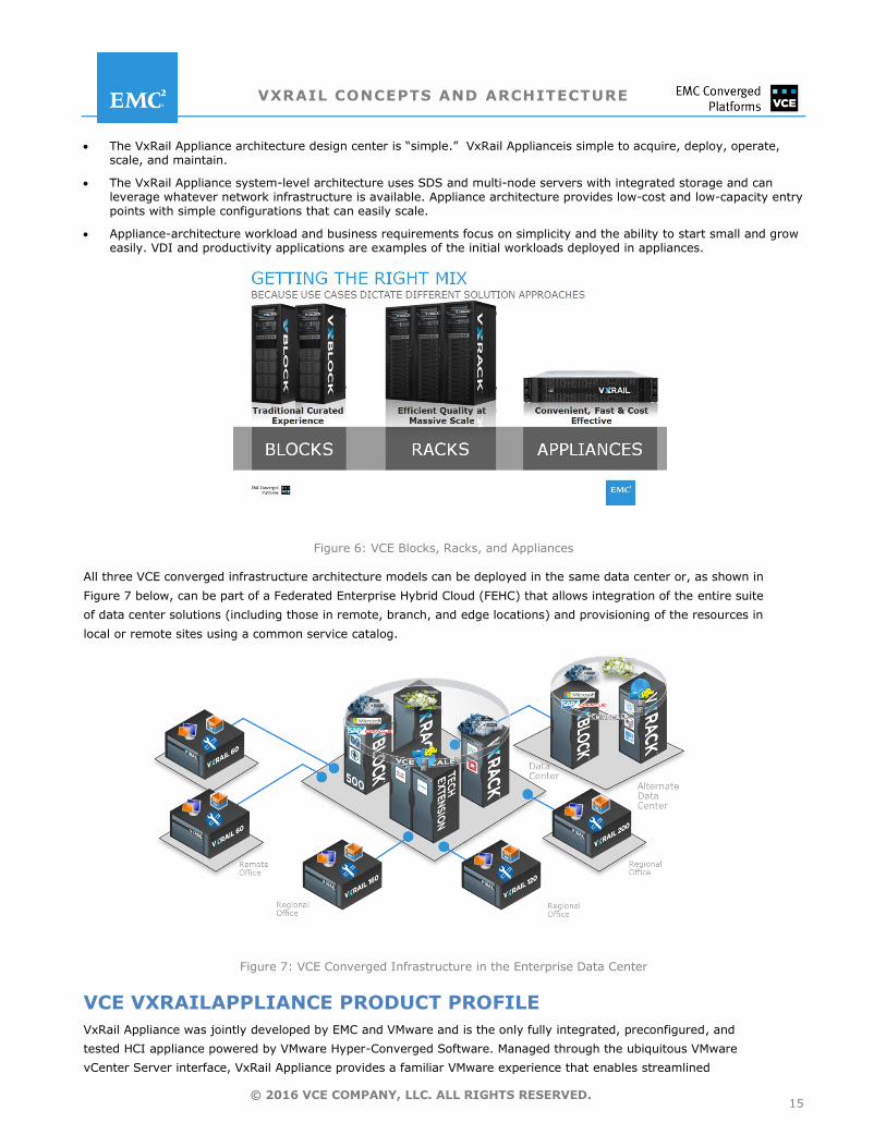
Figure 6: VCE Blocks, Racks, and Appliances
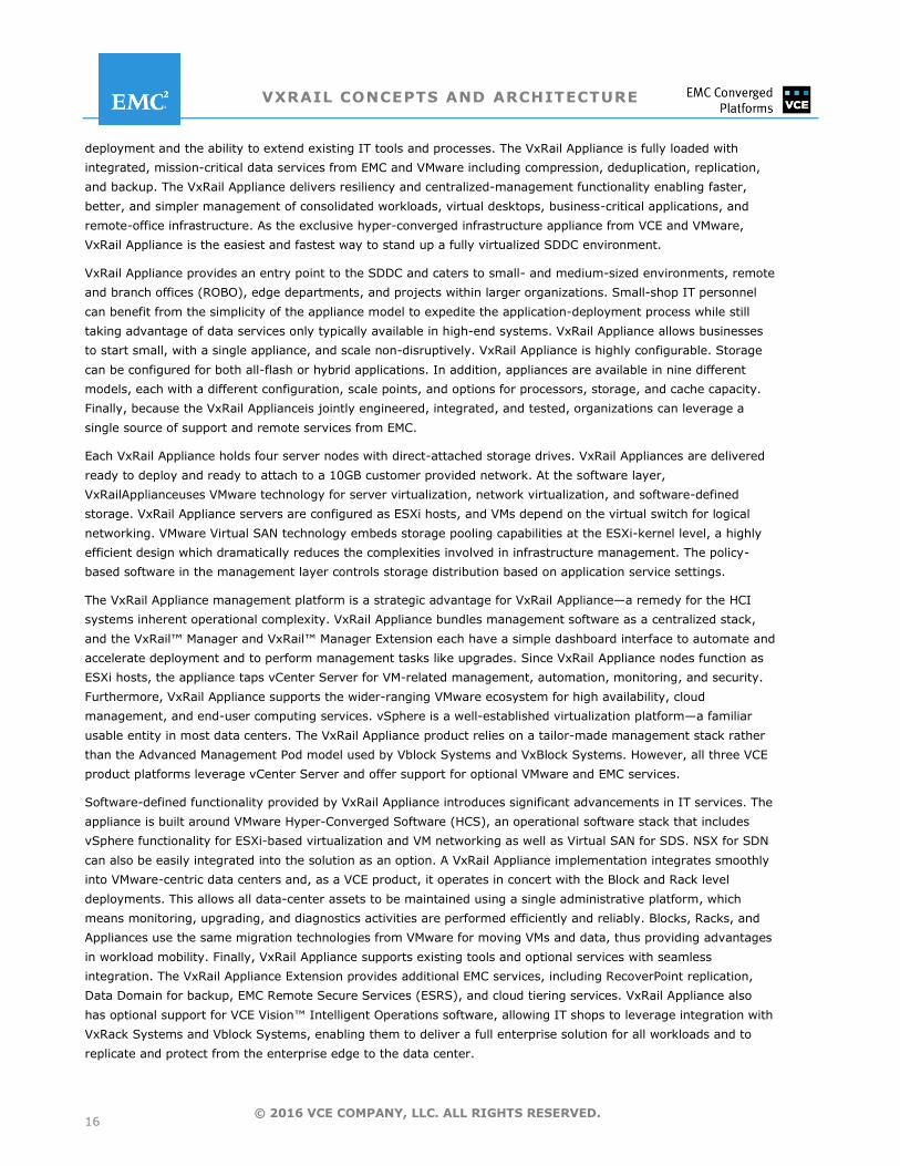
All three VCE converged infrastructure architecture models can be deployed in the same data center or, as shown in
Figure 7 below, can be part of a Federated Enterprise Hybrid Cloud (FEHC) that allows integration of the entire suite
of data center solutions (including those in remote, branch, and edge locations) and provisioning of the resources in
local or remote sites using a common service catalog.
Figure 7: VCE Converged Infrastructure in the Enterprise Data Center
VCE VXRAILAPPLIANCE PRODUCT PROFILE
VxRail Appliance was jointly developed by EMC and VMware and is the only fully integrated, preconfigured, and
tested HCI appliance powered by VMware Hyper-Converged Software. Managed through the ubiquitous VMware
vCenter Server interface, VxRail Appliance provides a familiar VMware experience that enables streamlined
VXRAIL CONCEPTS AND ARCHITECTURE
16 © 2016 VCE COMPANY, LLC. ALL RIGHTS RESERVED.
deployment and the ability to extend existing IT tools and processes. The VxRail Appliance is fully loaded with
integrated, mission-critical data services from EMC and VMware including compression, deduplication, replication,
and backup. The VxRail Appliance delivers resiliency and centralized-management functionality enabling faster,
better, and simpler management of consolidated workloads, virtual desktops, business-critical applications, and
remote-office infrastructure. As the exclusive hyper-converged infrastructure appliance from VCE and VMware,
VxRail Appliance is the easiest and fastest way to stand up a fully virtualized SDDC environment.
VxRail Appliance provides an entry point to the SDDC and caters to small- and medium-sized environments, remote
and branch offices (ROBO), edge departments, and projects within larger organizations. Small-shop IT personnel
can benefit from the simplicity of the appliance model to expedite the application-deployment process while still
taking advantage of data services only typically available in high-end systems. VxRail Appliance allows businesses
to start small, with a single appliance, and scale non-disruptively. VxRail Appliance is highly configurable. Storage
can be configured for both all-flash or hybrid applications. In addition, appliances are available in nine different
models, each with a different configuration, scale points, and options for processors, storage, and cache capacity.
Finally, because the VxRail Applianceis jointly engineered, integrated, and tested, organizations can leverage a
single source of support and remote services from EMC.
Each VxRail Appliance holds four server nodes with direct-attached storage drives. VxRail Appliances are delivered
ready to deploy and ready to attach to a 10GB customer provided network. At the software layer,
VxRailApplianceuses VMware technology for server virtualization, network virtualization, and software-defined
storage. VxRail Appliance servers are configured as ESXi hosts, and VMs depend on the virtual switch for logical
networking. VMware Virtual SAN technology embeds storage pooling capabilities at the ESXi-kernel level, a highly
efficient design which dramatically reduces the complexities involved in infrastructure management. The policy-
based software in the management layer controls storage distribution based on application service settings.
The VxRail Appliance management platform is a strategic advantage for VxRail Appliance—a remedy for the HCI
systems inherent operational complexity. VxRail Appliance bundles management software as a centralized stack,
and the VxRail™ Manager and VxRail™ Manager Extension each have a simple dashboard interface to automate and
accelerate deployment and to perform management tasks like upgrades. Since VxRail Appliance nodes function as
ESXi hosts, the appliance taps vCenter Server for VM-related management, automation, monitoring, and security.
Furthermore, VxRail Appliance supports the wider-ranging VMware ecosystem for high availability, cloud
management, and end-user computing services. vSphere is a well-established virtualization platform—a familiar
usable entity in most data centers. The VxRail Appliance product relies on a tailor-made management stack rather
than the Advanced Management Pod model used by Vblock Systems and VxBlock Systems. However, all three VCE
product platforms leverage vCenter Server and offer support for optional VMware and EMC services.
Software-defined functionality provided by VxRail Appliance introduces significant advancements in IT services. The
appliance is built around VMware Hyper-Converged Software (HCS), an operational software stack that includes
vSphere functionality for ESXi-based virtualization and VM networking as well as Virtual SAN for SDS. NSX for SDN
can also be easily integrated into the solution as an option. A VxRail Appliance implementation integrates smoothly
into VMware-centric data centers and, as a VCE product, it operates in concert with the Block and Rack level
deployments. This allows all data-center assets to be maintained using a single administrative platform, which
means monitoring, upgrading, and diagnostics activities are performed efficiently and reliably. Blocks, Racks, and
Appliances use the same migration technologies from VMware for moving VMs and data, thus providing advantages
in workload mobility. Finally, VxRail Appliance supports existing tools and optional services with seamless
integration. The VxRail Appliance Extension provides additional EMC services, including RecoverPoint replication,
Data Domain for backup, EMC Remote Secure Services (ESRS), and cloud tiering services. VxRail Appliance also
has optional support for VCE Vision™ Intelligent Operations software, allowing IT shops to leverage integration with
VxRack Systems and Vblock Systems, enabling them to deliver a full enterprise solution for all workloads and to
replicate and protect from the enterprise edge to the data center.
VXRAIL CONCEPTS AND ARCHITECTURE
17 © 2016 VCE COMPANY, LLC. ALL RIGHTS RESERVED.
VxRailAppliance Hardware Architecture
The VxRail Appliance family is a proven building block of the Software-Defined Data Center and delivers up to five times
the performance of other hyper-converged appliances. The appliance-based design allows IT centers to scale capacity and
performance non-disruptively, so they can start small and grow incrementally with minimal up-front planning.
VxRailAppliance configurations can start with as fewas 200 virtual machines (VMs) and scale to thousands. The VxRail
Appliancearchitecture enables a predictable pay-as-you-grow approach that aligns to changing business goals and user
demand.
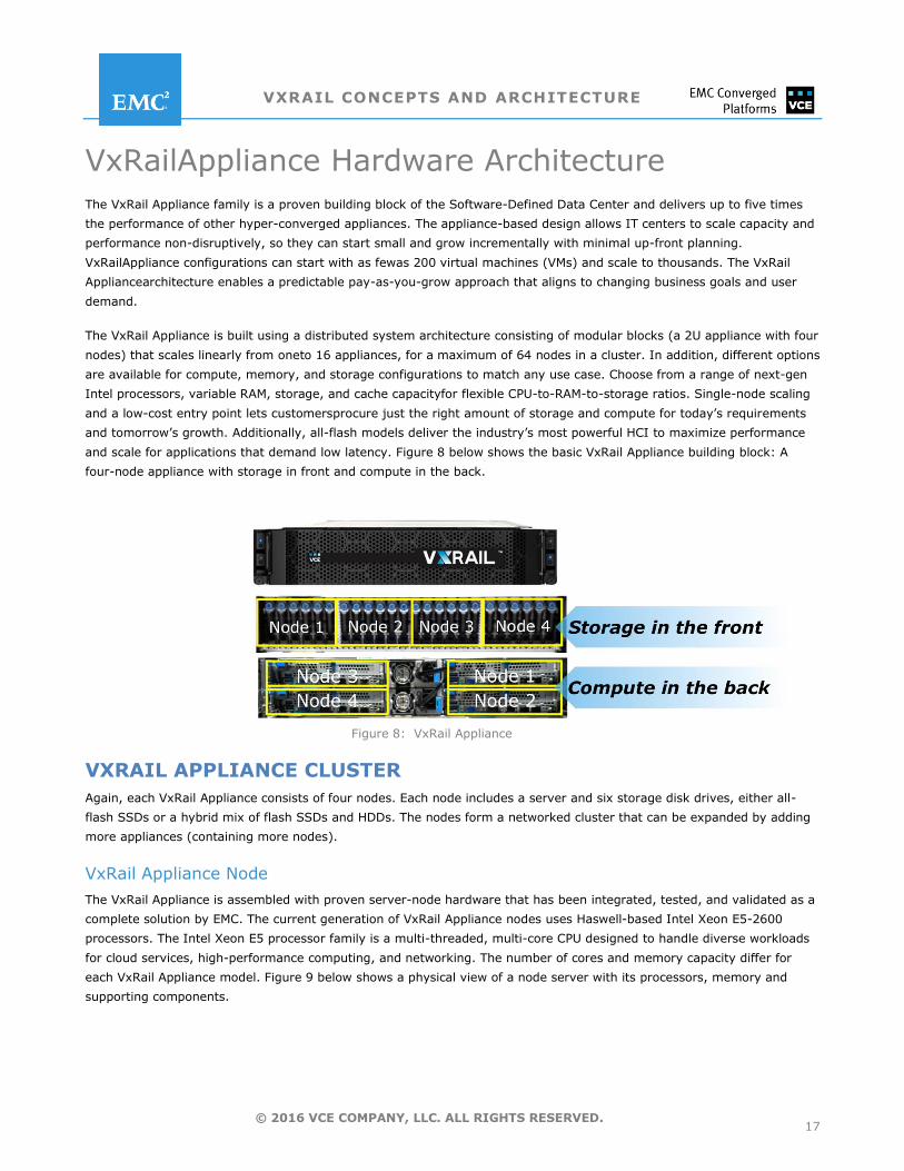
The VxRail Appliance is built using a distributed system architecture consisting of modular blocks (a 2U appliance with four
nodes) that scales linearly from oneto 16 appliances, for a maximum of 64 nodes in a cluster. In addition, different options
are available for compute, memory, and storage configurations to match any use case. Choose from a range of next-gen
Intel processors, variable RAM, storage, and cache capacityfor flexible CPU-to-RAM-to-storage ratios. Single-node scaling
and a low-cost entry point lets customersprocure just the right amount of storage and compute for today’s requirements
and tomorrow’s growth. Additionally, all-flash models deliver the industry’s most powerful HCI to maximize performance
and scale for applications that demand low latency. Figure 8 below shows the basic VxRail Appliance building block: A
four-node appliance with storage in front and compute in the back.
Figure 8: VxRail Appliance
VXRAIL APPLIANCE CLUSTER
Again, each VxRail Appliance consists of four nodes. Each node includes a server and six storage disk drives, either all-
flash SSDs or a hybrid mix of flash SSDs and HDDs. The nodes form a networked cluster that can be expanded by adding
more appliances (containing more nodes).
VxRail Appliance Node
The VxRail Appliance is assembled with proven server-node hardware that has been integrated, tested, and validated as a
complete solution by EMC. The current generation of VxRail Appliance nodes uses Haswell-based Intel Xeon E5-2600
processors. The Intel Xeon E5 processor family is a multi-threaded, multi-core CPU designed to handle diverse workloads
for cloud services, high-performance computing, and networking. The number of cores and memory capacity differ for
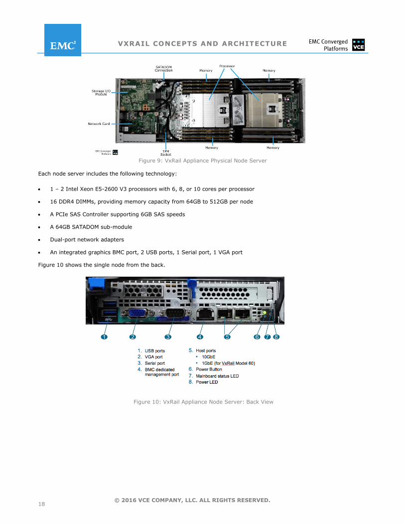
each VxRail Appliance model. Figure 9 below shows a physical view of a node server with its processors, memory and
supporting components.
VXRAIL CONCEPTS AND ARCHITECTURE
18 © 2016 VCE COMPANY, LLC. ALL RIGHTS RESERVED.
Figure 9: VxRail Appliance Physical Node Server
Each node server includes the following technology:
1 – 2 Intel Xeon E5-2600 V3 processors with 6, 8, or 10 cores per processor
16 DDR4 DIMMs, providing memory capacity from 64GB to 512GB per node
A PCIe SAS Controller supporting 6GB SAS speeds
A 64GB SATADOM sub-module
Dual-port network adapters
An integrated graphics BMC port, 2 USB ports, 1 Serial port, 1 VGA port
Figure 10 shows the single node from the back.
Figure 10: VxRail Appliance Node Server: Back View
VXRAIL CONCEPTS AND ARCHITECTURE
19 © 2016 VCE COMPANY, LLC. ALL RIGHTS RESERVED.
VxRail Appliance Node Storage Disk Drives
Storage capacity for the VxRail Appliance is provided by disk drives that have been integrated, tested, and validated by
EMC. 2.5‖ form-factor Solid State Disks (SDD) and mechanical Hard Disk Drives (HDD) are managed in logical groups.
Each group has up to six disk drives and each node has one disk group.Disk groups are configured in two ways:
Hybrid configurations, which contain a single SDD flash-based disk for caching (the caching-tier) and multiple HDD
disks for capacity (the capacity-tier)
All-flash configurations, which contain all SDD flash based disk drives
The flash drives used for caching and capacity have different endurance levels. Endurance level refers to the number of
times that an entire flash disk can be written every day for a five-year period before it has to be replaced. A higher-
endurance SSD is used for caching than for capacity. Currently, the caching tier uses 200GB, 400GB, and 800GB flash
disks, and the capacity tier uses either 3.84TB flash SSDs, 1.2TB HDDs, or 2TB HDDs. All VxRail Appliance disk
configurations use a carefully designed cache-to-capacity ratio to ensure consistent performance.
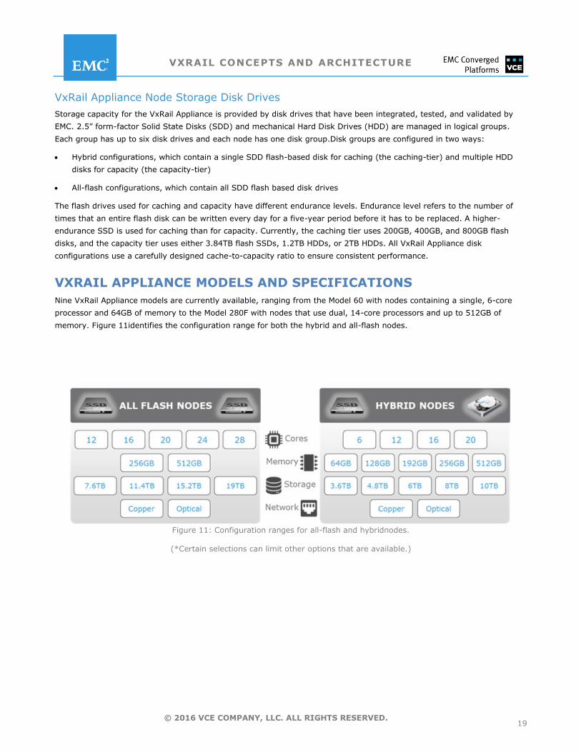
VXRAIL APPLIANCE MODELS AND SPECIFICATIONS
Nine VxRail Appliance models are currently available, ranging from the Model 60 with nodes containing a single, 6-core
processor and 64GB of memory to the Model 280F with nodes that use dual, 14-core processors and up to 512GB of
memory. Figure 11identifies the configuration range for both the hybrid and all-flash nodes.
Figure 11: Configuration ranges for all-flash and hybridnodes.
(*Certain selections can limit other options that are available.)
VXRAIL CONCEPTS AND ARCHITECTURE
20 © 2016 VCE COMPANY, LLC. ALL RIGHTS RESERVED.
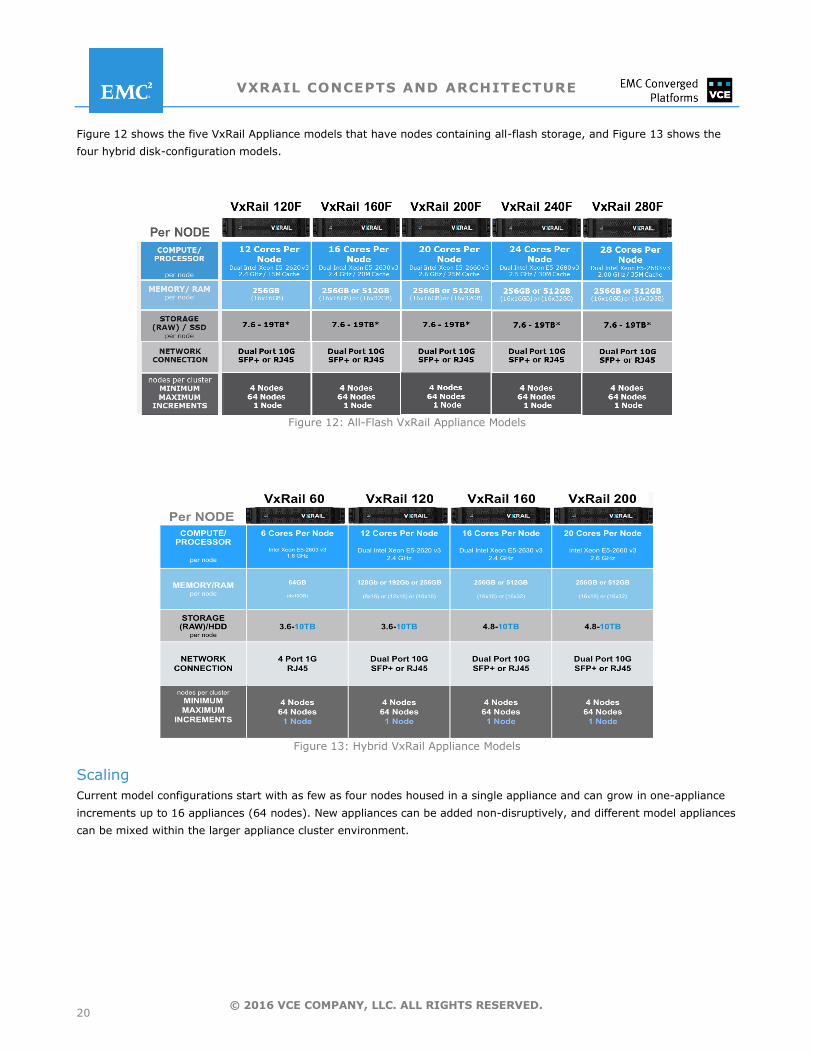
Figure 12 shows the five VxRail Appliance models that have nodes containing all-flash storage, and Figure 13 shows the
four hybrid disk-configuration models.
Figure 12: All-Flash VxRail Appliance Models
Figure 13: Hybrid VxRail Appliance Models
Scaling
Current model configurations start with as few as four nodes housed in a single appliance and can grow in one-appliance
increments up to 16 appliances (64 nodes). New appliances can be added non-disruptively, and different model appliances
can be mixed within the larger appliance cluster environment.
VXRAIL CONCEPTS AND ARCHITECTURE
21 © 2016 VCE COMPANY, LLC. ALL RIGHTS RESERVED.
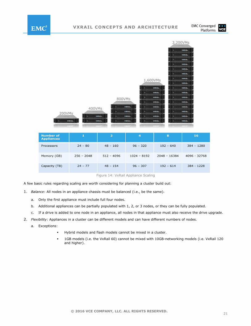
Figure 14: VxRail Appliance Scaling
A few basic rules regarding scaling are worth considering for planning a cluster build out:
1. Balance: All nodes in an appliance chassis must be balanced (i.e., be the same).
a. Only the first appliance must include full four nodes.
b. Additional appliances can be partially populated with 1, 2, or 3 nodes, or they can be fully populated.
c. If a drive is added to one node in an appliance, all nodes in that appliance must also receive the drive upgrade.
2. Flexibility: Appliances in a cluster can be different models and can have different numbers of nodes.
a. Exceptions:
Hybrid models and flash models cannot be mixed in a cluster.
1GB models (i.e. the VxRail 60) cannot be mixed with 10GB-networking models (i.e. VxRail 120 and higher).
VXRAIL CONCEPTS AND ARCHITECTURE
22 © 2016 VCE COMPANY, LLC. ALL RIGHTS RESERVED.
VxRail Appliance Software Architecture
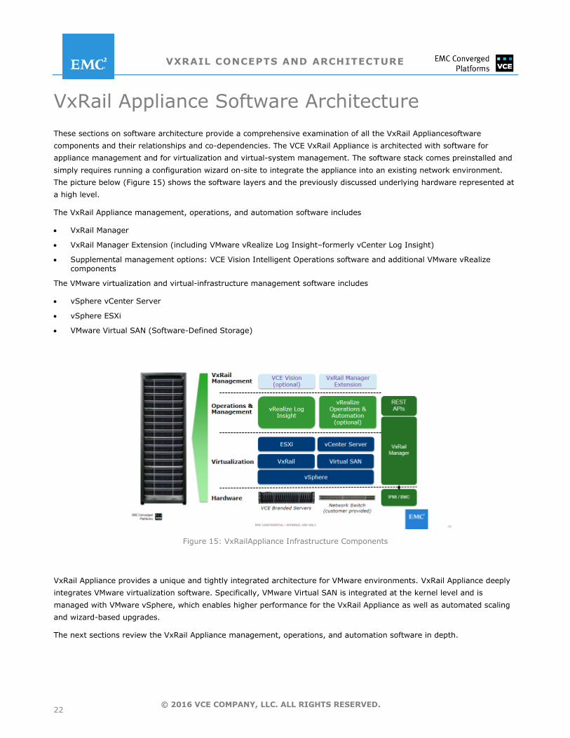
These sections on software architecture provide a comprehensive examination of all the VxRail Appliancesoftware
components and their relationships and co-dependencies. The VCE VxRail Appliance is architected with software for
appliance management and for virtualization and virtual-system management. The software stack comes preinstalled and
simply requires running a configuration wizard on-site to integrate the appliance into an existing network environment.
The picture below (Figure 15) shows the software layers and the previously discussed underlying hardware represented at
a high level.
The VxRail Appliance management, operations, and automation software includes
VxRail Manager
VxRail Manager Extension (including VMware vRealize Log Insight–formerly vCenter Log Insight)
Supplemental management options: VCE Vision Intelligent Operations software and additional VMware vRealize components
The VMware virtualization and virtual-infrastructure management software includes
vSphere vCenter Server
vSphere ESXi
VMware Virtual SAN (Software-Defined Storage)
Figure 15: VxRailAppliance Infrastructure Components
VxRail Appliance provides a unique and tightly integrated architecture for VMware environments. VxRail Appliance deeply
integrates VMware virtualization software. Specifically, VMware Virtual SAN is integrated at the kernel level and is
managed with VMware vSphere, which enables higher performance for the VxRail Appliance as well as automated scaling
and wizard-based upgrades.
The next sections review the VxRail Appliance management, operations, and automation software in depth.
VXRAIL CONCEPTS AND ARCHITECTURE
23 © 2016 VCE COMPANY, LLC. ALL RIGHTS RESERVED.
APPLIANCE MANAGEMENT
VxRail™ Manager
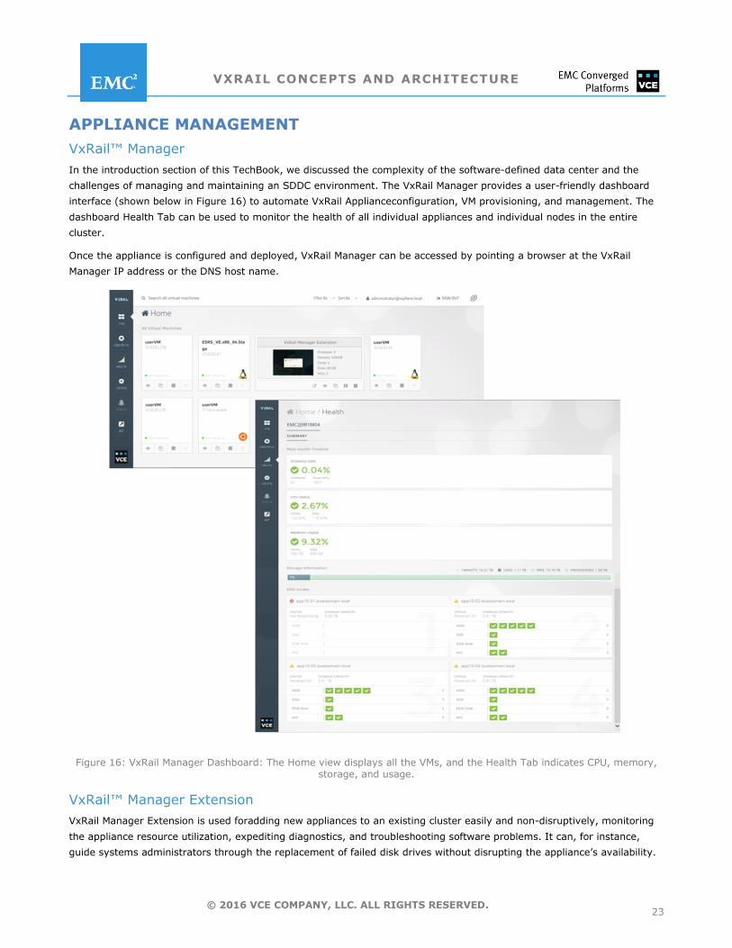
In the introduction section of this TechBook, we discussed the complexity of the software-defined data center and the
challenges of managing and maintaining an SDDC environment. The VxRail Manager provides a user-friendly dashboard
interface (shown below in Figure 16) to automate VxRail Applianceconfiguration, VM provisioning, and management. The
dashboard Health Tab can be used to monitor the health of all individual appliances and individual nodes in the entire
cluster.
Once the appliance is configured and deployed, VxRail Manager can be accessed by pointing a browser at the VxRail
Manager IP address or the DNS host name.
Figure 16: VxRail Manager Dashboard: The Home view displays all the VMs, and the Health Tab indicates CPU, memory, storage, and usage.
VxRail™ Manager Extension
VxRail Manager Extension is used foradding new appliances to an existing cluster easily and non-disruptively, monitoring
the appliance resource utilization, expediting diagnostics, and troubleshooting software problems. It can, for instance,
guide systems administrators through the replacement of failed disk drives without disrupting the appliance’s availability.
VXRAIL CONCEPTS AND ARCHITECTURE
24 © 2016 VCE COMPANY, LLC. ALL RIGHTS RESERVED.
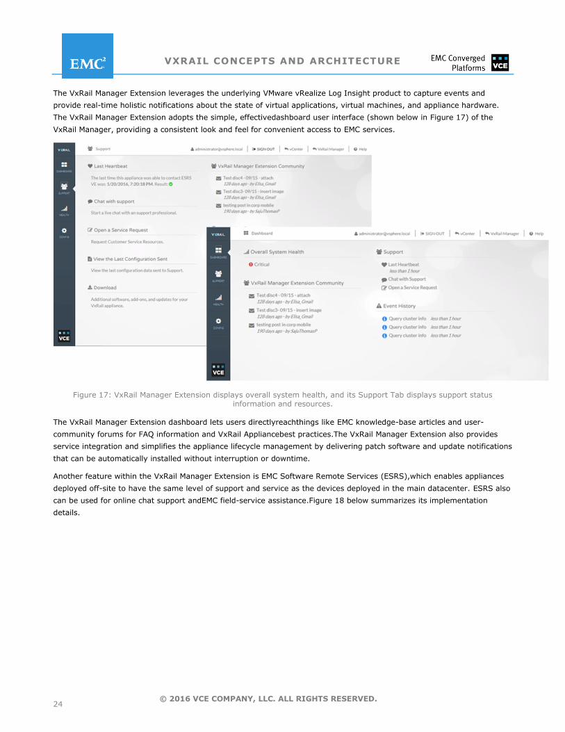
The VxRail Manager Extension leverages the underlying VMware vRealize Log Insight product to capture events and
provide real-time holistic notifications about the state of virtual applications, virtual machines, and appliance hardware.
The VxRail Manager Extension adopts the simple, effectivedashboard user interface (shown below in Figure 17) of the
VxRail Manager, providing a consistent look and feel for convenient access to EMC services.
Figure 17: VxRail Manager Extension displays overall system health, and its Support Tab displays support status information and resources.
The VxRail Manager Extension dashboard lets users directlyreachthings like EMC knowledge-base articles and user-
community forums for FAQ information and VxRail Appliancebest practices.The VxRail Manager Extension also provides
service integration and simplifies the appliance lifecycle management by delivering patch software and update notifications
that can be automatically installed without interruption or downtime.
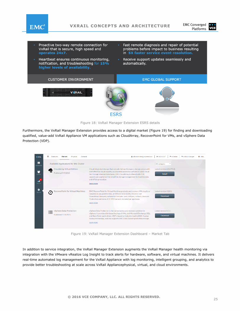
Another feature within the VxRail Manager Extension is EMC Software Remote Services (ESRS),which enables appliances
deployed off-site to have the same level of support and service as the devices deployed in the main datacenter. ESRS also
can be used for online chat support andEMC field-service assistance.Figure 18 below summarizes its implementation
details.
VXRAIL CONCEPTS AND ARCHITECTURE
25 © 2016 VCE COMPANY, LLC. ALL RIGHTS RESERVED.
Figure 18: VxRail Manager Extension ESRS details
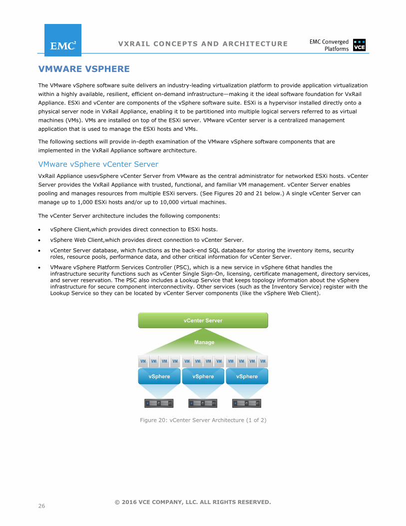
Furthermore, the VxRail Manager Extension provides access to a digital market (Figure 19) for finding and downloading
qualified, value-add VxRail Appliance VM applications such as CloudArray, RecoverPoint for VMs, and vSphere Data
Protection (VDP).
Figure 19: VxRail Manager Extension Dashboard – Market Tab
In addition to service integration, the VxRail Manager Extension augments the VxRail Manager health monitoring via
integration with the VMware vRealize Log Insight to track alerts for hardware, software, and virtual machines. It delivers
real-time automated log management for the VxRail Appliance with log monitoring, intelligent grouping, and analytics to
provide better troubleshooting at scale across VxRail Appliancephysical, virtual, and cloud environments.
VXRAIL CONCEPTS AND ARCHITECTURE
26 © 2016 VCE COMPANY, LLC. ALL RIGHTS RESERVED.
VMWARE VSPHERE
The VMware vSphere software suite delivers an industry-leading virtualization platform to provide application virtualization
within a highly available, resilient, efficient on-demand infrastructure—making it the ideal software foundation for VxRail
Appliance. ESXi and vCenter are components of the vSphere software suite. ESXi is a hypervisor installed directly onto a
physical server node in VxRail Appliance, enabling it to be partitioned into multiple logical servers referred to as virtual
machines (VMs). VMs are installed on top of the ESXi server. VMware vCenter server is a centralized management
application that is used to manage the ESXi hosts and VMs.
The following sections will provide in-depth examination of the VMware vSphere software components that are
implemented in the VxRail Appliance software architecture.
VMware vSphere vCenter Server
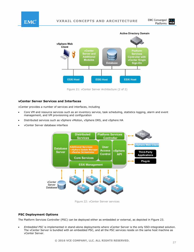
VxRail Appliance usesvSphere vCenter Server from VMware as the central administrator for networked ESXi hosts. vCenter
Server provides the VxRail Appliance with trusted, functional, and familiar VM management. vCenter Server enables
pooling and manages resources from multiple ESXi servers. (See Figures 20 and 21 below.) A single vCenter Server can
manage up to 1,000 ESXi hosts and/or up to 10,000 virtual machines.
The vCenter Server architecture includes the following components:
vSphere Client,which provides direct connection to ESXi hosts.
vSphere Web Client,which provides direct connection to vCenter Server.
vCenter Server database, which functions as the back-end SQL database for storing the inventory items, security roles, resource pools, performance data, and other critical information for vCenter Server.
VMware vSphere Platform Services Controller (PSC), which is a new service in vSphere 6that handles the infrastructure security functions such as vCenter Single Sign-On, licensing, certificate management, directory services, and server reservation. The PSC also includes a Lookup Service that keeps topology information about the vSphere infrastructure for secure component interconnectivity. Other services (such as the Inventory Service) register with the Lookup Service so they can be located by vCenter Server components (like the vSphere Web Client).
Figure 20: vCenter Server Architecture (1 of 2)
VXRAIL CONCEPTS AND ARCHITECTURE
27 © 2016 VCE COMPANY, LLC. ALL RIGHTS RESERVED.
Figure 21: vCenter Server Architecture (2 of 2)
vCenter Server Services and Interfaces
vCenter provides a number of services and interfaces, including
Core VM and resource services such as an inventory service, task scheduling, statistics logging, alarm and event management, and VM provisioning and configuration
Distributed services such as vSphere vMotion, vSphere DRS, and vSphere HA
vCenter Server database interface
Figure 22: vCenter Server services
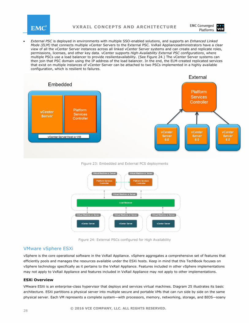
PSC Deployment Options
The Platform Services Controller (PSC) can be deployed either as embedded or external, as depicted in Figure 23.
Embedded PSC is implemented in stand-alone deployments where vCenter Server is the only SSO-integrated solution. The vCenter Server is bundled with an embedded PSC, and all the PSC services reside on the same host machine as vCenter Server.
VXRAIL CONCEPTS AND ARCHITECTURE
28 © 2016 VCE COMPANY, LLC. ALL RIGHTS RESERVED.
External PSC is deployed in environments with multiple SSO-enabled solutions, and supports an Enhanced Linked Mode (ELM) that connects multiple vCenter Servers to the External PSC. VxRail Applianceadministrators have a clear view of all the vCenter Server instances across all linked vCenter Server systems and can create and replicate roles, permissions, licenses, and other key data. vCenter supports High-Availability External PSC configurations, where multiple PSCs use a load balancer to provide resilientavailability. (See Figure 24.) The vCenter Server systems can then join that PSC domain using the IP address of the load balancer. In the end, the ELM-created replicated services that exist on multiple instances of vCenter Server can be attached to two PSCs implemented in a highly available configuration, which is resilient to failures.
Figure 23: Embedded and External PCS deployments
Figure 24: External PSCs configured for High Availability
VMware vSphere ESXi
vSphere is the core operational software in the VxRail Appliance. vSphere aggregates a comprehensive set of features that
efficiently pools and manages the resources available under the ESXi hosts. Keep in mind that this TechBook focuses on
vSphere technology specifically as it pertains to the VxRail Appliance. Features included in other vSphere implementations
may not apply to VxRail Appliance and features included in VxRail Appliance may not apply to other implementations.
ESXi Overview
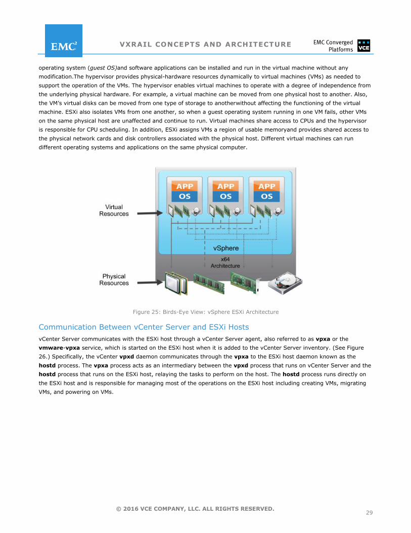
VMware ESXi is an enterprise-class hypervisor that deploys and services virtual machines. Diagram 25 illustrates its basic
architecture. ESXi partitions a physical server into multiple secure and portable VMs that can run side by side on the same
physical server. Each VM represents a complete system—with processors, memory, networking, storage, and BIOS—soany
VXRAIL CONCEPTS AND ARCHITECTURE
29 © 2016 VCE COMPANY, LLC. ALL RIGHTS RESERVED.
operating system (guest OS)and software applications can be installed and run in the virtual machine without any
modification.The hypervisor provides physical-hardware resources dynamically to virtual machines (VMs) as needed to
support the operation of the VMs. The hypervisor enables virtual machines to operate with a degree of independence from
the underlying physical hardware. For example, a virtual machine can be moved from one physical host to another. Also,
the VM’s virtual disks can be moved from one type of storage to anotherwithout affecting the functioning of the virtual
machine. ESXi also isolates VMs from one another, so when a guest operating system running in one VM fails, other VMs
on the same physical host are unaffected and continue to run. Virtual machines share access to CPUs and the hypervisor
is responsible for CPU scheduling. In addition, ESXi assigns VMs a region of usable memoryand provides shared access to
the physical network cards and disk controllers associated with the physical host. Different virtual machines can run
different operating systems and applications on the same physical computer.
Figure 25: Birds-Eye View: vSphere ESXi Architecture
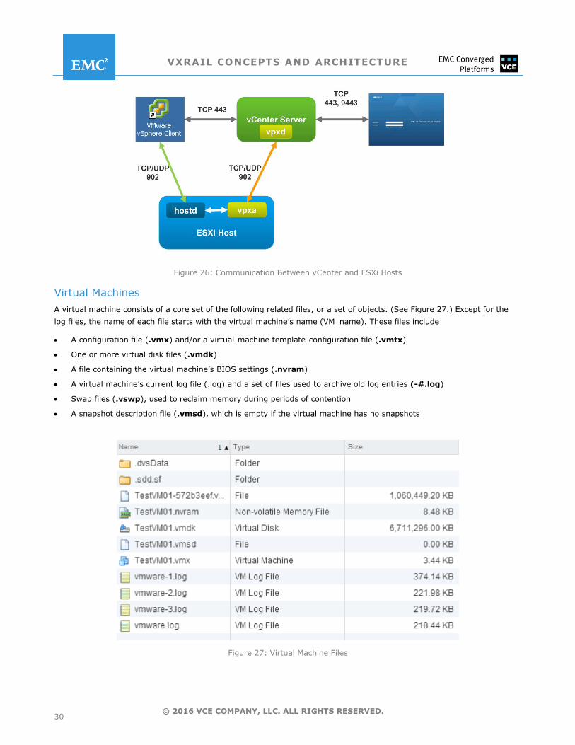
Communication Between vCenter Server and ESXi Hosts
vCenter Server communicates with the ESXi host through a vCenter Server agent, also referred to as vpxa or the
vmware-vpxa service, which is started on the ESXi host when it is added to the vCenter Server inventory. (See Figure
26.) Specifically, the vCenter vpxd daemon communicates through the vpxa to the ESXi host daemon known as the
hostd process. The vpxa process acts as an intermediary between the vpxd process that runs on vCenter Server and the
hostd process that runs on the ESXi host, relaying the tasks to perform on the host. The hostd process runs directly on
the ESXi host and is responsible for managing most of the operations on the ESXi host including creating VMs, migrating
VMs, and powering on VMs.
VXRAIL CONCEPTS AND ARCHITECTURE
30 © 2016 VCE COMPANY, LLC. ALL RIGHTS RESERVED.
Figure 26: Communication Between vCenter and ESXi Hosts
Virtual Machines
A virtual machine consists of a core set of the following related files, or a set of objects. (See Figure 27.) Except for the
log files, the name of each file starts with the virtual machine’s name (VM_name). These files include
A configuration file (.vmx) and/or a virtual-machine template-configuration file (.vmtx)
One or more virtual disk files (.vmdk)
A file containing the virtual machine’s BIOS settings (.nvram)
A virtual machine’s current log file (.log) and a set of files used to archive old log entries (-#.log)
Swap files (.vswp), used to reclaim memory during periods of contention
A snapshot description file (.vmsd), which is empty if the virtual machine has no snapshots
Figure 27: Virtual Machine Files
VXRAIL CONCEPTS AND ARCHITECTURE
31 © 2016 VCE COMPANY, LLC. ALL RIGHTS RESERVED.
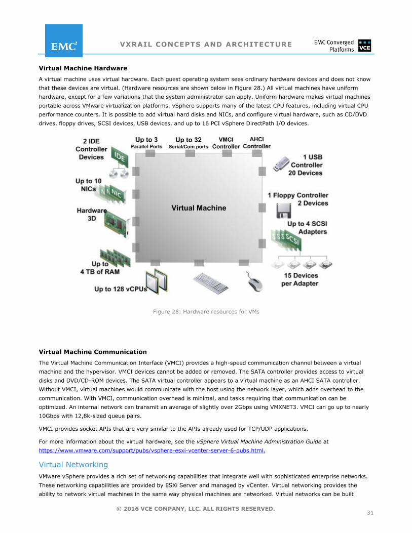
Virtual Machine Hardware
A virtual machine uses virtual hardware. Each guest operating system sees ordinary hardware devices and does not know
that these devices are virtual. (Hardware resources are shown below in Figure 28.) All virtual machines have uniform
hardware, except for a few variations that the system administrator can apply. Uniform hardware makes virtual machines
portable across VMware virtualization platforms. vSphere supports many of the latest CPU features, including virtual CPU
performance counters. It is possible to add virtual hard disks and NICs, and configure virtual hardware, such as CD/DVD
drives, floppy drives, SCSI devices, USB devices, and up to 16 PCI vSphere DirectPath I/O devices.
Figure 28: Hardware resources for VMs
Virtual Machine Communication
The Virtual Machine Communication Interface (VMCI) provides a high-speed communication channel between a virtual
machine and the hypervisor. VMCI devices cannot be added or removed. The SATA controller provides access to virtual
disks and DVD/CD-ROM devices. The SATA virtual controller appears to a virtual machine as an AHCI SATA controller.
Without VMCI, virtual machines would communicate with the host using the network layer, which adds overhead to the
communication. With VMCI, communication overhead is minimal, and tasks requiring that communication can be
optimized. An internal network can transmit an average of slightly over 2Gbps using VMXNET3. VMCI can go up to nearly
10Gbps with 12,8k-sized queue pairs.
VMCI provides socket APIs that are very similar to the APIs already used for TCP/UDP applications.
For more information about the virtual hardware, see the vSphere Virtual Machine Administration Guide at
https://www.vmware.com/support/pubs/vsphere-esxi-vcenter-server-6-pubs.html.
Virtual Networking
VMware vSphere provides a rich set of networking capabilities that integrate well with sophisticated enterprise networks.
These networking capabilities are provided by ESXi Server and managed by vCenter. Virtual networking provides the
ability to network virtual machines in the same way physical machines are networked. Virtual networks can be built
VXRAIL CONCEPTS AND ARCHITECTURE
32 © 2016 VCE COMPANY, LLC. ALL RIGHTS RESERVED.
withina single ESX Server host or across multiple ESX Server hosts. Virtual switches allow virtual machines on the same
ESX Server host to communicate with each other using the same protocols that would be used over physical switches,
without the need for additional networking hardware. ESX Server virtual switches also support VLANs that are compatible
with standard VLAN implementations from other vendors. A virtual switch, like a physical Ethernet switch, forwards frames
at the data link layer.A virtual machine can be configured with one or more virtual Ethernet adapters, each of which has
its own IP address and MAC address. As a result, virtual machines have the same properties as physical machines from a
networking standpoint. In addition, virtual networks enable functionality not possible with physical networks today. The
key virtual networking components provided by vSphereare virtual Ethernet adapters, used by individual virtual machines
and virtual switches, which connect virtual machines to each other and connect both virtual machines and the ESX Server
service console to external networks.
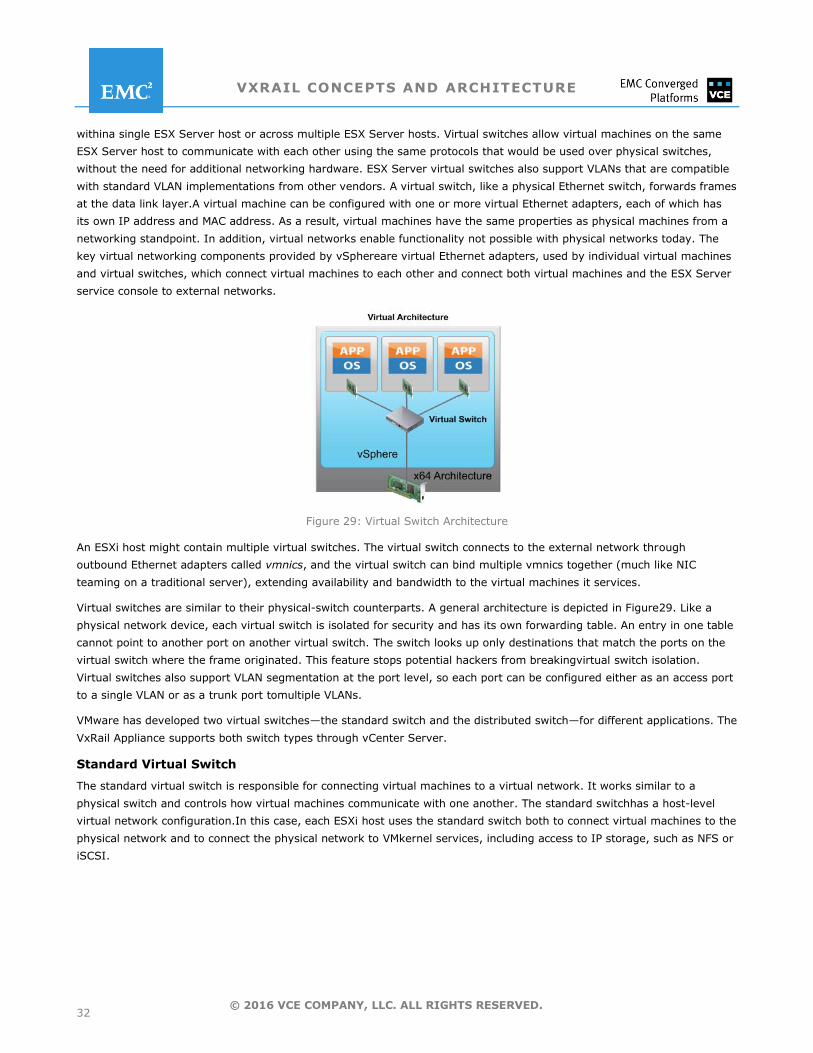
Figure 29: Virtual Switch Architecture
An ESXi host might contain multiple virtual switches. The virtual switch connects to the external network through
outbound Ethernet adapters called vmnics, and the virtual switch can bind multiple vmnics together (much like NIC
teaming on a traditional server), extending availability and bandwidth to the virtual machines it services.
Virtual switches are similar to their physical-switch counterparts. A general architecture is depicted in Figure29. Like a
physical network device, each virtual switch is isolated for security and has its own forwarding table. An entry in one table
cannot point to another port on another virtual switch. The switch looks up only destinations that match the ports on the
virtual switch where the frame originated. This feature stops potential hackers from breakingvirtual switch isolation.
Virtual switches also support VLAN segmentation at the port level, so each port can be configured either as an access port
to a single VLAN or as a trunk port tomultiple VLANs.
VMware has developed two virtual switches—the standard switch and the distributed switch—for different applications. The
VxRail Appliance supports both switch types through vCenter Server.
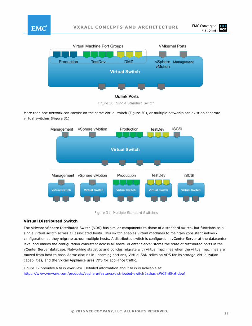
Standard Virtual Switch
The standard virtual switch is responsible for connecting virtual machines to a virtual network. It works similar to a
physical switch and controls how virtual machines communicate with one another. The standard switchhas a host-level
virtual network configuration.In this case, each ESXi host uses the standard switch both to connect virtual machines to the
physical network and to connect the physical network to VMkernel services, including access to IP storage, such as NFS or
iSCSI.
VXRAIL CONCEPTS AND ARCHITECTURE
33 © 2016 VCE COMPANY, LLC. ALL RIGHTS RESERVED.
Figure 30: Single Standard Switch
More than one network can coexist on the same virtual switch (Figure 30), or multiple networks can exist on separate
virtual switches (Figure 31).
Figure 31: Multiple Standard Switches
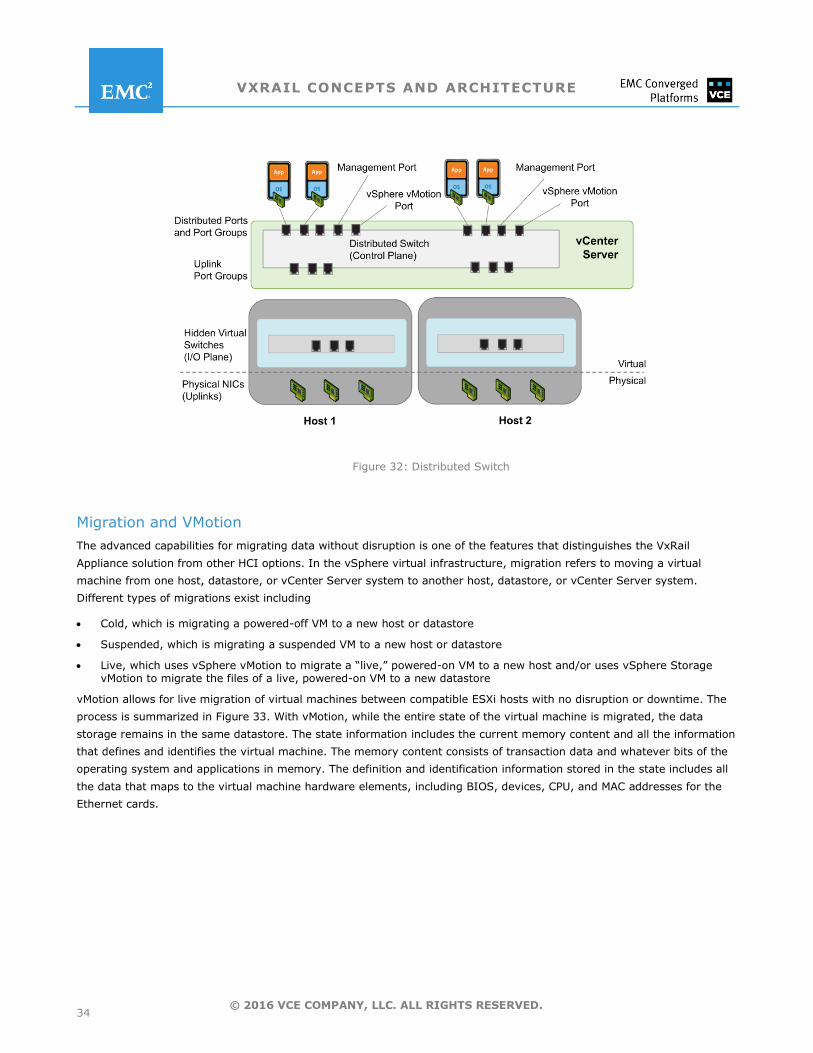
Virtual Distributed Switch
The VMware vSphere Distributed Switch (VDS) has similar components to those of a standard switch, but functions as a
single virtual switch across all associated hosts. This switch enables virtual machines to maintain consistent network
configuration as they migrate across multiple hosts. A distributed switch is configured in vCenter Server at the datacenter
level and makes the configuration consistent across all hosts. vCenter Server stores the state of distributed ports in the
vCenter Server database. Networking statistics and policies migrate with virtual machines when the virtual machines are
moved from host to host. As we discuss in upcoming sections, Virtual SAN relies on VDS for its storage-virtualization
capabilities, and the VxRail Appliance uses VDS for appliance traffic.
Figure 32 provides a VDS overview. Detailed information about VDS is available at:
https://www.vmware.com/products/vsphere/features/distributed-switch#sthash.WC5hSHzt.dpuf
VXRAIL CONCEPTS AND ARCHITECTURE
34 © 2016 VCE COMPANY, LLC. ALL RIGHTS RESERVED.
Figure 32: Distributed Switch
Migration and VMotion
The advanced capabilities for migrating data without disruption is one of the features that distinguishes the VxRail
Appliance solution from other HCI options. In the vSphere virtual infrastructure, migration refers to moving a virtual
machine from one host, datastore, or vCenter Server system to another host, datastore, or vCenter Server system.
Different types of migrations exist including
Cold, which is migrating a powered-off VM to a new host or datastore
Suspended, which is migrating a suspended VM to a new host or datastore
Live, which uses vSphere vMotion to migrate a ―live,‖ powered-on VM to a new host and/or uses vSphere Storage vMotion to migrate the files of a live, powered-on VM to a new datastore
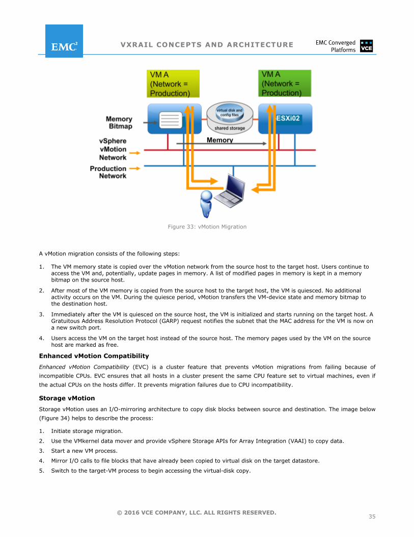
vMotion allows for live migration of virtual machines between compatible ESXi hosts with no disruption or downtime. The
process is summarized in Figure 33. With vMotion, while the entire state of the virtual machine is migrated, the data
storage remains in the same datastore. The state information includes the current memory content and all the information
that defines and identifies the virtual machine. The memory content consists of transaction data and whatever bits of the
operating system and applications in memory. The definition and identification information stored in the state includes all
the data that maps to the virtual machine hardware elements, including BIOS, devices, CPU, and MAC addresses for the
Ethernet cards.
VXRAIL CONCEPTS AND ARCHITECTURE
35 © 2016 VCE COMPANY, LLC. ALL RIGHTS RESERVED.
Figure 33: vMotion Migration
A vMotion migration consists of the following steps:
1. The VM memory state is copied over the vMotion network from the source host to the target host. Users continue to access the VM and, potentially, update pages in memory. A list of modified pages in memory is kept in a memory bitmap on the source host.
2. After most of the VM memory is copied from the source host to the target host, the VM is quiesced. No additional activity occurs on the VM. During the quiesce period, vMotion transfers the VM-device state and memory bitmap to the destination host.
3. Immediately after the VM is quiesced on the source host, the VM is initialized and starts running on the target host. A Gratuitous Address Resolution Protocol (GARP) request notifies the subnet that the MAC address for the VM is now on a new switch port.
4. Users access the VM on the target host instead of the source host. The memory pages used by the VM on the source host are marked as free.
Enhanced vMotion Compatibility
Enhanced vMotion Compatibility (EVC) is a cluster feature that prevents vMotion migrations from failing because of
incompatible CPUs. EVC ensures that all hosts in a cluster present the same CPU feature set to virtual machines, even if
the actual CPUs on the hosts differ. It prevents migration failures due to CPU incompatibility.
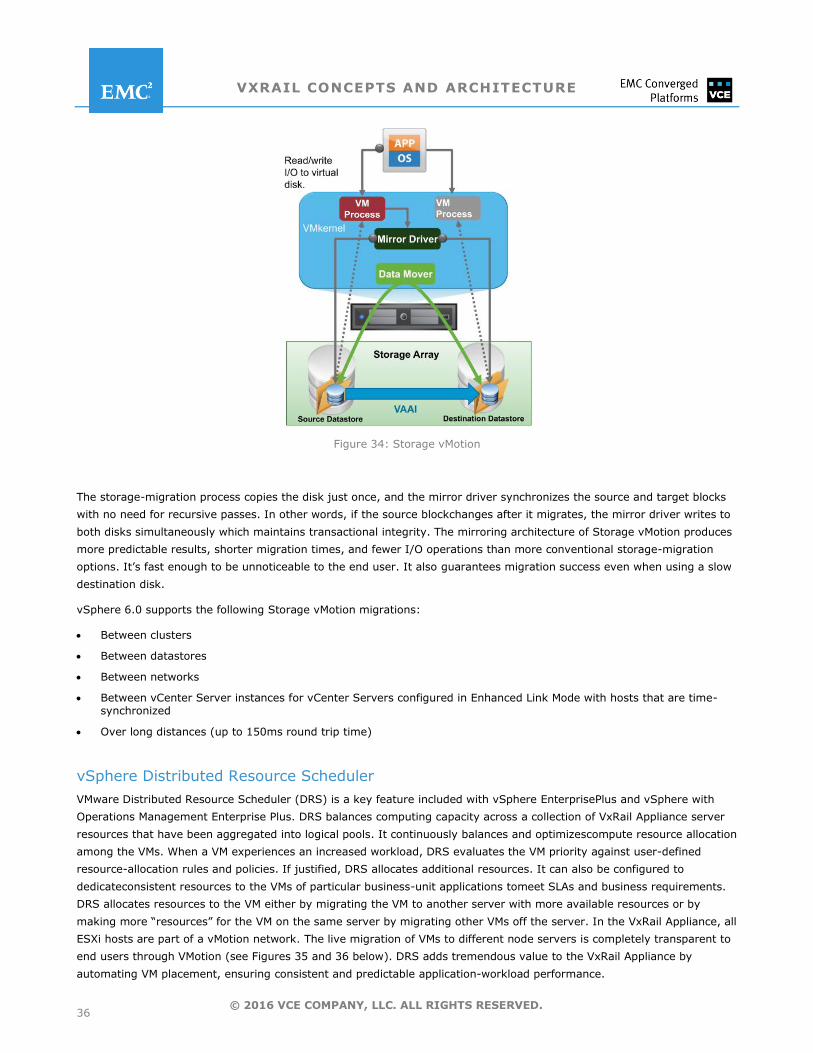
Storage vMotion
Storage vMotion uses an I/O-mirroring architecture to copy disk blocks between source and destination. The image below
(Figure 34) helps to describe the process:
1. Initiate storage migration.
2. Use the VMkernel data mover and provide vSphere Storage APIs for Array Integration (VAAI) to copy data.
3. Start a new VM process.
4. Mirror I/O calls to file blocks that have already been copied to virtual disk on the target datastore.
5. Switch to the target-VM process to begin accessing the virtual-disk copy.
VXRAIL CONCEPTS AND ARCHITECTURE
36 © 2016 VCE COMPANY, LLC. ALL RIGHTS RESERVED.
Figure 34: Storage vMotion
The storage-migration process copies the disk just once, and the mirror driver synchronizes the source and target blocks
with no need for recursive passes. In other words, if the source blockchanges after it migrates, the mirror driver writes to
both disks simultaneously which maintains transactional integrity. The mirroring architecture of Storage vMotion produces
more predictable results, shorter migration times, and fewer I/O operations than more conventional storage-migration
options. It’s fast enough to be unnoticeable to the end user. It also guarantees migration success even when using a slow
destination disk.
vSphere 6.0 supports the following Storage vMotion migrations:
Between clusters
Between datastores
Between networks
Between vCenter Server instances for vCenter Servers configured in Enhanced Link Mode with hosts that are time-synchronized
Over long distances (up to 150ms round trip time)
vSphere Distributed Resource Scheduler
VMware Distributed Resource Scheduler (DRS) is a key feature included with vSphere EnterprisePlus and vSphere with
Operations Management Enterprise Plus. DRS balances computing capacity across a collection of VxRail Appliance server
resources that have been aggregated into logical pools. It continuously balances and optimizescompute resource allocation
among the VMs. When a VM experiences an increased workload, DRS evaluates the VM priority against user-defined
resource-allocation rules and policies. If justified, DRS allocates additional resources. It can also be configured to
dedicateconsistent resources to the VMs of particular business-unit applications tomeet SLAs and business requirements.
DRS allocates resources to the VM either by migrating the VM to another server with more available resources or by
making more ―resources‖ for the VM on the same server by migrating other VMs off the server. In the VxRail Appliance, all
ESXi hosts are part of a vMotion network. The live migration of VMs to different node servers is completely transparent to
end users through VMotion (see Figures 35 and 36 below). DRS adds tremendous value to the VxRail Appliance by
automating VM placement, ensuring consistent and predictable application-workload performance.
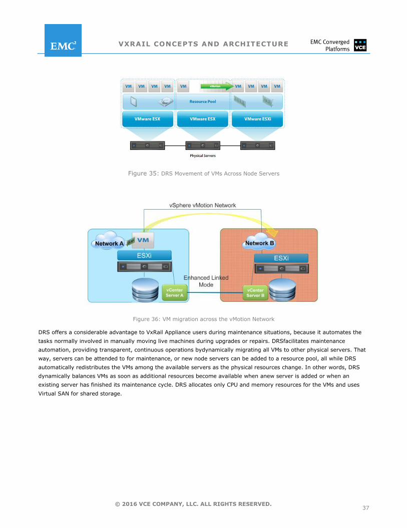
VXRAIL CONCEPTS AND ARCHITECTURE
37 © 2016 VCE COMPANY, LLC. ALL RIGHTS RESERVED.
Figure 35: DRS Movement of VMs Across Node Servers
Figure 36: VM migration across the vMotion Network
DRS offers a considerable advantage to VxRail Appliance users during maintenance situations, because it automates the
tasks normally involved in manually moving live machines during upgrades or repairs. DRSfacilitates maintenance
automation, providing transparent, continuous operations bydynamically migrating all VMs to other physical servers. That
way, servers can be attended to for maintenance, or new node servers can be added to a resource pool, all while DRS
automatically redistributes the VMs among the available servers as the physical resources change. In other words, DRS
dynamically balances VMs as soon as additional resources become available when anew server is added or when an
existing server has finished its maintenance cycle. DRS allocates only CPU and memory resources for the VMs and uses
Virtual SAN for shared storage.
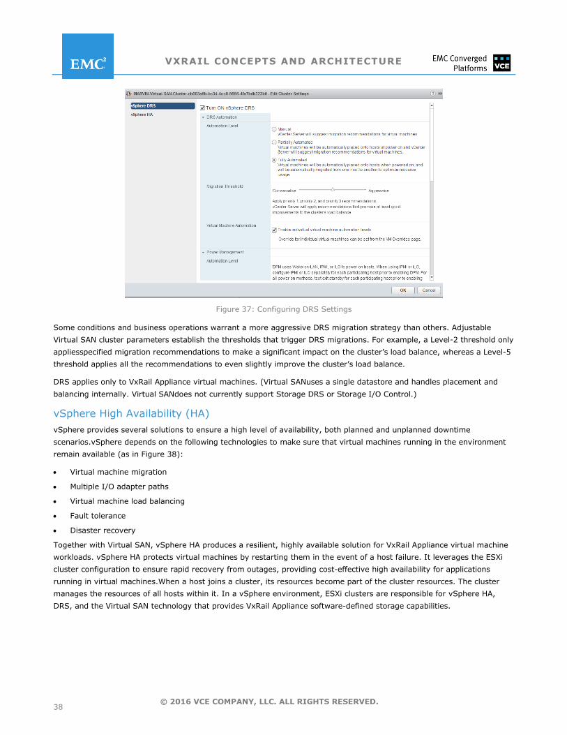
VXRAIL CONCEPTS AND ARCHITECTURE
38 © 2016 VCE COMPANY, LLC. ALL RIGHTS RESERVED.
Figure 37: Configuring DRS Settings
Some conditions and business operations warrant a more aggressive DRS migration strategy than others. Adjustable
Virtual SAN cluster parameters establish the thresholds that trigger DRS migrations. For example, a Level-2 threshold only
appliesspecified migration recommendations to make a significant impact on the cluster’s load balance, whereas a Level-5
threshold applies all the recommendations to even slightly improve the cluster’s load balance.
DRS applies only to VxRail Appliance virtual machines. (Virtual SANuses a single datastore and handles placement and
balancing internally. Virtual SANdoes not currently support Storage DRS or Storage I/O Control.)
vSphere High Availability (HA)
vSphere provides several solutions to ensure a high level of availability, both planned and unplanned downtime
scenarios.vSphere depends on the following technologies to make sure that virtual machines running in the environment
remain available (as in Figure 38):
Virtual machine migration
Multiple I/O adapter paths
Virtual machine load balancing
Fault tolerance
Disaster recovery
Together with Virtual SAN, vSphere HA produces a resilient, highly available solution for VxRail Appliance virtual machine
workloads. vSphere HA protects virtual machines by restarting them in the event of a host failure. It leverages the ESXi
cluster configuration to ensure rapid recovery from outages, providing cost-effective high availability for applications
running in virtual machines.When a host joins a cluster, its resources become part of the cluster resources. The cluster
manages the resources of all hosts within it. In a vSphere environment, ESXi clusters are responsible for vSphere HA,
DRS, and the Virtual SAN technology that provides VxRail Appliance software-defined storage capabilities.
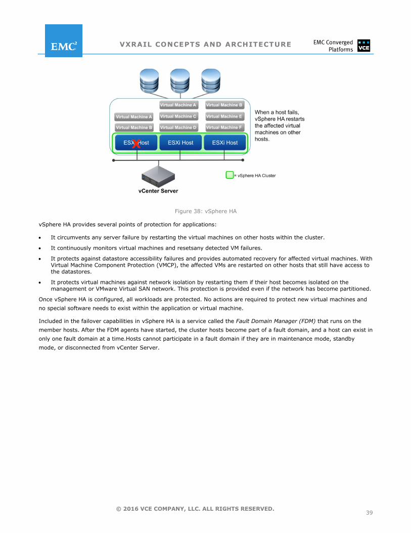
VXRAIL CONCEPTS AND ARCHITECTURE
39 © 2016 VCE COMPANY, LLC. ALL RIGHTS RESERVED.
Figure 38: vSphere HA
vSphere HA provides several points of protection for applications:
It circumvents any server failure by restarting the virtual machines on other hosts within the cluster.
It continuously monitors virtual machines and resetsany detected VM failures.
It protects against datastore accessibility failures and provides automated recovery for affected virtual machines. With Virtual Machine Component Protection (VMCP), the affected VMs are restarted on other hosts that still have access to the datastores.
It protects virtual machines against network isolation by restarting them if their host becomes isolated on the management or VMware Virtual SAN network. This protection is provided even if the network has become partitioned.
Once vSphere HA is configured, all workloads are protected. No actions are required to protect new virtual machines and
no special software needs to exist within the application or virtual machine.
Included in the failover capabilities in vSphere HA is a service called the Fault Domain Manager (FDM) that runs on the
member hosts. After the FDM agents have started, the cluster hosts become part of a fault domain, and a host can exist in
only one fault domain at a time.Hosts cannot participate in a fault domain if they are in maintenance mode, standby
mode, or disconnected from vCenter Server.
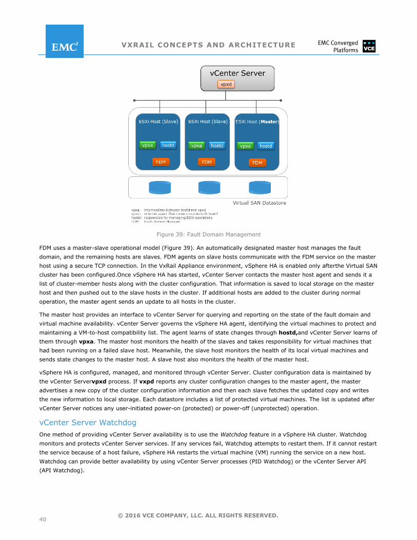
VXRAIL CONCEPTS AND ARCHITECTURE
40 © 2016 VCE COMPANY, LLC. ALL RIGHTS RESERVED.
Figure 39: Fault Domain Management
FDM uses a master-slave operational model (Figure 39). An automatically designated master host manages the fault
domain, and the remaining hosts are slaves. FDM agents on slave hosts communicate with the FDM service on the master
host using a secure TCP connection. In the VxRail Appliance environment, vSphere HA is enabled only afterthe Virtual SAN
cluster has been configured.Once vSphere HA has started, vCenter Server contacts the master host agent and sends it a
list of cluster-member hosts along with the cluster configuration. That information is saved to local storage on the master
host and then pushed out to the slave hosts in the cluster. If additional hosts are added to the cluster during normal
operation, the master agent sends an update to all hosts in the cluster.
The master host provides an interface to vCenter Server for querying and reporting on the state of the fault domain and
virtual machine availability. vCenter Server governs the vSphere HA agent, identifying the virtual machines to protect and
maintaining a VM-to-host compatibility list. The agent learns of state changes through hostd,and vCenter Server learns of
them through vpxa. The master host monitors the health of the slaves and takes responsibility for virtual machines that
had been running on a failed slave host. Meanwhile, the slave host monitors the health of its local virtual machines and
sends state changes to the master host. A slave host also monitors the health of the master host.
vSphere HA is configured, managed, and monitored through vCenter Server. Cluster configuration data is maintained by
the vCenter Servervpxd process. If vxpd reports any cluster configuration changes to the master agent, the master
advertises a new copy of the cluster configuration information and then each slave fetches the updated copy and writes
the new information to local storage. Each datastore includes a list of protected virtual machines. The list is updated after
vCenter Server notices any user-initiated power-on (protected) or power-off (unprotected) operation.
vCenter Server Watchdog
One method of providing vCenter Server availability is to use the Watchdog feature in a vSphere HA cluster. Watchdog
monitors and protects vCenter Server services. If any services fail, Watchdog attempts to restart them. If it cannot restart
the service because of a host failure, vSphere HA restarts the virtual machine (VM) running the service on a new host.
Watchdog can provide better availability by using vCenter Server processes (PID Watchdog) or the vCenter Server API
(API Watchdog).
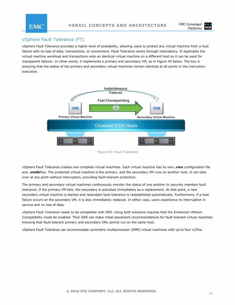
VXRAIL CONCEPTS AND ARCHITECTURE
41 © 2016 VCE COMPANY, LLC. ALL RIGHTS RESERVED.
vSphere Fault Tolerance (FT)
vSphere Fault Tolerance provides a higher level of availability, allowing users to protect any virtual machine from a host
failure with no loss of data, transactions, or connections. Fault Tolerance works through redundancy. It duplicates the
virtual machine workload and transactions onto an identical virtual machine on a different host so it can be used for
transparent failover. In other words, it implements a primary and secondary VM, as in Figure 40 below. The key is
ensuring that the states of the primary and secondary virtual machines remain identical at all points in the instruction
execution.
Figure 40: Fault Tolerance
vSphere Fault Tolerance creates two complete virtual machines. Each virtual machine has its own .vmx configuration file
and .vmdkfiles. The protected virtual machine is the primary, and the secondary VM runs on another host. It can take
over at any point without interruption, providing fault-tolerant protection.
The primary and secondary virtual machines continuously monitor the status of one another to securely maintain fault
tolerance. If the primary VM fails, the secondary is activated immediately as a replacement. At that point, a new
secondary virtual machine is started and redundant fault tolerance is reestablished automatically. Furthermore, if a host
failure occurs on the secondary VM, it is also immediately replaced. In either case, users experience no interruption in
service and no loss of data.
vSphere Fault Tolerance needs to be compatible with DRS. Using both solutions requires that the Enhanced vMotion
Compatibility mode be enabled. Then DRS can make initial placement recommendations for fault-tolerant virtual machines
knowing that fault-tolerant primary and secondary VMs cannot run on the same host.
vSphere Fault Tolerance can accommodate symmetric multiprocessor (SMP) virtual machines with up to four vCPUs.
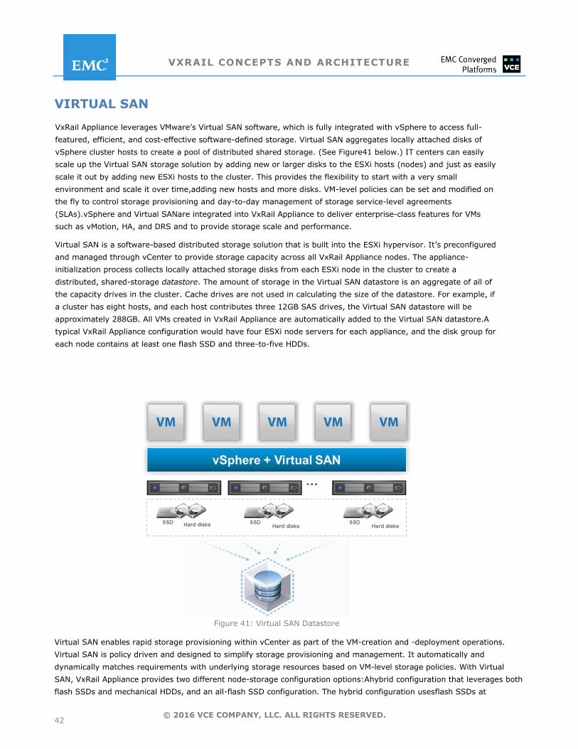
VXRAIL CONCEPTS AND ARCHITECTURE
42 © 2016 VCE COMPANY, LLC. ALL RIGHTS RESERVED.
VIRTUAL SAN
VxRail Appliance leverages VMware’s Virtual SAN software, which is fully integrated with vSphere to access full-
featured, efficient, and cost-effective software-defined storage. Virtual SAN aggregates locally attached disks of
vSphere cluster hosts to create a pool of distributed shared storage. (See Figure41 below.) IT centers can easily
scale up the Virtual SAN storage solution by adding new or larger disks to the ESXi hosts (nodes) and just as easily
scale it out by adding new ESXi hosts to the cluster. This provides the flexibility to start with a very small
environment and scale it over time,adding new hosts and more disks. VM-level policies can be set and modified on
the fly to control storage provisioning and day-to-day management of storage service-level agreements
(SLAs).vSphere and Virtual SANare integrated into VxRail Appliance to deliver enterprise-class features for VMs
such as vMotion, HA, and DRS and to provide storage scale and performance.
Virtual SAN is a software-based distributed storage solution that is built into the ESXi hypervisor. It’s preconfigured
and managed through vCenter to provide storage capacity across all VxRail Appliance nodes. The appliance-
initialization process collects locally attached storage disks from each ESXi node in the cluster to create a
distributed, shared-storage datastore. The amount of storage in the Virtual SAN datastore is an aggregate of all of
the capacity drives in the cluster. Cache drives are not used in calculating the size of the datastore. For example, if
a cluster has eight hosts, and each host contributes three 12GB SAS drives, the Virtual SAN datastore will be
approximately 288GB. All VMs created in VxRail Appliance are automatically added to the Virtual SAN datastore.A
typical VxRail Appliance configuration would have four ESXi node servers for each appliance, and the disk group for
each node contains at least one flash SSD and three-to-five HDDs.
Figure 41: Virtual SAN Datastore
Virtual SAN enables rapid storage provisioning within vCenter as part of the VM-creation and -deployment operations.
Virtual SAN is policy driven and designed to simplify storage provisioning and management. It automatically and
dynamically matches requirements with underlying storage resources based on VM-level storage policies. With Virtual
SAN, VxRail Appliance provides two different node-storage configuration options:Ahybrid configuration that leverages both
flash SSDs and mechanical HDDs, and an all-flash SSD configuration. The hybrid configuration usesflash SSDs at
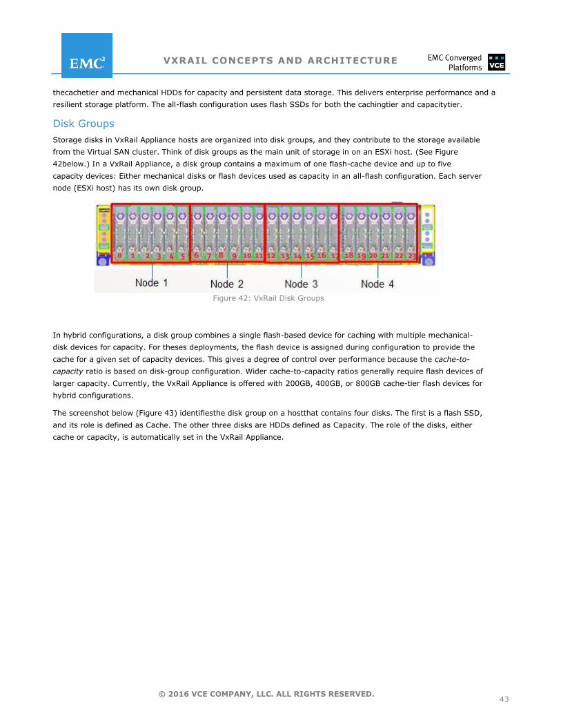
VXRAIL CONCEPTS AND ARCHITECTURE
43 © 2016 VCE COMPANY, LLC. ALL RIGHTS RESERVED.
thecachetier and mechanical HDDs for capacity and persistent data storage. This delivers enterprise performance and a
resilient storage platform. The all-flash configuration uses flash SSDs for both the cachingtier and capacitytier.
Disk Groups
Storage disks in VxRail Appliance hosts are organized into disk groups, and they contribute to the storage available
from the Virtual SAN cluster. Think of disk groups as the main unit of storage in on an ESXi host. (See Figure
42below.) In a VxRail Appliance, a disk group contains a maximum of one flash-cache device and up to five
capacity devices: Either mechanical disks or flash devices used as capacity in an all-flash configuration. Each server
node (ESXi host) has its own disk group.
Figure 42: VxRail Disk Groups
In hybrid configurations, a disk group combines a single flash-based device for caching with multiple mechanical-
disk devices for capacity. For theses deployments, the flash device is assigned during configuration to provide the
cache for a given set of capacity devices. This gives a degree of control over performance because the cache-to-
capacity ratio is based on disk-group configuration. Wider cache-to-capacity ratios generally require flash devices of
larger capacity. Currently, the VxRail Appliance is offered with 200GB, 400GB, or 800GB cache-tier flash devices for
hybrid configurations.
The screenshot below (Figure 43) identifiesthe disk group on a hostthat contains four disks. The first is a flash SSD,
and its role is defined as Cache. The other three disks are HDDs defined as Capacity. The role of the disks, either
cache or capacity, is automatically set in the VxRail Appliance.
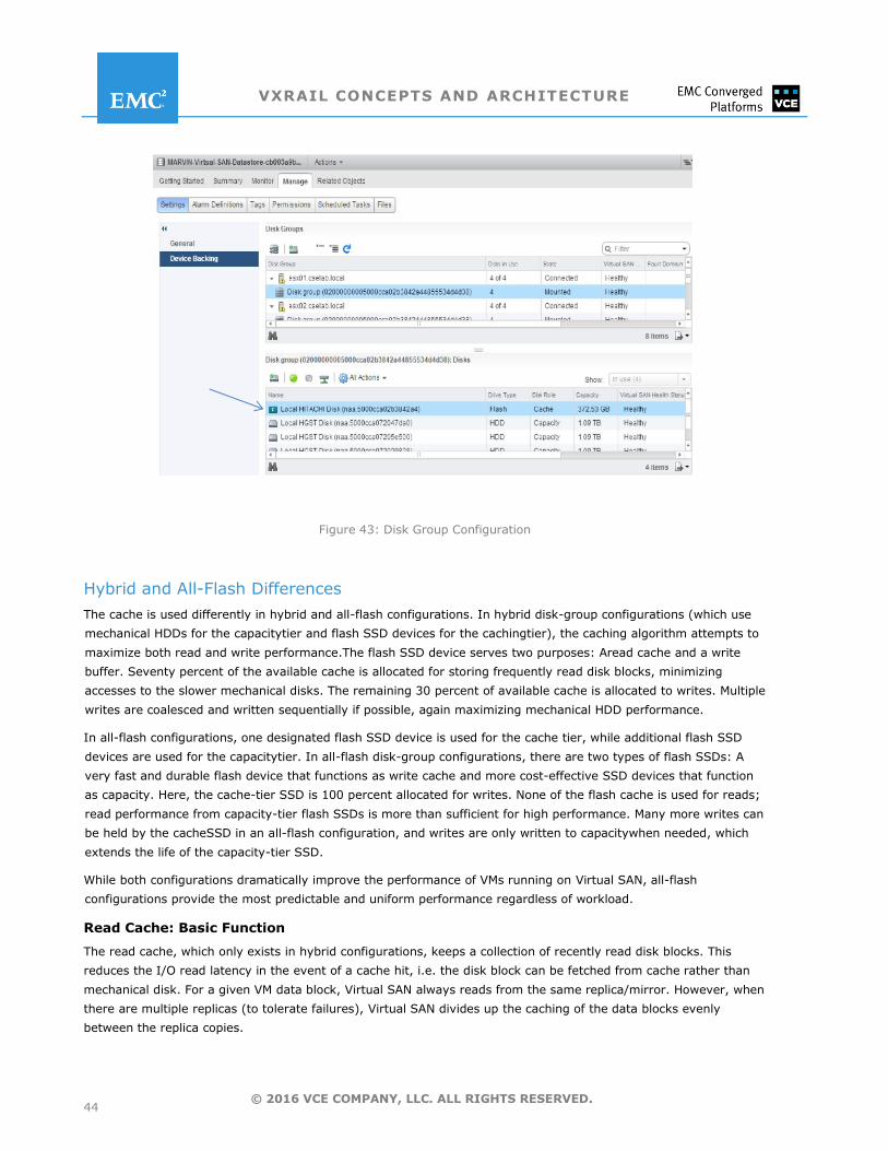
VXRAIL CONCEPTS AND ARCHITECTURE
44 © 2016 VCE COMPANY, LLC. ALL RIGHTS RESERVED.
Figure 43: Disk Group Configuration
Hybrid and All-Flash Differences
The cache is used differently in hybrid and all-flash configurations. In hybrid disk-group configurations (which use
mechanical HDDs for the capacitytier and flash SSD devices for the cachingtier), the caching algorithm attempts to
maximize both read and write performance.The flash SSD device serves two purposes: Aread cache and a write
buffer. Seventy percent of the available cache is allocated for storing frequently read disk blocks, minimizing
accesses to the slower mechanical disks. The remaining 30 percent of available cache is allocated to writes. Multiple
writes are coalesced and written sequentially if possible, again maximizing mechanical HDD performance.
In all-flash configurations, one designated flash SSD device is used for the cache tier, while additional flash SSD
devices are used for the capacitytier. In all-flash disk-group configurations, there are two types of flash SSDs: A
very fast and durable flash device that functions as write cache and more cost-effective SSD devices that function
as capacity. Here, the cache-tier SSD is 100 percent allocated for writes. None of the flash cache is used for reads;
read performance from capacity-tier flash SSDs is more than sufficient for high performance. Many more writes can
be held by the cacheSSD in an all-flash configuration, and writes are only written to capacitywhen needed, which
extends the life of the capacity-tier SSD.
While both configurations dramatically improve the performance of VMs running on Virtual SAN, all-flash
configurations provide the most predictable and uniform performance regardless of workload.
Read Cache: Basic Function
The read cache, which only exists in hybrid configurations, keeps a collection of recently read disk blocks. This
reduces the I/O read latency in the event of a cache hit, i.e. the disk block can be fetched from cache rather than
mechanical disk. For a given VM data block, Virtual SAN always reads from the same replica/mirror. However, when
there are multiple replicas (to tolerate failures), Virtual SAN divides up the caching of the data blocks evenly
between the replica copies.
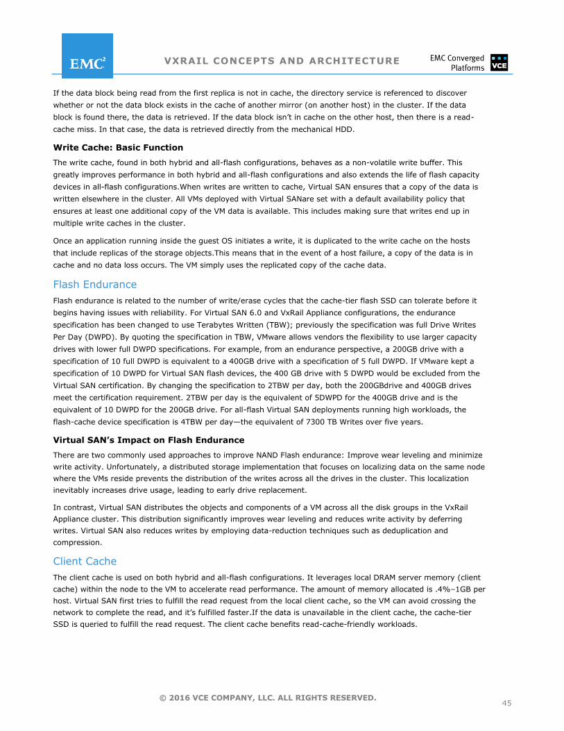
VXRAIL CONCEPTS AND ARCHITECTURE
45 © 2016 VCE COMPANY, LLC. ALL RIGHTS RESERVED.
If the data block being read from the first replica is not in cache, the directory service is referenced to discover
whether or not the data block exists in the cache of another mirror (on another host) in the cluster. If the data
block is found there, the data is retrieved. If the data block isn’t in cache on the other host, then there is a read-
cache miss. In that case, the data is retrieved directly from the mechanical HDD.
Write Cache: Basic Function
The write cache, found in both hybrid and all-flash configurations, behaves as a non-volatile write buffer. This
greatly improves performance in both hybrid and all-flash configurations and also extends the life of flash capacity
devices in all-flash configurations.When writes are written to cache, Virtual SAN ensures that a copy of the data is
written elsewhere in the cluster. All VMs deployed with Virtual SANare set with a default availability policy that
ensures at least one additional copy of the VM data is available. This includes making sure that writes end up in
multiple write caches in the cluster.
Once an application running inside the guest OS initiates a write, it is duplicated to the write cache on the hosts
that include replicas of the storage objects.This means that in the event of a host failure, a copy of the data is in
cache and no data loss occurs. The VM simply uses the replicated copy of the cache data.
Flash Endurance
Flash endurance is related to the number of write/erase cycles that the cache-tier flash SSD can tolerate before it
begins having issues with reliability. For Virtual SAN 6.0 and VxRail Appliance configurations, the endurance
specification has been changed to use Terabytes Written (TBW); previously the specification was full Drive Writes
Per Day (DWPD). By quoting the specification in TBW, VMware allows vendors the flexibility to use larger capacity
drives with lower full DWPD specifications. For example, from an endurance perspective, a 200GB drive with a
specification of 10 full DWPD is equivalent to a 400GB drive with a specification of 5 full DWPD. If VMware kept a
specification of 10 DWPD for Virtual SAN flash devices, the 400 GB drive with 5 DWPD would be excluded from the
Virtual SAN certification. By changing the specification to 2TBW per day, both the 200GBdrive and 400GB drives
meet the certification requirement. 2TBW per day is the equivalent of 5DWPD for the 400GB drive and is the
equivalent of 10 DWPD for the 200GB drive. For all-flash Virtual SAN deployments running high workloads, the
flash-cache device specification is 4TBW per day—the equivalent of 7300 TB Writes over five years.
Virtual SAN’s Impact on Flash Endurance
There are two commonly used approaches to improve NAND Flash endurance: Improve wear leveling and minimize
write activity. Unfortunately, a distributed storage implementation that focuses on localizing data on the same node
where the VMs reside prevents the distribution of the writes across all the drives in the cluster. This localization
inevitably increases drive usage, leading to early drive replacement.
In contrast, Virtual SAN distributes the objects and components of a VM across all the disk groups in the VxRail
Appliance cluster. This distribution significantly improves wear leveling and reduces write activity by deferring
writes. Virtual SAN also reduces writes by employing data-reduction techniques such as deduplication and
compression.
Client Cache
The client cache is used on both hybrid and all-flash configurations. It leverages local DRAM server memory (client
cache) within the node to the VM to accelerate read performance. The amount of memory allocated is .4%–1GB per
host. Virtual SAN first tries to fulfill the read request from the local client cache, so the VM can avoid crossing the
network to complete the read, and it’s fulfilled faster.If the data is unavailable in the client cache, the cache-tier
SSD is queried to fulfill the read request. The client cache benefits read-cache-friendly workloads.
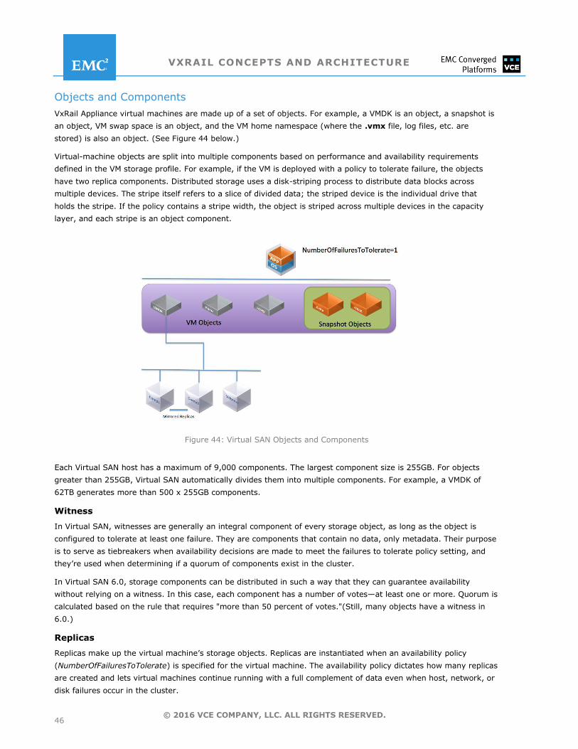
VXRAIL CONCEPTS AND ARCHITECTURE
46 © 2016 VCE COMPANY, LLC. ALL RIGHTS RESERVED.
Objects and Components
VxRail Appliance virtual machines are made up of a set of objects. For example, a VMDK is an object, a snapshot is
an object, VM swap space is an object, and the VM home namespace (where the .vmx file, log files, etc. are
stored) is also an object. (See Figure 44 below.)
Virtual-machine objects are split into multiple components based on performance and availability requirements
defined in the VM storage profile. For example, if the VM is deployed with a policy to tolerate failure, the objects
have two replica components. Distributed storage uses a disk-striping process to distribute data blocks across
multiple devices. The stripe itself refers to a slice of divided data; the striped device is the individual drive that
holds the stripe. If the policy contains a stripe width, the object is striped across multiple devices in the capacity
layer, and each stripe is an object component.
Figure 44: Virtual SAN Objects and Components
Each Virtual SAN host has a maximum of 9,000 components. The largest component size is 255GB. For objects
greater than 255GB, Virtual SAN automatically divides them into multiple components. For example, a VMDK of
62TB generates more than 500 x 255GB components.
Witness
In Virtual SAN, witnesses are generally an integral component of every storage object, as long as the object is
configured to tolerate at least one failure. They are components that contain no data, only metadata. Their purpose
is to serve as tiebreakers when availability decisions are made to meet the failures to tolerate policy setting, and
they’re used when determining if a quorum of components exist in the cluster.
In Virtual SAN 6.0, storage components can be distributed in such a way that they can guarantee availability
without relying on a witness. In this case, each component has a number of votes—at least one or more. Quorum is
calculated based on the rule that requires "more than 50 percent of votes."(Still, many objects have a witness in
6.0.)
Replicas
Replicas make up the virtual machine’s storage objects. Replicas are instantiated when an availability policy
(NumberOfFailuresToTolerate) is specified for the virtual machine. The availability policy dictates how many replicas
are created and lets virtual machines continue running with a full complement of data even when host, network, or
disk failures occur in the cluster.
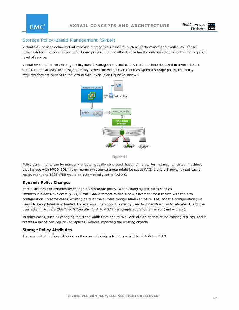
VXRAIL CONCEPTS AND ARCHITECTURE
47 © 2016 VCE COMPANY, LLC. ALL RIGHTS RESERVED.
Storage Policy-Based Management (SPBM)
Virtual SAN policies define virtual-machine storage requirements, such as performance and availability. These
policies determine how storage objects are provisioned and allocated within the datastore to guarantee the required
level of service.
Virtual SAN implements Storage Policy-Based Management, and each virtual machine deployed in a Virtual SAN
datastore has at least one assigned policy. When the VM is created and assigned a storage policy, the policy
requirements are pushed to the Virtual SAN layer. (See Figure 45 below.)
Figure 45
Policy assignments can be manually or automatically generated, based on rules. For instance, all virtual machines
that include with PROD-SQL in their name or resource group might be set at RAID-1 and a 5-percent read-cache
reservation, and TEST-WEB would be automatically set to RAID-0.
Dynamic Policy Changes
Administrators can dynamically change a VM storage policy. When changing attributes such as
NumberOfFailuresToTolerate (FTT), Virtual SAN attempts to find a new placement for a replica with the new
configuration. In some cases, existing parts of the current configuration can be reused, and the configuration just
needs to be updated or extended. For example, if an object currently uses NumberOfFailuresToTolerate=1, and the
user asks for NumberOfFailuresToTolerate=2, Virtual SAN can simply add another mirror (and witness).
In other cases, such as changing the stripe width from one to two, Virtual SAN cannot reuse existing replicas, and it
creates a brand new replica (or replicas) without impacting the existing objects.
Storage Policy Attributes
The screenshot in Figure 46displays the current policy attributes available with Virtual SAN:
VXRAIL CONCEPTS AND ARCHITECTURE
48 © 2016 VCE COMPANY, LLC. ALL RIGHTS RESERVED.
Figure 46: Virtual SAN Policy Attributes
Number of Disk Stripes per Object
This policy attribute establishes the minimum number of capacity devices used for striping each virtual-machine
replica. A value higher than 1 might result in better performance, but it also results in higher resource
consumption. The default value is the minimum 1, and the maximum value is 12. The stripe size is 1MB.
Virtual SAN may decide that an object needs to be striped across multiple disks without any stripe-width policy
requirement. The reason for this can vary, but typically it occurswhen a VMDK is too large to fit on a single physical
drive. However, when a particular stripe width is required, then it should not exceed the number of disks available
to the cluster.
Flash Cache Reservation
Flash Cache Reservation refers to flash capacity reserved as read cache for the virtual-machine object, and it
applies to hybrid configurations only. By default, Virtual SAN dynamically allocates read cache to storage objects
based on demand. As a result, no need typically exists to change the default 0 value for this parameter.
However, in very specific cases, when a small increase in the read cache for a single VM can provide a significant
change in performance, it is an option. It should be used with caution to avoid wasting resources or taking
resources from other VMs.
The default value is 0 percent. Maximum value is 100 percent.
Number of Failures to Tolerate
This FTT option generally defines the number of host and device failures that a virtual machine object can tolerate.
For n failures tolerated, n+1copies of the VM object area created and 2n+1 hosts with storage are required.
The default value is 1. Maximum value is 3.
Virtual SAN supports two specific configurations when erasure codes are enabled. The first, RAID-5, applies when
the number of failures to tolerate is set to 1, and the second, RAID-6, applies when the number of failures to
tolerate is set to 2. Note that a Virtual SAN cluster size needs to be at least four hosts for RAID-5 and at least six
hosts for RAID-6. Of course, it may be (much) larger than that.
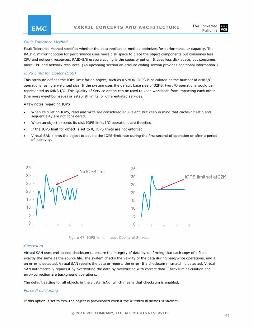
VXRAIL CONCEPTS AND ARCHITECTURE
49 © 2016 VCE COMPANY, LLC. ALL RIGHTS RESERVED.
Fault Tolerance Method
Fault Tolerance Method specifies whether the data-replication method optimizes for performance or capacity. The
RAID-1 mirroringoption for performance uses more disk space to place the object components but consumes less
CPU and network resources. RAID-5/6 erasure coding is the capacity option. It uses less disk space, but consumes
more CPU and network resources. (An upcoming section on erasure coding section provides additional information.)
IOPS Limit for Object (QoS)
This attribute defines the IOPS limit for an object, such as a VMDK. IOPS is calculated as the number of disk I/O
operations, using a weighted size. If the system uses the default base size of 32KB, two I/O operations would be
represented as 64KB I/O. This Quality of Service option can be used to keep workloads from impacting each other
(the noisy-neighbor issue) or establish limits for differentiated services.
A few notes regarding IOPS
When calculating IOPS, read and write are considered equivalent, but keep in mind that cache-hit ratio and sequentiality are not considered.
When an object exceeds its disk IOPS limit, I/O operations are throttled.
If the IOPS limit for object is set to 0, IOPS limits are not enforced.
Virtual SAN allows the object to double the IOPS-limit rate during the first second of operation or after a period of inactivity.
Figure 47: IOPS limits impact Quality of Service.
Checksum
Virtual SAN uses end-to-end checksum to ensure the integrity of data by confirming that each copy of a file is
exactly the same as the source file. The system checks the validity of the data during read/write operations, and if
an error is detected, Virtual SAN repairs the data or reports the error. If a checksum mismatch is detected, Virtual
SAN automatically repairs it by overwriting the data by overwriting with correct data. Checksum calculation and
error-correction are background operations.
The default setting for all objects in the cluster isNo, which means that checksum is enabled.
Force Provisioning
If this option is set to Yes, the object is provisioned even if the NumberOfFailuresToTolerate,
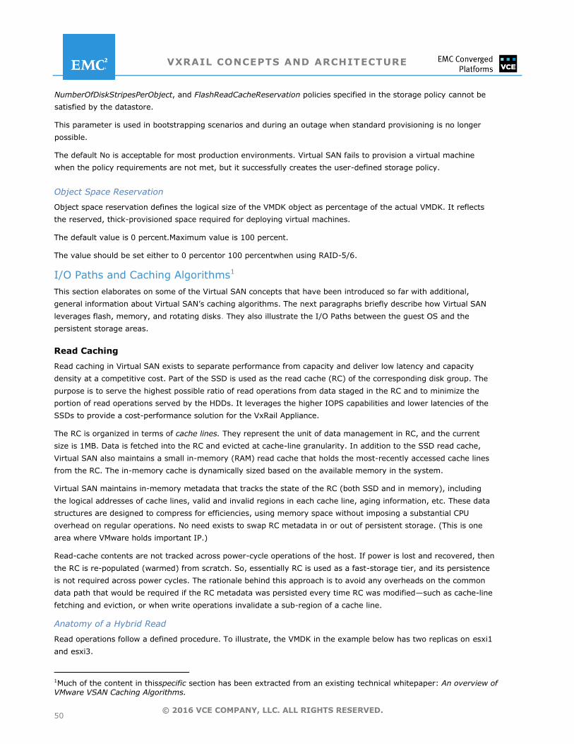
VXRAIL CONCEPTS AND ARCHITECTURE
50 © 2016 VCE COMPANY, LLC. ALL RIGHTS RESERVED.
NumberOfDiskStripesPerObject, and FlashReadCacheReservation policies specified in the storage policy cannot be
satisfied by the datastore.
This parameter is used in bootstrapping scenarios and during an outage when standard provisioning is no longer
possible.
The default No is acceptable for most production environments. Virtual SAN fails to provision a virtual machine
when the policy requirements are not met, but it successfully creates the user-defined storage policy.
Object Space Reservation
Object space reservation defines the logical size of the VMDK object as percentage of the actual VMDK. It reflects
the reserved, thick-provisioned space required for deploying virtual machines.
The default value is 0 percent.Maximum value is 100 percent.
The value should be set either to 0 percentor 100 percentwhen using RAID-5/6.
I/O Paths and Caching Algorithms1
This section elaborates on some of the Virtual SAN concepts that have been introduced so far with additional,
general information about Virtual SAN’s caching algorithms. The next paragraphs briefly describe how Virtual SAN
leverages flash, memory, and rotating disks. They also illustrate the I/O Paths between the guest OS and the
persistent storage areas.
Read Caching
Read caching in Virtual SAN exists to separate performance from capacity and deliver low latency and capacity
density at a competitive cost. Part of the SSD is used as the read cache (RC) of the corresponding disk group. The
purpose is to serve the highest possible ratio of read operations from data staged in the RC and to minimize the
portion of read operations served by the HDDs. It leverages the higher IOPS capabilities and lower latencies of the
SSDs to provide a cost-performance solution for the VxRail Appliance.
The RC is organized in terms of cache lines. They represent the unit of data management in RC, and the current
size is 1MB. Data is fetched into the RC and evicted at cache-line granularity. In addition to the SSD read cache,
Virtual SAN also maintains a small in-memory (RAM) read cache that holds the most-recently accessed cache lines
from the RC. The in-memory cache is dynamically sized based on the available memory in the system.
Virtual SAN maintains in-memory metadata that tracks the state of the RC (both SSD and in memory), including
the logical addresses of cache lines, valid and invalid regions in each cache line, aging information, etc. These data
structures are designed to compress for efficiencies, using memory space without imposing a substantial CPU
overhead on regular operations. No need exists to swap RC metadata in or out of persistent storage. (This is one
area where VMware holds important IP.)
Read-cache contents are not tracked across power-cycle operations of the host. If power is lost and recovered, then
the RC is re-populated (warmed) from scratch. So, essentially RC is used as a fast-storage tier, and its persistence
is not required across power cycles. The rationale behind this approach is to avoid any overheads on the common
data path that would be required if the RC metadata was persisted every time RC was modified—such as cache-line
fetching and eviction, or when write operations invalidate a sub-region of a cache line.
Anatomy of a Hybrid Read
Read operations follow a defined procedure. To illustrate, the VMDK in the example below has two replicas on esxi1
and esxi3.
1Much of the content in thisspecific section has been extracted from an existing technical whitepaper: An overview of VMware VSAN Caching Algorithms.
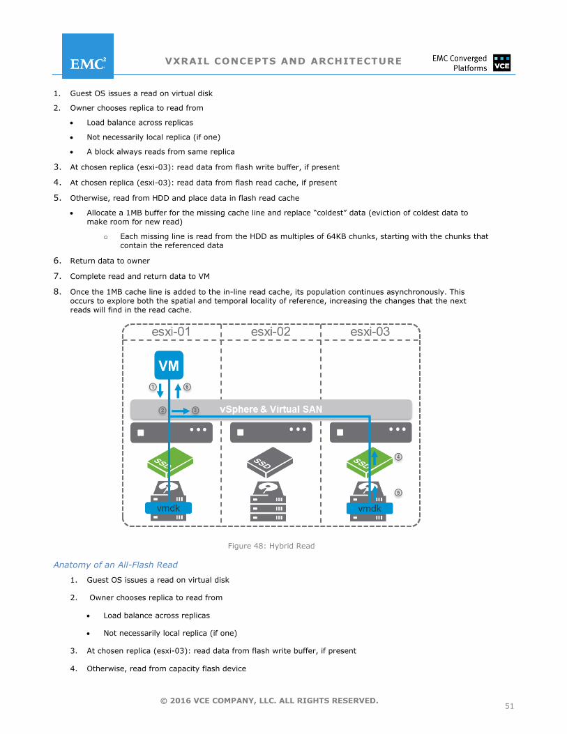
VXRAIL CONCEPTS AND ARCHITECTURE
51 © 2016 VCE COMPANY, LLC. ALL RIGHTS RESERVED.
1. Guest OS issues a read on virtual disk
2. Owner chooses replica to read from
Load balance across replicas
Not necessarily local replica (if one)
A block always reads from same replica
3. At chosen replica (esxi-03): read data from flash write buffer, if present
4. At chosen replica (esxi-03): read data from flash read cache, if present
5. Otherwise, read from HDD and place data in flash read cache
Allocate a 1MB buffer for the missing cache line and replace ―coldest‖ data (eviction of coldest data to make room for new read)
o Each missing line is read from the HDD as multiples of 64KB chunks, starting with the chunks that contain the referenced data
6. Return data to owner
7. Complete read and return data to VM
8. Once the 1MB cache line is added to the in-line read cache, its population continues asynchronously. This occurs to explore both the spatial and temporal locality of reference, increasing the changes that the next reads will find in the read cache.
Figure 48: Hybrid Read
Anatomy of an All-Flash Read
1. Guest OS issues a read on virtual disk
2. Owner chooses replica to read from
Load balance across replicas
Not necessarily local replica (if one)
3. At chosen replica (esxi-03): read data from flash write buffer, if present
4. Otherwise, read from capacity flash device
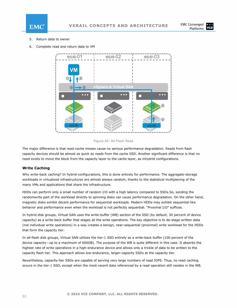
VXRAIL CONCEPTS AND ARCHITECTURE
52 © 2016 VCE COMPANY, LLC. ALL RIGHTS RESERVED.
5. Return data to owner
6. Complete read and return data to VM
Figure 49: All-Flash Read
The major difference is that read-cache misses cause no serious performance degradation. Reads from flash
capacity devices should be almost as quick as reads from the cache SSD. Another significant difference is that no
need exists to move the block from the capacity layer to the cache layer, as inhybrid configurations.
Write Caching
Why write-back caching? In hybrid-configurations, this is done entirely for performance. The aggregate-storage
workloads in virtualized infrastructures are almost always random, thanks to the statistical multiplexing of the
many VMs and applications that share the infrastructure.
HDDs can perform only a small number of random I/O with a high latency compared to SSDs.So, sending the
randomwrite part of the workload directly to spinning disks can cause performance degradation. On the other hand,
magnetic disks exhibit decent performance for sequential workloads. Modern HDDs may exhibit sequential-like
behavior and performance even when the workload is not perfectly sequential. ―Proximal I/O‖ suffices.
In hybrid disk groups, Virtual SAN uses the write-buffer (WB) section of the SSD (by default, 30 percent of device
capacity) as a write-back buffer that stages all the write operations. The key objective is to de-stage written data
(not individual write operations) in a way creates a benign, near-sequential (proximal) write workload for the HDDs
that form the capacity tier.
In all-flash disk groups, Virtual SAN utilizes the tier-1 SSD entirely as a write-back buffer (100 percent of the
device capacity—up to a maximum of 600GB). The purpose of the WB is quite different in this case. It absorbs the
highest rate of write operations in a high-endurance device and allows only a trickle of data to be written to the
capacity flash tier. This approach allows low-endurance, larger-capacity SSDs at the capacity tier.
Nevertheless, capacity-tier SSDs are capable of serving very large numbers of read IOPS. Thus, no read caching
occurs in the tier-1 SSD, except when the most-recent data referenced by a read operation still resides in the WB.
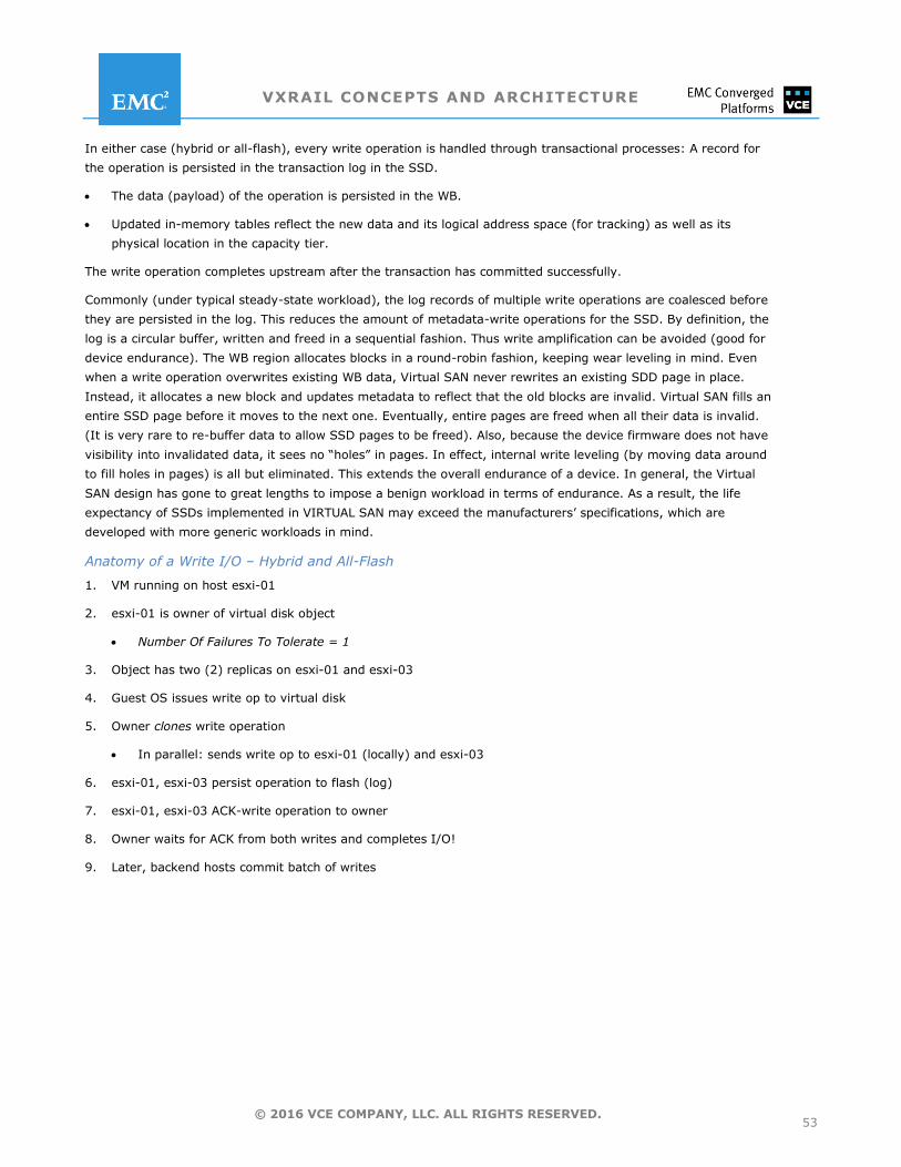
VXRAIL CONCEPTS AND ARCHITECTURE
53 © 2016 VCE COMPANY, LLC. ALL RIGHTS RESERVED.
In either case (hybrid or all-flash), every write operation is handled through transactional processes: A record for
the operation is persisted in the transaction log in the SSD.
The data (payload) of the operation is persisted in the WB.
Updated in-memory tables reflect the new data and its logical address space (for tracking) as well as its
physical location in the capacity tier.
The write operation completes upstream after the transaction has committed successfully.
Commonly (under typical steady-state workload), the log records of multiple write operations are coalesced before
they are persisted in the log. This reduces the amount of metadata-write operations for the SSD. By definition, the
log is a circular buffer, written and freed in a sequential fashion. Thus write amplification can be avoided (good for
device endurance). The WB region allocates blocks in a round-robin fashion, keeping wear leveling in mind. Even
when a write operation overwrites existing WB data, Virtual SAN never rewrites an existing SDD page in place.
Instead, it allocates a new block and updates metadata to reflect that the old blocks are invalid. Virtual SAN fills an
entire SSD page before it moves to the next one. Eventually, entire pages are freed when all their data is invalid.
(It is very rare to re-buffer data to allow SSD pages to be freed). Also, because the device firmware does not have
visibility into invalidated data, it sees no ―holes‖ in pages. In effect, internal write leveling (by moving data around
to fill holes in pages) is all but eliminated. This extends the overall endurance of a device. In general, the Virtual
SAN design has gone to great lengths to impose a benign workload in terms of endurance. As a result, the life
expectancy of SSDs implemented in VIRTUAL SAN may exceed the manufacturers’ specifications, which are
developed with more generic workloads in mind.
Anatomy of a Write I/O – Hybrid and All-Flash
1. VM running on host esxi-01
2. esxi-01 is owner of virtual disk object
Number Of Failures To Tolerate = 1
3. Object has two (2) replicas on esxi-01 and esxi-03
4. Guest OS issues write op to virtual disk
5. Owner clones write operation
In parallel: sends write op to esxi-01 (locally) and esxi-03
6. esxi-01, esxi-03 persist operation to flash (log)
7. esxi-01, esxi-03 ACK-write operation to owner
8. Owner waits for ACK from both writes and completes I/O!
9. Later, backend hosts commit batch of writes
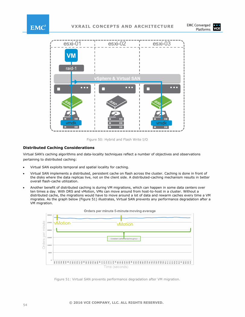
VXRAIL CONCEPTS AND ARCHITECTURE
54 © 2016 VCE COMPANY, LLC. ALL RIGHTS RESERVED.
Figure 50: Hybrid and Flash Write I/O
Distributed Caching Considerations
Virtual SAN’s caching algorithms and data-locality techniques reflect a number of objectives and observations
pertaining to distributed caching:
Virtual SAN exploits temporal and spatial locality for caching.
Virtual SAN implements a distributed, persistent cache on flash across the cluster. Caching is done in front of the disks where the data replicas live, not on the client side. A distributed-caching mechanism results in better overall flash-cache utilization.
Another benefit of distributed caching is during VM migrations, which can happen in some data centers over ten times a day. With DRS and vMotion, VMs can move around from host-to-host in a cluster. Without a distributed cache, the migrations would have to move around a lot of data and rewarm caches every time a VM migrates. As the graph below (Figure 51) illustrates, Virtual SAN prevents any performance degradation after a VM migration.
Figure 51: Virtual SAN prevents performance degradation after VM migration.
VXRAIL CONCEPTS AND ARCHITECTURE
55 © 2016 VCE COMPANY, LLC. ALL RIGHTS RESERVED.
The network introduces a small latency when accessing data on another host. Typical latencies in 10GbE networks range from 5 to50 microseconds. Typical latencies of a flash drive, accessed through a SCSI layer, are near 1ms for small (4K) I/O blocks. So, for the majority of the I/O executed in the system, the network impact adds near 0.1 percent to the latency.
Few workloads are actually cache-friendly, meaning that they don’t take advantage of the way small increases in cache size can significantly increase the rate of I/O. These workloads can benefit from local cache.
VirtualSAN works with a View Accelerator (deduplicated, in-memory read cache), which is notably effective for VDI use cases. Remember also that Virtual SAN 6.2 features client cache that leverages DRAM memory local to the virtual machine to accelerate read performance. The amount of memory allocated is anywhere from 0.4 percent to 1GB per host.
Virtual SAN High Availability and Fault Domains
Virtual SAN policy attributes establish parameters to protect against host failures, but they may not be the most
effective or efficient way to build tolerance for events like rack failures. This section surveys the availability
solutions for Virtual SAN clusters on the VxRail Appliance. It starts out by looking at the availability implications on
small VxRail Appliance deployments with fewer than four nodes.
Limitations of Two- and Three-Node Configurations
Currently, VxRail Appliance clusters a minimum of four nodes. If ―start small‖ the ideal for scalability, why not begin
even smaller than the four-node cluster? Virtual SAN supports a three-node cluster, but IT shops that deploy it
needs to understand the trade-off between the cost of the hardware and software components and the degree of
availability that the configuration provides. Two- and three-node configurations can behave differently from
configurations with at least four nodes. In particular, the system can come up short in the event of a failure. Such
small clusters have slim resources—certainly not enough to rebuild components on another host and automatically
restore fault tolerance. Also two-node and three-node configurations affect VM uptime during certain host-
maintenance operations that require data migration to another host.
Recall that Virtual SAN replication requires two copies of data and a witness—all of which reside on a different host.
In configurations with fewer than four nodes,that’s a problem. At best they can only tolerate one failure. If a node
fails, Virtual SAN can neither rebuild components nor provision new VMs that tolerate failures until the failed node
is replaced.When the applications require maximum availability, both for planned and unplanned outage scenarios,
a configuration with at least four nodes is recommended.
That said, VCE is planning a two-node VxRail Appliance for the near future. The two-node deployment is targeted at
ROBO locations where a small witness VM can reside in the central data center (1+1+1) or in the cloud. Each of the
nodes is a failure domain. The witness VM requires two vCPUs, 8GB of memory, 15GB of capacity, and 10GB for
caching.
On larger enterprise deployments, a three- or four-node Virtual SAN cluster could be deployed in the central data
center to host all the witnesses (as in Figure 52 below). All sites could be managed centrally by a single instance of
vCenter. (vSphere limitations apply: 1,000 hosts per vCenter, etc.)
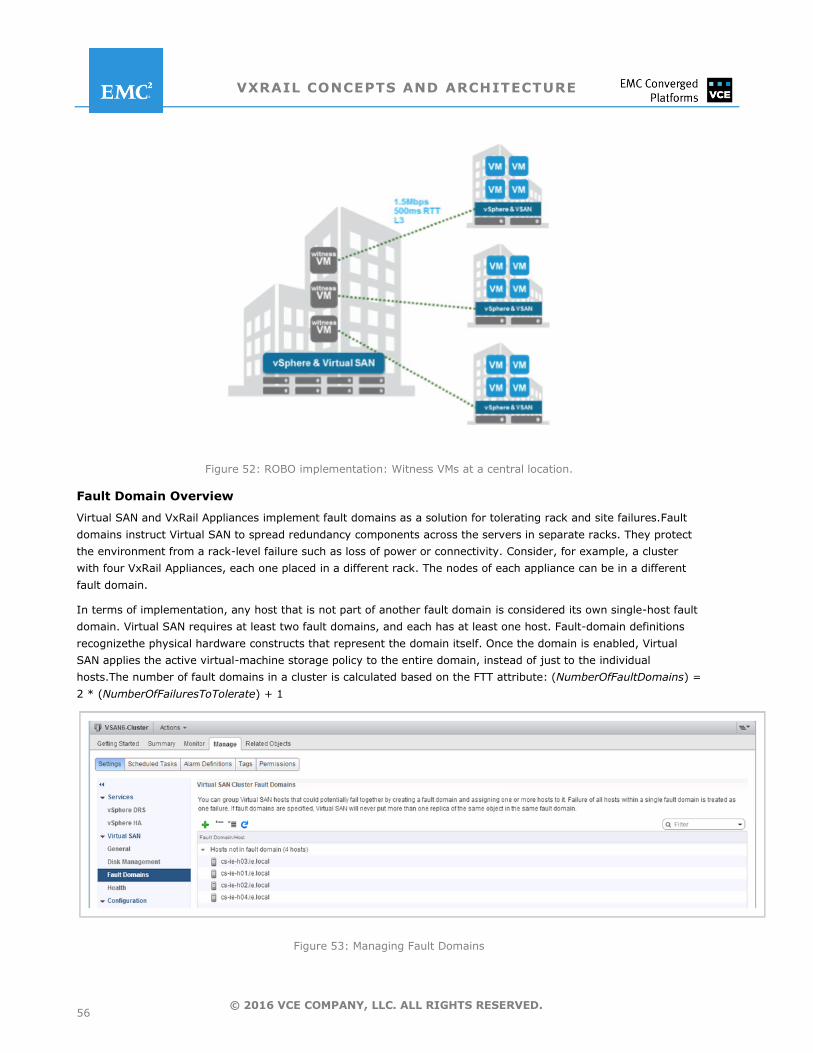
VXRAIL CONCEPTS AND ARCHITECTURE
56 © 2016 VCE COMPANY, LLC. ALL RIGHTS RESERVED.
Figure 52: ROBO implementation: Witness VMs at a central location.
Fault Domain Overview
Virtual SAN and VxRail Appliances implement fault domains as a solution for tolerating rack and site failures.Fault
domains instruct Virtual SAN to spread redundancy components across the servers in separate racks. They protect
the environment from a rack-level failure such as loss of power or connectivity. Consider, for example, a cluster
with four VxRail Appliances, each one placed in a different rack. The nodes of each appliance can be in a different
fault domain.
In terms of implementation, any host that is not part of another fault domain is considered its own single-host fault
domain. Virtual SAN requires at least two fault domains, and each has at least one host. Fault-domain definitions
recognizethe physical hardware constructs that represent the domain itself. Once the domain is enabled, Virtual
SAN applies the active virtual-machine storage policy to the entire domain, instead of just to the individual
hosts.The number of fault domains in a cluster is calculated based on the FTT attribute: (NumberOfFaultDomains) =
2 * (NumberOfFailuresToTolerate) + 1
Figure 53: Managing Fault Domains
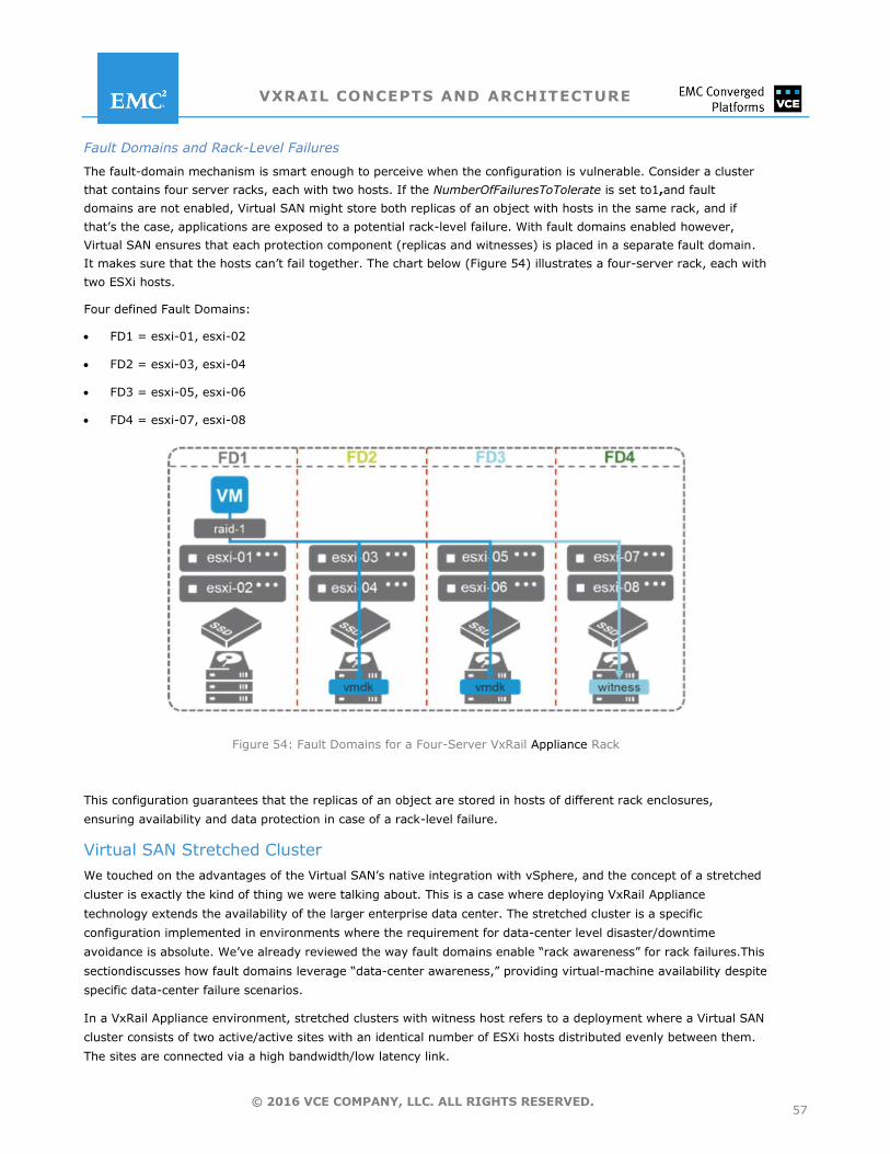
VXRAIL CONCEPTS AND ARCHITECTURE
57 © 2016 VCE COMPANY, LLC. ALL RIGHTS RESERVED.
Fault Domains and Rack-Level Failures
The fault-domain mechanism is smart enough to perceive when the configuration is vulnerable. Consider a cluster
that contains four server racks, each with two hosts. If the NumberOfFailuresToTolerate is set to1,and fault
domains are not enabled, Virtual SAN might store both replicas of an object with hosts in the same rack, and if
that’s the case, applications are exposed to a potential rack-level failure. With fault domains enabled however,
Virtual SAN ensures that each protection component (replicas and witnesses) is placed in a separate fault domain.
It makes sure that the hosts can’t fail together. The chart below (Figure 54) illustrates a four-server rack, each with
two ESXi hosts.
Four defined Fault Domains:
FD1 = esxi-01, esxi-02
FD2 = esxi-03, esxi-04
FD3 = esxi-05, esxi-06
FD4 = esxi-07, esxi-08
Figure 54: Fault Domains for a Four-Server VxRail Appliance Rack
This configuration guarantees that the replicas of an object are stored in hosts of different rack enclosures,
ensuring availability and data protection in case of a rack-level failure.
Virtual SAN Stretched Cluster
We touched on the advantages of the Virtual SAN’s native integration with vSphere, and the concept of a stretched
cluster is exactly the kind of thing we were talking about. This is a case where deploying VxRail Appliance
technology extends the availability of the larger enterprise data center. The stretched cluster is a specific
configuration implemented in environments where the requirement for data-center level disaster/downtime
avoidance is absolute. We’ve already reviewed the way fault domains enable ―rack awareness‖ for rack failures.This
sectiondiscusses how fault domains leverage ―data-center awareness,‖ providing virtual-machine availability despite
specific data-center failure scenarios.
In a VxRail Appliance environment, stretched clusters with witness host refers to a deployment where a Virtual SAN
cluster consists of two active/active sites with an identical number of ESXi hosts distributed evenly between them.
The sites are connected via a high bandwidth/low latency link.
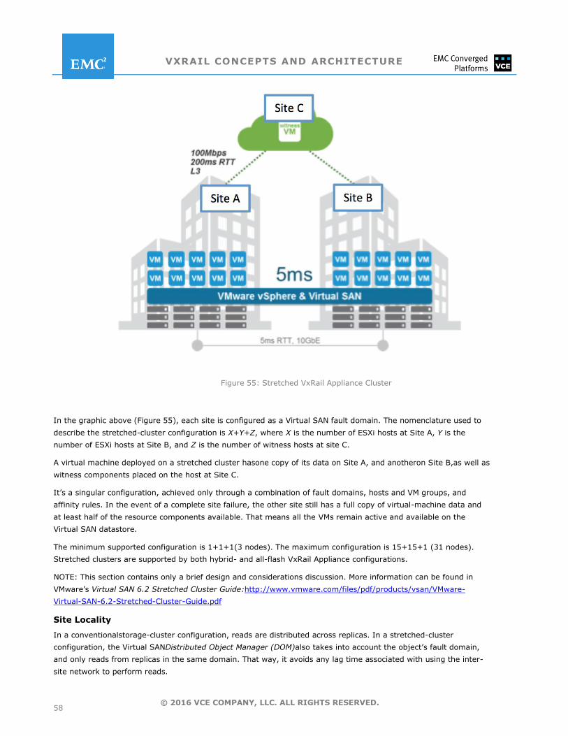
VXRAIL CONCEPTS AND ARCHITECTURE
58 © 2016 VCE COMPANY, LLC. ALL RIGHTS RESERVED.
Figure 55: Stretched VxRail Appliance Cluster
In the graphic above (Figure 55), each site is configured as a Virtual SAN fault domain. The nomenclature used to
describe the stretched-cluster configuration is X+Y+Z, where X is the number of ESXi hosts at Site A, Y is the
number of ESXi hosts at Site B, and Z is the number of witness hosts at site C.
A virtual machine deployed on a stretched cluster hasone copy of its data on Site A, and anotheron Site B,as well as
witness components placed on the host at Site C.
It’s a singular configuration, achieved only through a combination of fault domains, hosts and VM groups, and
affinity rules. In the event of a complete site failure, the other site still has a full copy of virtual-machine data and
at least half of the resource components available. That means all the VMs remain active and available on the
Virtual SAN datastore.
The minimum supported configuration is 1+1+1(3 nodes). The maximum configuration is 15+15+1 (31 nodes).
Stretched clusters are supported by both hybrid- and all-flash VxRail Appliance configurations.
NOTE: This section contains only a brief design and considerations discussion. More information can be found in
VMware’s Virtual SAN 6.2 Stretched Cluster Guide:http://www.vmware.com/files/pdf/products/vsan/VMware-
Virtual-SAN-6.2-Stretched-Cluster-Guide.pdf
Site Locality
In a conventionalstorage-cluster configuration, reads are distributed across replicas. In a stretched-cluster
configuration, the Virtual SANDistributed Object Manager (DOM)also takes into account the object’s fault domain,
and only reads from replicas in the same domain. That way, it avoids any lag time associated with using the inter-
site network to perform reads.
VXRAIL CONCEPTS AND ARCHITECTURE
59 © 2016 VCE COMPANY, LLC. ALL RIGHTS RESERVED.
Networking
Both Layer-2 (same subnet) and Layer-3 (routed) configurations areusedfor stretched-cluster deployments. A
Layer-2 connection should exist between data sites, and Layer-3 connection between the witness and the data
sites.
The bandwidth between data sites depends on workloads, but VCE recommends a minimum of 10Gbps for VxRail
Appliances, and that should accommodate the stretched cluster. (In two-node ROBO configurations, dedicated
1Gbps may suffice, but it still depends on workload activity.) The supported latency for witness hosts is up to
500ms RTT and a bandwidth of 2Mbps for every 1,000 Virtual SAN objects. Also bear in mind that the latency
between data sites should be no greater than 5ms, with the estimated distance for a 5ms RTT is 500km or about
310miles.
Stretched-Cluster Heartbeats and Site Bias
Stretched cluster configurations effectively have three fault domains. The first functions as the preferred data site,
the second is the secondary data site, and the third is simply the witness host site.
The Virtual SAN master node is placed on the preferred site and the Virtual SAN backup node is placed on the
secondary site. As long as nodes (ESXi hosts) are available in the preferred site, then a master is always selected
from one of the nodes on this site—similarly for the secondary site, as long as nodes are available on the secondary
site.
The master node and the backup node send heartbeats every second. If heartbeat communication is lost for five
consecutive heartbeats (five seconds),the witness is deemed to have failed. If the witness has suffered a
permanent failure, a new witness host can be configured and added to the cluster. Preferred sites gain ownership in
case of a partition.
After a complete failure, both the master and the backup end up at the sole remaining live site. Once the failed site
returns, it continues with its designated role as preferred or secondary, and the master and secondary migrate to
their respective locations.
vSphere HA settings for Stretched Cluster
Host monitoring is enabled by default in all VxRail Appliance deployments, including of course stretched-cluster configurations. This feature also uses network heartbeat to determine the status of hosts participating in the cluster. It indicates a possible need for remediation, such as restarting virtual machines on other cluster nodes.
Configuring admission control ensures that vSphere HA has sufficient available resources to restart virtual machines after a failure. This may be even more significant in a stretched cluster than it is in a single-site cluster, because it makes the entire, multi-site infrastructure resilient.Workload availability is perhaps the primary motivation behind most stretched-cluster implementations.
The deployment needs sufficient capacity to accommodate full-site failure. Since the stretched cluster equally divides the number of ESXi hosts between sites, VCE recommends configuring the admission-control policy to
50 percent for both CPU and memory to ensure that all workloads can be restarted by vSphere HA.
Snapshots
Snapshots have been around for a while as a means of capturing the state of system at a particular point in time
(PIT), so that it can be rolled back to that state if need be after a crash. In the case of the VxRail Appliance
solution, administrators can create, roll back, or delete VM snapshots using the Snapshot Manager in the vSphere
Web client. Each VM supports a chain of up to 32 snapshots.
A virtual machine snapshot generally includes the settings (.nvram and .vmx) and power state, state of all the
VM’s associated disks, and optionally, the memory state. Specifically, each snapshot includes:
Delta disk:
VXRAIL CONCEPTS AND ARCHITECTURE
60 © 2016 VCE COMPANY, LLC. ALL RIGHTS RESERVED.
o The state of the virtual disk at the time the snapshot is taken is preserved. When this occurs, the guest OS is unable write to its .vmdk file. Instead, changes are captured in an alternate file named VM_name-delta.vmdk.
Memory-state file:
o VM_name-Snapshot#.vmsn, where #is the next number in the sequence, starting with 1. This file holds the memory state since the snapshot was taken. If memory is captured, the size of this file is the size of the virtual machine’s maximum memory. If memory is not captured, the file is much smaller.
Disk-descriptor file:
o VM_name-00000#.vmdk, a small text file that contains information about the snapshot.
Snapshot-delta file:
o VM_name-00000#-delta.vmdk, which contains the changes to the virtual disk’s data at the time the snapshot was taken.
VM_name.vmsd:
o This snapshot list file is created when virtual machine itself is deployed. It maintains VM snapshot information that goes into a snapshot list in the vSphere Web Client. This information includes the name of the snapshot .vmsn file and the name of the virtual-disk file.
The snapshot state uses a .vmsn extension and stores the requisite VM information at the time of the snapshot.
Each new VM snapshot generates a new .vmsn file. The size of this file varies, based on the options selected during
creation. For example, including the memory state of the virtual machine increases the size of the .vmsn file.
Ittypically contains the name of the VMDK, the display name and description, and an identifier for each snapshot.
Other files might also exist. For example, a snapshot of a powered-on virtual machine has an associated
snapshot_name_number.vmem file that contains the main memory of the guest OS, saved as part of the
snapshot.
A quiesce option is available to maintain consistent point-in-time copies for powered-on VMs. VMware tools may
use their own sync driver or use Microsoft’s Volume Shadow Copy Service (VSS) to quiesce not only the guest OS
files system, but also any Microsoft applications that understand VSS directives.
How Snapshots Work
Virtual SAN snapshots use an efficient, on-disk Virtual SANSparse format. When a base-disk snapshot is taken, it
creates a child delta disk. The parent functions as a static, PIT copy. Meanwhile the child delta starts a snapshot
chain, recording the virtual-machine write history. The delta disk snapshot object is made up of a set of grains,
where each grain is a block of sectors containing virtual-disk data. The deltas keep only changed grains, which
makes them space efficient.
In the diagram below (Figure56), the base disk object is called Disk.vmdk and sits at the bottom of the chain. The
chain includes three snapshot objects (Disk-001.vmdk, Disk-002.vmdk and Disk-003.vmdk) that have been
taken at various intervals. Various guest-OS writes have also occurred at various intervals, leading to changes in
snapshot deltas.
Base object writes to grains 1,2,3, and 5,
Delta object Disk-001 writes to grains 1 and 4
Delta object Disk-002 writes to grains 2 and 4
Delta object Disk-003 writes to grains 1 and 6
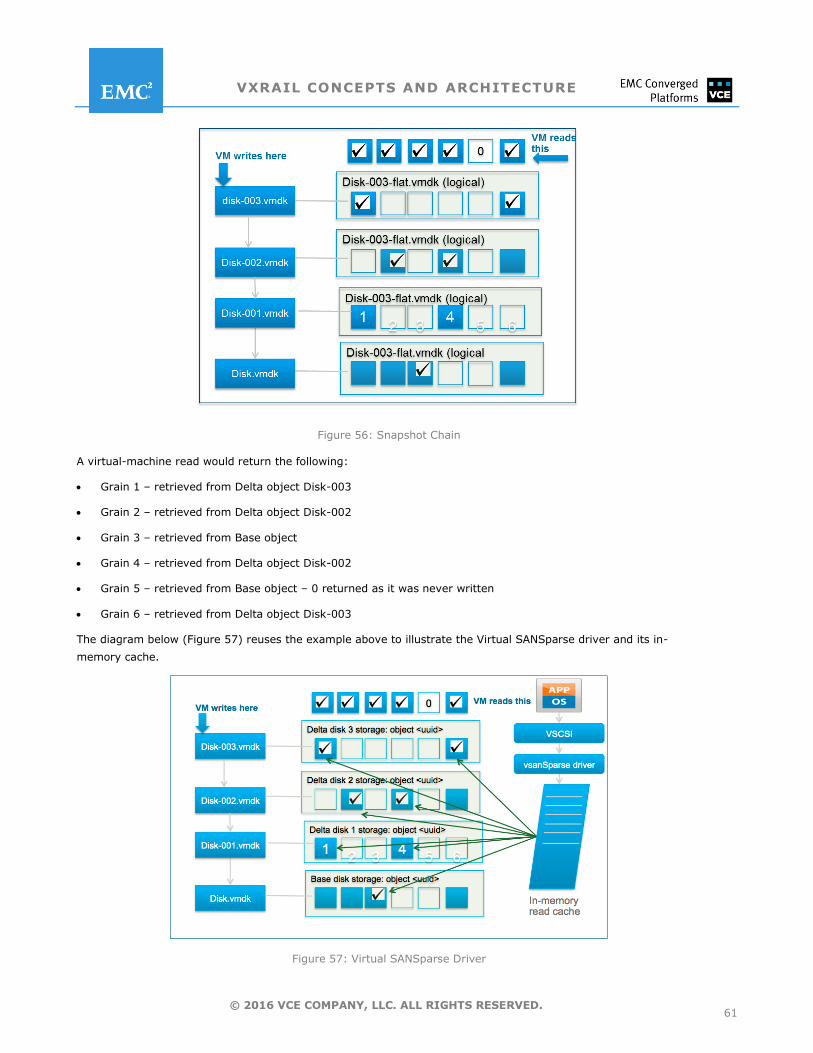
VXRAIL CONCEPTS AND ARCHITECTURE
61 © 2016 VCE COMPANY, LLC. ALL RIGHTS RESERVED.
Figure 56: Snapshot Chain
A virtual-machine read would return the following:
Grain 1 – retrieved from Delta object Disk-003
Grain 2 – retrieved from Delta object Disk-002
Grain 3 – retrieved from Base object
Grain 4 – retrieved from Delta object Disk-002
Grain 5 – retrieved from Base object – 0 returned as it was never written
Grain 6 – retrieved from Delta object Disk-003
The diagram below (Figure 57) reuses the example above to illustrate the Virtual SANSparse driver and its in-
memory cache.
Figure 57: Virtual SANSparse Driver
VXRAIL CONCEPTS AND ARCHITECTURE
62 © 2016 VCE COMPANY, LLC. ALL RIGHTS RESERVED.
When a guest OS sends a write request, the Virtual SANSparse driver writes the data to the top-most object in the
snapshot chain and updates its in-memory read cache. On subsequent reads, the Virtual SANSparse references the
in-memory read cache to determine which delta (or deltas) to read. The read requests are sent in parallel to all
deltas that have the necessary data.
Managing Snapshots
Administrators use the Snapshot Manager to review active virtual-machine snapshots and perform limited
management operations, including
Delete, which commits snapshot data to its parent snapshot
Delete All, which removes all the snapshots, including the parent
Revert To, which rolls back to a referenced snapshot so that it becomes the current snapshot
Note that deleting a snapshot consolidates the changes between snapshots and previous disk states. It also writes
to the parent disk all data from the delta disk and the deleted snapshot. When the parent is deleted, all changes
merge with the base VMDK.
Administrators also should remember to monitor read cache, because snapshots—used extensively—can consume
RC at a higher-than-optimal rate.
NOTE: For full details regarding VxRail Appliance snapshot technology, refer to Virtual SANSparse – Tech Note for
Virtual SAN 6.0 Snapshots at https://www.vmware.com/files/pdf/products/ SAN
Deduplication and Compression
Many IT sites want their storage solution to include data-reduction technology. For some, it’s more of a
requirement than for others. Naturally, environments with highly redundant data—full-clone virtual desktops for
instance, or homogenous-server operating systems—benefit the most from deduplication. Likewise, compression
makes more of an impact on resources that compress well: Text, bitmap, and program files. For these
environments, deduplication and compression can dramatically reduce the amount of physical storage consumed,
resulting in a lower total cost of ownership.
It may sound obvious, but considering that deduplication and compression algorithms consume CPU and memory,
it’simportant to verify that the stored data in question is actually compressible. Sometimes data has already been
compressed—for example, certain graphics formats and video files, or encrypted files. These may ultimately yield
little or no reduction at all in storage consumption from compression.
Advantages of Data-Reduction Technology
Several years ago, when NAND flash started to appear in storage arrays, a gulf separated HDDs from flash drives in
terms of cost/GB. Flash cost fifteen times more than magnetic devices. The introduction of deduplication and
compression techniques in the data path helped create the market segment of all-flash arrays (AFAs), which were
effective in reducing the cost of flashfor tier-1 applications, despite the high cost of a global-lookup table for
fingerprints.
More recently, the cost of NAND flash has dropped 50 percent, and an all-flash configuration is suddenly very
attractive for more than just tier-1 workloads. It also has the opportunity to better balance the data-reduction
target and the consumption of CPU against memory and network resources on an appliance like VxRail Appliance.
This is precisely where data reduction benefits VxRail Appliance customers. The appliance includes in-line
deduplication and compression at a disk-group level.
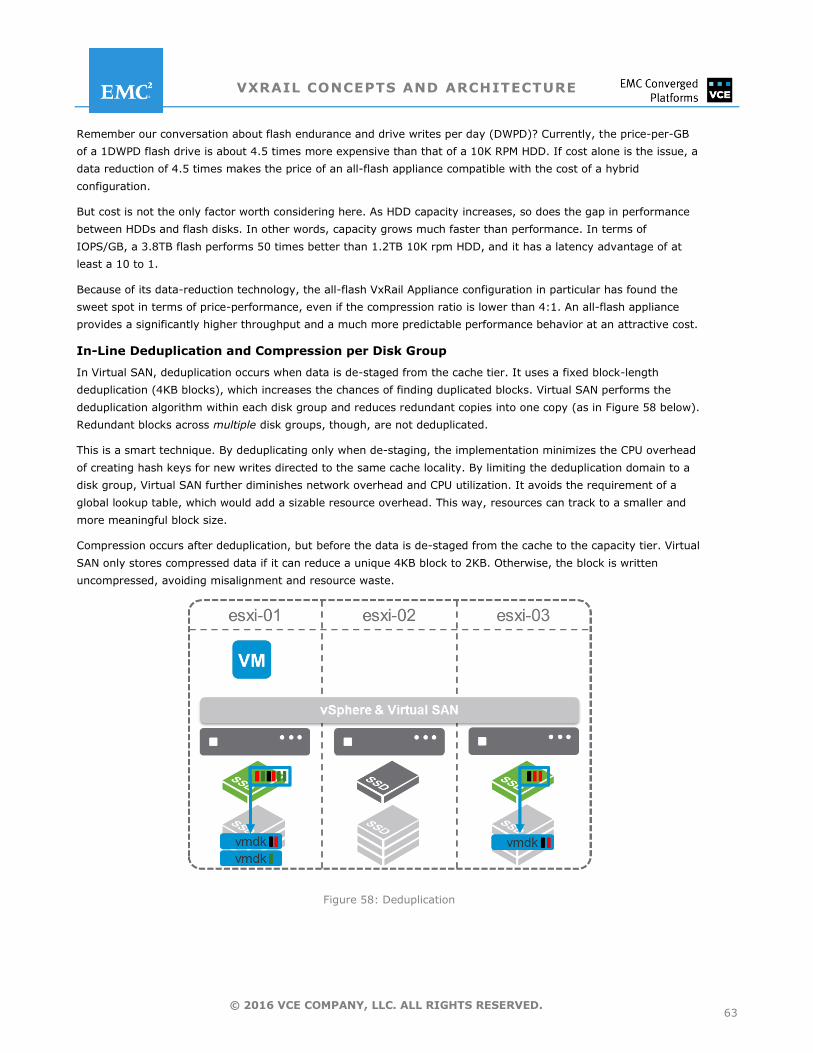
VXRAIL CONCEPTS AND ARCHITECTURE
63 © 2016 VCE COMPANY, LLC. ALL RIGHTS RESERVED.
Remember our conversation about flash endurance and drive writes per day (DWPD)? Currently, the price-per-GB
of a 1DWPD flash drive is about 4.5 times more expensive than that of a 10K RPM HDD. If cost alone is the issue, a
data reduction of 4.5 times makes the price of an all-flash appliance compatible with the cost of a hybrid
configuration.
But cost is not the only factor worth considering here. As HDD capacity increases, so does the gap in performance
between HDDs and flash disks. In other words, capacity grows much faster than performance. In terms of
IOPS/GB, a 3.8TB flash performs 50 times better than 1.2TB 10K rpm HDD, and it has a latency advantage of at
least a 10 to 1.
Because of its data-reduction technology, the all-flash VxRail Appliance configuration in particular has found the
sweet spot in terms of price-performance, even if the compression ratio is lower than 4:1. An all-flash appliance
provides a significantly higher throughput and a much more predictable performance behavior at an attractive cost.
In-Line Deduplication and Compression per Disk Group
In Virtual SAN, deduplication occurs when data is de-staged from the cache tier. It uses a fixed block-length
deduplication (4KB blocks), which increases the chances of finding duplicated blocks. Virtual SAN performs the
deduplication algorithm within each disk group and reduces redundant copies into one copy (as in Figure 58 below).
Redundant blocks across multiple disk groups, though, are not deduplicated.
This is a smart technique. By deduplicating only when de-staging, the implementation minimizes the CPU overhead
of creating hash keys for new writes directed to the same cache locality. By limiting the deduplication domain to a
disk group, Virtual SAN further diminishes network overhead and CPU utilization. It avoids the requirement of a
global lookup table, which would add a sizable resource overhead. This way, resources can track to a smaller and
more meaningful block size.
Compression occurs after deduplication, but before the data is de-staged from the cache to the capacity tier. Virtual
SAN only stores compressed data if it can reduce a unique 4KB block to 2KB. Otherwise, the block is written
uncompressed, avoiding misalignment and resource waste.
Figure 58: Deduplication
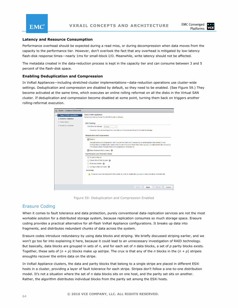
VXRAIL CONCEPTS AND ARCHITECTURE
64 © 2016 VCE COMPANY, LLC. ALL RIGHTS RESERVED.
Latency and Resource Consumption
Performance overhead should be expected during a read miss, or during decompression when data moves from the
capacity to the performance tier. However, don’t overlook the fact that any overhead is mitigated by low-latency
flash-disk response times—nearly 1ms for small-block I/O. Meanwhile, write latency should not be affected.
The metadata created in the data-reduction process is kept in the capacity tier and can consume between 3 and 5
percent of the flash-disk space.
Enabling Deduplication and Compression
In VxRail Appliances—including stretched-cluster implementations—data-reduction operations use cluster-wide
settings. Deduplication and compression are disabled by default, so they need to be enabled. (See Figure 59.) They
become activated at the same time, which executes an online rolling reformat on all the disks in the Virtual SAN
cluster. If deduplication and compression become disabled at some point, turning them back on triggers another
rolling-reformat execution.
Figure 59: Deduplication and Compression Enabled
Erasure Coding
When it comes to fault tolerance and data protection, purely conventional data-replication services are not the most
workable solution for a distributed storage system, because replication consumes so much storage space. Erasure
coding provides a practical alternative for all-flash VxRail Appliance configurations. It breaks up data into
fragments, and distributes redundant chunks of data across the system.
Erasure codes introduce redundancy by using data blocks and striping. We briefly discussed striping earlier, and we
won’t go too far into explaining it here, because it could lead to an unnecessary investigation of RAID technology.
But basically, data blocks are grouped in sets of n, and for each set of n data blocks, a set of p parity blocks exists.
Together, these sets of (n + p) blocks make up astripe. The crux is that any of the n blocks in the (n + p) stripeis
enoughto recover the entire data on the stripe.
In VxRail Appliance clusters, the data and parity blocks that belong to a single stripe are placed in different ESXi
hosts in a cluster, providing a layer of fault tolerance for each stripe. Stripes don’t follow a one-to-one distribution
model. It’s not a situation where the set of n data blocks sits on one host, and the parity set sits on another.
Rather, the algorithm distributes individual blocks from the parity set among the ESXi hosts.
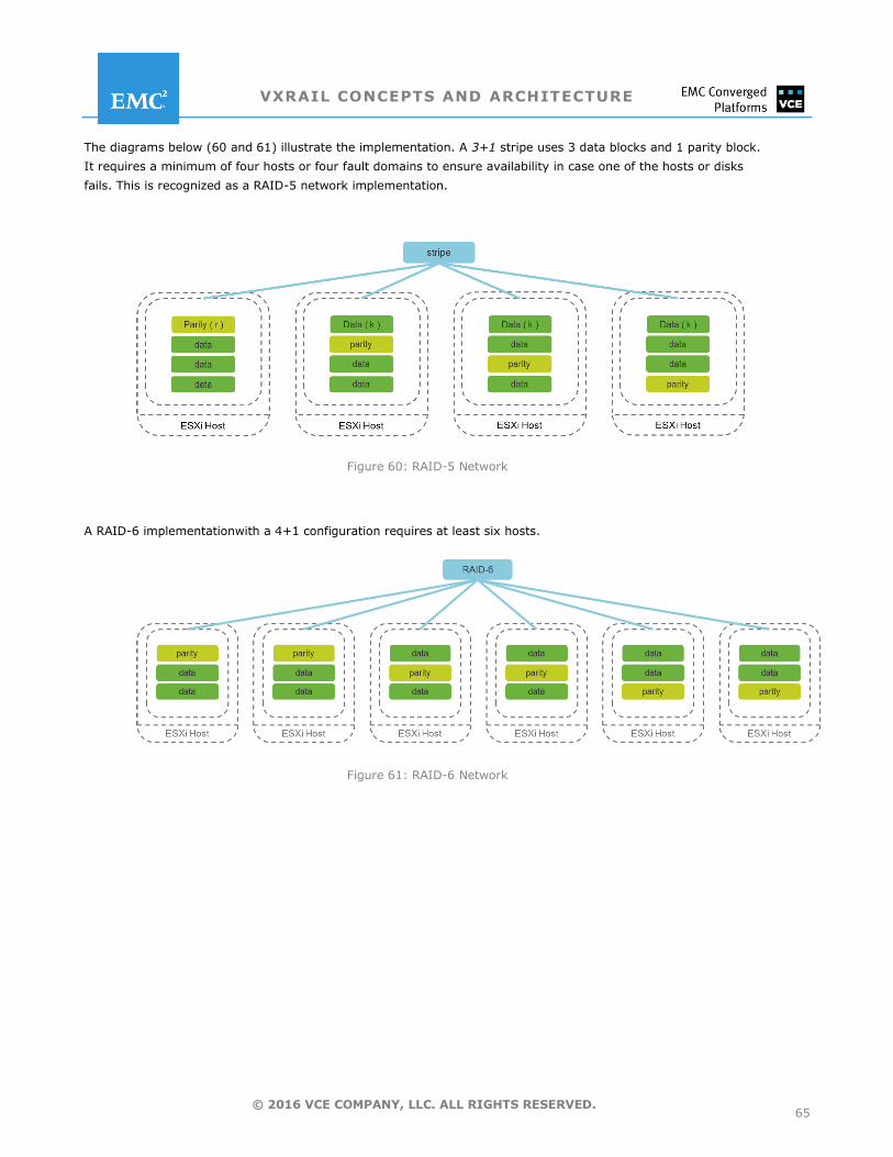
VXRAIL CONCEPTS AND ARCHITECTURE
65 © 2016 VCE COMPANY, LLC. ALL RIGHTS RESERVED.
The diagrams below (60 and 61) illustrate the implementation. A 3+1 stripe uses 3 data blocks and 1 parity block.
It requires a minimum of four hosts or four fault domains to ensure availability in case one of the hosts or disks
fails. This is recognized as a RAID-5 network implementation.
Figure 60: RAID-5 Network
A RAID-6 implementationwith a 4+1 configuration requires at least six hosts.
Figure 61: RAID-6 Network
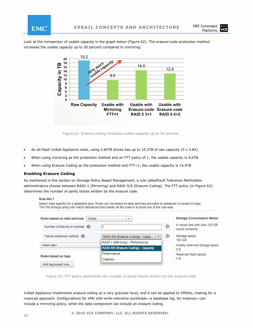
VXRAIL CONCEPTS AND ARCHITECTURE
66 © 2016 VCE COMPANY, LLC. ALL RIGHTS RESERVED.
Look at the comparison of usable capacity in the graph below (Figure 62). The erasure-code protection method
increases the usable capacity up to 50 percent compared to mirroring.
Figure 62: Erasure coding increases usable capacity up to 50 percent.
An all-flash VxRail Appliance node, using 3.84TB drives has up to 19.2TB of raw capacity (5 x 3.84).
When using mirroring as the protection method and an FTT policy of 1, the usable capacity is 9.6TB.
When using Erasure Coding as the protection method and FTT=1, the usable capacity is 14.4TB
Enabling Erasure Coding
As mentioned in the section on Storage Policy Based Management, a rule calledFault Tolerance Methodlets
administrators choose between RAID-1 (Mirroring) and RAID-5/6 (Erasure Coding). The FTT policy (in Figure 63)
determines the number of parity blocks written by the erasure code.
Figure 63: FTT policy determines the number of parity blocks written by the erasure code
VxRail Appliance implements erasure coding at a very granular level, and it can be applied to VMDKs, making for a
nuanced approach. Configurations for VMs with write-intensive workloads—a database log, for instance—can
include a mirroring policy, while the data component can include an erasure coding.
VXRAIL CONCEPTS AND ARCHITECTURE
67 © 2016 VCE COMPANY, LLC. ALL RIGHTS RESERVED.
Requirements
Erasure coding requires a minimum number of fault domains to ensure availability. (Remember that if no fault
domains have been defined, an individual host becomes fault domain.)
Overhead Issues (RAID-5 and RAID-6)
Erasure coding saves space, yes, but the cost is performance. Computing parity blocks consumes CPU cycles and
adds overhead to the network and disks, as does distributing data slices across multiple hosts. This extra activity
can affect latency and overall IOPS throughput.
The rebuild operation also adds overhead. In general, rebuild operations multiply the number of reads and network
transfers used for replication. A formula is available here, too. If, n refers to the number of blocks in a stripe, then
the rebuild operations cost n times that of ordinary replication. For a 3+1 stripe, that means three disk reads and
three network transfers for every one of conventional data-replication. The rebuild operation can also be invoked to
serve read requests for currently available data.
This additional I/0 is the primary reason why only all-flash VxRail Appliance configurations use erasure coding. The
rationale here is that the flash disks compensate for the extra I/O.
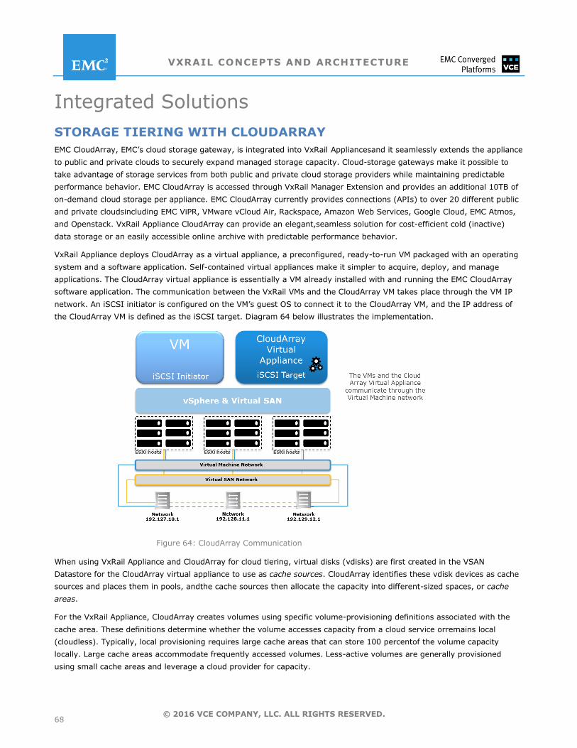
VXRAIL CONCEPTS AND ARCHITECTURE
68 © 2016 VCE COMPANY, LLC. ALL RIGHTS RESERVED.
Integrated Solutions
STORAGE TIERING WITH CLOUDARRAY
EMC CloudArray, EMC’s cloud storage gateway, is integrated into VxRail Appliancesand it seamlessly extends the appliance
to public and private clouds to securely expand managed storage capacity. Cloud-storage gateways make it possible to
take advantage of storage services from both public and private cloud storage providers while maintaining predictable
performance behavior. EMC CloudArray is accessed through VxRail Manager Extension and provides an additional 10TB of
on-demand cloud storage per appliance. EMC CloudArray currently provides connections (APIs) to over 20 different public
and private cloudsincluding EMC ViPR, VMware vCloud Air, Rackspace, Amazon Web Services, Google Cloud, EMC Atmos,
and Openstack. VxRail Appliance CloudArray can provide an elegant,seamless solution for cost-efficient cold (inactive)
data storage or an easily accessible online archive with predictable performance behavior.
VxRail Appliance deploys CloudArray as a virtual appliance, a preconfigured, ready-to-run VM packaged with an operating
system and a software application. Self-contained virtual appliances make it simpler to acquire, deploy, and manage
applications. The CloudArray virtual appliance is essentially a VM already installed with and running the EMC CloudArray
software application. The communication between the VxRail VMs and the CloudArray VM takes place through the VM IP
network. An iSCSI initiator is configured on the VM’s guest OS to connect it to the CloudArray VM, and the IP address of
the CloudArray VM is defined as the iSCSI target. Diagram 64 below illustrates the implementation.
Figure 64: CloudArray Communication
When using VxRail Appliance and CloudArray for cloud tiering, virtual disks (vdisks) are first created in the VSAN
Datastore for the CloudArray virtual appliance to use as cache sources. CloudArray identifies these vdisk devices as cache
sources and places them in pools, andthe cache sources then allocate the capacity into different-sized spaces, or cache
areas.
For the VxRail Appliance, CloudArray creates volumes using specific volume-provisioning definitions associated with the
cache area. These definitions determine whether the volume accesses capacity from a cloud service orremains local
(cloudless). Typically, local provisioning requires large cache areas that can store 100 percentof the volume capacity
locally. Large cache areas accommodate frequently accessed volumes. Less-active volumes are generally provisioned
using small cache areas and leverage a cloud provider for capacity.
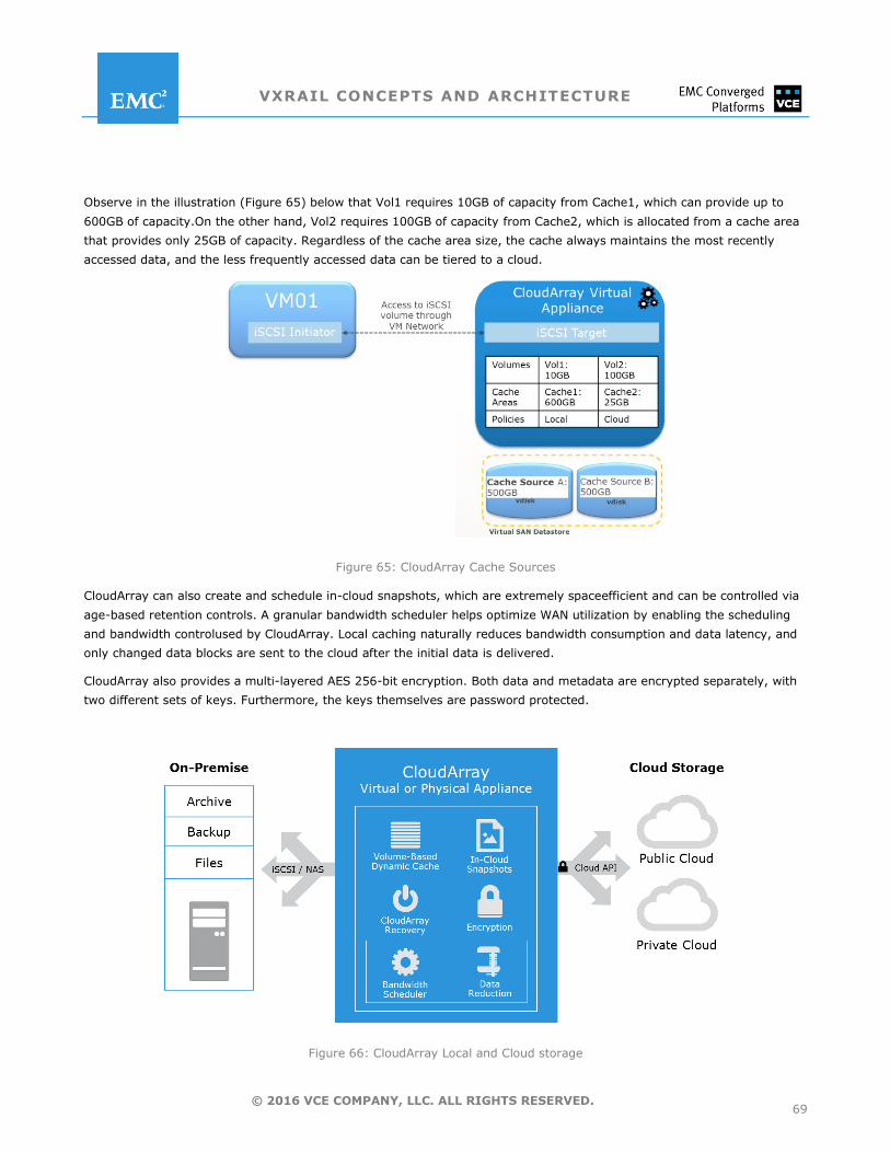
VXRAIL CONCEPTS AND ARCHITECTURE
69 © 2016 VCE COMPANY, LLC. ALL RIGHTS RESERVED.
Observe in the illustration (Figure 65) below that Vol1 requires 10GB of capacity from Cache1, which can provide up to
600GB of capacity.On the other hand, Vol2 requires 100GB of capacity from Cache2, which is allocated from a cache area
that provides only 25GB of capacity. Regardless of the cache area size, the cache always maintains the most recently
accessed data, and the less frequently accessed data can be tiered to a cloud.
Figure 65: CloudArray Cache Sources
CloudArray can also create and schedule in-cloud snapshots, which are extremely spaceefficient and can be controlled via
age-based retention controls. A granular bandwidth scheduler helps optimize WAN utilization by enabling the scheduling
and bandwidth controlused by CloudArray. Local caching naturally reduces bandwidth consumption and data latency, and
only changed data blocks are sent to the cloud after the initial data is delivered.
CloudArray also provides a multi-layered AES 256-bit encryption. Both data and metadata are encrypted separately, with
two different sets of keys. Furthermore, the keys themselves are password protected.
Figure 66: CloudArray Local and Cloud storage
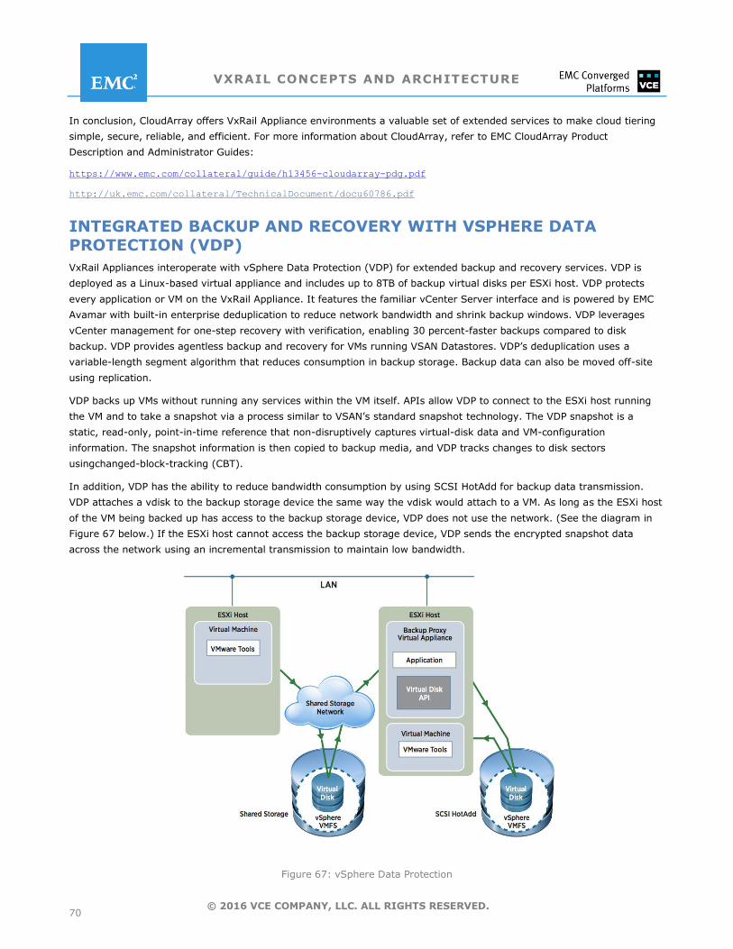
VXRAIL CONCEPTS AND ARCHITECTURE
70 © 2016 VCE COMPANY, LLC. ALL RIGHTS RESERVED.
In conclusion, CloudArray offers VxRail Appliance environments a valuable set of extended services to make cloud tiering
simple, secure, reliable, and efficient. For more information about CloudArray, refer to EMC CloudArray Product
Description and Administrator Guides:
https://www.emc.com/collateral/guide/h13456-cloudarray-pdg.pdf
http://uk.emc.com/collateral/TechnicalDocument/docu60786.pdf
INTEGRATED BACKUP AND RECOVERY WITH VSPHERE DATA PROTECTION (VDP)
VxRail Appliances interoperate with vSphere Data Protection (VDP) for extended backup and recovery services. VDP is
deployed as a Linux-based virtual appliance and includes up to 8TB of backup virtual disks per ESXi host. VDP protects
every application or VM on the VxRail Appliance. It features the familiar vCenter Server interface and is powered by EMC
Avamar with built-in enterprise deduplication to reduce network bandwidth and shrink backup windows. VDP leverages
vCenter management for one-step recovery with verification, enabling 30 percent-faster backups compared to disk
backup. VDP provides agentless backup and recovery for VMs running VSAN Datastores. VDP’s deduplication uses a
variable-length segment algorithm that reduces consumption in backup storage. Backup data can also be moved off-site
using replication.
VDP backs up VMs without running any services within the VM itself. APIs allow VDP to connect to the ESXi host running
the VM and to take a snapshot via a process similar to VSAN’s standard snapshot technology. The VDP snapshot is a
static, read-only, point-in-time reference that non-disruptively captures virtual-disk data and VM-configuration
information. The snapshot information is then copied to backup media, and VDP tracks changes to disk sectors
usingchanged-block-tracking (CBT).
In addition, VDP has the ability to reduce bandwidth consumption by using SCSI HotAdd for backup data transmission.
VDP attaches a vdisk to the backup storage device the same way the vdisk would attach to a VM. As long as the ESXi host
of the VM being backed up has access to the backup storage device, VDP does not use the network. (See the diagram in
Figure 67 below.) If the ESXi host cannot access the backup storage device, VDP sends the encrypted snapshot data
across the network using an incremental transmission to maintain low bandwidth.
Figure 67: vSphere Data Protection
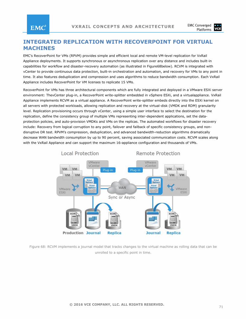
VXRAIL CONCEPTS AND ARCHITECTURE
71 © 2016 VCE COMPANY, LLC. ALL RIGHTS RESERVED.
INTEGRATED REPLICATION WITH RECOVERPOINT FOR VIRTUAL MACHINES
EMC’s RecoverPoint for VMs (RPVM) provides simple and efficient local and remote VM-level replication for VxRail
Appliance deployments. It supports synchronous or asynchronous replication over any distance and includes built-in
capabilities for workflow and disaster-recovery automation (as illustrated in Figure68below). RCVM is integrated with
vCenter to provide continuous data protection, built-in orchestration and automation, and recovery for VMs to any point in
time. It also features deduplication and compression and uses algorithms to reduce bandwidth consumption. Each VxRail
Appliance includes RecoverPoint for VM licenses to replicate 15 VMs.
RecoverPoint for VMs has three architectural components which are fully integrated and deployed in a VMware ESXi server
environment: ThevCenter plug-in, a RecoverPoint write-splitter embedded in vSphere ESXi, and a virtualappliance. VxRail
Appliance implements RCVM as a virtual appliance. A RecoverPoint write-splitter embeds directly into the ESXi kernel on
all servers with protected workloads, allowing replication and recovery at the virtual-disk (VMDK and RDM) granularity
level. Replication provisioning occurs through vCenter, using a simple user interface to select the destination for the
replication, define the consistency group of multiple VMs representing inter-dependent applications, set the data-
protection policies, and auto-provision VMDKs and VMs on the replicas. The automated workflows for disaster recovery
include: Recovery from logical corruption to any point, failover and failback of specific consistency groups, and non-
disruptive DR test. RPVM’s compression, deduplication, and advanced bandwidth-reduction algorithms dramatically
decrease WAN bandwidth consumption by up to 90 percent, saving associated communication costs. RCVM scales along
with the VxRail Appliance and can support the maximum 16-appliance configuration and thousands of VMs.
Figure 68: RCVM implements a journal model that tracks changes to the virtual machine as rolling data that can be
unrolled to a specific point in time.

VXRAIL CONCEPTS AND ARCHITECTURE
72 © 2016 VCE COMPANY, LLC. ALL RIGHTS RESERVED.
VxRail Appliance Use-Case Examples
VCE VxRail Hyper-Converged Infrastructure Appliances have been deployed successfully to fit many use cases. This
section describes two such use cases—one for a virtual desktop infrastructure (VDI) platform and one for a remote
office/branch office IT infrastructure platform. Each use case is then highlighted in a specific customer solution
implementation. These customers benefit from the simplicity and business value of the VxRail Appliance.
USE CASE: CREATE IT CERTAINTY FOR VIRTUAL DESKTOP
INFRASTRUCTURE (VDI)
VCE VxRail Appliances are the easiest, fastest, most affordable way to implement a high performance VDI infrastructure.
Rapidlydeploy an appliance that integrates market-leading compute, storage, virtualization, and management software
from EMC andVMware to set up a VDI infrastructure in minutes. Flexible configuration options and modular scalability
ensure that optimumperformance and capacity are always available whether you are deploying hundreds or thousands of
virtual desktops. The VxRail Appliance’s highly redundantarchitecture, integrated EMC data protection software, and non-
disruptive upgrades create certainty that virtualdesktops will always be available to end users and that the user
experience will always exceed expectations.VCE VxRail Appliances are a family of hyper-converged infrastructure (HCI)
appliances that include a full suite of industry-leadingdata services, including replication, backup, and recovery for data
protection. Built on the foundation of VMware Hyper-Converged Software and managedthrough the familiar VMware
vCenter interface, VxRail Appliances provide customers with a familiar experience that also allows them to take advantage
of the hallmark benefits of VCE—increased agility, simplified operations, and lower risk.
VxRail Appliance Advantages for VDI
Quick and easy automated deployment with power-on to VM creation in minutes and easy ongoing VM management
Scalability from 80 to 600 virtual desktops per appliance, and a maximum 9,600 desktops in a fully-populated VxRail Appliance cluster
One-click, non-disruptive patches and upgrades
Application uptime ensured through highly available VMware VSAN
Automated operational and disaster-recovery orchestration for VMs, including local and remote replication and continuous data protection with granular recovery to any point in time
VxRail Appliances enable customers to reduce VDI footprints, saving power and infrastructure costs while minimizing
administrativeburdens and lowering operational costs. The modular, just-in-time purchase approach enables predictable
evolution with a repeatable, simple, and agile means to scale on demand. VxRail Appliances can host virtual desktops from
VMware,Citrix, and other VDI vendors. Businesses can be confident that VxRail Appliances will meet performance and
capacity demands associated with desktop growth andapplication and user demands through continuous hardware and
software evolution. VxRail Appliances seamlessly integrate new enterpriseclass x86 and storage technologies and non-
disruptively update to the latest VMwaresoftware to ensure thatthe VDI deployment can continuously modernize to meet
business demands.
00002016
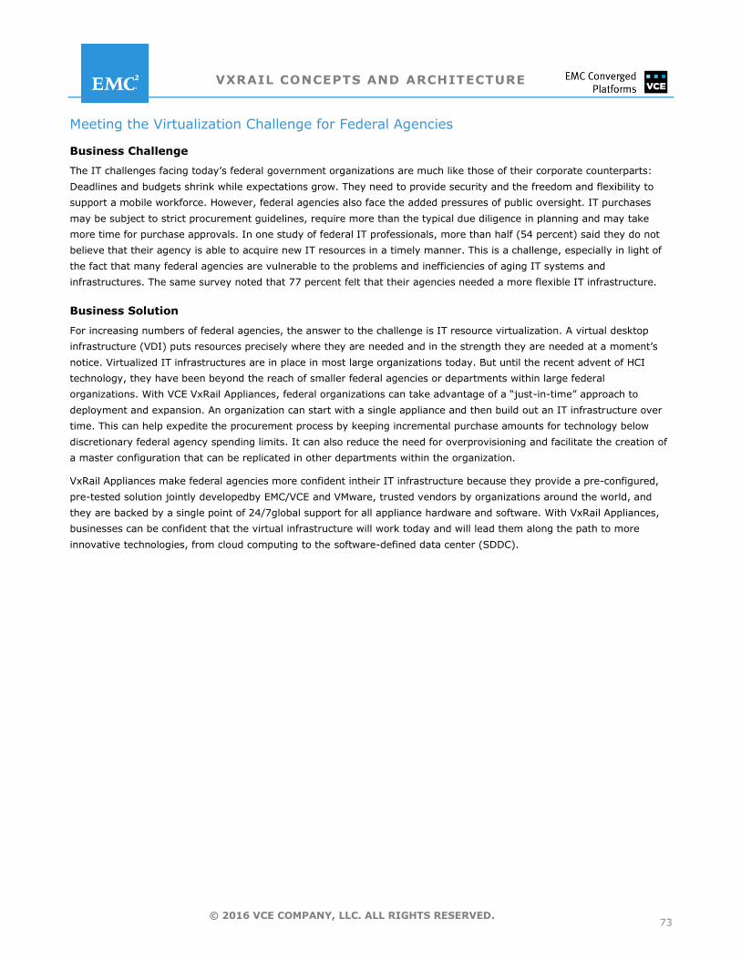
VXRAIL CONCEPTS AND ARCHITECTURE
73 © 2016 VCE COMPANY, LLC. ALL RIGHTS RESERVED.
Meeting the Virtualization Challenge for Federal Agencies
Business Challenge
The IT challenges facing today’s federal government organizations are much like those of their corporate counterparts:
Deadlines and budgets shrink while expectations grow. They need to provide security and the freedom and flexibility to
support a mobile workforce. However, federal agencies also face the added pressures of public oversight. IT purchases
may be subject to strict procurement guidelines, require more than the typical due diligence in planning and may take
more time for purchase approvals. In one study of federal IT professionals, more than half (54 percent) said they do not
believe that their agency is able to acquire new IT resources in a timely manner. This is a challenge, especially in light of
the fact that many federal agencies are vulnerable to the problems and inefficiencies of aging IT systems and
infrastructures. The same survey noted that 77 percent felt that their agencies needed a more flexible IT infrastructure.
Business Solution
For increasing numbers of federal agencies, the answer to the challenge is IT resource virtualization. A virtual desktop
infrastructure (VDI) puts resources precisely where they are needed and in the strength they are needed at a moment’s
notice. Virtualized IT infrastructures are in place in most large organizations today. But until the recent advent of HCI
technology, they have been beyond the reach of smaller federal agencies or departments within large federal
organizations. With VCE VxRail Appliances, federal organizations can take advantage of a ―just-in-time‖ approach to
deployment and expansion. An organization can start with a single appliance and then build out an IT infrastructure over
time. This can help expedite the procurement process by keeping incremental purchase amounts for technology below
discretionary federal agency spending limits. It can also reduce the need for overprovisioning and facilitate the creation of
a master configuration that can be replicated in other departments within the organization.
VxRail Appliances make federal agencies more confident intheir IT infrastructure because they provide a pre-configured,
pre-tested solution jointly developedby EMC/VCE and VMware, trusted vendors by organizations around the world, and
they are backed by a single point of 24/7global support for all appliance hardware and software. With VxRail Appliances,
businesses can be confident that the virtual infrastructure will work today and will lead them along the path to more
innovative technologies, from cloud computing to the software-defined data center (SDDC).
VXRAIL CONCEPTS AND ARCHITECTURE
74 © 2016 VCE COMPANY, LLC. ALL RIGHTS RESERVED.
USE CASE: SIMPLIFYING THE DISTRIBUTED ENTERPRISE ENVIRONMENT
Distributed Enterprises usually have a central IT staff that creates the overall business network architecture for the
enterprise, and also have many remote offices that are essential to running the business, normally with limited on-site
technical staff. However, the infrastructure and data at these distributed locations is mission critical. Typical important
operations found in distributed enterprises are warehousing and distribution, manufacturing of the company's core
products and mobile or remote life-saving operations like health clinics. Support responsibilities for these remote
operations usually fall to the central IT staff. According to Enterprise Strategy Group (ESG) in their 2015 research report
Remote Office/Branch Office Technology Trends, 72 percent of organizations intend to increase spending on remote office
IT infrastructure. In addition to the above challenges, footprint is an issue because remote locations, unlike data centers,
do not have the dedicated space, power, or cooling capabilities necessary for multiple servers running multiple
applications. This means remote organizations are much more sensitive to server sprawl. While some organizations may
look to the cloud to reduce server sprawl and centralize operations, in many cases that is not feasible. This is because
offices either are in remote locations with limited Internet service or have minimal WAN bandwidth and redundancy
available. So issues such as latency and availability become limiting factors. VCE VxRail Appliances are ideal for
consolidating multiple applications in a remote location onto a single high-performance and highly-available platform that
is easy to deploy and manage.
VCE VxRail Appliances that integrate compute, storage, virtualization, and management software from EMC and VMware
are theoptimal endpoints for the distributed enterprise. As an integral solution in the VCEconverged infrastructure
portfolio, VxRail Appliances can be monitored with VCE Vision™ Intelligent Operations, enabling IT to have visibility across
the distributed solution from the same single-pane-of-glass console used to manage the data center infrastructure. The
VxRail Appliance enables customers to consolidate multiple remote office applications onto a single appliance. VMware
VirtualSAN software integrated with flash or hybrid storage ensures the highest possible performance since Virtual SAN is
embedded inthe hypervisor and eliminates many data path bottlenecks. Simple deployment enables customers to be up
and running in 15minutes. The local team only needs to plug in the appliance and power it up. All other configuration can
be done remotely.In addition, the VxRail Appliance is the only HCI appliance on the market offering Quality of Service
(QoS) functionality thateliminates ―noisy neighbors.‖ This functionality makes it certain that multiple applications can be
hosted on the same appliance or inthe same cluster without performance impact.
VxRail Appliance Advantages for Distributed Enterprises
Tailor compute and capacity deployment for each remote location
Simple, standard set-up reduces IT skills needed at remote locations
Part of a complete portfolio of converged infrastructure core-to-edge solutions
Backup locally at the remote office or over the WAN to central data centers with RecoverPoint for VMs
Management and visibility across the distributed enterprise with VMware tools and VCE Vision™ software
VXRAIL CONCEPTS AND ARCHITECTURE
75 © 2016 VCE COMPANY, LLC. ALL RIGHTS RESERVED.
Meeting the Distributed Enterprise Challenge for State and Local Agencies
Business Challenge
For state and local agencies, the promises of new technology come with unique new challenges as well. New applications,
includingthose for remote and mobile computing, for example, can boost user productivity, but they present performance
and data-storage demands for aging IT infrastructures that their original planners could not have foreseen. State and local
systems are barely able to keep up with the refresh cycles of their various hardware and software components,much less
adjust to today’s demands for tightened service-level agreements, shorter project deadlines, and shrinking
budgets.Pressured to keep costs low, agencies have difficulty justifying specialized IT technicians or even new real
estateto supportan upgrade in IT infrastructure.
Business Solution
For a fast-growing segment of state and local agencies, a hyper-converged applianceis an effective solution to the
problems ofhigh expectations and small budgets. Leveraging VxRail Appliances reduces cost by eliminating conflicting
system-refresh cycles and redundant software and the need forspecialized IT technicians. VxRail Appliances provide the
ability to put compute resources where they are most needed at any given time, saving the cost of over-provisioning IT
systems and building out new office spacefor larger servers, storage, or networking gear. With the emergence of VxRail
Appliances, the benefits ofa Software-Defined Data Center (SDDC) are within the reach of state and local agencies.
With conventional IT systems, deployment can take months, to plan, procure, install, configure, provision, and test. And it
can require the services of technicians skilled in servers, storage, networking, and applications. The more time ittakes for
deployment, the higher the cost and the more likely the project will be stopped in its tracks or diminished in scopeby
budget-conscious regulators.VxRail Appliances avoid these pitfalls because they are totally self-contained and thoroughly
tested by EMC/VCE before they areshipped. Wizard-based automation helps non-technical staff set up pools of virtual
machines for users. Once this setup is complete, it takesjust 15 minutes from power-on to creation of a new virtual
machine.Expansion is a simple matter of plugging in a new node or adding another appliance. New nodes are hot
swappable, so the appliance does not have to be powered down and no new software is required to grow your
infrastructure. In addition, VxRail Appliances have a systemarchitecture that is predictable and repeatable, new versions
of a master configuration can be installed into other offices without new testing or troubleshooting.
VXRAIL CONCEPTS AND ARCHITECTURE
76 © 2016 VCE COMPANY, LLC. ALL RIGHTS RESERVED.
PRODUCT INFORMATION
For documentation, release notes, software updates, or for information about EMC products, licensing, and service,
go to the EMC Online Support site (registration required) at: https://support.EMC.com.
PRODUCT SUPPORT
Single source, 24X7 global support is provided for VxRail Appliance hardware and software via phone, chat, or
instant message. Support also includes access to online support tools and documentation, rapidon-site parts
delivery and replacement, access to new software versions, assistance with operating environment updates, and
remote monitoring, diagnostics and repair with EMC Secure Remote Services (ESRS).
EMC PROFESSIONAL SERVICES FOR VXRAIL APPLIANCES
EMC offersinstallation and implementation servicesto ensure smooth andrapidintegrationof VxRailAppliances into
customer networks. The standard service, optimal for a single appliance, provides an expert on site to perform a
pre-installation checklist with the data-center team, confirm the network and Top of Rack (TOR) switch settings,
conduct site validation, rack and cable, configure, and initialize the appliance. Finally, an on-site EMC service
technician will configureEMC Secure Remote Services (ESRS) and conduct a brief functional overviewon essential
VxRail Appliance administrative tasks. A custom version of this installation and implementation service is available
for larger-scale VxRail Appliance deployments, including those with multiple appliances or clustered environments.
Also offered is VxRail Appliance extended service, which is delivered remotely and provides an expert service
technician to rapidly implementVxRail Appliance pre-loaded data services (RecoverPoint for Virtual Machines,
vSphere Data Protection, and CloudArray).
vSPHERE ORDERING INFORMATION
Beginning May 9, 2016, the VxRail Appliance is moving to a vSphere license-independent model to allow customers
to use any existing eligible vSphere licenses. This VxRail Appliance vSphere license-independent model (also called
―bring your own‖ or BYO vSphere License model or VMware Loyalty Program model or VLP model) allows customers
to leverage a wide variety of vSphere licenses they may have already purchased. Therefore, the VxRail Appliance
bundled vSphere Standard Edition licenses option will no longer be an orderable option.
For the VxRail Appliance BYO vSphere license model, several vSphere license editions are supported including
Enterprise+, Standard, and ROBO editions. Also supported are vSphere licenses from Horizon bundles or add-ons
when the appliance is dedicated to VDI. Using vSphere licenses editions other than Enterprise+ editions requires
VxRail 3.5, which will be available in June.
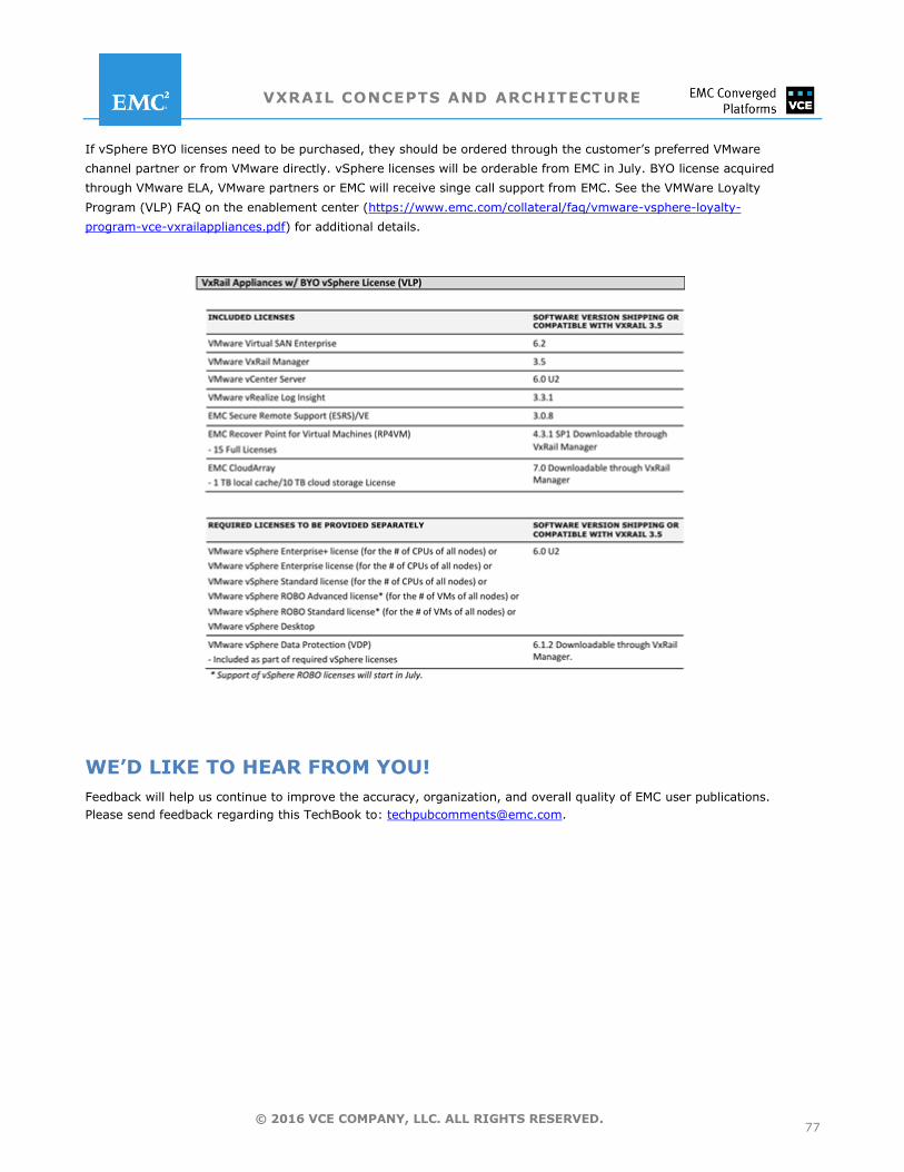
VXRAIL CONCEPTS AND ARCHITECTURE
77 © 2016 VCE COMPANY, LLC. ALL RIGHTS RESERVED.
If vSphere BYO licenses need to be purchased, they should be ordered through the customer’s preferred VMware
channel partner or from VMware directly. vSphere licenses will be orderable from EMC in July. BYO license acquired
through VMware ELA, VMware partners or EMC will receive singe call support from EMC. See the VMWare Loyalty
Program (VLP) FAQ on the enablement center (https://www.emc.com/collateral/faq/vmware-vsphere-loyalty-
program-vce-vxrailappliances.pdf) for additional details.
WE’D LIKE TO HEAR FROM YOU!
Feedback will help us continue to improve the accuracy, organization, and overall quality of EMC user publications.
Please send feedback regarding this TechBook to: [email protected].
VXRAIL CONCEPTS AND ARCHITECTURE
78 © 2016 VCE COMPANY, LLC. ALL RIGHTS RESERVED.
ABOUT VCE VCE, an EMC Federation Company, is the world market leader in converged infrastructure and converged solutions. VCE
accelerates the adoption of converged infrastructure and cloud-based computing models that reduce IT costs while improving
time to market. VCE delivers the industry's only fully integrated and virtualized cloud infrastructure systems, allowing customers
to focus on business innovation instead of integrating, validating, and managing IT infrastructure. VCE solutions are available
through an extensive partner network, and cover horizontal applications, vertical industry offerings, and application development
environments, allowing customers to focus on business innovation instead of integrating, validating, and managing IT
infrastructure.
For more information, go to vce.com.
Copyright © 2010-2016 VCE Company, LLC. All rights reserved. VCE, VCE Vision, VCE Vscale, Vblock, VxBlock, VxRack, VxRail, and the VCE logo are registered trademarks or trademarks of VCE Company LLC. All other trademarks used herein are the property of their respective owners.