vd tinhtoan cautreo
TRANSCRIPT
Advanced Application 3
Completed State and Construction Stage Analyses of a Suspension Bridge
CCCiiivvviiilll
ADVANCED APPLICATIONS
2
CONTENTS
Introduction 1 Procedure for Completed State Analysis 2 Bridge Dimensions 3
Completed State Analysis Modeling 4 Structural Modeling 4 Assign Working Environment 5 Define Material Properties 6 Define Section Properties 7 Initial Equilibrium State Analysis 9 Divide pylon elements to create pylon transverse beams 13 Input Boundary Conditions 17 Define Structure Groups 23 Input loadings 25 Suspension Bridge Analysis Control 27 Remove Nonlinear Analysis Control Data and Suspension Bridge Analysis Data 30 Remove and Modify Beam End Release Conditions for Deck 32 Input Load Cases and Static Loads 35
Perform Structural Analysis (Completed State Analysis) 37
Review Results of Completed State Analysis 38 Static Analysis Results 38
Modeling for Construction Stage Analysis 45 Assign Working Environment 46 Define Construction Stage Names 47 Assign Structure Groups 48 Assign Boundary Groups 56 Define Construction Stage Loads and Load Groups 61 Define Construction Stages 62 Input Construction Stage Analysis Data 69
Perform Structural Analysis (Construction Stage Analysis) 69
Review Construction Stage Analysis Results 70 Review Deformed Shape 70 Review moments 74 Review axial forces 75 Review deformed shape using animation 77
Completed State and Construction Stage Analyses of a Suspension Bridge
1
Introduction Suspension bridges can generally be classified as long span structures.
Suspension bridges comprise longitudinal deck (main girders) supported
by hangers suspended from cables. The cables are connected to anchors
at each end.
The analysis of a suspension bridge is divided into completed state
analysis and construction stage analysis.
The completed state analysis is performed to check the behavior of the
completed bridge. At this stage, the structure is in balance under self-
weight, and the deflection due to the self-weight has already occurred.
This stage is referred to as the initial equilibrium state of the suspension
bridge. The initial equilibrium state analysis will provide the coordinates
and tension forces in the cables. The completed state analysis of the
suspension bridge is performed to check the behavior of the structure
under additional loads such as live, seismic and wind loadings. The self
weight loading in the initial equilibrium state will also be added to the total
loading for the completed state analysis.
Suspension bridges exhibit significant nonlinear behavior during the
construction stages. But it can be assumed that the bridge behaves
linearly for additional loads (vehicle, wind load, etc.) in the completed state
analysis. This is due to the fact that sufficient tension forces are induced
into the main cables and hangers under the initial equilibrium state loading.
It is thus possible to perform a linearized analysis for the additional static
loads at the completed state by converting the tension forces in the main
cables and hangers resulting from the initial equilibrium state loading into
increased geometric stiffness of those components. This linearized
analytical procedure to convert section forces to geometric stiffness is
referred to as the linearized finite displacement method. This
procedure is adopted because a solution can be found with relative ease
within acceptable error limits in the completed state analysis.
Construction stage analysis is performed to check the structural stability
and to calculate section forces during erection. In carrying out the
construction stage analysis, large displacement theory (geometric
nonlinear theory) is applied in which equilibrium equations are formulated
to represent the deformed shape. The effect of large displacements
cannot be ignored during the construction stage analysis. The
construction stage analysis is performed in a backward sequence from the
ADVANCED APPLICATIONS
2
state of equilibrium as defined by the initial equilibrium state analysis.
This tutorial explains the overall modeling and result analyzing capabilities
for the completed state and construction stage analyses of a suspension
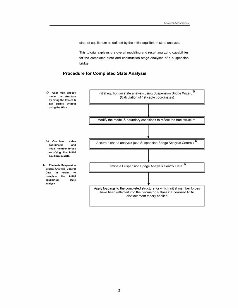
bridge. Procedure for Completed State Analysis
Initial equilibrium state analysis using Suspension Bridge Wizard(Calculation of 1st cable coordinates)
User may directly model the structure by fixing the towers & sag points without using the Wizard.
Modify the model & boundary conditions to reflect the true structure.
Accurate shape analysis (use Suspension Bridge Analysis Control) Calculate cable coordinates and initial member forces satisfying the initial equilibrium state.
Eliminate Suspension Bridge Analysis Control Data
Eliminate Suspension Bridge Analysis Control Data in order to complete the initial equilibrium state analysis.
Apply loadings to the completed structure for which initial member forces have been reflected into the geometric stiffness: Linearized finite
displacement theory applied
Completed State and Construction Stage Analyses of a Suspension Bridge
3
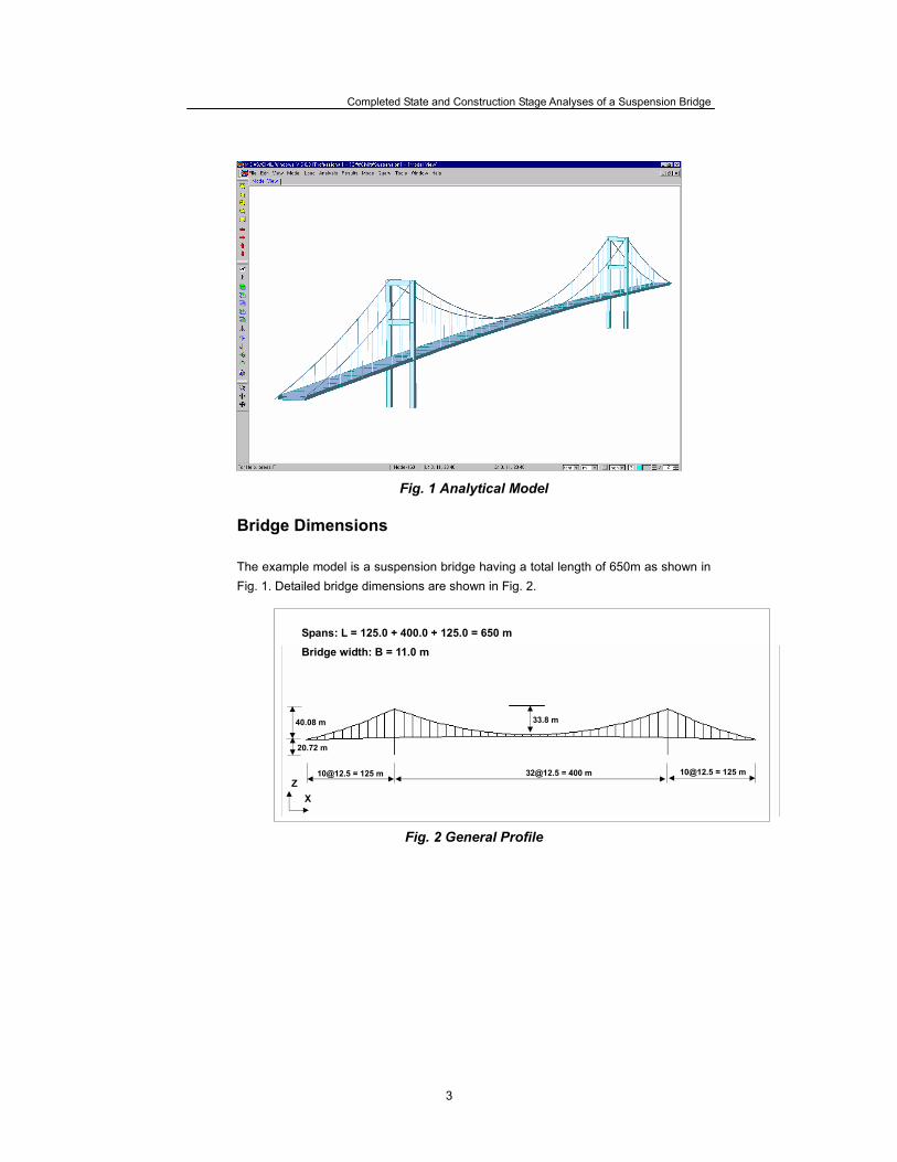
Fig. 1 Analytical Model
Bridge Dimensions
The example model is a suspension bridge having a total length of 650m as shown in Fig. 1. Detailed bridge dimensions are shown in Fig. 2.
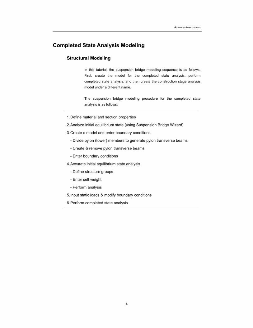
Fig. 2 General Profile
[email protected] = 125 m [email protected] = 400 m [email protected] = 125 m
40.08 m 33.8 m
Spans: L = 125.0 + 400.0 + 125.0 = 650 m
Bridge width: B = 11.0 m
20.72 m
X Z
ADVANCED APPLICATIONS
4
Completed State Analysis Modeling
Structural Modeling
In this tutorial, the suspension bridge modeling sequence is as follows.
First, create the model for the completed state analysis, perform
completed state analysis, and then create the construction stage analysis
model under a different name.
The suspension bridge modeling procedure for the completed state
analysis is as follows:
1. Define material and section properties
2. Analyze initial equilibrium state (using Suspension Bridge Wizard)
3. Create a model and enter boundary conditions
- Divide pylon (tower) members to generate pylon transverse beams
- Create & remove pylon transverse beams
- Enter boundary conditions
4. Accurate initial equilibrium state analysis
- Define structure groups
- Enter self weight
- Perform analysis
5. Input static loads & modify boundary conditions
6. Perform completed state analysis
Completed State and Construction Stage Analyses of a Suspension Bridge
5
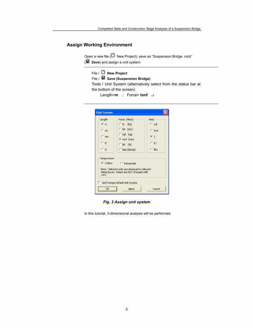
Assign Working Environment Open a new file ( New Project), save as “Suspension Bridge .mcb”
( Save) and assign a unit system.
File / New Project File / Save (Suspension Bridge) Tools / Unit System (alternatively select from the status bar at the bottom of the screen)
Length>m ; Force> tonf ↵
Fig. 3 Assign unit system
In this tutorial, 3-dimensional analysis will be performed.
ADVANCED APPLICATIONS
6
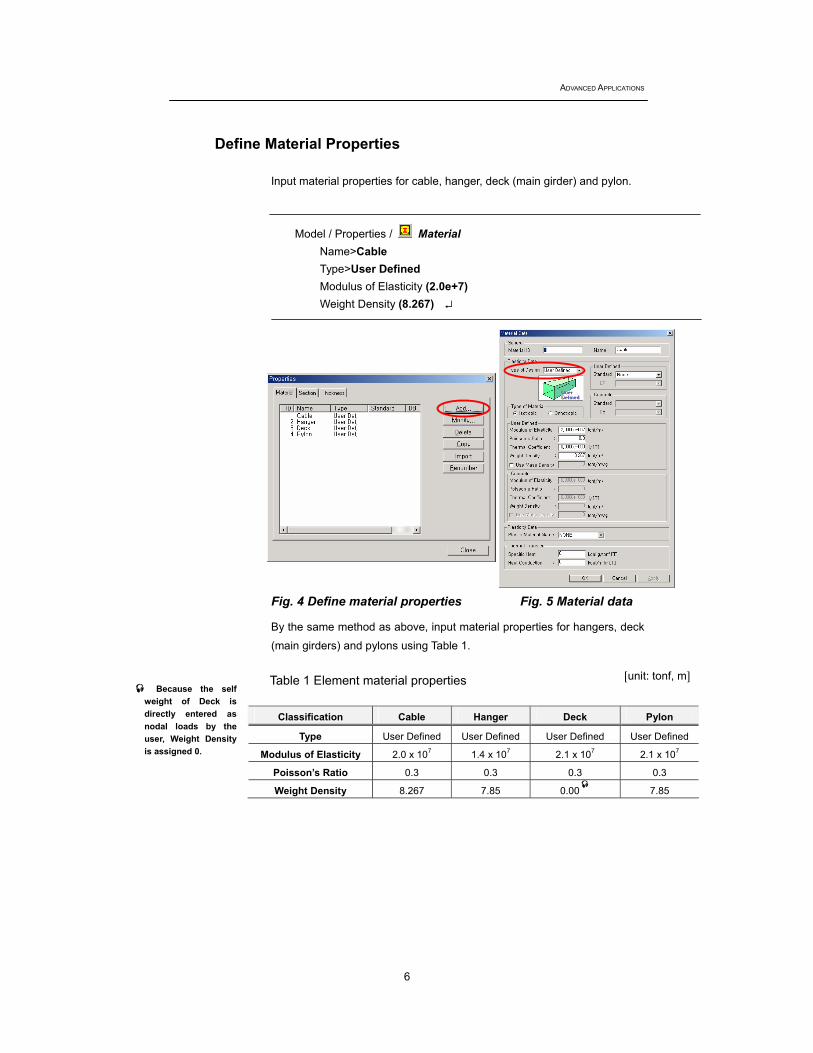
Define Material Properties
Input material properties for cable, hanger, deck (main girder) and pylon.
Model / Properties / Material Name>Cable Type>User Defined Modulus of Elasticity (2.0e+7) Weight Density (8.267) ↵
Fig. 4 Define material properties Fig. 5 Material data
By the same method as above, input material properties for hangers, deck
(main girders) and pylons using Table 1. Table 1 Element material properties
Classification Cable Hanger Deck Pylon
Type User Defined User Defined User Defined User Defined
Modulus of Elasticity 2.0 x 10⁷ 1.4 x 10⁷ 2.1 x 10⁷ 2.1 x 10⁷
Poisson’s Ratio 0.3 0.3 0.3 0.3
Weight Density 8.267 7.85 0.00 7.85
[unit: tonf, m] Because the self weight of Deck is directly entered as nodal loads by the user, Weight Density is assigned 0.
Completed State and Construction Stage Analyses of a Suspension Bridge
7
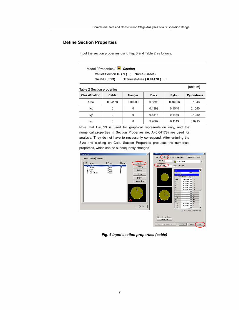
Define Section Properties Input the section properties using Fig. 6 and Table 2 as follows:
Model / Properties / Section
Value>Section ID ( 1 ) ; Name (Cable) Size>D (0.23) ; Stiffness>Area ( 0.04178 ) ↵
Table 2 Section properties
Classification Cable Hanger Deck Pylon Pylon-trans
Area 0.04178 0.00209 0.5395 0.16906 0.1046
Ixx 0 0 0.4399 0.1540 0.1540
Iyy 0 0 0.1316 0.1450 0.1080
Izz 0 0 3.2667 0.1143 0.0913
Note that D=0.23 is used for graphical representation only, and the numerical properties in Section Properties (ie, A=0.04178) are used for analysis. They do not have to necessarily correspond. After entering the Size and clicking on Calc. Section Properties produces the numerical properties, which can be subsequently changed.
Fig. 6 Input section properties (cable)
[unit: m]
ADVANCED APPLICATIONS
8
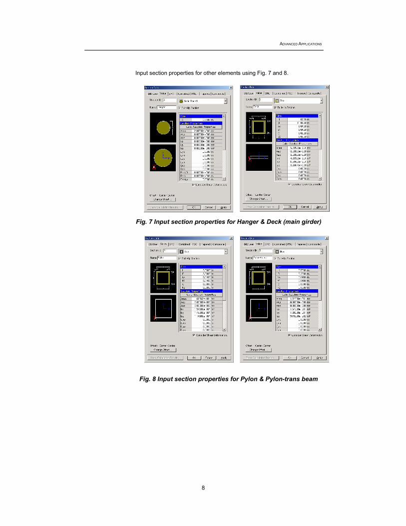
Input section properties for other elements using Fig. 7 and 8.
Fig. 7 Input section properties for Hanger & Deck (main girder)
Fig. 8 Input section properties for Pylon & Pylon-trans beam
Completed State and Construction Stage Analyses of a Suspension Bridge
9
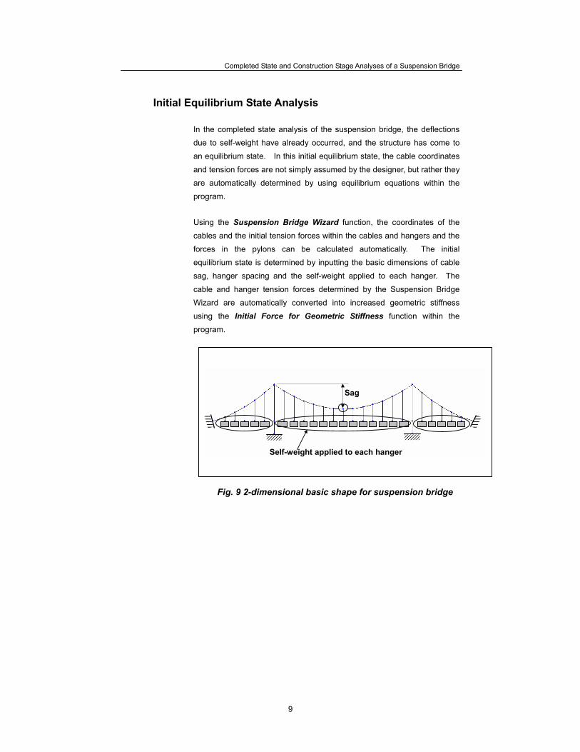
Initial Equilibrium State Analysis In the completed state analysis of the suspension bridge, the deflections
due to self-weight have already occurred, and the structure has come to
an equilibrium state. In this initial equilibrium state, the cable coordinates
and tension forces are not simply assumed by the designer, but rather they
are automatically determined by using equilibrium equations within the
program. Using the Suspension Bridge Wizard function, the coordinates of the
cables and the initial tension forces within the cables and hangers and the
forces in the pylons can be calculated automatically. The initial
equilibrium state is determined by inputting the basic dimensions of cable
sag, hanger spacing and the self-weight applied to each hanger. The
cable and hanger tension forces determined by the Suspension Bridge
Wizard are automatically converted into increased geometric stiffness
using the Initial Force for Geometric Stiffness function within the
program.
Fig. 9 2-dimensional basic shape for suspension bridge
Self-weight applied to each hanger
Sag
ADVANCED APPLICATIONS
10
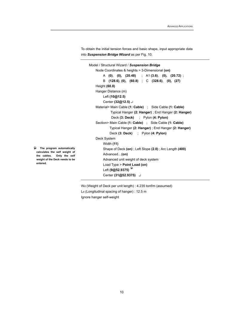
To obtain the initial tension forces and basic shape, input appropriate data
into Suspension Bridge Wizard as per Fig. 10.
Model / Structural Wizard / Suspension Bridge Node Coordinates & heights > 3-Dimensional (on)
A (0), (0), (20.48) ; A1 (3.6), (0), (20.72) ; B (128.6), (0), (60.8) ; C (328.6), (0), (27)
Height (60.8) Hanger Distance (m)
Left ([email protected]) Center ([email protected]) ↵
Material> Main Cable (1: Cable) ; Side Cable (1: Cable) Typical Hanger (2: Hanger) ; End Hanger (2: Hanger) Deck (3: Deck) ; Pylon (4: Pylon)
Section> Main Cable (1: Cable) ; Side Cable (1: Cable) Typical Hanger (2: Hanger) ; End Hanger (2: Hanger) Deck (3: Deck) ; Pylon (4: Pylon)
Deck System Width (11) Shape of Deck (on) ; Left Slope (2.0) ; Arc Length (400) Advanced…(on) Advanced unit weight of deck system Load Type > Point Load (on) Left ([email protected]) Center ([email protected]) ↵
Wd (Weight of Deck per unit length) : 4.235 tonf/m (assumed)
Ld (Longitudinal spacing of hanger) : 12.5 m
Ignore hanger self-weight
The program automatically calculates the self weight of the cables. Only the self weight of the Deck needs to be entered.

Completed State and Construction Stage Analyses of a Suspension Bridge
11
As explained earlier, the geometric shape of the suspension bridge,
especially the cable coordinates cannot be arbitrarily determined by the
designer. Rather they will be determined by the catenary equation
satisfying the equilibrium condition within the program. Using the
Suspension Bridge Wizard function, the geometric shape and initial
tension forces can be calculated. As shown in Fig. 10, all coordinates of
the suspension bridge, including the coordinates of the cables can be
determined automatically by entering the coordinates of the pylons, sag
(B-C), slope of deck, hanger spacing and self weight applied to the
hangers.
Fig. 10 Suspension Bridge Wizard Input Window
ADVANCED APPLICATIONS
12
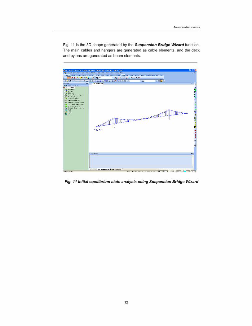
Fig. 11 is the 3D shape generated by the Suspension Bridge Wizard function. The main cables and hangers are generated as cable elements, and the deck and pylons are generated as beam elements.
Fig. 11 Initial equilibrium state analysis using Suspension Bridge Wizard
Completed State and Construction Stage Analyses of a Suspension Bridge
13
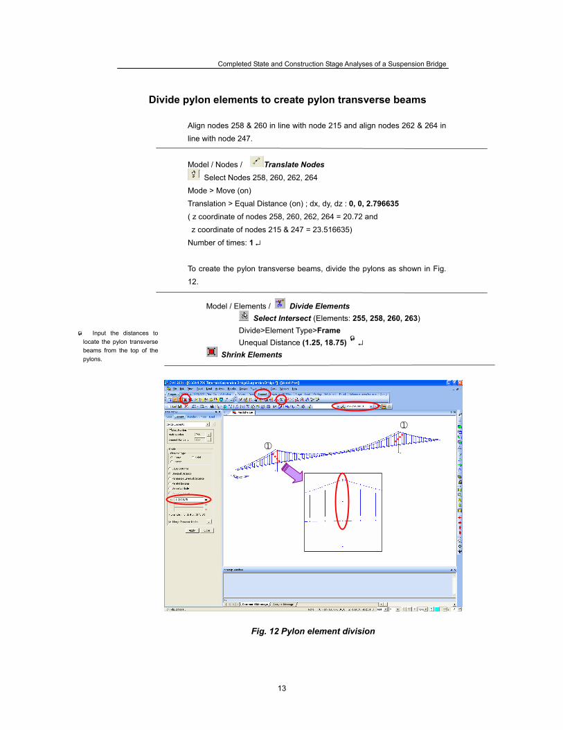
Divide pylon elements to create pylon transverse beams
Align nodes 258 & 260 in line with node 215 and align nodes 262 & 264 in
line with node 247.
Model / Nodes / Translate Nodes
Select Nodes 258, 260, 262, 264
Mode > Move (on)
Translation > Equal Distance (on) ; dx, dy, dz : 0, 0, 2.796635
( z coordinate of nodes 258, 260, 262, 264 = 20.72 and
z coordinate of nodes 215 & 247 = 23.516635)
Number of times: 1 ↵
To create the pylon transverse beams, divide the pylons as shown in Fig.
12.
Model / Elements / Divide Elements Select Intersect (Elements: 255, 258, 260, 263)
Divide>Element Type>Frame Unequal Distance (1.25, 18.75) ↵
Shrink Elements
Fig. 12 Pylon element division
Input the distances to locate the pylon transverse beams from the top of the pylons.
①
①

ADVANCED APPLICATIONS
14
Create pylon transverse beams Generate the pylon transverse beams as follows:
Zoom Window (Magnify the left pylon as Fig. 13) Model / Elements / Create Elements
Element Type>General beam/Tabered beam Material>4: Pylon ; Section>5: Pylon-trans Intersect>Node (on) ; Elem (on) Nodal Connectivity (260, 258) ; (269, 267) ; (268,266) ↵
Fig. 13 Generate pylon transverse beams (left pylon)
268
266
267
269
260
258
Completed State and Construction Stage Analyses of a Suspension Bridge
15
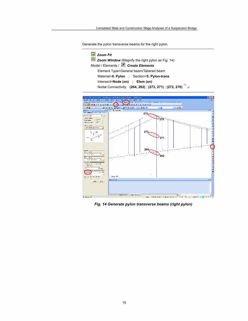
Generate the pylon transverse beams for the right pylon.
Zoom Fit Zoom Window (Magnify the right pylon as Fig. 14)
Model / Elements / Create Elements Element Type>General beam/Tabered beam Material>4: Pylon ; Section>5: Pylon-trans Intersect>Node (on) ; Elem (on) Nodal Connectivity (264, 262) ; (273, 271) ; (272, 270) ↵
Fig. 14 Generate pylon transverse beams (right pylon)
272
270
271
273
262
264
ADVANCED APPLICATIONS
16
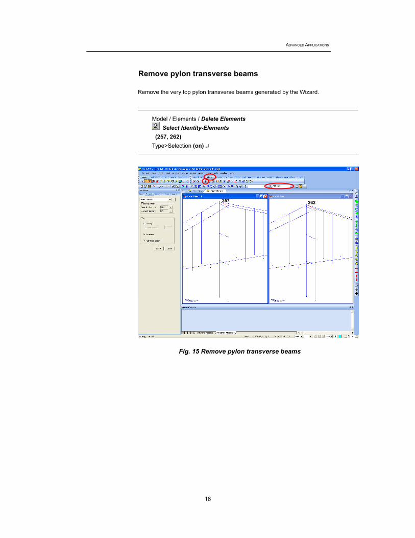
Remove pylon transverse beams
Remove the very top pylon transverse beams generated by the Wizard.
Model / Elements / Delete Elements Select Identity-Elements
(257, 262) Type>Selection (on) ↵
Fig. 15 Remove pylon transverse beams
257 262
Completed State and Construction Stage Analyses of a Suspension Bridge
17
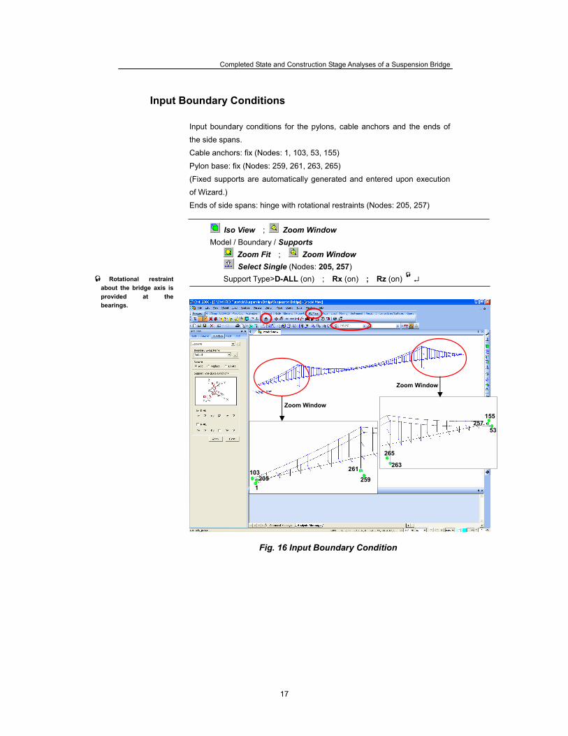
Input Boundary Conditions Input boundary conditions for the pylons, cable anchors and the ends of
the side spans.
Cable anchors: fix (Nodes: 1, 103, 53, 155)
Pylon base: fix (Nodes: 259, 261, 263, 265)
(Fixed supports are automatically generated and entered upon execution
of Wizard.)
Ends of side spans: hinge with rotational restraints (Nodes: 205, 257)
Iso View ; Zoom Window Model / Boundary / Supports
Zoom Fit ; Zoom Window Select Single (Nodes: 205, 257)
Support Type>D-ALL (on) ; Rx (on) ; Rz (on) ↵
Fig. 16 Input Boundary Condition
Rotational restraint about the bridge axis is provided at the bearings.
Zoom Window
Zoom Window
103205
1
261
259
155257
53
265
263
ADVANCED APPLICATIONS
18
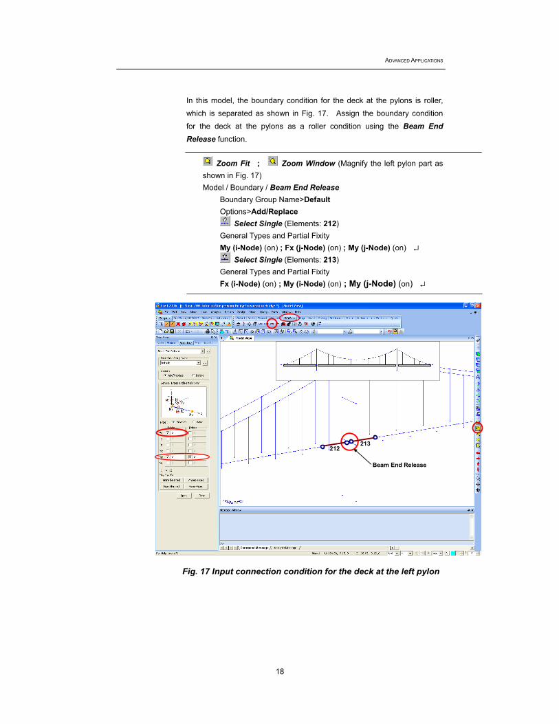
In this model, the boundary condition for the deck at the pylons is roller,
which is separated as shown in Fig. 17. Assign the boundary condition
for the deck at the pylons as a roller condition using the Beam End Release function.
Zoom Fit ; Zoom Window (Magnify the left pylon part as
shown in Fig. 17) Model / Boundary / Beam End Release
Boundary Group Name>Default Options>Add/Replace
Select Single (Elements: 212) General Types and Partial Fixity My (i-Node) (on) ; Fx (j-Node) (on) ; My (j-Node) (on) ↵
Select Single (Elements: 213) General Types and Partial Fixity Fx (i-Node) (on) ; My (i-Node) (on) ; My (j-Node) (on) ↵
Fig. 17 Input connection condition for the deck at the left pylon
212
Beam End Release
213
Completed State and Construction Stage Analyses of a Suspension Bridge
19
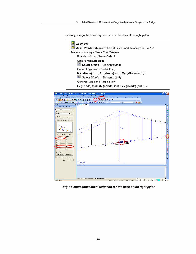
Similarly, assign the boundary condition for the deck at the right pylon.
Zoom Fit Zoom Window (Magnify the right pylon part as shown in Fig. 18)
Model / Boundary / Beam End Release Boundary Group Name>Default Options>Add/Replace
Select Single (Elements: 244) General Types and Partial Fixity My (i-Node) (on) ; Fx (j-Node) (on) ; My (j-Node) (on) ; ↵
Select Single (Elements: 245) General Types and Partial Fixity Fx (i-Node) (on); My (i-Node) (on) ; My (j-Node) (on) ; ↵
Fig. 18 Input connection condition for the deck at the right pylon
245244
ADVANCED APPLICATIONS
20
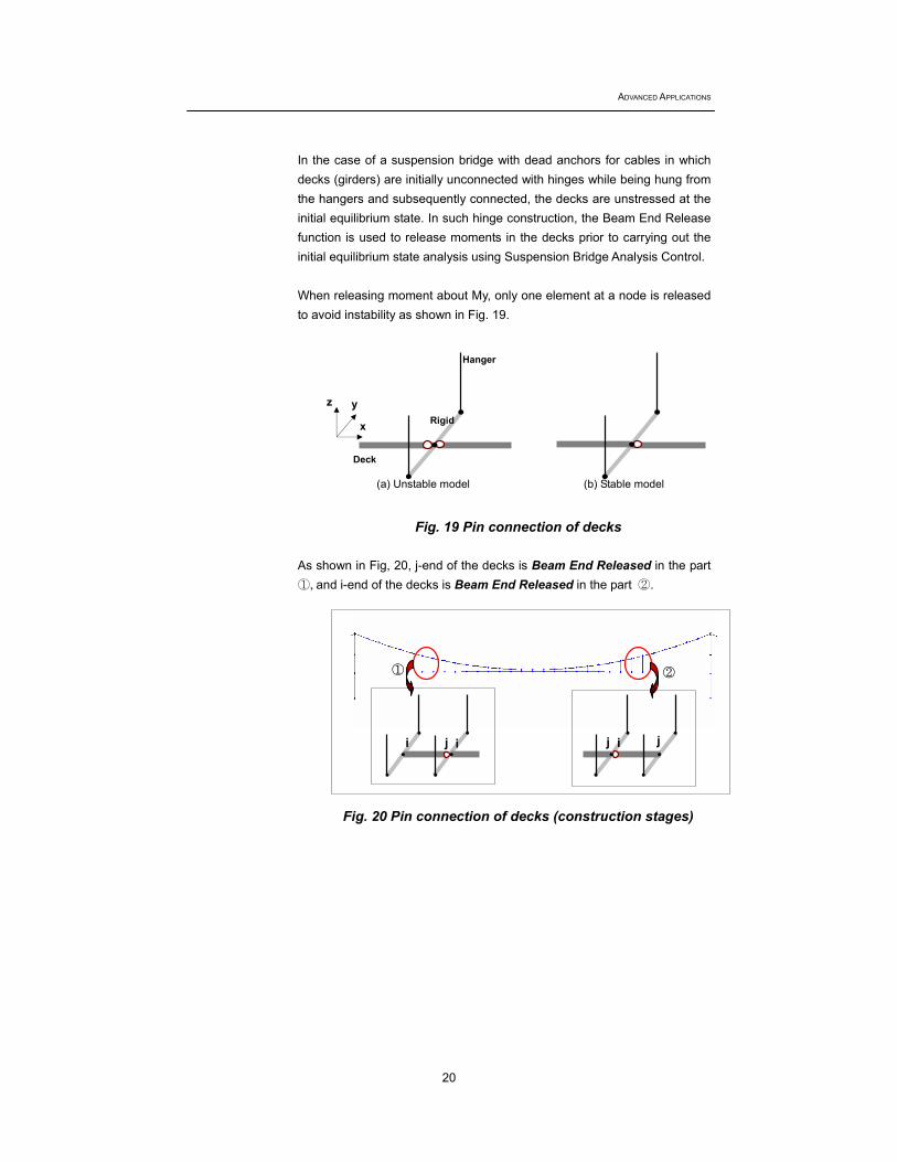
In the case of a suspension bridge with dead anchors for cables in which decks (girders) are initially unconnected with hinges while being hung from the hangers and subsequently connected, the decks are unstressed at the initial equilibrium state. In such hinge construction, the Beam End Release function is used to release moments in the decks prior to carrying out the initial equilibrium state analysis using Suspension Bridge Analysis Control. When releasing moment about My, only one element at a node is released to avoid instability as shown in Fig. 19.
Fig. 19 Pin connection of decks
As shown in Fig, 20, j-end of the decks is Beam End Released in the part ①, and i-end of the decks is Beam End Released in the part ②.
Fig. 20 Pin connection of decks (construction stages)
(b) Stable model
① ②
i j i j i j
(a) Unstable model
Deck
Hanger
Rigid z
x
y
Completed State and Construction Stage Analyses of a Suspension Bridge
21
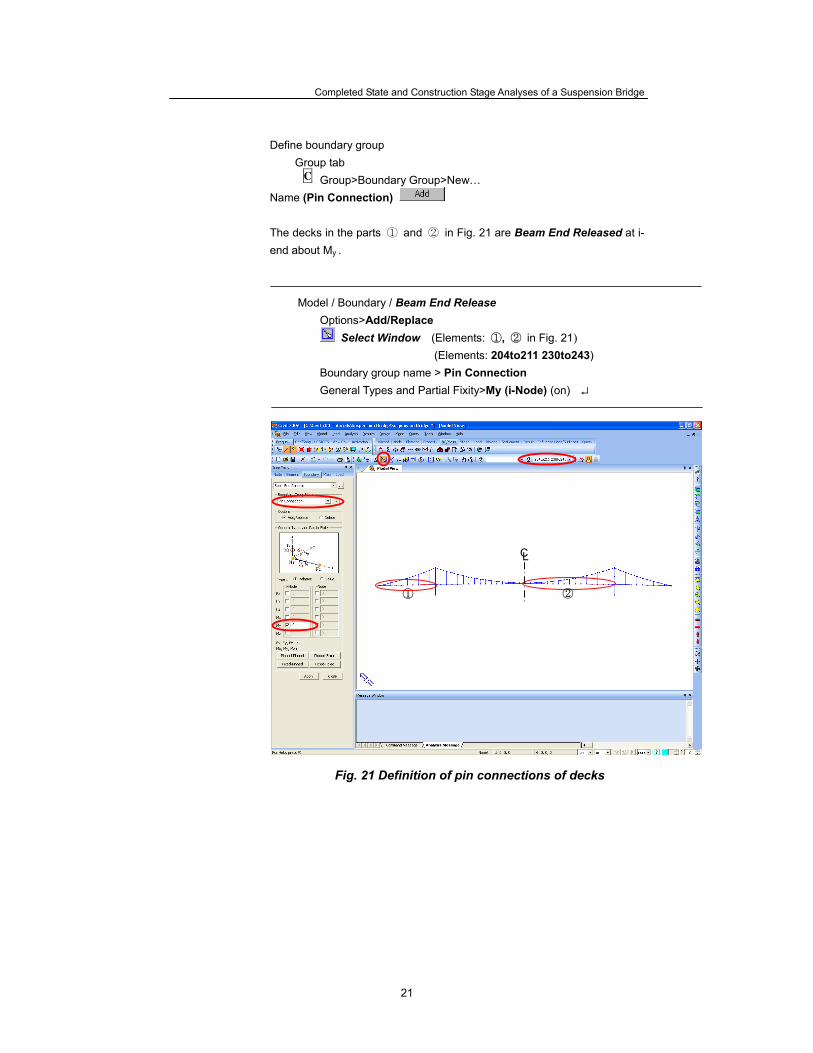
Define boundary group Group tab
Group>Boundary Group>New… Name (Pin Connection)
The decks in the parts ① and ② in Fig. 21 are Beam End Released at i-end about My .
Model / Boundary / Beam End Release Options>Add/Replace
Select Window (Elements: ①, ② in Fig. 21)
(Elements: 204to211 230to243) Boundary group name > Pin Connection General Types and Partial Fixity>My (i-Node) (on) ↵
Fig. 21 Definition of pin connections of decks
C
①
CL
②
ADVANCED APPLICATIONS
22
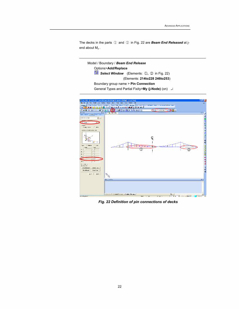
The decks in the parts ① and ② in Fig. 22 are Beam End Released at j-end about My .
Model / Boundary / Beam End Release Options>Add/Replace
Select Window (Elements: ①, ② in Fig. 22)
(Elements: 214to228 246to253) Boundary group name > Pin Connection General Types and Partial Fixity>My (j-Node) (on) ↵
Fig. 22 Definition of pin connections of decks
② ①
CL
Completed State and Construction Stage Analyses of a Suspension Bridge
23
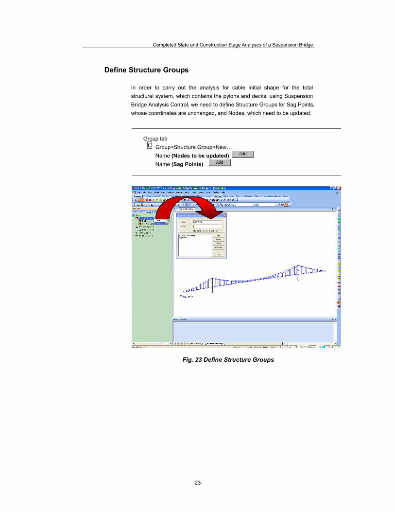
Define Structure Groups In order to carry out the analysis for cable initial shape for the total structural system, which contains the pylons and decks, using Suspension Bridge Analysis Control, we need to define Structure Groups for Sag Points, whose coordinates are unchanged, and Nodes, which need to be updated.
Group tab
Group>Structure Group>New… Name (Nodes to be updated) Name (Sag Points)
Fig. 23 Define Structure Groups
C
ADVANCED APPLICATIONS
24
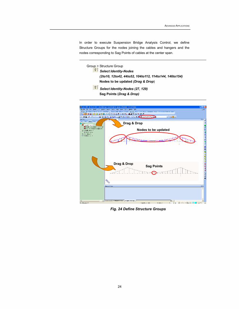
In order to execute Suspension Bridge Analysis Control, we define Structure Groups for the nodes joining the cables and hangers and the nodes corresponding to Sag Points of cables at the center span.
Group > Structure Group
Select Identity-Nodes (2to10, 12to42, 44to52, 104to112, 114to144, 146to154) Nodes to be updated (Drag & Drop)
Select Identity-Nodes (27, 129) Sag Points (Drag & Drop)
Fig. 24 Define Structure Groups
Drag & Drop
Nodes to be updated
Sag Points Drag & Drop

Completed State and Construction Stage Analyses of a Suspension Bridge
25
Input loadings The Static Load Case, Self Weight, is automatically generated and entered upon execution of Wizard. Define a Load Group for Self Weight and modify the Load Group of Self Weight already created.
Load / Self Weight
Load Case Name > Self Weight (Select) Load Group Name > ↵ Define Load Group > Name > L_G ; ↵
↵ Load Group Name > L_G Self weight factor > Z = -1
↵
Fig 25. Entry of self weight excluding the decks
ADVANCED APPLICATIONS
26
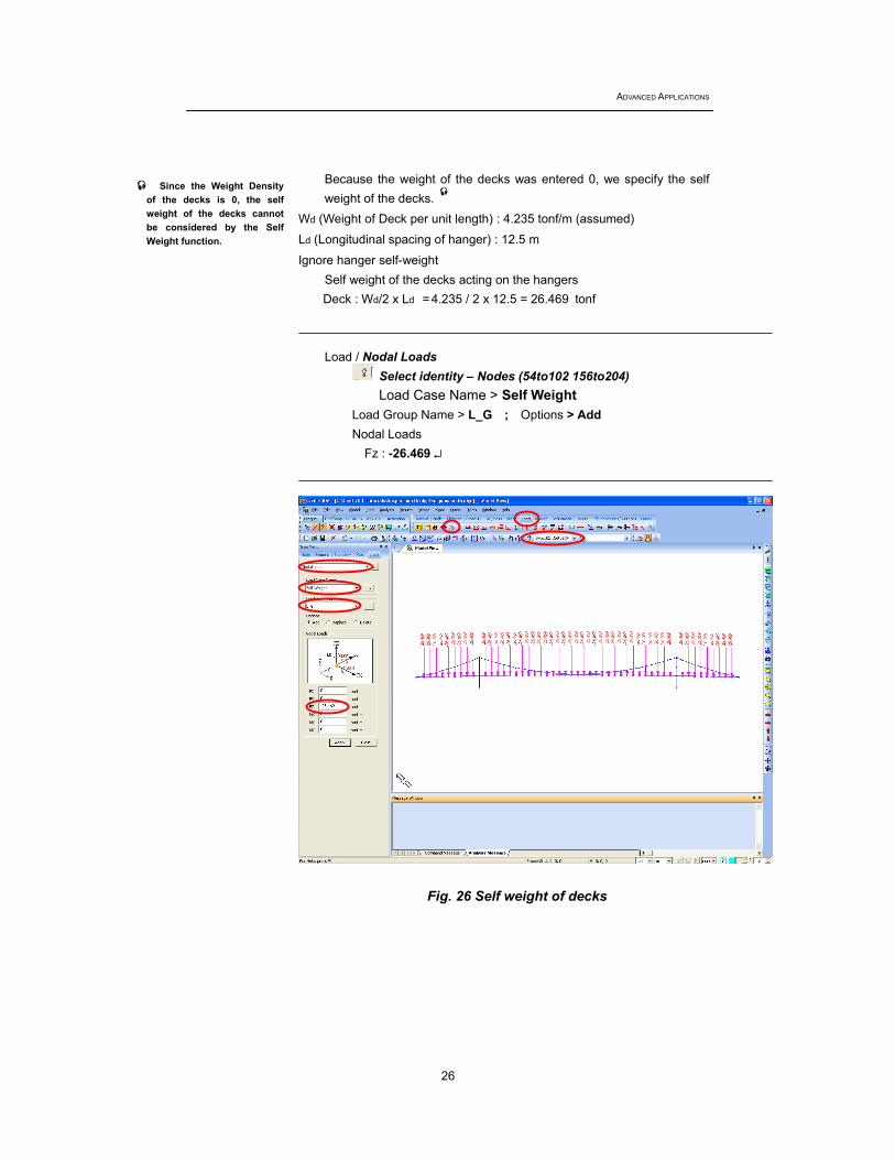
Because the weight of the decks was entered 0, we specify the self weight of the decks.
Wd (Weight of Deck per unit length) : 4.235 tonf/m (assumed)
Ld (Longitudinal spacing of hanger) : 12.5 m
Ignore hanger self-weight Self weight of the decks acting on the hangers Deck : Wd/2 x Ld = 4.235 / 2 x 12.5 = 26.469 tonf
Load / Nodal Loads
Select identity – Nodes (54to102 156to204) Load Case Name > Self Weight
Load Group Name > L_G ; Options > Add Nodal Loads
Fz : -26.469 ↵
Fig. 26 Self weight of decks
Since the Weight Density of the decks is 0, the self weight of the decks cannot be considered by the Self Weight function.

Completed State and Construction Stage Analyses of a Suspension Bridge
27
Suspension Bridge Analysis Control
Suspension Bridge Analysis Control executes accurate initial equilibrium state analysis for the total structural system, which reflects modified pylons and decks, based on the cable coordinates generated from Suspension Bridge Wizard, unstressed length and horizontal tensions.
Analysis / Suspension Bridge Analysis Control Control Parameters> Number of Iterations ; (10) Node Group to be Updated ; (Nodes to be updated) Convergence Tolerance ; (1e-005) Sag Point Group ; (Sag Points) Constant Horizontal Force of Cable>(off) Load Case to be Considered; (Self Weight) Scale Factor; 1 ↵
↵ Analysis / Perform Analysis
Fig. 27 Suspension Bridge Analysis Control
Accurate initial equilibrium state analysis is performed for the self weight of the bridge.
ADVANCED APPLICATIONS
28
Upon execution of Suspension Bridge Analysis Control, Initial Forces (Large Displacement) are calculated, which are used to represent the initial equilibrium state in large displacement analysis and construction stage large displacement analysis. Initial Forces (Large Displacement) includes Initial Forces for Geometric Stiffness and Equilibrium Element Nodal Force. Initial Forces (Small Displacement) are calculated, which are used to represent initial equilibrium state in linear analysis. Initial Forces (Small Displacement) includes Initial Element Forces. The calculated values can be checked in tables.
Load / Load Tables / Initial Forces for Geometric Stiffness ↵ Load / Initial Forces / Large Displacement / Equilibrium Element Nodal Force ↵ Load / Initial Forces/ Small Displacement/ Initial Element Forces ↵
Initial Forces (Large Displacement)
Initial Forces for Geometric Stiffness This is used to represent initial equilibrium state in construction stage large displacement analysis and large displacement analysis. The program internally generates external forces, which are in equilibrium with the entered member forces as well as the initial forces. Once the initial forces are considered for formulating geometric stiffness, the data is ignored in linear analyses such as completed state analysis. Equilibrium Element Nodal Force (used in construction stage analysis) Equilibrium Element Nodal Forces are used specifically for backward construction stage large displacement analysis. Without loads, which are in equilibrium with these nodal forces, the nodal forces cause deformation. The nodal forces are ignored in large displacement analysis having no construction stages.
The values of Initial Forces calculated by Suspension Bridge Analysis Control can be readily checked in tables by right-clicking in Works Tree.
Completed State and Construction Stage Analyses of a Suspension Bridge
29
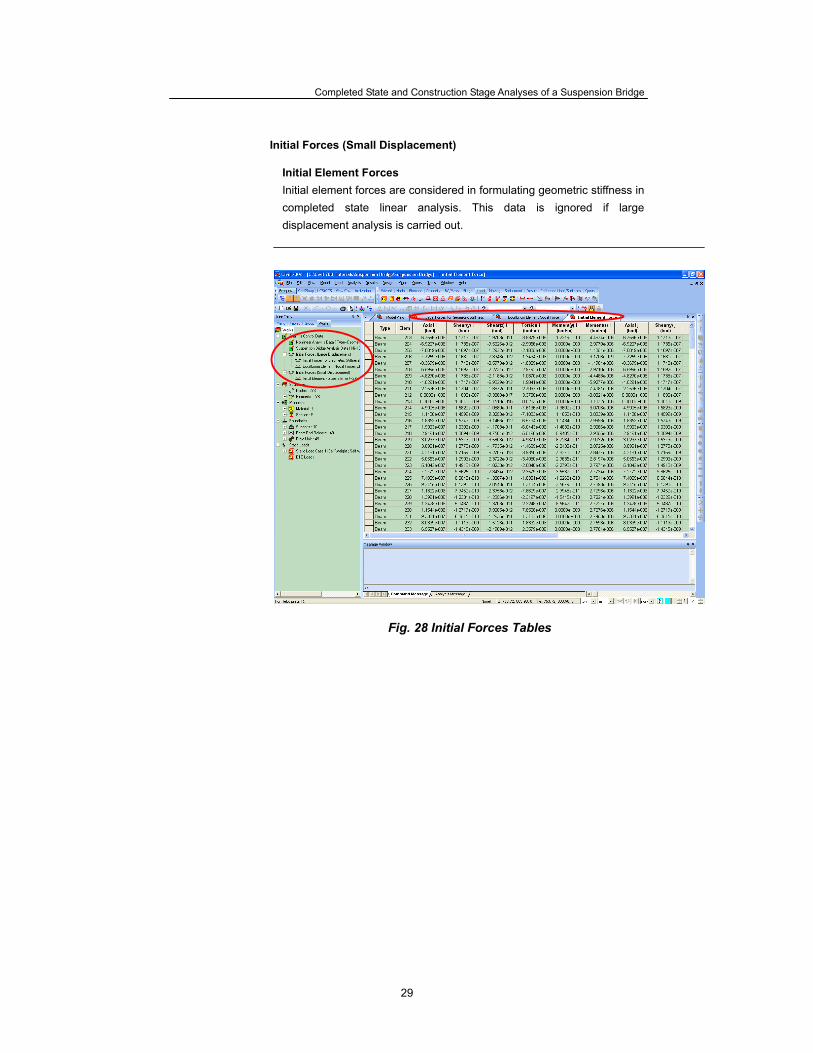
Initial Forces (Small Displacement) Initial Element Forces Initial element forces are considered in formulating geometric stiffness in completed state linear analysis. This data is ignored if large displacement analysis is carried out.
Fig. 28 Initial Forces Tables
ADVANCED APPLICATIONS
30
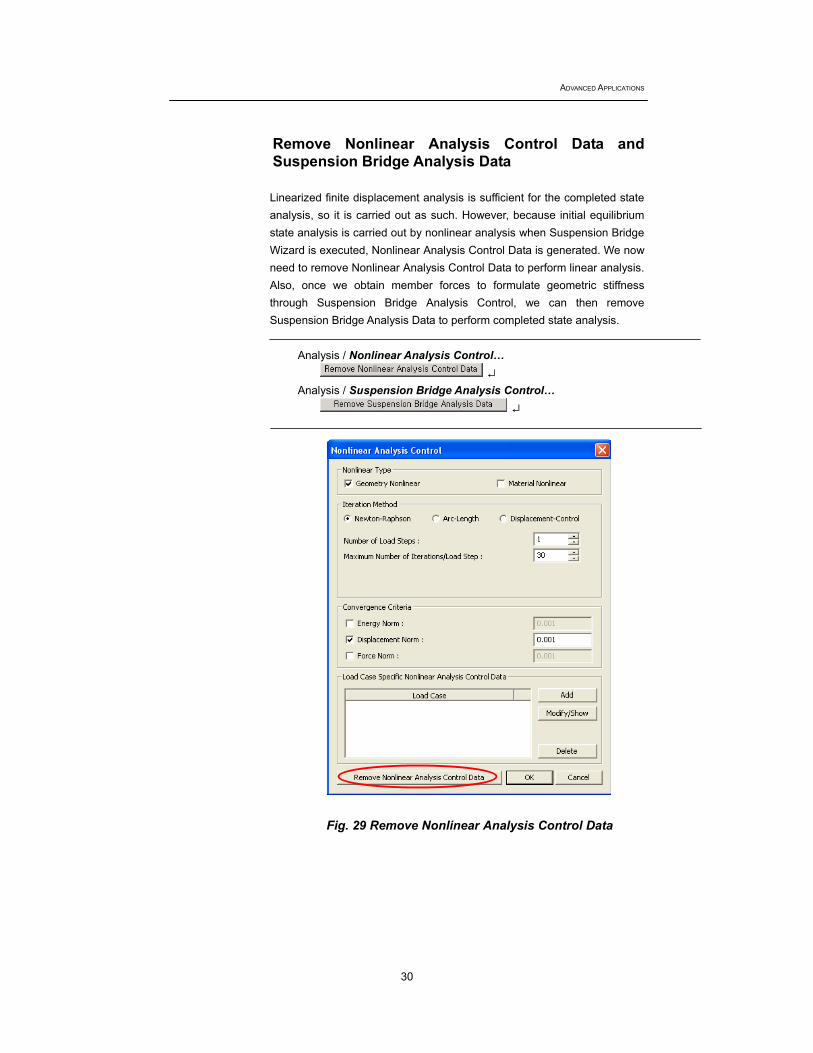
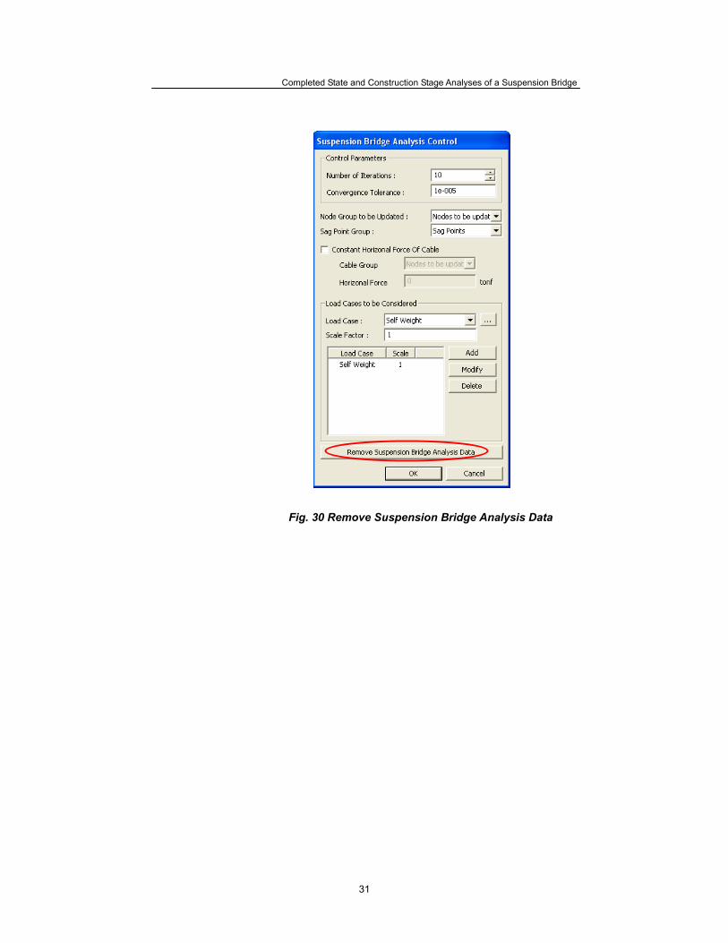
Remove Nonlinear Analysis Control Data and Suspension Bridge Analysis Data Linearized finite displacement analysis is sufficient for the completed state analysis, so it is carried out as such. However, because initial equilibrium state analysis is carried out by nonlinear analysis when Suspension Bridge Wizard is executed, Nonlinear Analysis Control Data is generated. We now need to remove Nonlinear Analysis Control Data to perform linear analysis. Also, once we obtain member forces to formulate geometric stiffness through Suspension Bridge Analysis Control, we can then remove Suspension Bridge Analysis Data to perform completed state analysis.
Analysis / Nonlinear Analysis Control… ↵
Analysis / Suspension Bridge Analysis Control… ↵
Fig. 29 Remove Nonlinear Analysis Control Data
Completed State and Construction Stage Analyses of a Suspension Bridge
31
Fig. 30 Remove Suspension Bridge Analysis Data
ADVANCED APPLICATIONS
32
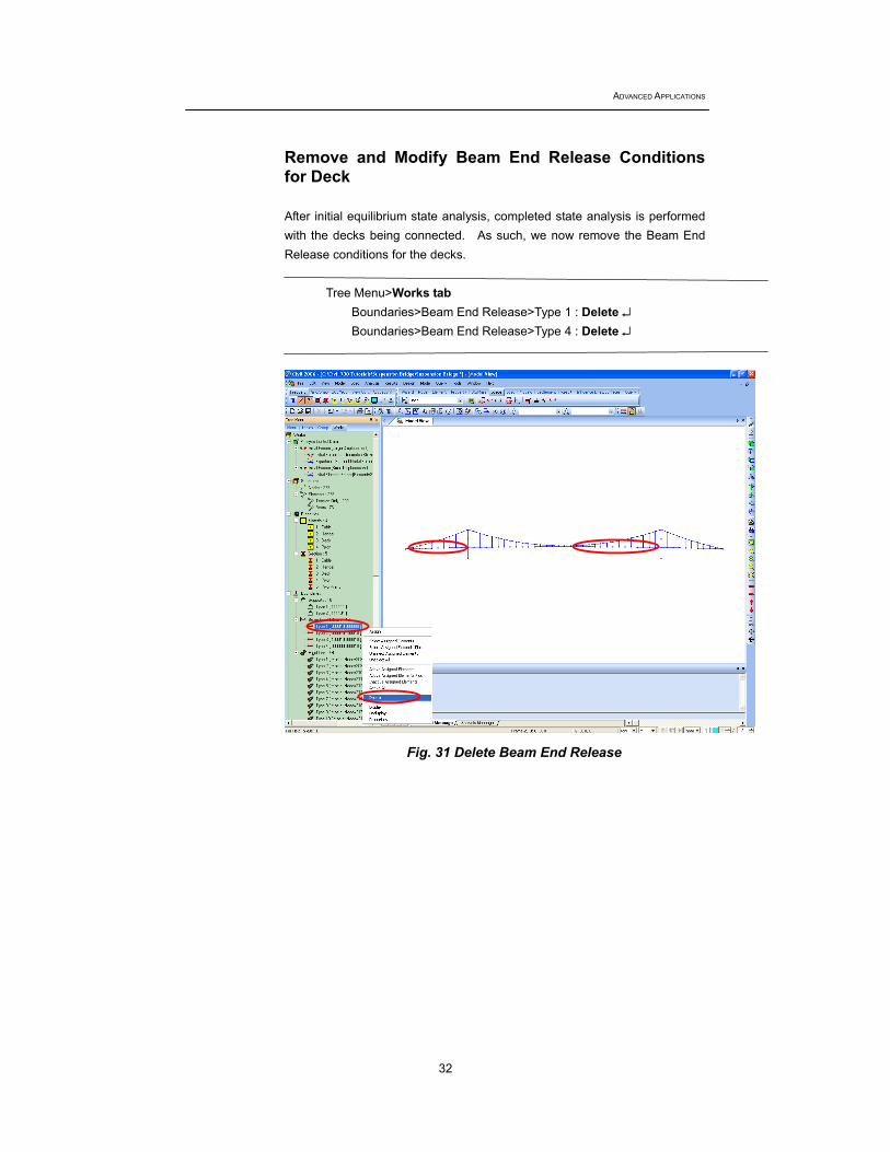
Remove and Modify Beam End Release Conditions for Deck After initial equilibrium state analysis, completed state analysis is performed with the decks being connected. As such, we now remove the Beam End Release conditions for the decks.
Tree Menu>Works tab
Boundaries>Beam End Release>Type 1 : Delete ↵ Boundaries>Beam End Release>Type 4 : Delete ↵
Fig. 31 Delete Beam End Release
Completed State and Construction Stage Analyses of a Suspension Bridge
33
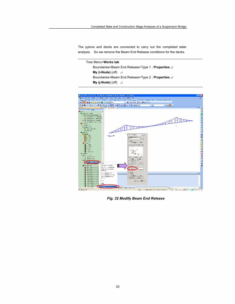
The pylons and decks are connected to carry out the completed state analysis. So we remove the Beam End Release conditions for the decks.
Tree Menu>Works tab Boundaries>Beam End Release>Type 1 : Properties ↵ My (i-Node) (off) ↵ Boundaries>Beam End Release>Type 2 : Properties ↵ My (j-Node) (off) ↵
Fig. 32 Modify Beam End Release
ADVANCED APPLICATIONS
34
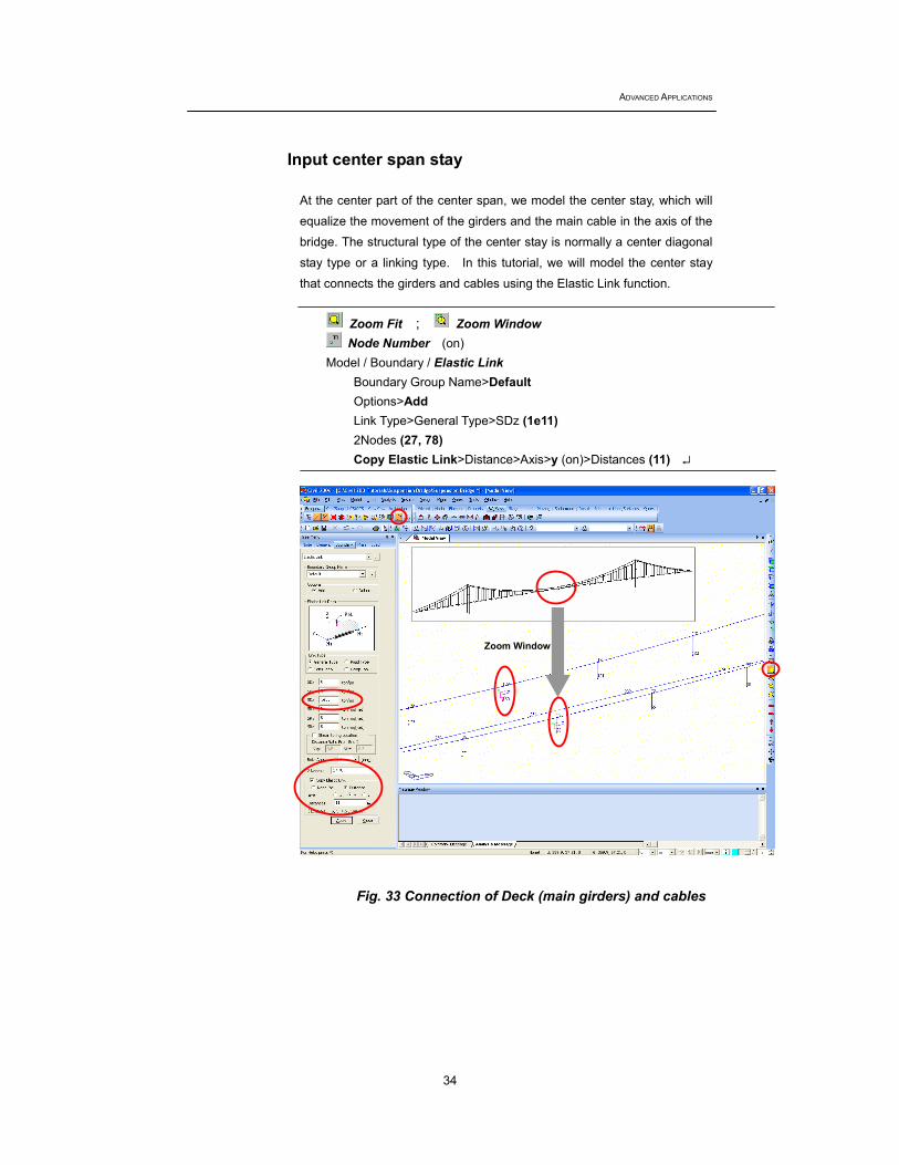
Input center span stay At the center part of the center span, we model the center stay, which will
equalize the movement of the girders and the main cable in the axis of the
bridge. The structural type of the center stay is normally a center diagonal
stay type or a linking type. In this tutorial, we will model the center stay
that connects the girders and cables using the Elastic Link function.
Zoom Fit ; Zoom Window Node Number (on)
Model / Boundary / Elastic Link Boundary Group Name>Default Options>Add Link Type>General Type>SDz (1e11) 2Nodes (27, 78) Copy Elastic Link>Distance>Axis>y (on)>Distances (11) ↵
Fig. 33 Connection of Deck (main girders) and cables
Zoom Window
Completed State and Construction Stage Analyses of a Suspension Bridge
35
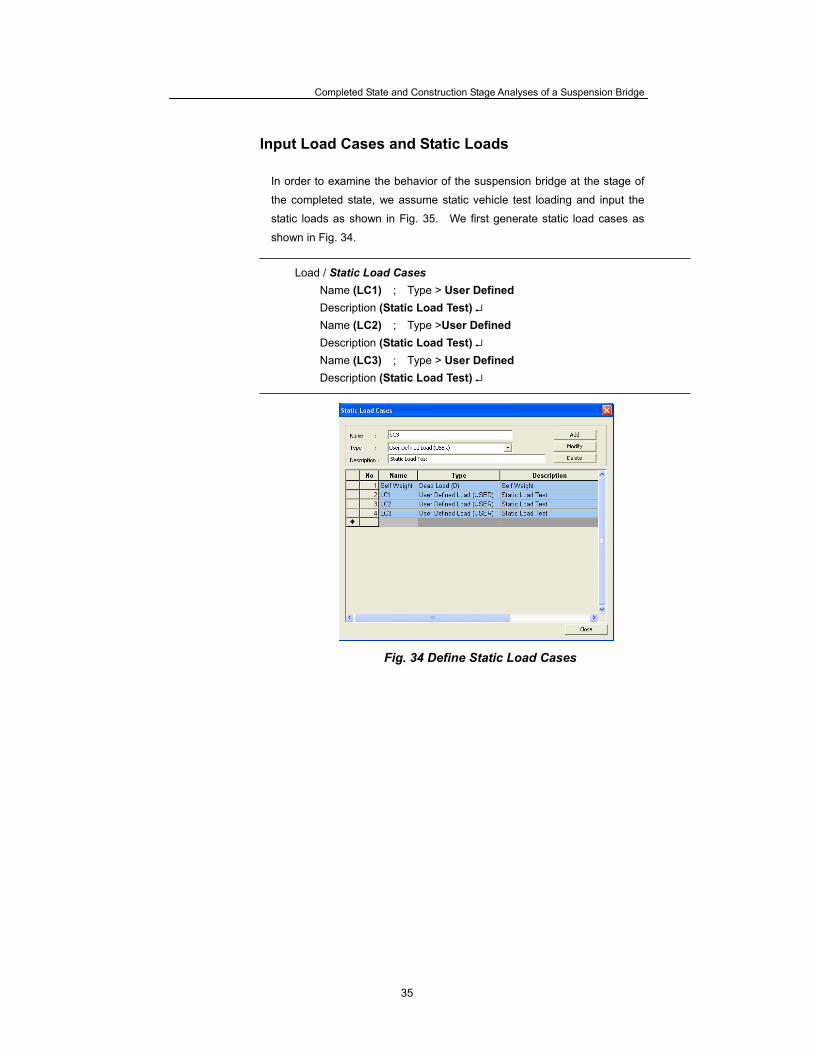
Input Load Cases and Static Loads In order to examine the behavior of the suspension bridge at the stage of
the completed state, we assume static vehicle test loading and input the
static loads as shown in Fig. 35. We first generate static load cases as
shown in Fig. 34.
Load / Static Load Cases Name (LC1) ; Type > User Defined Description (Static Load Test) ↵ Name (LC2) ; Type >User Defined Description (Static Load Test) ↵ Name (LC3) ; Type > User Defined Description (Static Load Test) ↵
Fig. 34 Define Static Load Cases
ADVANCED APPLICATIONS
36
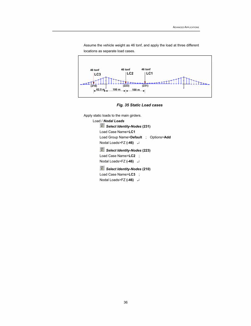
Assume the vehicle weight as 46 tonf, and apply the load at three different
locations as separate load cases.
Fig. 35 Static Load cases
Apply static loads to the main girders.
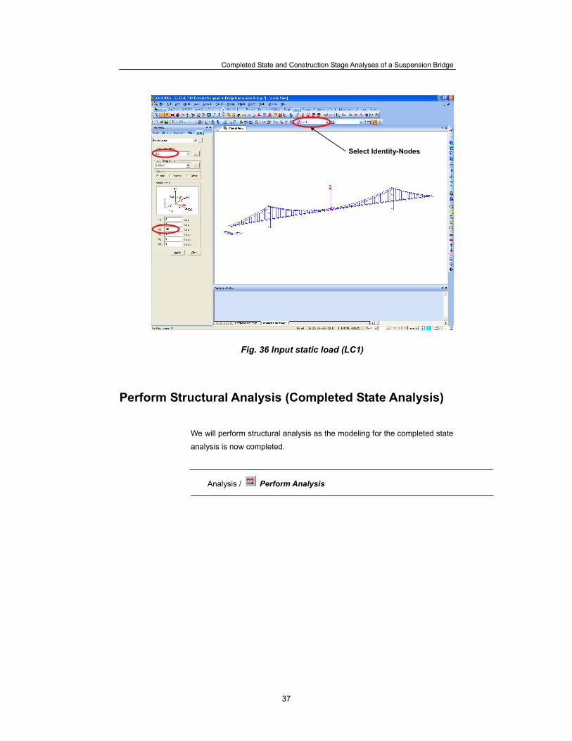
Load / Nodal Loads Select Identity-Nodes (231)
Load Case Name>LC1 Load Group Name>Default ; Options>Add Nodal Loads>FZ (-46) ↵
Select Identity-Nodes (223) Load Case Name>LC2 ; Nodal Loads>FZ (-46) ↵
Select Identity-Nodes (210) Load Case Name>LC3 ; Nodal Loads>FZ (-46) ↵
LC3 LC1 LC2
62.5 m 100 m 100 m
46 tonf 46 tonf 46 tonf
(210) (223) (231)
Completed State and Construction Stage Analyses of a Suspension Bridge
37
Fig. 36 Input static load (LC1) Perform Structural Analysis (Completed State Analysis)
We will perform structural analysis as the modeling for the completed state
analysis is now completed.
Analysis / Perform Analysis
Select Identity-Nodes
ADVANCED APPLICATIONS
38
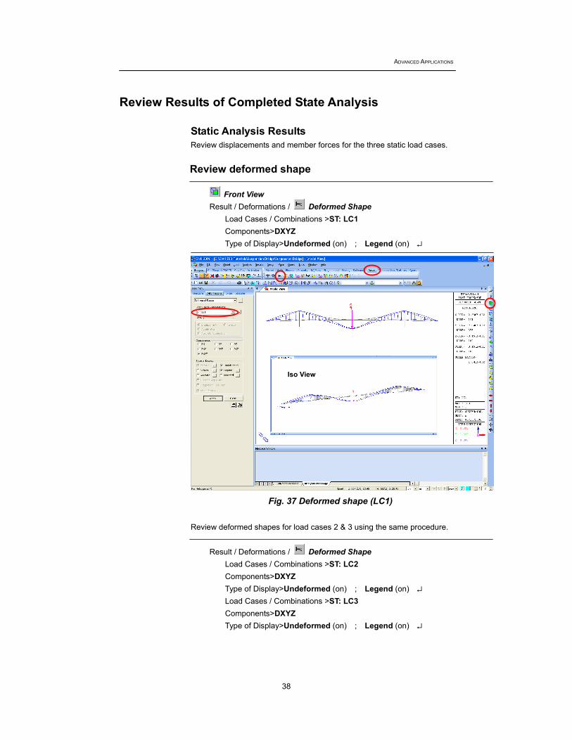
Review Results of Completed State Analysis Static Analysis Results Review displacements and member forces for the three static load cases. Review deformed shape
Front View Result / Deformations / Deformed Shape
Load Cases / Combinations >ST: LC1 Components>DXYZ Type of Display>Undeformed (on) ; Legend (on) ↵
Fig. 37 Deformed shape (LC1)
Review deformed shapes for load cases 2 & 3 using the same procedure.
Result / Deformations / Deformed Shape Load Cases / Combinations >ST: LC2 Components>DXYZ Type of Display>Undeformed (on) ; Legend (on) ↵ Load Cases / Combinations >ST: LC3 Components>DXYZ Type of Display>Undeformed (on) ; Legend (on) ↵
Iso View
Completed State and Construction Stage Analyses of a Suspension Bridge
39
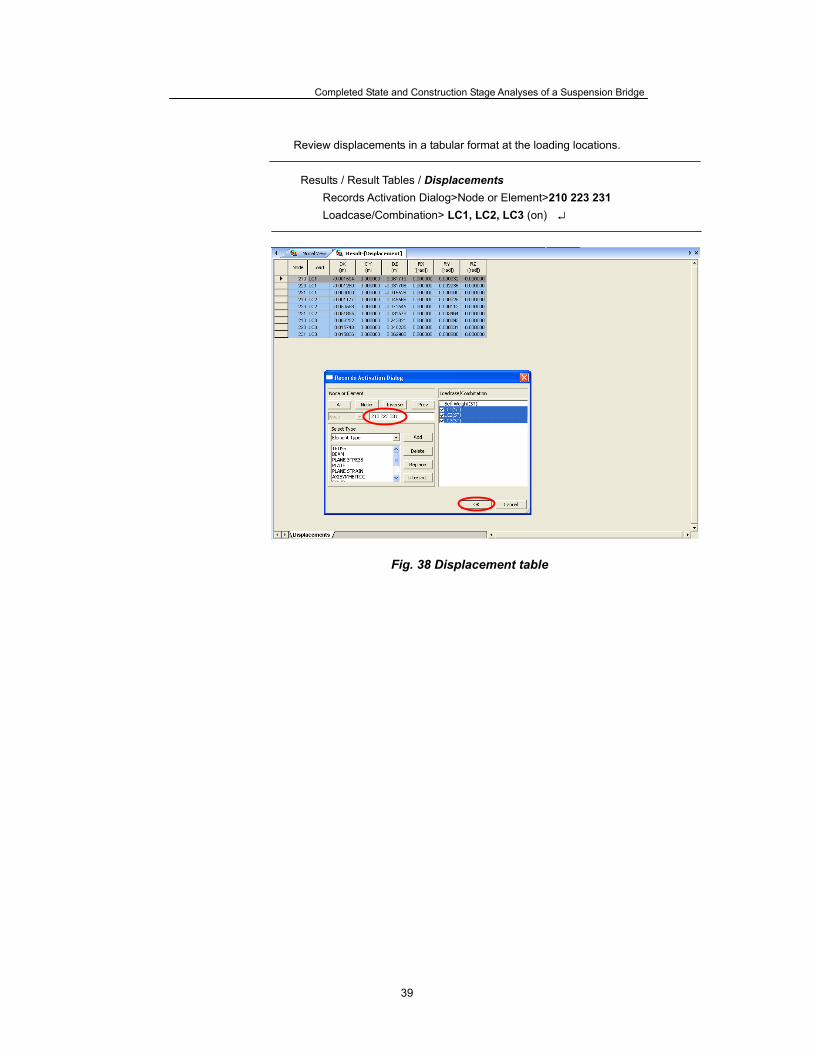
Review displacements in a tabular format at the loading locations.
Results / Result Tables / Displacements Records Activation Dialog>Node or Element>210 223 231 Loadcase/Combination> LC1, LC2, LC3 (on) ↵
Fig. 38 Displacement table
ADVANCED APPLICATIONS
40
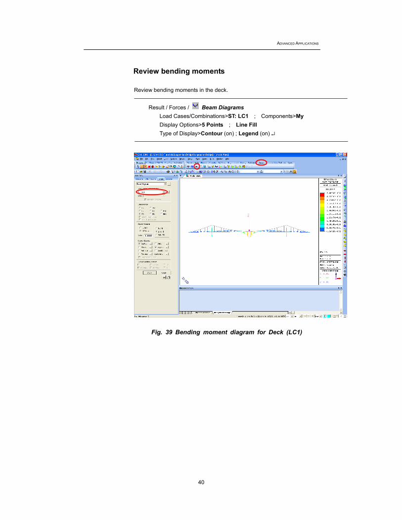
Review bending moments
Review bending moments in the deck.
Result / Forces / Beam Diagrams Load Cases/Combinations>ST: LC1 ; Components>My Display Options>5 Points ; Line Fill Type of Display>Contour (on) ; Legend (on) ↵
Fig. 39 Bending moment diagram for Deck (LC1)
Completed State and Construction Stage Analyses of a Suspension Bridge
41
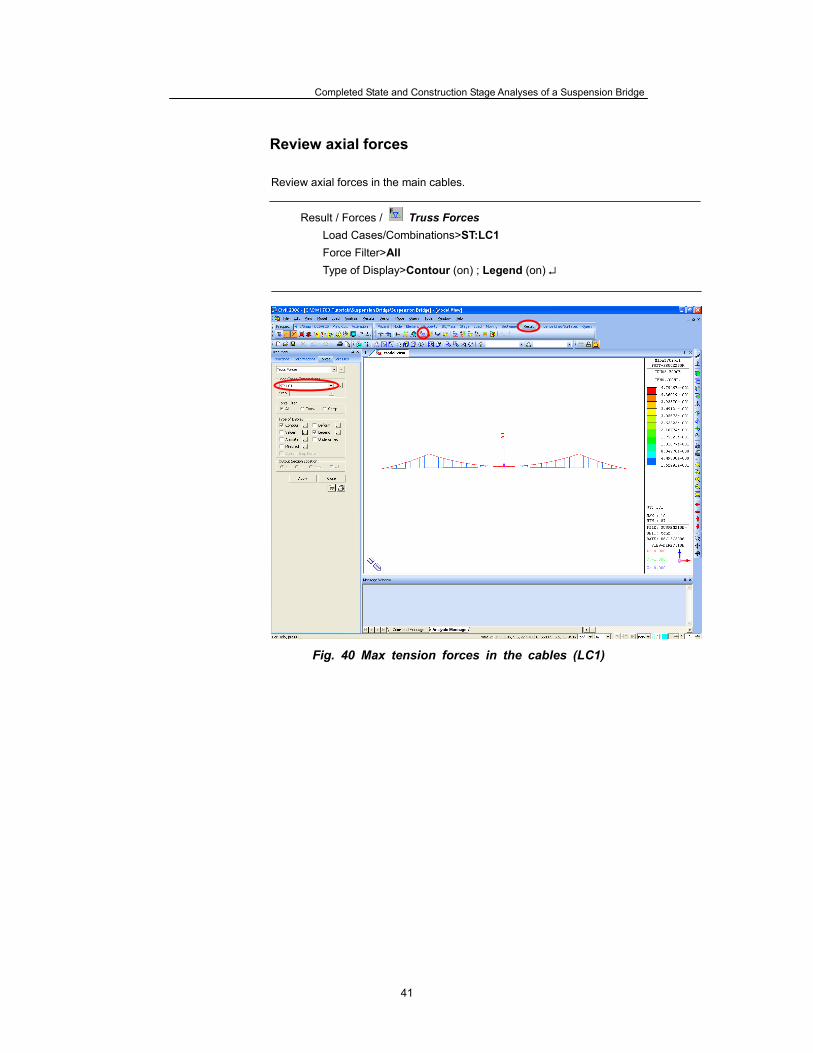
Review axial forces
Review axial forces in the main cables.
Result / Forces / Truss Forces Load Cases/Combinations>ST:LC1 Force Filter>All Type of Display>Contour (on) ; Legend (on) ↵
Fig. 40 Max tension forces in the cables (LC1)
ADVANCED APPLICATIONS
42
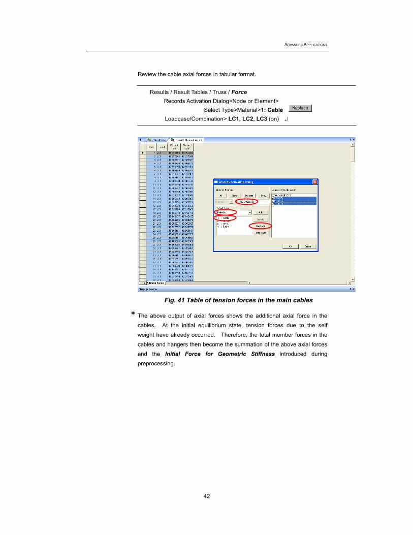
Review the cable axial forces in tabular format.
Results / Result Tables / Truss / Force Records Activation Dialog>Node or Element>
Select Type>Material>1: Cable Loadcase/Combination> LC1, LC2, LC3 (on) ↵
Fig. 41 Table of tension forces in the main cables The above output of axial forces shows the additional axial force in the
cables. At the initial equilibrium state, tension forces due to the self
weight have already occurred. Therefore, the total member forces in the
cables and hangers then become the summation of the above axial forces
and the Initial Force for Geometric Stiffness introduced during
preprocessing.
Completed State and Construction Stage Analyses of a Suspension Bridge
43
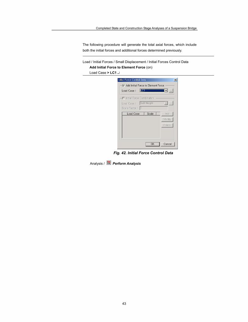
The following procedure will generate the total axial forces, which include
both the initial forces and additional forces determined previously.
Load / Initial Forces / Small Displacement / Initial Forces Control Data Add Initial Force to Element Force (on) Load Case > LC1 ↵
Fig. 42. Initial Force Control Data
Analysis / Perform Analysis

ADVANCED APPLICATIONS
44
Review the cable axial forces in the tabular format.
Results / Result Tables / Truss / Force Records Activation Dialog>Node or Element>
Select Type>Material>1: Cable Loadcase/Combination> LC1 (on) ↵
Fig. 43 Sum of initial forces and additional forces in cable
Completed State and Construction Stage Analyses of a Suspension Bridge
45
Modeling for Construction Stage Analysis
A suspension bridge is relatively unstable during construction compared
with the completed state. Therefore, geometric nonlinear analysis (large
displacement analysis) must be performed instead of linearized finite
displacement analysis or P-Delta analysis. Moreover, construction
sequence analysis is warranted to reflect the forces and displacements of
previous stages in the subsequent stages.
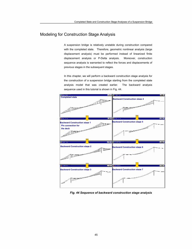
In this chapter, we will perform a backward construction stage analysis for
the construction of a suspension bridge starting from the completed state
analysis model that was created earlier. The backward analysis
sequence used in this tutorial is shown in Fig. 44.
Fig. 44 Sequence of backward construction stage analysis
Inverse Construction stage 3
Backward Construction stage 5
Backward Construction stage 6
Backward Construction stage 7
Completed state
Backward Construction stage 4
Backward Construction stage 1
Backward Construction stage 2
Backward Construction stage 3
Pin connection for the deck
ADVANCED APPLICATIONS
46
Assign Working Environment To generate a construction stage analysis model using the final stage
analysis model, we first save the completed state analysis model data under
a different file name. File / Save As (Suspension Bridge Construction.mcb) To generate a construction stage analysis model, the following should be
added to the completed state analysis model. Modeling
Define construction stages
Define elements, boundary conditions and loadings pertaining to each
construction stage.
Define Structure groups
Group elements that are added / deleted at each construction stage.
Define Boundary groups
Group boundary conditions that are added / deleted at each construction
stage.
Define Load groups
Group loads that are added / deleted at each construction stage. Analysis
Nonlinear Analysis (geometric nonlinear analysis)
Construction Stage Analysis
Completed State and Construction Stage Analyses of a Suspension Bridge
47
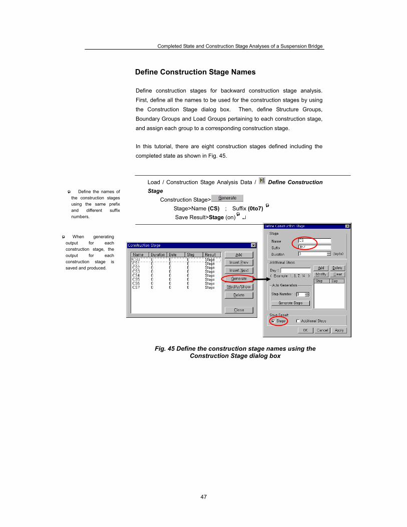
Define Construction Stage Names Define construction stages for backward construction stage analysis.
First, define all the names to be used for the construction stages by using
the Construction Stage dialog box. Then, define Structure Groups,
Boundary Groups and Load Groups pertaining to each construction stage,
and assign each group to a corresponding construction stage.
In this tutorial, there are eight construction stages defined including the
completed state as shown in Fig. 45.
Load / Construction Stage Analysis Data / Define Construction Stage
Construction Stage> Stage>Name (CS) ; Suffix (0to7) Save Result>Stage (on) ↵
Fig. 45 Define the construction stage names using the Construction Stage dialog box
When generating output for each construction stage, the output for each construction stage is saved and produced.
Define the names of the construction stages using the same prefix and different suffix numbers.
ADVANCED APPLICATIONS
48
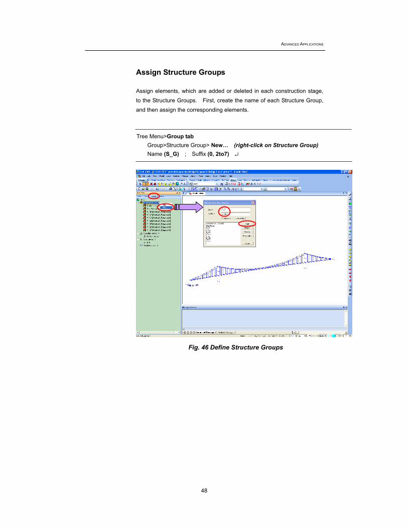
Assign Structure Groups Assign elements, which are added or deleted in each construction stage,
to the Structure Groups. First, create the name of each Structure Group,
and then assign the corresponding elements. Tree Menu>Group tab
Group>Structure Group> New… (right-click on Structure Group) Name (S_G) ; Suffix (0, 2to7) ↵
Fig. 46 Define Structure Groups
Completed State and Construction Stage Analyses of a Suspension Bridge
49
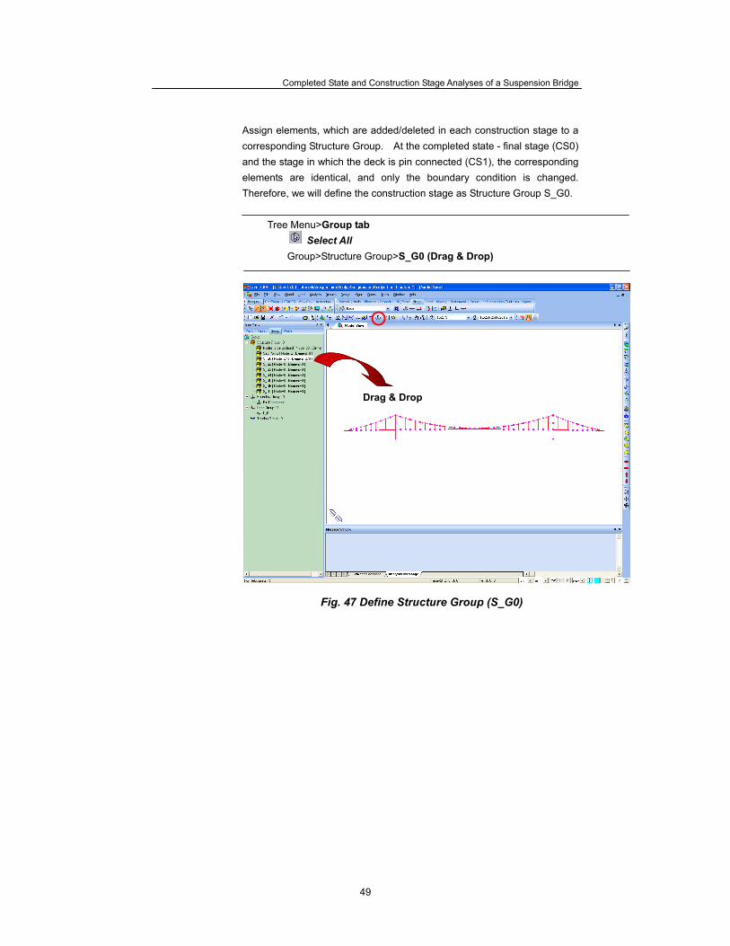
Assign elements, which are added/deleted in each construction stage to a corresponding Structure Group. At the completed state - final stage (CS0) and the stage in which the deck is pin connected (CS1), the corresponding elements are identical, and only the boundary condition is changed. Therefore, we will define the construction stage as Structure Group S_G0.
Tree Menu>Group tab Select All
Group>Structure Group>S_G0 (Drag & Drop)
Fig. 47 Define Structure Group (S_G0)
Drag & Drop
ADVANCED APPLICATIONS
50
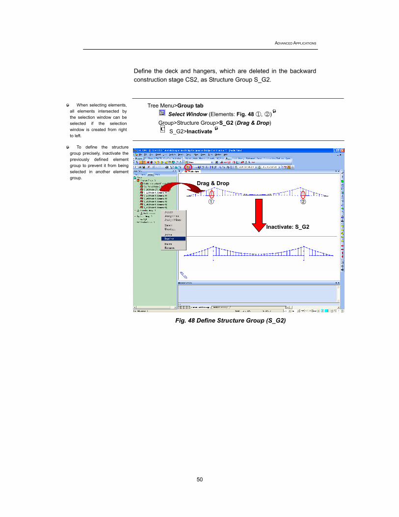
Define the deck and hangers, which are deleted in the backward construction stage CS2, as Structure Group S_G2.
Tree Menu>Group tab Select Window (Elements: Fig. 48 ①, ②)
Group>Structure Group>S_G2 (Drag & Drop) S_G2>Inactivate
Fig. 48 Define Structure Group (S_G2)
To define the structure group precisely, inactivate the previously defined element group to prevent it from being selected in another element group.
When selecting elements, all elements intersected by the selection window can be selected if the selection window is created from right to left.
C
Inactivate: S_G2
Drag & Drop
① ②
Completed State and Construction Stage Analyses of a Suspension Bridge
51
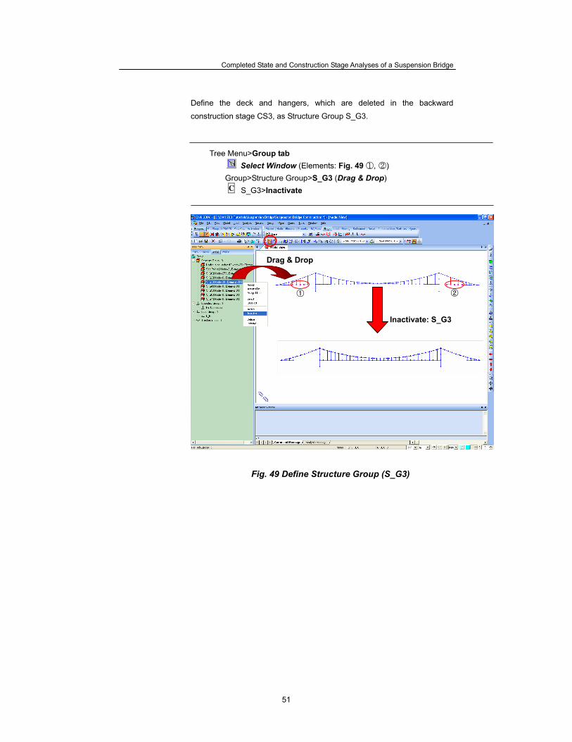
Define the deck and hangers, which are deleted in the backward
construction stage CS3, as Structure Group S_G3.
Tree Menu>Group tab Select Window (Elements: Fig. 49 ①, ②)
Group>Structure Group>S_G3 (Drag & Drop) S_G3>Inactivate
Fig. 49 Define Structure Group (S_G3)
C
Inactivate: S_G3
Drag & Drop
② ①
ADVANCED APPLICATIONS
52
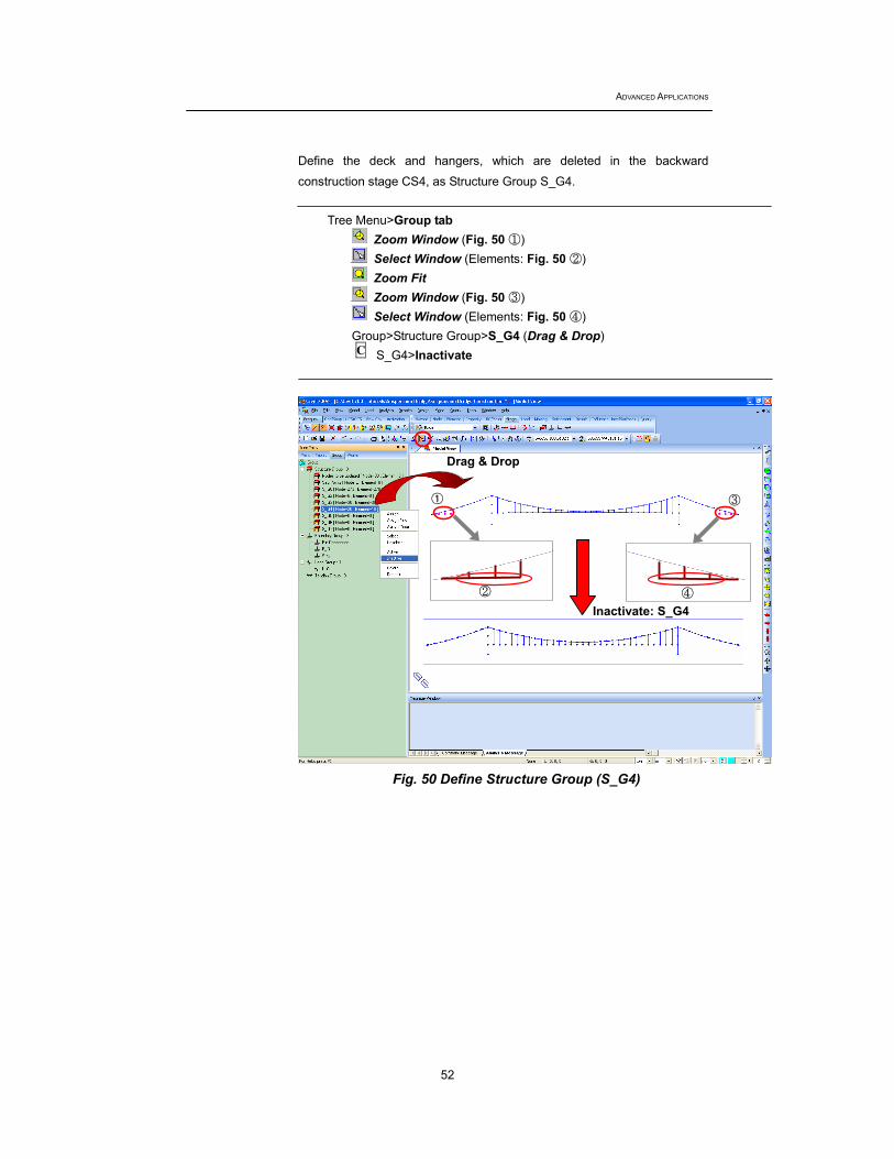
Define the deck and hangers, which are deleted in the backward
construction stage CS4, as Structure Group S_G4.
Tree Menu>Group tab Zoom Window (Fig. 50 ①) Select Window (Elements: Fig. 50 ②) Zoom Fit Zoom Window (Fig. 50 ③) Select Window (Elements: Fig. 50 ④)
Group>Structure Group>S_G4 (Drag & Drop) S_G4>Inactivate
Fig. 50 Define Structure Group (S_G4)
C
Inactivate: S_G4
③
② ④
Drag & Drop
①
Completed State and Construction Stage Analyses of a Suspension Bridge
53
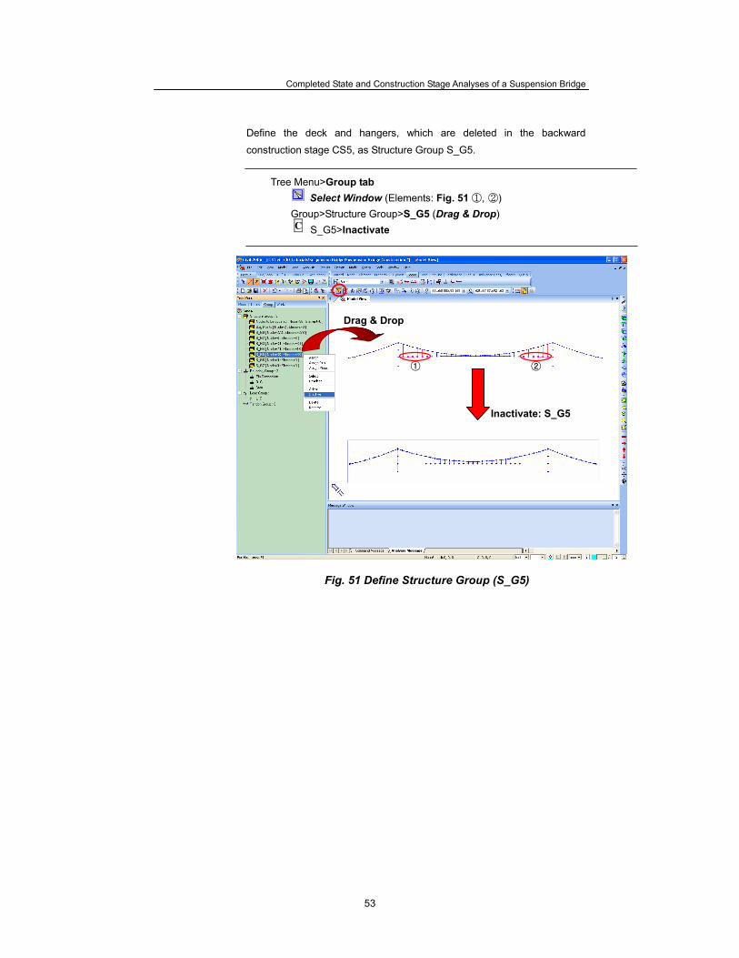
Define the deck and hangers, which are deleted in the backward
construction stage CS5, as Structure Group S_G5.
Tree Menu>Group tab Select Window (Elements: Fig. 51 ①, ②)
Group>Structure Group>S_G5 (Drag & Drop) S_G5>Inactivate
Fig. 51 Define Structure Group (S_G5)
C
Inactivate: S_G5
② ①
Drag & Drop
ADVANCED APPLICATIONS
54
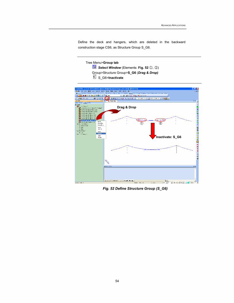
Define the deck and hangers, which are deleted in the backward
construction stage CS6, as Structure Group S_G6.
Tree Menu>Group tab Select Window (Elements: Fig. 52 ①, ②)
Group>Structure Group>S_G6 (Drag & Drop) S_G6>Inactivate
Fig. 52 Define Structure Group (S_G6)
C
① ②
Inactivate: S_G6
Drag & Drop
Completed State and Construction Stage Analyses of a Suspension Bridge
55
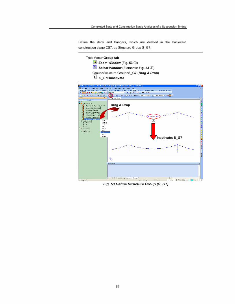
Define the deck and hangers, which are deleted in the backward
construction stage CS7, as Structure Group S_G7.
Tree Menu>Group tab Zoom Window (Fig. 53 ①) Select Window (Elements: Fig. 53 ①)
Group>Structure Group>S_G7 (Drag & Drop) S_G7>Inactivate
Fig. 53 Define Structure Group (S_G7)
C
Drag & Drop
①
Inactivate: S_G7
ADVANCED APPLICATIONS
56
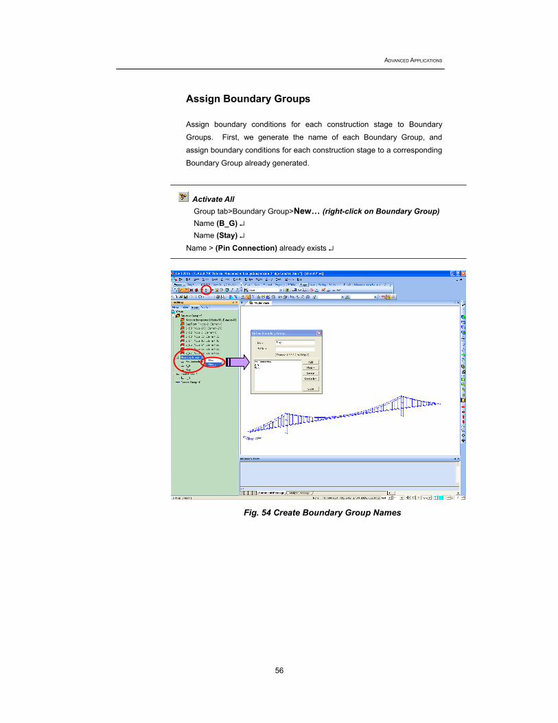
Assign Boundary Groups Assign boundary conditions for each construction stage to Boundary
Groups. First, we generate the name of each Boundary Group, and
assign boundary conditions for each construction stage to a corresponding
Boundary Group already generated.
Activate All
Group tab>Boundary Group>New… (right-click on Boundary Group) Name (B_G) ↵ Name (Stay) ↵
Name > (Pin Connection) already exists ↵
Fig. 54 Create Boundary Group Names
Completed State and Construction Stage Analyses of a Suspension Bridge
57
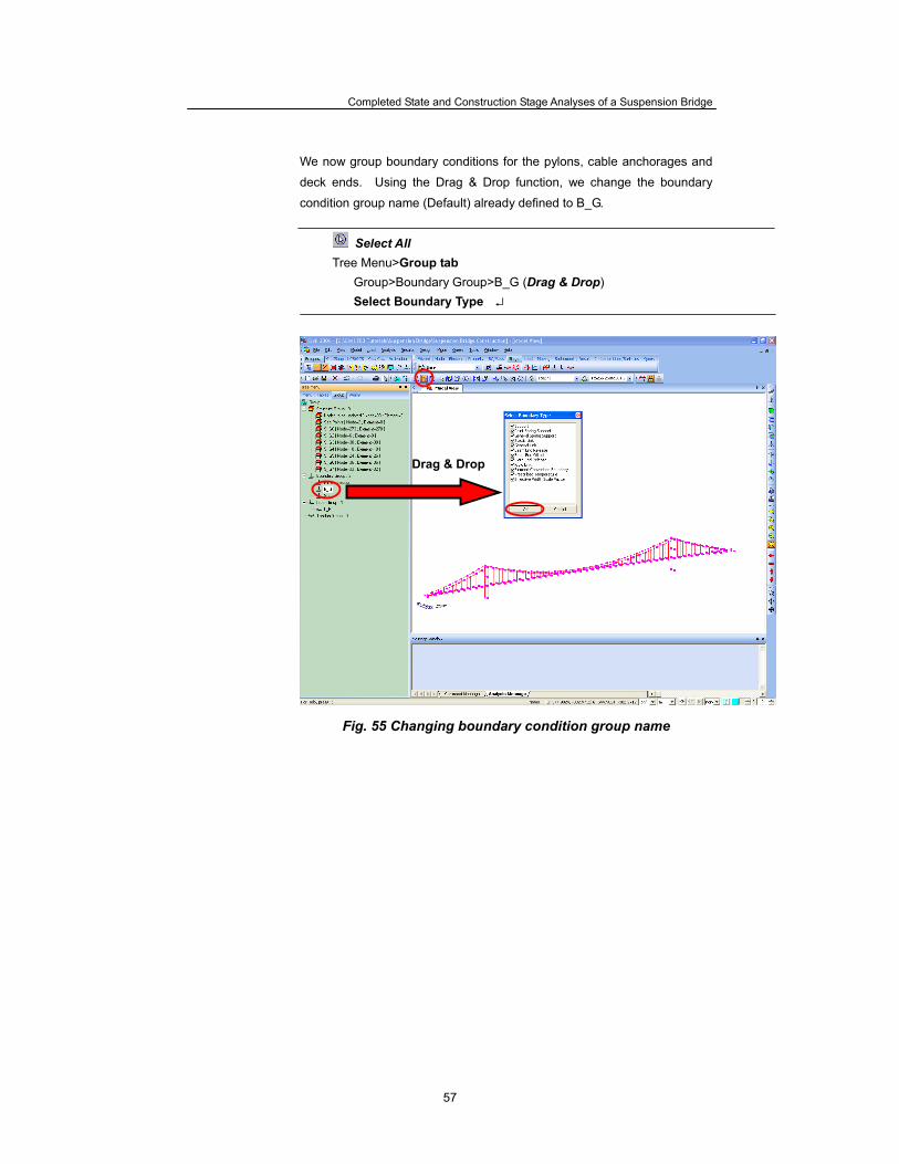
We now group boundary conditions for the pylons, cable anchorages and
deck ends. Using the Drag & Drop function, we change the boundary
condition group name (Default) already defined to B_G.
Select All
Tree Menu>Group tab Group>Boundary Group>B_G (Drag & Drop) Select Boundary Type ↵
Fig. 55 Changing boundary condition group name
Drag & Drop
ADVANCED APPLICATIONS
58
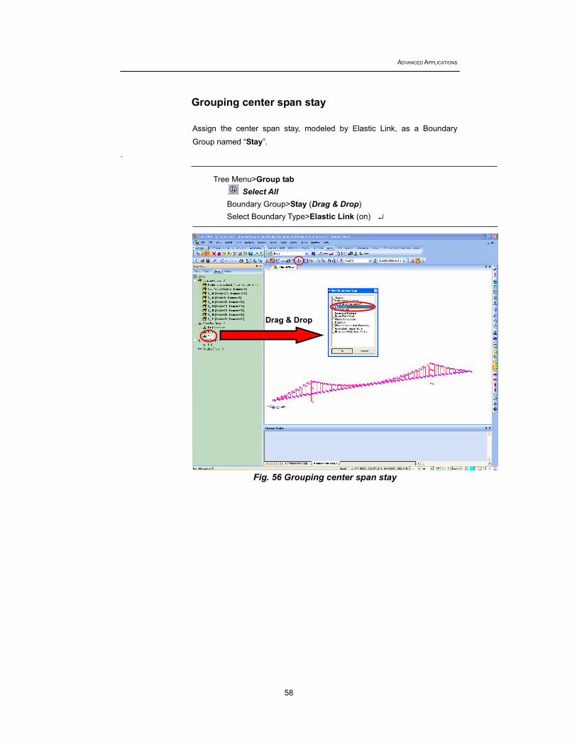
Grouping center span stay
Assign the center span stay, modeled by Elastic Link, as a Boundary
Group named “Stay”. .
Tree Menu>Group tab
Select All Boundary Group>Stay (Drag & Drop) Select Boundary Type>Elastic Link (on) ↵
Fig. 56 Grouping center span stay
Drag & Drop
Completed State and Construction Stage Analyses of a Suspension Bridge
59
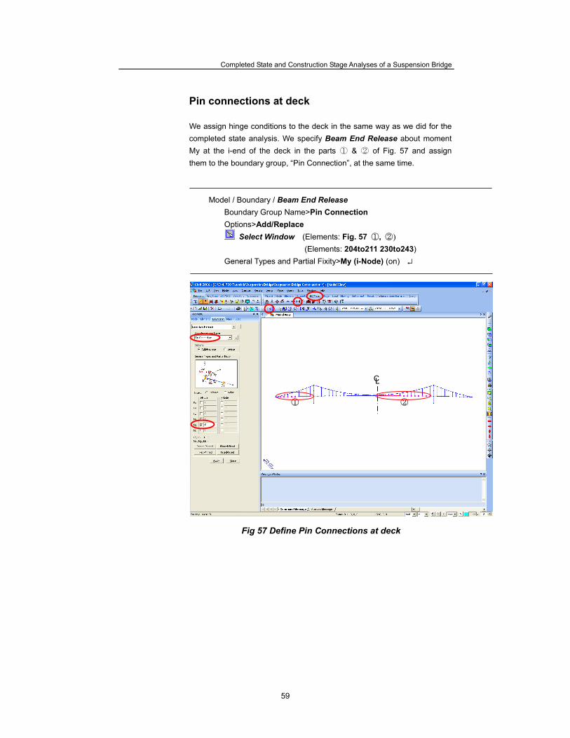
Pin connections at deck We assign hinge conditions to the deck in the same way as we did for the completed state analysis. We specify Beam End Release about moment My at the i-end of the deck in the parts ① & ② of Fig. 57 and assign them to the boundary group, “Pin Connection”, at the same time.
Model / Boundary / Beam End Release Boundary Group Name>Pin Connection Options>Add/Replace
Select Window (Elements: Fig. 57 ①, ②)
(Elements: 204to211 230to243) General Types and Partial Fixity>My (i-Node) (on) ↵
Fig 57 Define Pin Connections at deck
② ①
CL

ADVANCED APPLICATIONS
60
We specify Beam End Release about moment My at the j-end of the deck in the parts ① & ② of Fig. 58 and assign them to the boundary group, “Pin Connection”, at the same time.
Model / Boundary / Beam End Release Boundary Group Name> Pin Connection Options>Add/Replace
Select Window (Elements: Fig. 58 ①, ②)
(Elements: 214to228 246to253) General Types and Partial Fixity>My (j-Node) (on) ↵
Fig 58 Define Pin Connections at deck
② ①
CL
Completed State and Construction Stage Analyses of a Suspension Bridge
61
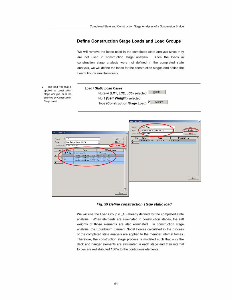
Define Construction Stage Loads and Load Groups We will remove the loads used in the completed state analysis since they
are not used in construction stage analysis. Since the loads in
construction stage analysis were not defined in the completed state
analysis, we will define the loads for the construction stages and define the
Load Groups simultaneously.
Load / Static Load Cases No 2~4 (LC1, LC2, LC3) selected No 1 (Self Weight) selected Type (Construction Stage Load)
Fig. 59 Define construction stage static load We will use the Load Group (L_G) already defined for the completed state analysis. When elements are eliminated in construction stages, the self weights of those elements are also eliminated. In construction stage analysis, the Equilibrium Element Nodal Forces calculated in the process of the completed state analysis are applied to the member internal forces. Therefore, the construction stage process is modeled such that only the deck and hanger elements are eliminated in each stage and their internal forces are redistributed 100% to the contiguous elements.
The load type that is applied to construction stage analysis must be selected as Construction Stage Load.
ADVANCED APPLICATIONS
62
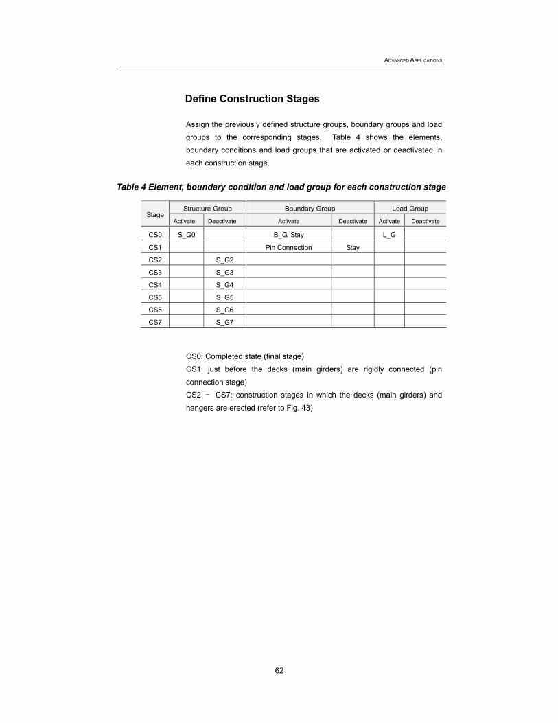
Define Construction Stages Assign the previously defined structure groups, boundary groups and load
groups to the corresponding stages. Table 4 shows the elements,
boundary conditions and load groups that are activated or deactivated in
each construction stage.
Table 4 Element, boundary condition and load group for each construction stage
CS0: Completed state (final stage)
CS1: just before the decks (main girders) are rigidly connected (pin
connection stage)
CS2 ∼ CS7: construction stages in which the decks (main girders) and
hangers are erected (refer to Fig. 43)
Structure Group Boundary Group Load Group Stage
Activate Deactivate Activate Deactivate Activate Deactivate
CS0 S_G0 B_G, Stay L_G
CS1 Pin Connection Stay
CS2 S_G2
CS3 S_G3
CS4 S_G4
CS5 S_G5
CS6 S_G6
CS7 S_G7

Completed State and Construction Stage Analyses of a Suspension Bridge
63
Define the construction stage CS0 (Completed state stage)
Load / Construction Stage Analysis Data / Define Construction Stage
Name>CS0 Save Result>Stage (on) Element>Group List>S_G0 ; Activation> Boundary> Group List> B_G, Stay ; Activation> Load>Group List>L_G ; Activation> ↵
Fig. 60 Define construction stage CS0

ADVANCED APPLICATIONS
64
Define Construction Stage CS1(Pin Connection stage). Load / Construction Stage Analysis Data / Define Construction Stage
Name>CS1 Save Result>Stage (on) Boundary> Group List> Pin Connection; Activation> Boundary> Group List> Stay ; Deactivation> ↵
Fig. 61 Define Construction Stage CS1

Completed State and Construction Stage Analyses of a Suspension Bridge
65
Define Construction Stage CS2. Load / Construction Stage Analysis Data / Define Construction Stage
Name>CS2 Save Result>Stage (on) Element> Group List> S_G2 ; Element Force Redistribution 100% ;
Deactivation>
Fig. 62 Define Construction Stage CS2
When elements are deactivated, a percentage of the internal forces of the elements being deactivated is redistributed to contiguous elements.
ADVANCED APPLICATIONS
66
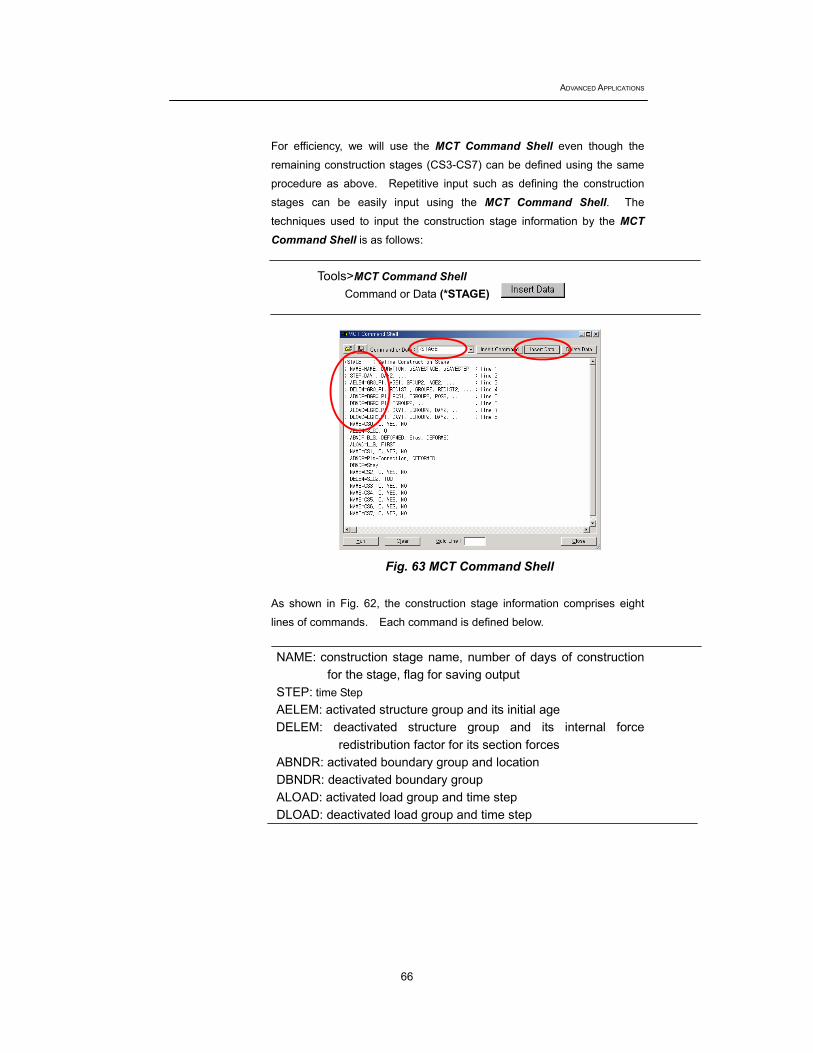
For efficiency, we will use the MCT Command Shell even though the
remaining construction stages (CS3-CS7) can be defined using the same
procedure as above. Repetitive input such as defining the construction
stages can be easily input using the MCT Command Shell. The
techniques used to input the construction stage information by the MCT Command Shell is as follows:
Tools>MCT Command Shell
Command or Data (*STAGE)
Fig. 63 MCT Command Shell
As shown in Fig. 62, the construction stage information comprises eight
lines of commands. Each command is defined below.
NAME: construction stage name, number of days of construction for the stage, flag for saving output
STEP: time Step AELEM: activated structure group and its initial age
DELEM: deactivated structure group and its internal force redistribution factor for its section forces
ABNDR: activated boundary group and location DBNDR: deactivated boundary group ALOAD: activated load group and time step DLOAD: deactivated load group and time step
Completed State and Construction Stage Analyses of a Suspension Bridge
67
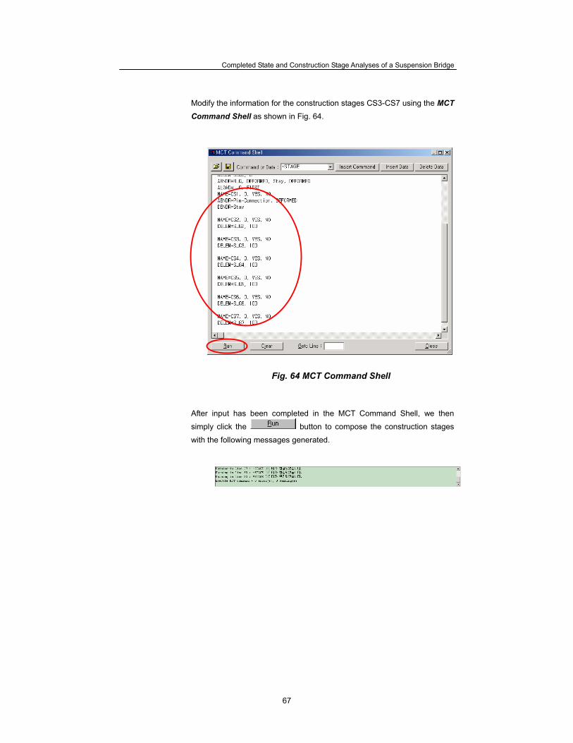
Modify the information for the construction stages CS3-CS7 using the MCT Command Shell as shown in Fig. 64.
Fig. 64 MCT Command Shell
After input has been completed in the MCT Command Shell, we then
simply click the button to compose the construction stages
with the following messages generated.
ADVANCED APPLICATIONS
68
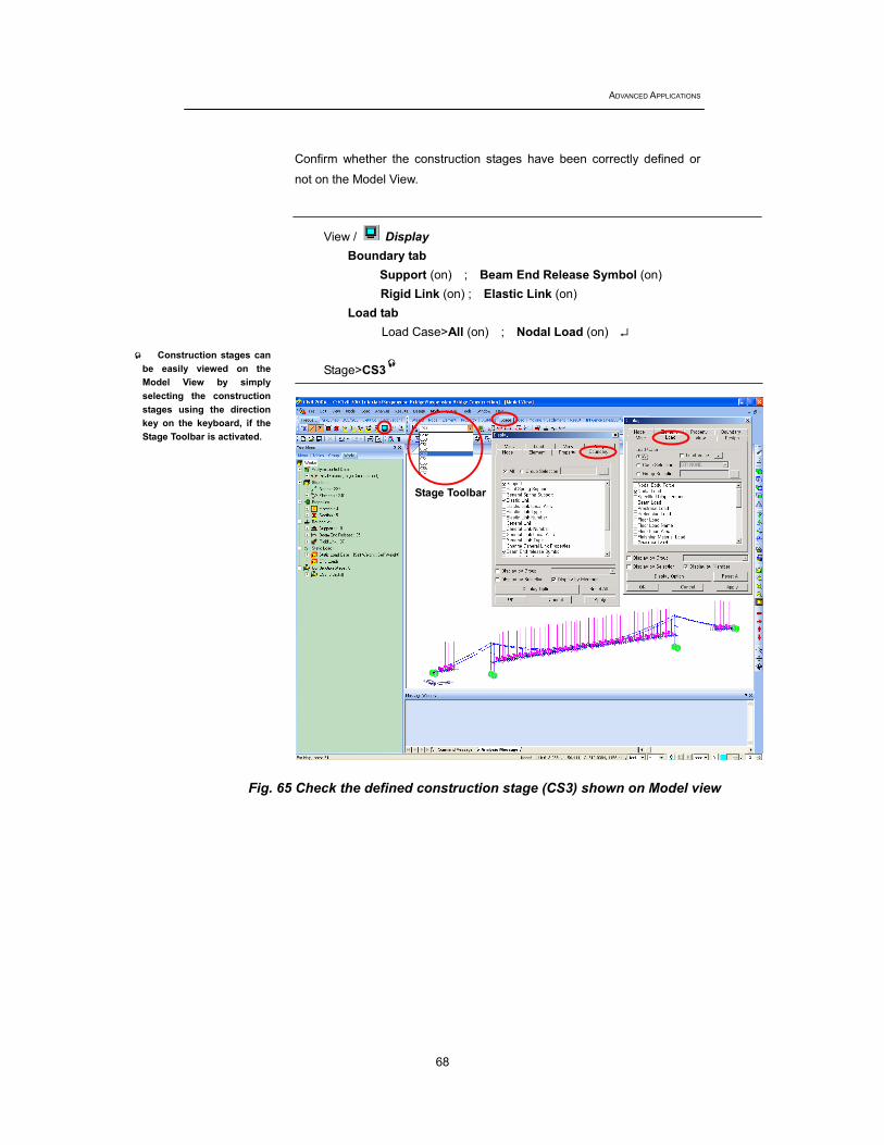
Confirm whether the construction stages have been correctly defined or
not on the Model View.
View / Display Boundary tab
Support (on) ; Beam End Release Symbol (on) Rigid Link (on) ; Elastic Link (on)
Load tab Load Case>All (on) ; Nodal Load (on) ↵
Stage>CS3
Fig. 65 Check the defined construction stage (CS3) shown on Model view
Construction stages can be easily viewed on the Model View by simply selecting the construction stages using the direction key on the keyboard, if the Stage Toolbar is activated.
Stage Toolbar
Completed State and Construction Stage Analyses of a Suspension Bridge
69
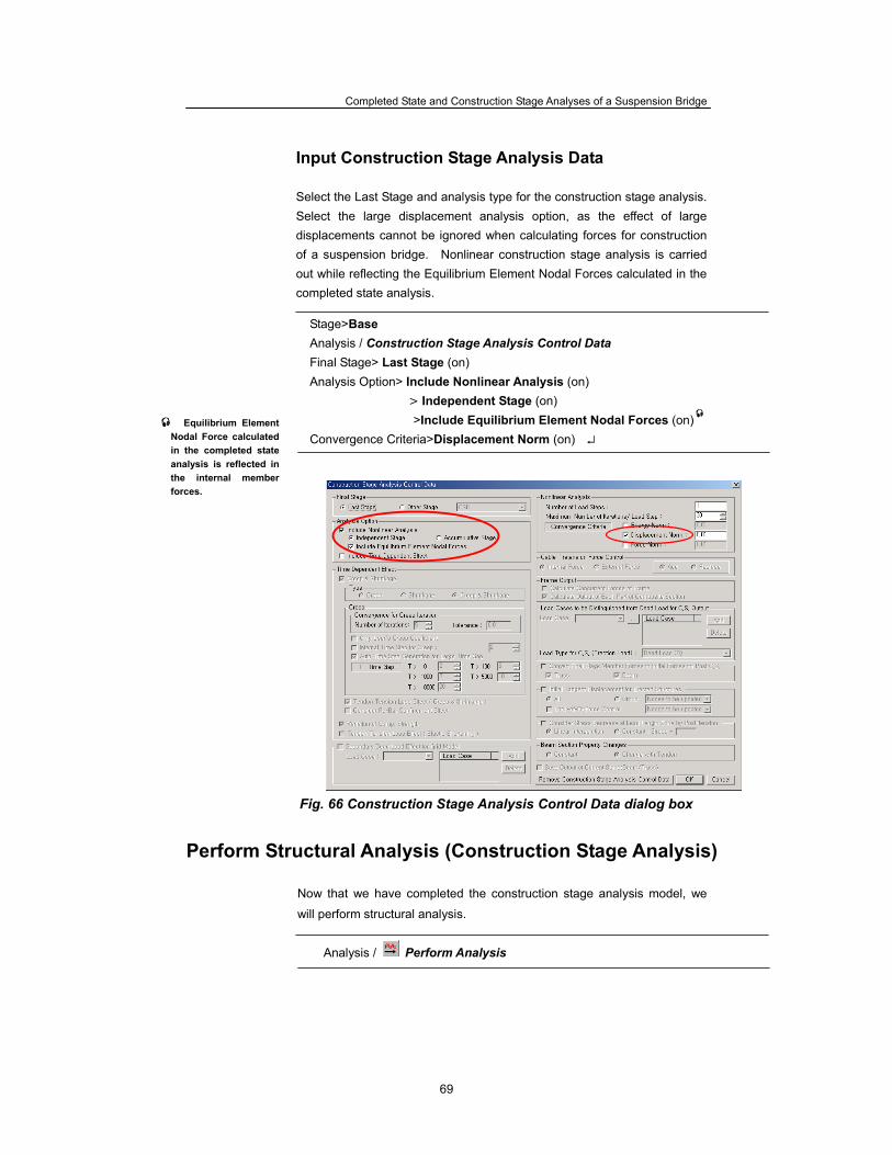
Input Construction Stage Analysis Data
Select the Last Stage and analysis type for the construction stage analysis. Select the large displacement analysis option, as the effect of large displacements cannot be ignored when calculating forces for construction of a suspension bridge. Nonlinear construction stage analysis is carried out while reflecting the Equilibrium Element Nodal Forces calculated in the completed state analysis.
Stage>Base Analysis / Construction Stage Analysis Control Data Final Stage> Last Stage (on) Analysis Option> Include Nonlinear Analysis (on) > Independent Stage (on)
>Include Equilibrium Element Nodal Forces (on) Convergence Criteria>Displacement Norm (on) ↵
Fig. 66 Construction Stage Analysis Control Data dialog box Perform Structural Analysis (Construction Stage Analysis)
Now that we have completed the construction stage analysis model, we
will perform structural analysis.
Analysis / Perform Analysis
Equilibrium Element Nodal Force calculated in the completed state analysis is reflected in the internal member forces.
ADVANCED APPLICATIONS
70
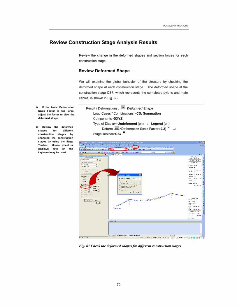
Review Construction Stage Analysis Results
Review the change in the deformed shapes and section forces for each
construction stage. Review Deformed Shape We will examine the global behavior of the structure by checking the
deformed shape at each construction stage. The deformed shape at the
construction stage CS7, which represents the completed pylons and main
cables, is shown in Fig. 66.
Result / Deformations / Deformed Shape Load Cases / Combinations >CS: Summation Components>DXYZ Type of Display>Undeformed (on) ; Legend (on)
Deform >Deformation Scale Factor (0.2) ↵ Stage Toolbar>CS7
Fig. 67 Check the deformed shapes for different construction stages
Review the deformed shapes for different construction stages by changing the construction stages by using the Stage Toolbar. Mouse wheel or up/down keys on the keyboard may be used.
If the basic Deformation Scale Factor is too large, adjust the factor to view the deformed shape.
Completed State and Construction Stage Analyses of a Suspension Bridge
71
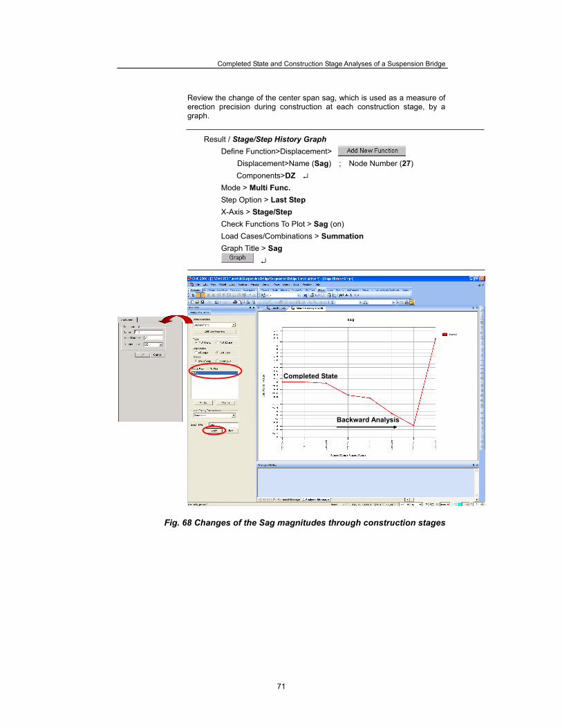
Review the change of the center span sag, which is used as a measure of erection precision during construction at each construction stage, by a graph.
Result / Stage/Step History Graph Define Function>Displacement>
Displacement>Name (Sag) ; Node Number (27) Components>DZ ↵
Mode > Multi Func. Step Option > Last Step X-Axis > Stage/Step Check Functions To Plot > Sag (on) Load Cases/Combinations > Summation Graph Title > Sag
↵
Fig. 68 Changes of the Sag magnitudes through construction stages
Completed State
Backward Analysis

ADVANCED APPLICATIONS
72
Determine a setback Review the magnitude of a setback for the pylons at the stage when the
deck (main girders) and hangers have not been erected.
Result / Deformations / Deformed Shape Stage Toolbar>CS7 Load Cases / Combinations >CS: Summation Components>DX Type of Display>Undeformed (on) ; Legend (on) ↵
Fig. 69 Review setback value
Setback value
Suspension bridges are designed to have no bending moments in pylons
at the completed state stage by maintaining the applied horizontal forces in
equilibrium at the tops of the pylons. However, if the cable is erected with
the same center span length of the completed state stage, the resulting
horizontal forces at the tops of the pylons are not in an equilibrium
condition, and hence, cable slip will likely occur. The tops of the pylons
are relocated (a type of horizontal camber) to set the horizontal cable
forces balanced left and right. Generally, the tops of the pylons are pulled
toward the side spans by wire ropes, and this is called setback.
*

Completed State and Construction Stage Analyses of a Suspension Bridge
73
We will now review the horizontal displacements changing with the construction stages at the top of a pylon by using a graph. As shown in Fig. 69, the horizontal displacement in backward construction stage CS7 becomes the setback value of the pylons.
Result / Stage / Step History Graph Define Function>Displacement>
Displacement>Name (Right Tower) ; Node Number (43)
Components>DX ↵ Mode > Multi Func. Step Option > Last Step X-Axis > Stage/Step Check Functions To Plot>Right Tower
Graph Title (Right Tower Displacement) ↵
Fig. 70 Horizontal displacements of a pylon with changing construction stages
Backward Analysis
Setback Value
Completed State Stage
ADVANCED APPLICATIONS
74
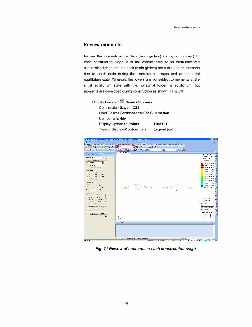
Review moments Review the moments in the deck (main girders) and pylons (towers) for
each construction stage. It is the characteristic of an earth-anchored
suspension bridge that the deck (main girders) are subject to no moments
due to dead loads during the construction stages and at the initial
equilibrium state. Whereas, the towers are not subject to moments at the
initial equilibrium state with the horizontal forces in equilibrium, but
moments are developed during construction as shown in Fig. 70.
Result / Forces / Beam Diagrams Construction Stage > CS2 Load Cases>Combinations>CS: Summation Components>My Display Options>5 Points ; Line Fill Type of Display>Contour (on) ; Legend (on) ↵
Fig. 71 Review of moments at each construction stage

Completed State and Construction Stage Analyses of a Suspension Bridge
75
Review axial forces Review axial forces in the main cables & hangers for each construction
stage.
Result / Forces / Truss Forces Construction Stage > CS2 Load Cases / Combinations>CS: Summation Force Filter>All Type of Display>Contour (on) ; Legend (on) ↵
Fig. 72 Review of axial forces in the main cables and hangers
ADVANCED APPLICATIONS
76
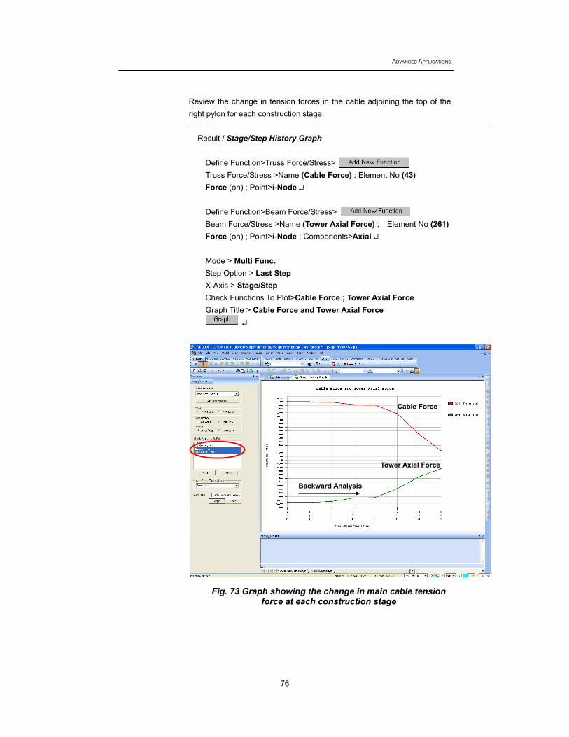
Review the change in tension forces in the cable adjoining the top of the right pylon for each construction stage.
Result / Stage/Step History Graph Define Function>Truss Force/Stress> Truss Force/Stress >Name (Cable Force) ; Element No (43) Force (on) ; Point>i-Node ↵ Define Function>Beam Force/Stress> Beam Force/Stress >Name (Tower Axial Force) ; Element No (261) Force (on) ; Point>i-Node ; Components>Axial ↵ Mode > Multi Func. Step Option > Last Step X-Axis > Stage/Step Check Functions To Plot>Cable Force ; Tower Axial Force Graph Title > Cable Force and Tower Axial Force
↵
Fig. 73 Graph showing the change in main cable tension
force at each construction stage
Cable Force
Tower Axial Force
Backward Analysis
Completed State and Construction Stage Analyses of a Suspension Bridge
77
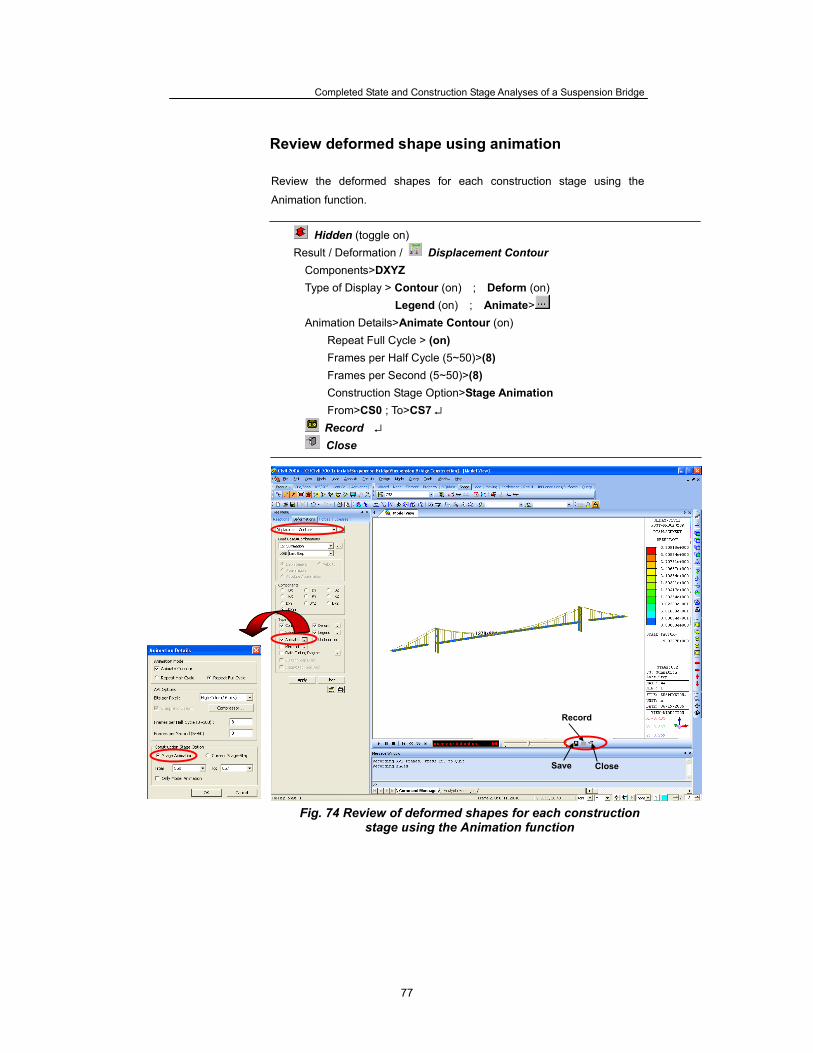
Review deformed shape using animation Review the deformed shapes for each construction stage using the
Animation function.
Hidden (toggle on) Result / Deformation / Displacement Contour
Components>DXYZ Type of Display > Contour (on) ; Deform (on)
Legend (on) ; Animate> Animation Details>Animate Contour (on)
Repeat Full Cycle > (on) Frames per Half Cycle (5~50)>(8) Frames per Second (5~50)>(8) Construction Stage Option>Stage Animation From>CS0 ; To>CS7 ↵
Record ↵ Close
Fig. 74 Review of deformed shapes for each construction stage using the Animation function
Close Save
Record