vector mechanics for engineers: dynamicseng.sut.ac.th/me/2014/document/engdynamics/17_lecture... ·...
TRANSCRIPT
VECTOR MECHANICS FOR ENGINEERS:
DYNAMICS
Tenth Edition
Ferdinand P. Beer
E. Russell Johnston, Jr.
Phillip J. Cornwell
Lecture Notes:
Brian P. SelfCalifornia State Polytechnic University
CHAPTER
© 2013 The McGraw-Hill Companies, Inc. All rights reserved.
17Plane Motion of Rigid
Bodies:
Energy and Momentum
Methods
Plane Motion of Rigid
Bodies: Energy and
Momentum Methods

© 2013 The McGraw-Hill Companies, Inc. All rights reserved.
Vector Mechanics for Engineers: Dynamics
Ten
thE
ditio
n
Contents
17 - 2
Introduction
Principle of Work and Energy for a
Rigid Body
Work of Forces Acting on a Rigid Body
Kinetic Energy of a Rigid Body in Plane
Motion
Systems of Rigid Bodies
Conservation of Energy
Power
Sample Problem 17.1
Sample Problem 17.2
Sample Problem 17.3
Sample Problem 17.4
Sample Problem 17.5
Principle of Impulse and Momentum
Systems of Rigid Bodies
Conservation of Angular Momentum
Sample Problem 17.6
Sample Problem 17.7
Sample Problem 17.8
Eccentric Impact
Sample Problem 17.9
Sample Problem 17.10
Sample Problem 17.11

© 2013 The McGraw-Hill Companies, Inc. All rights reserved.
Vector Mechanics for Engineers: Dynamics
Ten
thE
ditio
n
Introduction
17 - 3
To predict the launch from a catapult, you
must apply the principle of work-energy.
To determine the forces acting on the stopper pin when the
catapult reaches its final position, angular impulse momentum
equations are used.
© 2013 The McGraw-Hill Companies, Inc. All rights reserved.
Vector Mechanics for Engineers: Dynamics
Ten
thE
ditio
n
Introduction
17 - 4
• Method of work and energy and the method of impulse and
momentum will be used to analyze the plane motion of rigid
bodies and systems of rigid bodies.
• Principle of work and energy is well suited to the solution of
problems involving displacements and velocities.
2211 TUT
• Principle of impulse and momentum is appropriate for
problems involving velocities and time.
2121
2
1
2
1
O
t
tOO
t
t
HdtMHLdtFL
• Problems involving eccentric impact are solved by supplementing
the principle of impulse and momentum with the application of
the coefficient of restitution.

© 2013 The McGraw-Hill Companies, Inc. All rights reserved.
Vector Mechanics for Engineers: Dynamics
Ten
thE
ditio
n
Introduction
17 - 5
Forces and
Accelerations
Velocities and
Displacements
Velocities and
Time
Approaches to Rigid Body Kinetics Problems
Newton’s Second
Law (last chapter)
Work-Energy Impulse-
Momentum
2211 TUT
Få =maG
MGå = H
G
mv1+ F dt
t1
t2
ò =mv2
2
11 2
t
G G Gt
I M dt I

© 2013 The McGraw-Hill Companies, Inc. All rights reserved.
Vector Mechanics for Engineers: Dynamics
Ten
thE
ditio
n
Principle of Work and Energy for a Rigid Body
17 - 6
•Work and kinetic energy are scalar quantities.
• Assume that the rigid body is made of a large
number of particles.
2211 TUT
21, TT
21U
initial and final total kinetic energy of
particles forming body
total work of internal and external forces
acting on particles of body.
• Internal forces between particles A
and B are equal and opposite.
• Therefore, the net work of internal
forces is zero.

© 2013 The McGraw-Hill Companies, Inc. All rights reserved.
Vector Mechanics for Engineers: Dynamics
Ten
thE
ditio
n
Work of Forces Acting on a Rigid Body
17 - 7
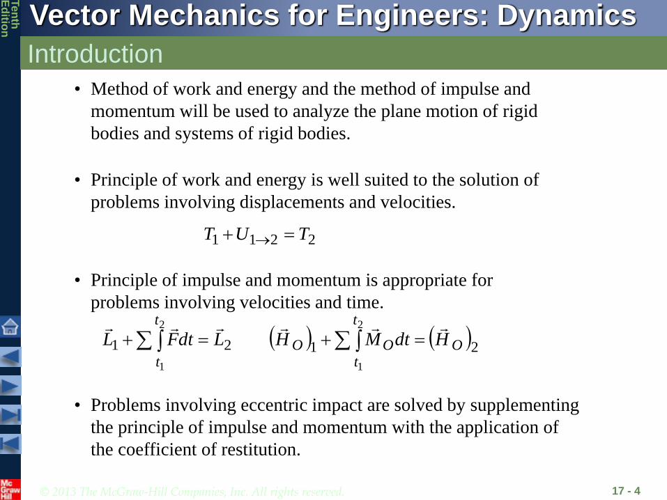
• Work of a force during a displacement of its
point of application,
2
1
2
1
cos21
s
s
A
A
dsFrdFU
• Consider the net work of two forces
forming a couple of moment during a
displacement of their points of application.
FF
and
M
dM
dFrdsF
rdFrdFrdFdU
2
211
12
21
2
1
M
dMU
if M is constant.
© 2013 The McGraw-Hill Companies, Inc. All rights reserved.
Vector Mechanics for Engineers: Dynamics
Ten
thE
ditio
n
Work of Forces Acting on a Rigid Body
17 - 8
Do the pin forces at point
A do work?
YES NO
Does the force P do work?
YES NO

© 2013 The McGraw-Hill Companies, Inc. All rights reserved.
Vector Mechanics for Engineers: Dynamics
Ten
thE
ditio
n
Work of Forces Acting on a Rigid Body
17 - 9
Does the normal force N
do work on the disk?
YES NO
Does the weight W do work?
YES NO
If the disk rolls without slip, does
the friction force F do work?
YES NO
0 dtvFdsFdU cC
© 2013 The McGraw-Hill Companies, Inc. All rights reserved.
Vector Mechanics for Engineers: Dynamics
Ten
thE
ditio
n
Kinetic Energy of a Rigid Body in Plane Motion
17 - 10
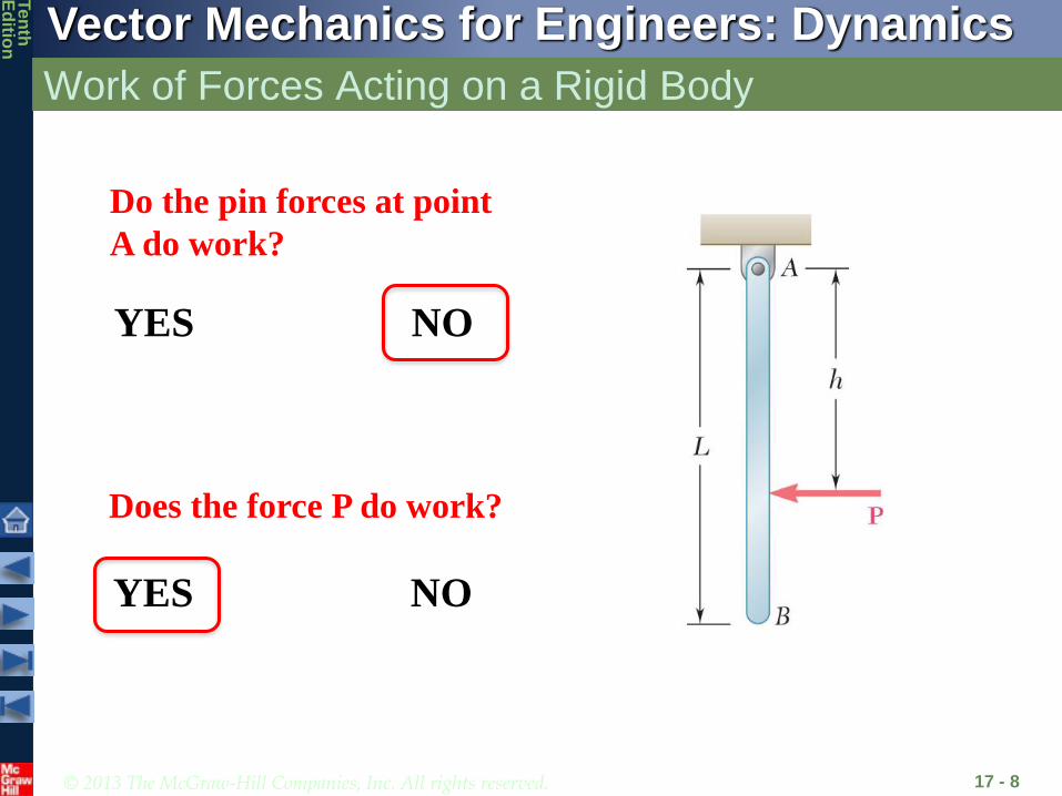
• Consider a rigid body of mass m in plane motion consisting of individual
particles i. The kinetic energy of the body can then be expressed as:
2 21 12 2
2 2 21 12 2
2 21 12 2
Δ
Δ
i i
i i
T mv m v
mv r m
mv I
• Kinetic energy of a rigid body can be
separated into:
- the kinetic energy associated with the
motion of the mass center G and
- the kinetic energy associated with the
rotation of the body about G.
2 21 12 2
T mv I
Translation + Rotation
© 2013 The McGraw-Hill Companies, Inc. All rights reserved.
Vector Mechanics for Engineers: Dynamics
Ten
thE
ditio
n
Kinetic Energy of a Rigid Body in Plane Motion
17 - 11
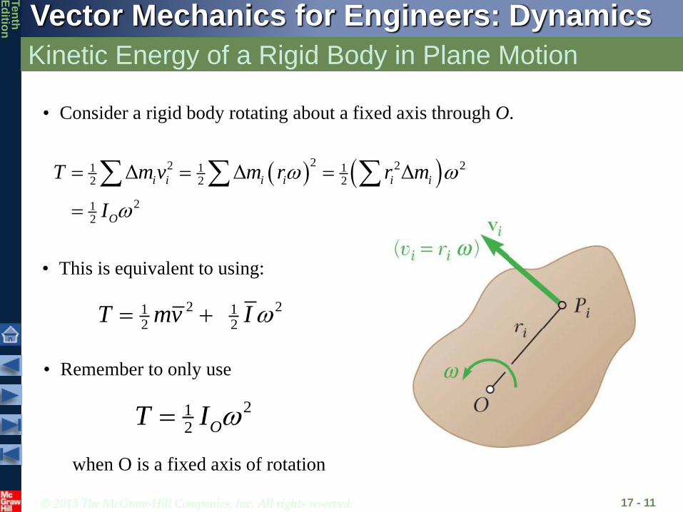
• Consider a rigid body rotating about a fixed axis through O.
22 2 21 1 1
2 2 2
212
Δ Δ Δi i i i i i
O
T m v m r r m
I
• This is equivalent to using:
2 21 12 2
T mv I
212 OT I
• Remember to only use
when O is a fixed axis of rotation

© 2013 The McGraw-Hill Companies, Inc. All rights reserved.
Vector Mechanics for Engineers: Dynamics
Ten
thE
ditio
n
Concept Quiz
17 - 12
The solid cylinder A and the pipe B
have the same diameter and mass.
If they are both released from rest
at the top of the hill, which will
reach the bottom the fastest?
B
A
a) A will reach the bottom first
b) B will reach the bottom first
c) They will reach the bottom
at the same time
Which will have the greatest
kinetic energy when it reaches the
bottom?
a) Cylinder A b) Pipe B c) Same kinetic energy
© 2013 The McGraw-Hill Companies, Inc. All rights reserved.
Vector Mechanics for Engineers: Dynamics
Ten
thE
ditio
n
Systems of Rigid Bodies
17 - 13
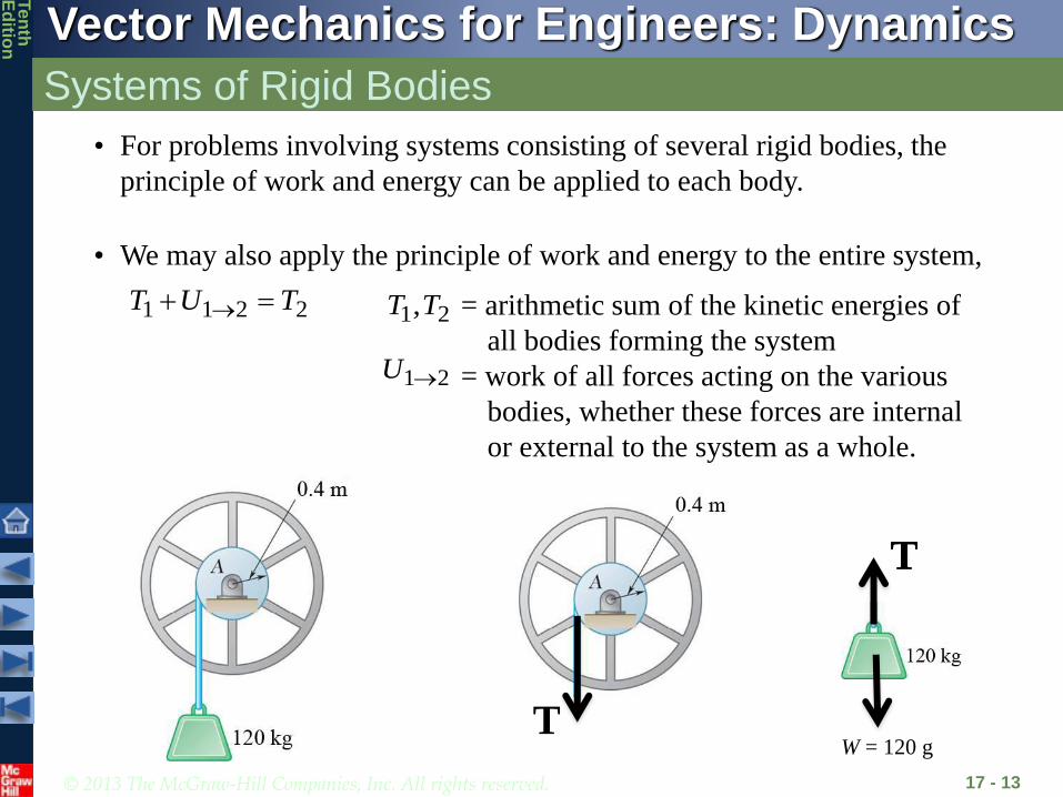
• For problems involving systems consisting of several rigid bodies, the
principle of work and energy can be applied to each body.
• We may also apply the principle of work and energy to the entire system,
2211 TUT = arithmetic sum of the kinetic energies of
all bodies forming the system
= work of all forces acting on the various
bodies, whether these forces are internal
or external to the system as a whole.
21,TT
21U
T
TT
W = 120 g

© 2013 The McGraw-Hill Companies, Inc. All rights reserved.
Vector Mechanics for Engineers: Dynamics
Ten
thE
ditio
n
Systems of Rigid Bodies
17 - 14
• For problems involving pin connected members, blocks and pulleys
connected by inextensible cords, and meshed gears,
- internal forces occur in pairs of equal and opposite forces
- points of application of each pair move through equal distances
- net work of the internal forces is zero
- work on the system reduces to the work of the external forces

© 2013 The McGraw-Hill Companies, Inc. All rights reserved.
Vector Mechanics for Engineers: Dynamics
Ten
thE
ditio
n
Conservation of Energy
17 - 15
• Expressing the work of conservative forces as a
change in potential energy, the principle of work
and energy becomes
2211 VTVT
sin3
sin2
1
32
10 2
22211
l
g
mglml
VTVT
0,0 11 VT
22
22121
212
21
21
222
1222
12
32
1
mlmllm
IvmT
sinsin21
21
2 mglWlV
• Consider the slender rod of mass m.
• mass m
• released with zero velocity
• determine at

© 2013 The McGraw-Hill Companies, Inc. All rights reserved.
Vector Mechanics for Engineers: Dynamics
Ten
thE
ditio
n
Power
17 - 16
• Power = rate at which work is done
• For a body acted upon by force and moving with velocity ,F
v
vFdt
dU Power
• For a rigid body rotating with an angular velocity and acted
upon by a couple of moment parallel to the axis of rotation,
M
Mdt
dM
dt
dUPower
© 2013 The McGraw-Hill Companies, Inc. All rights reserved.
Vector Mechanics for Engineers: Dynamics
Ten
thE
ditio
n
Sample Problem 17.1
17 - 17
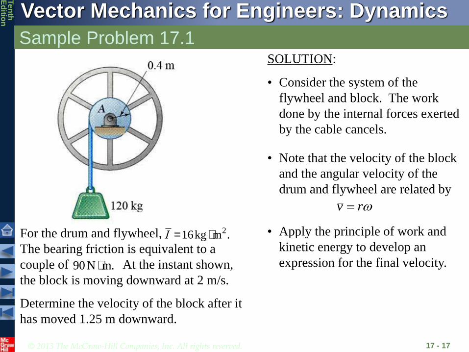
For the drum and flywheel,
The bearing friction is equivalent to a
couple of At the instant shown,
the block is moving downward at 2 m/s.
I =16kg × m2.
90N × m.
Determine the velocity of the block after it
has moved 1.25 m downward.
SOLUTION:
• Consider the system of the
flywheel and block. The work
done by the internal forces exerted
by the cable cancels.
• Apply the principle of work and
kinetic energy to develop an
expression for the final velocity.
• Note that the velocity of the block
and the angular velocity of the
drum and flywheel are related by
rv

© 2013 The McGraw-Hill Companies, Inc. All rights reserved.
Vector Mechanics for Engineers: Dynamics
Ten
thE
ditio
n
Sample Problem 17.1
17 - 18
SOLUTION:
• Consider the system of the flywheel and block. The work
done by the internal forces exerted by the cable cancels.
• Note that the velocity of the block and the angular velocity of
the drum and flywheel are related by
1 2 21 2
2m s5rad s
0.4m 0.4mw w w= = = = = =
v v vv r
r r
• Apply the principle of work and kinetic energy to develop an
expression for the final velocity.
( )( ) ( )( )
2 21 11 1 12 2
2 221 1120kg 2m s 16kg m 5rad s
2 2
440J
w= +
= + ×
=
T mv I
T2
= 12mv
2
2 + 12Iw
2
2
=1
2(120)v
2
2 +1
2(16)
v2
0.4
æ
èç
ö
ø÷
2
=110v2
2

© 2013 The McGraw-Hill Companies, Inc. All rights reserved.
Vector Mechanics for Engineers: Dynamics
Ten
thE
ditio
n
Sample Problem 17.1
17 - 19
2 21 11 1 12 2
440Jw= + =T mv I
2 2 21 12 2 2 22 2
110w= + =T mv I v
• Note that the block displacement and pulley
rotation are related by
22
1.25m3.125rad
0.4m= = =
s
rq
• Principle of work and energy:
1 1 2 2
22
2
440J 1190J 110
3.85m s
®+ =
+ =
=
T U T
v
v 2 3.85m s=v
( ) ( )
( )( ) ( )( )
1 2 2 1 2 1
2120kg 9.81m/s (1.2m) 90 N m 3.125rad
1190J
U W s s M q q® = - - -
= - ×
=
Then,
© 2013 The McGraw-Hill Companies, Inc. All rights reserved.
Vector Mechanics for Engineers: Dynamics
Ten
thE
ditio
n
Sample Problem 17.2
17 - 20
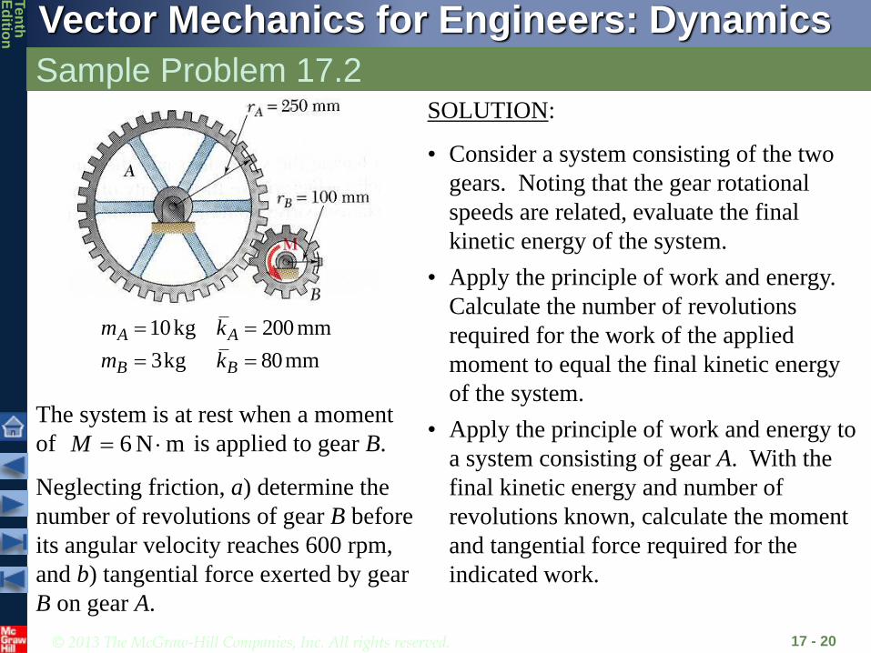
mm80kg3
mm200kg10
BB
AA
km
km
The system is at rest when a moment
of is applied to gear B.
Neglecting friction, a) determine the
number of revolutions of gear B before
its angular velocity reaches 600 rpm,
and b) tangential force exerted by gear
B on gear A.
mN6 M
SOLUTION:
• Consider a system consisting of the two
gears. Noting that the gear rotational
speeds are related, evaluate the final
kinetic energy of the system.
• Apply the principle of work and energy.
Calculate the number of revolutions
required for the work of the applied
moment to equal the final kinetic energy
of the system.
• Apply the principle of work and energy to
a system consisting of gear A. With the
final kinetic energy and number of
revolutions known, calculate the moment
and tangential force required for the
indicated work.

© 2013 The McGraw-Hill Companies, Inc. All rights reserved.
Vector Mechanics for Engineers: Dynamics
Ten
thE
ditio
n
Sample Problem 17.2
17 - 21
SOLUTION:
• Consider a system consisting of the two gears. Noting
that the gear rotational speeds are related, evaluate the
final kinetic energy of the system.
srad1.25250.0
100.08.62
srad8.62mins60
revrad2rpm600
A
BBA
B
r
r
222
222
mkg0192.0m080.0kg3
mkg400.0m200.0kg10
BBB
AAA
kmI
kmI
J9.163
8.620192.01.25400.02
212
21
2
212
21
2
BBAA IIT

© 2013 The McGraw-Hill Companies, Inc. All rights reserved.
Vector Mechanics for Engineers: Dynamics
Ten
thE
ditio
n
Sample Problem 17.2
17 - 22
• Apply the principle of work and energy. Calculate
the number of revolutions required for the work.
rad32.27
163.9JJ60
2211
B
B
TUT
rev35.42
32.27
B
• Apply the principle of work and energy to a system
consisting of gear A. Calculate the moment and
tangential force required for the indicated work.
J0.1261.25400.02
212
21
2 AAIT
mN52.11
J0.261rad10.930
2211
FrM
M
TUT
AA
A
rad93.10250.0
100.032.27
A
BBA
r
r
N2.46250.0
52.11F
© 2013 The McGraw-Hill Companies, Inc. All rights reserved.
Vector Mechanics for Engineers: Dynamics
Ten
thE
ditio
n
Sample Problem 17.3
17 - 23
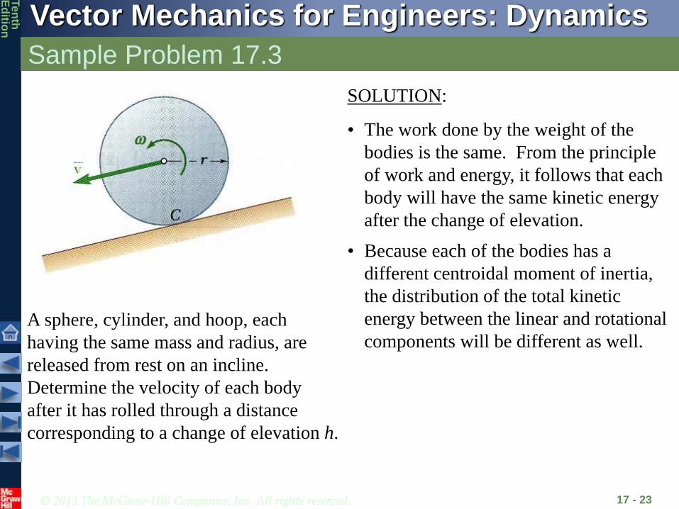
A sphere, cylinder, and hoop, each
having the same mass and radius, are
released from rest on an incline.
Determine the velocity of each body
after it has rolled through a distance
corresponding to a change of elevation h.
SOLUTION:
• The work done by the weight of the
bodies is the same. From the principle
of work and energy, it follows that each
body will have the same kinetic energy
after the change of elevation.
• Because each of the bodies has a
different centroidal moment of inertia,
the distribution of the total kinetic
energy between the linear and rotational
components will be different as well.

© 2013 The McGraw-Hill Companies, Inc. All rights reserved.
Vector Mechanics for Engineers: Dynamics
Ten
thE
ditio
n
Sample Problem 17.3
17 - 24
SOLUTION:
• The work done by the weight of the bodies is the
same. From the principle of work and energy, it
follows that each body will have the same kinetic
energy after the change of elevation.
r
vWith
2
221
2
212
212
212
21
2
vr
Im
r
vIvmIvmT
22
2
2
221
2211
1
22
0
mrI
gh
rIm
Whv
vr
ImWh
TUT

© 2013 The McGraw-Hill Companies, Inc. All rights reserved.
Vector Mechanics for Engineers: Dynamics
Ten
thE
ditio
n
Sample Problem 17.3
17 - 25
2
2
1
2
mrI
ghv
ghvmrIHoop
ghvmrICylinder
ghvmrISphere
2707.0:
2816.0:
2845.0:
2
2
21
2
52
• Because each of the bodies has a different
centroidal moment of inertia, the distribution of the
total kinetic energy between the linear and
rotational components will be different as well.
• The velocity of the body is independent of its mass
and radius.
NOTE:
• For a frictionless block sliding through the same
distance, ghv 2,0
• The velocity of the body does depend on
2
2
2 rk
mrI

© 2013 The McGraw-Hill Companies, Inc. All rights reserved.
Vector Mechanics for Engineers: Dynamics
Ten
thE
ditio
n
Sample Problem 17.4
17 - 26
A 15-kg slender rod pivots about the
point O. The other end is pressed
against a spring (k = 300 kN/m) until
the spring is compressed 40 mm and
the rod is in a horizontal position.
If the rod is released from this position,
determine its angular velocity and the
reaction at the pivot as the rod passes
through a vertical position.
SOLUTION:
• The weight and spring forces are
conservative. The principle of work and
energy can be expressed as
2211 VTVT
• Evaluate the initial and final potential
energy.
• Express the final kinetic energy in terms
of the final angular velocity of the rod.
• Based on the free-body-diagram
equation, solve for the reactions at the
pivot.
© 2013 The McGraw-Hill Companies, Inc. All rights reserved.
Vector Mechanics for Engineers: Dynamics
Ten
thE
ditio
n
Sample Problem 17.4
17 - 27
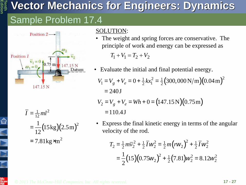
SOLUTION:
• The weight and spring forces are conservative. The
principle of work and energy can be expressed as
2211 VTVT
• Evaluate the initial and final potential energy.
( )( )221 11 12 2
0 300,000 N m 0.04m
240J
= + = + =
=
g eV V V kx
( )( )2 0 147.15N 0.75m
110.4J
= + = + =
=
g eV V V Wh
• Express the final kinetic energy in terms of the angular
velocity of the rod.( )( )
2112
2
2
115kg 2.5m
12
7.81kg m
=
=
= ×
I ml
( )
( )( ) ( )
22 2 21 1 1 12 2 2 2 22 2 2 2
2 2 212 2 22
115 0.75 7.81 8.12
2
w w w
w w w
= + = +
= + =
T mv I m r I

© 2013 The McGraw-Hill Companies, Inc. All rights reserved.
Vector Mechanics for Engineers: Dynamics
Ten
thE
ditio
n
Sample Problem 17.4
17 - 28
1 1 2 2
220 240J 8.12 110.4J
T V T V
w
+ = +
+ = +
From the principle of work and energy,
• Based on the free-body-diagram equation, solve for the
reactions at the pivot.
( )( )22 22 0.75m 3.995rad s 11.97m sw
a
= = =
=
n
t
a r
a r
an
=11.97m s2
at= ra
effOO MM rrmI 0 0
effxx FF rmRx 0xR
effyy FF
( )( )2
147.15N
15kg 11.97m s
32.4 N
- = -
= -
= -
y n
y
R ma
R
R = 32.4N
2 3.995rad sw =

© 2013 The McGraw-Hill Companies, Inc. All rights reserved.
Vector Mechanics for Engineers: Dynamics
Ten
thE
ditio
n
Sample Problem 17.5
17 - 29
Each of the two slender rods has a
mass of 6 kg. The system is released
from rest with b = 60o.
Determine a) the angular velocity of
rod AB when b = 20o, and b) the
velocity of the point D at the same
instant.
SOLUTION:
• Consider a system consisting of the two
rods. With the conservative weight force,
2211 VTVT
• Express the final kinetic energy of the
system in terms of the angular velocities of
the rods.
• Evaluate the initial and final potential
energy.
• Solve the energy equation for the angular
velocity, then evaluate the velocity of the
point D.

© 2013 The McGraw-Hill Companies, Inc. All rights reserved.
Vector Mechanics for Engineers: Dynamics
Ten
thE
ditio
n
Sample Problem 17.5
17 - 30
• Evaluate the initial and final potential energy.
J26.38
m325.0N86.5822 11
WyV
J10.15
m1283.0N86.5822 22
WyV
SOLUTION:
• Consider a system consisting of the two rods. With
the conservative weight force,
2211 VTVT
N86.58
sm81.9kg6 2
mgW

© 2013 The McGraw-Hill Companies, Inc. All rights reserved.
Vector Mechanics for Engineers: Dynamics
Ten
thE
ditio
n
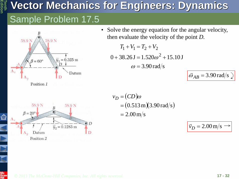
Sample Problem 17.5
17 - 31
Since is perpendicular to AB and is horizontal,
the instantaneous center of rotation for rod BD is C.
m75.0BC m513.020sinm75.02 CD
and applying the law of cosines to CDE, EC = 0.522 m
Bv
Dv
• Express the final kinetic energy of the system in terms
of the angular velocities of the rods.
0.375mABv
ABB BCABv BD
Consider the velocity of point B
m522.0BDv
22
1212
121 mkg281.0m75.0kg6 mlII BDAB
For the final kinetic energy,
2
2
212
1212
212
121
2
212
1212
212
121
2
520.1
281.0522.06281.0375.06
BDBDBDABABAB IvmIvmT
© 2013 The McGraw-Hill Companies, Inc. All rights reserved.
Vector Mechanics for Engineers: Dynamics
Ten
thE
ditio
n
Sample Problem 17.5
17 - 32
srad3.90
J10.151.520J26.380 2
2211
VTVT
• Solve the energy equation for the angular velocity,
then evaluate the velocity of the point D.
srad90.3AB
sm00.2
srad90.3m513.0
CDvD
sm00.2Dv
© 2013 The McGraw-Hill Companies, Inc. All rights reserved.
Vector Mechanics for Engineers: Dynamics
Ten
thE
ditio
n
Team Problem Solving
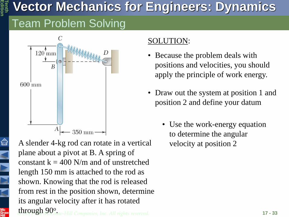
17 - 33
A slender 4-kg rod can rotate in a vertical
plane about a pivot at B. A spring of
constant k = 400 N/m and of unstretched
length 150 mm is attached to the rod as
shown. Knowing that the rod is released
from rest in the position shown, determine
its angular velocity after it has rotated
through 90o.
SOLUTION:
• Because the problem deals with
positions and velocities, you should
apply the principle of work energy.
• Draw out the system at position 1 and
position 2 and define your datum
• Use the work-energy equation
to determine the angular
velocity at position 2
© 2013 The McGraw-Hill Companies, Inc. All rights reserved.
Vector Mechanics for Engineers: Dynamics
Ten
thE
ditio
n
17 - 34
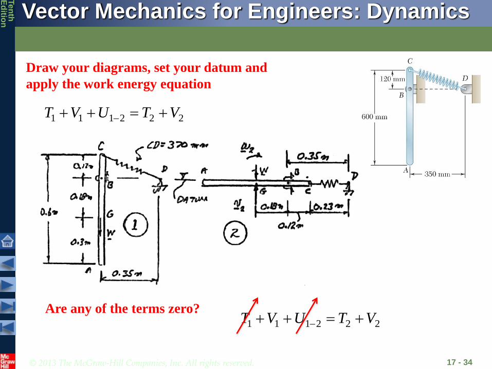
Draw your diagrams, set your datum and
apply the work energy equation
1 1 1 2 2 2T V U T V
Are any of the terms zero?1 1 1 2 2 2T V U T V

© 2013 The McGraw-Hill Companies, Inc. All rights reserved.
Vector Mechanics for Engineers: Dynamics
Ten
thE
ditio
n
Team Problem Solving
17 - 35
Determine the spring energy at position 1
x1=CD- (150 mm
Unstretched Length
) = 370-150 = 220 mm = 0.22 m
Ve
=1
2kx
1
2 =1
2(400 N/m)(0.22 m)2 = 9.68 J
21 (4 kg)(9.81 m/s )( 0.22 m) 7.063 JgV Wh mgh
Determine the potential energy due to
gravity at position 1
Determine the spring energy at position 2
2
2 22 2
230 mm 150 mm 80 mm 0.08 m
1 1(400 N/m)(0.08 m) 1.28 J
2 2e
x
V kx
Determine the potential energy due to
gravity at position 22 0gV
© 2013 The McGraw-Hill Companies, Inc. All rights reserved.
Vector Mechanics for Engineers: Dynamics
Ten
thE
ditio
n
Team Problem Solving
17 - 36
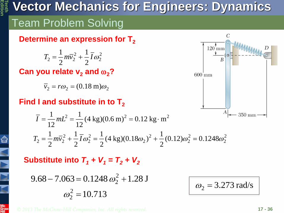
2 22 2 2
1 1
2 2T mv I
2 2 2(0.18 m)v r
Determine an expression for T2
Can you relate v2 and 2?
2 2 2
2 2 2 2 22 2 2 2 2 2
1 1(4 kg)(0.6 m) 0.12 kg m
12 12
1 1 1 1(4 kg)(0.18 ) (0.12) 0.1248
2 2 2 2
I mL
T mv I
Find I and substitute in to T2
22
22
9.68 7.063 0.1248 1.28 J
10.713
2 3.273 rad/s
Substitute into T1 + V1 = T2 + V2

© 2013 The McGraw-Hill Companies, Inc. All rights reserved.
Vector Mechanics for Engineers: Dynamics
Ten
thE
ditio
n
Concept Question
17 - 37
For the previous problem, how would
you determine the reaction forces at B
when the bar is horizontal?
a) Apply linear-momentum to solve for BxDt and ByDt
b) Use work-energy to determine the work done by the
moment at C
c) Use sum of forces and sum of moments equations when
the bar is horizontal
© 2013 The McGraw-Hill Companies, Inc. All rights reserved.
Vector Mechanics for Engineers: Dynamics
Ten
thE
ditio
n
Angular Impulse Momentum
17 - 38
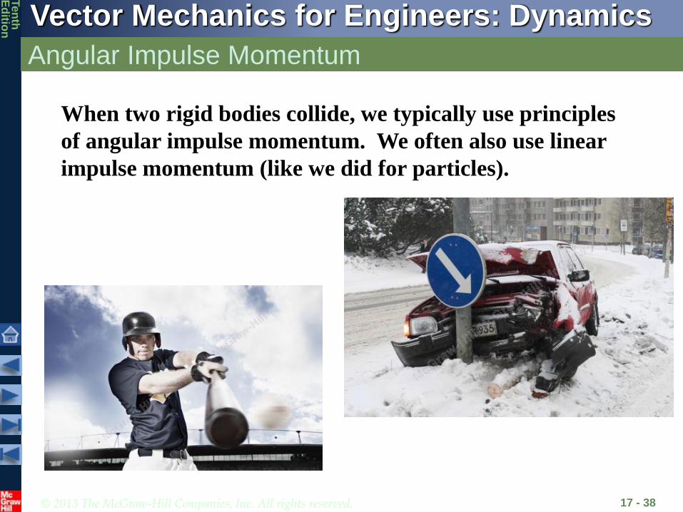
When two rigid bodies collide, we typically use principles
of angular impulse momentum. We often also use linear
impulse momentum (like we did for particles).

© 2013 The McGraw-Hill Companies, Inc. All rights reserved.
Vector Mechanics for Engineers: Dynamics
Ten
thE
ditio
n
Introduction
17 - 39
Forces and
Accelerations
Velocities and
Displacements
Velocities and
Time
Approaches to Rigid Body Kinetics Problems
Newton’s Second
Law (last chapter)
Work-Energy Impulse-
Momentum
2211 TUT
Få =maG
MGå = H
G
mv1+ F dt
t1
t2
ò =mv2
2
11 2
t
G G Gt
I M dt I

© 2013 The McGraw-Hill Companies, Inc. All rights reserved.
Vector Mechanics for Engineers: Dynamics
Ten
thE
ditio
n
Principle of Impulse and Momentum
17 - 40
• Method of impulse and momentum:
- well suited to the solution of problems involving time and velocity
- the only practicable method for problems involving impulsive
motion and impact.
Sys Momenta1 + Sys Ext Imp1-2 = Sys Momenta2
© 2013 The McGraw-Hill Companies, Inc. All rights reserved.
Vector Mechanics for Engineers: Dynamics
Ten
thE
ditio
n
Principle of Impulse and Momentum
17 - 41
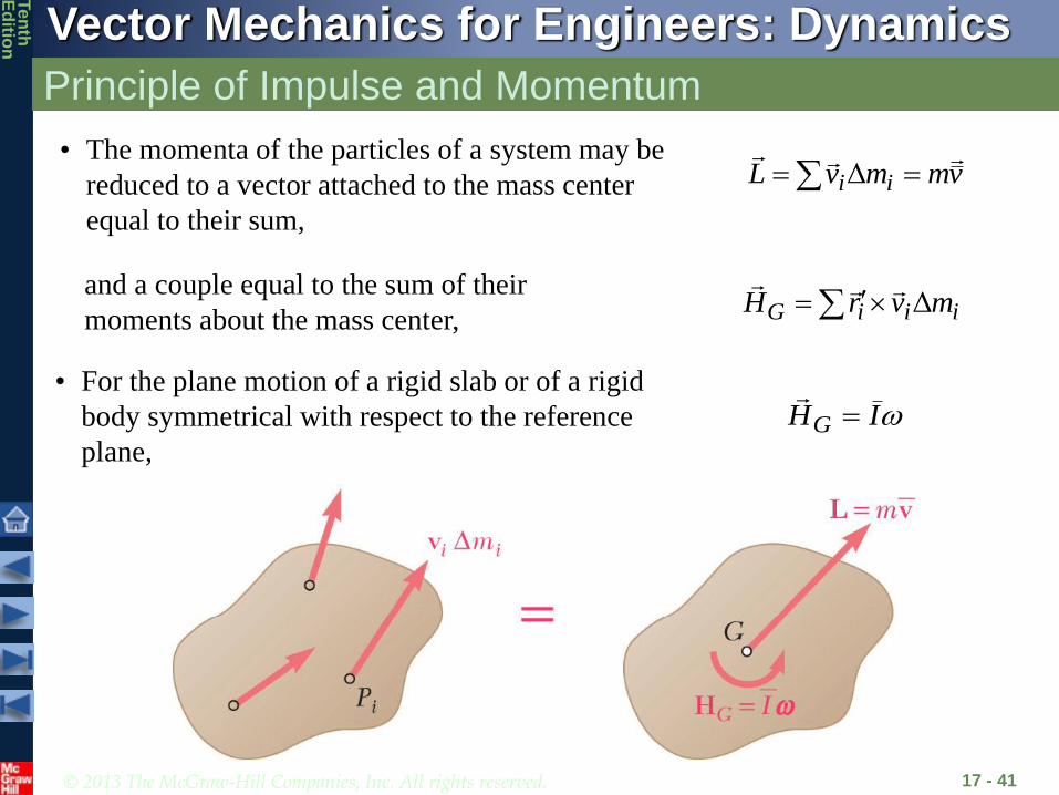
vmmvL ii
Δ
• The momenta of the particles of a system may be
reduced to a vector attached to the mass center
equal to their sum,
iiiG mvrH Δ
and a couple equal to the sum of their
moments about the mass center,
IHG • For the plane motion of a rigid slab or of a rigid
body symmetrical with respect to the reference
plane,

© 2013 The McGraw-Hill Companies, Inc. All rights reserved.
Vector Mechanics for Engineers: Dynamics
Ten
thE
ditio
n
Principle of Impulse and Momentum
17 - 42
• For plane motion problems, draw out an impulse-momentum diagram,
(similar to a free-body diagram)
• This leads to three equations of motion:
- summing and equating momenta and impulses in the x and y
directions
- summing and equating the moments of the momenta and impulses
with respect to any given point (often choose G)
© 2013 The McGraw-Hill Companies, Inc. All rights reserved.
Vector Mechanics for Engineers: Dynamics
Ten
thE
ditio
n
Impulse Momentum Diagrams
17 - 43
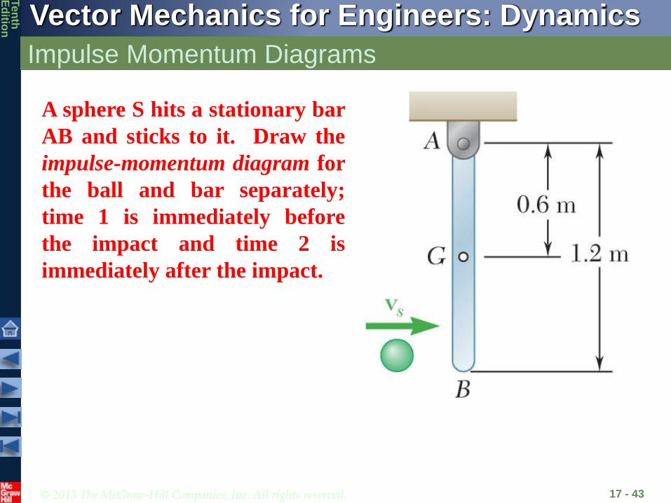
A sphere S hits a stationary bar
AB and sticks to it. Draw the
impulse-momentum diagram for
the ball and bar separately;
time 1 is immediately before
the impact and time 2 is
immediately after the impact.
© 2013 The McGraw-Hill Companies, Inc. All rights reserved.
Vector Mechanics for Engineers: Dynamics
Ten
thE
ditio
n
Impulse Momentum Diagrams
17 - 44
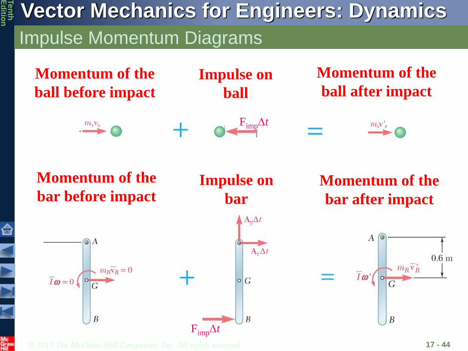
FimpDt
Momentum of the
ball before impact
Impulse on
ball
Momentum of the
ball after impact
FimpDt
Momentum of the
bar before impactImpulse on
bar
Momentum of the
bar after impact

© 2013 The McGraw-Hill Companies, Inc. All rights reserved.
Vector Mechanics for Engineers: Dynamics
Ten
thE
ditio
n
Principle of Impulse and Momentum
17 - 45
• Fixed axis rotation:
- The angular momentum about O
2rmI
rrmI
rvmIIO
- Equating the moments of the momenta and
impulses about O,
21
2
1
O
t
tOO IdtMI
The pin forces at point O now contribute no moment to the equation
© 2013 The McGraw-Hill Companies, Inc. All rights reserved.
Vector Mechanics for Engineers: Dynamics
Ten
thE
ditio
n
Systems of Rigid Bodies
17 - 46
• Motion of several rigid bodies can be analyzed by applying
the principle of impulse and momentum to each body
separately.
• For problems involving no more than three unknowns, it may
be convenient to apply the principle of impulse and
momentum to the system as a whole.
• For each moving part of the system, the diagrams of momenta
should include a momentum vector and/or a momentum couple.
• Internal forces occur in equal and opposite pairs of vectors and
generate impulses that cancel out.

© 2013 The McGraw-Hill Companies, Inc. All rights reserved.
Vector Mechanics for Engineers: Dynamics
Ten
thE
ditio
n
Practice
17 - 47
FimpDt
From the previous problem, notice that the impulse acting on the
sphere is equal and opposite to the impulse acting on the bar. We can
take advantage of this by drawing the impulse-momentum diagram of
the entire system, as shown on the next slide.
FimpDt

© 2013 The McGraw-Hill Companies, Inc. All rights reserved.
Vector Mechanics for Engineers: Dynamics
Ten
thE
ditio
n
Practice – Diagram for combined system
17 - 48
FimpDt
FimpDt
© 2013 The McGraw-Hill Companies, Inc. All rights reserved.
Vector Mechanics for Engineers: Dynamics
Ten
thE
ditio
n
Conservation of Angular Momentum
17 - 49
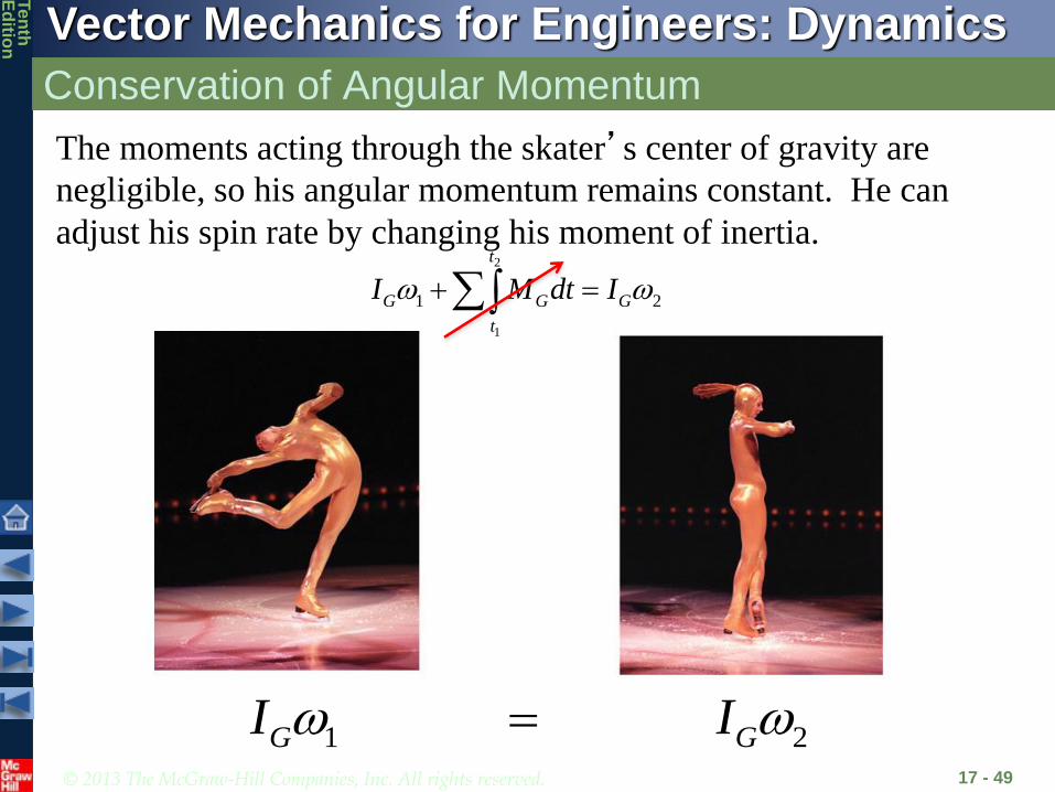
1 2 G GI I
The moments acting through the skater’s center of gravity are
negligible, so his angular momentum remains constant. He can
adjust his spin rate by changing his moment of inertia.2
1
1 2
t
G G G
t
I M dt I

© 2013 The McGraw-Hill Companies, Inc. All rights reserved.
Vector Mechanics for Engineers: Dynamics
Ten
thE
ditio
n
Conservation of Angular Momentum
17 - 50
• When the sum of the angular impulses pass through O, the
linear momentum may not be conserved, yet the angular
momentum about O is conserved,
2010 HH
• Two additional equations may be written by summing x and
y components of momenta and may be used to determine
two unknown linear impulses, such as the impulses of the
reaction components at a fixed point.
• When no external force acts on a rigid body or a system of rigid
bodies, the system of momenta at t1 is equipollent to the system
at t2. The total linear momentum and angular momentum about
any point are conserved,
2010 HH 21 LL

© 2013 The McGraw-Hill Companies, Inc. All rights reserved.
Vector Mechanics for Engineers: Dynamics
Ten
thE
ditio
n
Concept Question
17 - 51
For the problem we looked at previously, is the
angular momentum about G conserved?YES NO
YES NOFor the problem we looked at previously, is the
angular momentum about point A conserved?
For the problem we looked at previously, is the
linear momentum of the system conserved?YES NO

© 2013 The McGraw-Hill Companies, Inc. All rights reserved.
Vector Mechanics for Engineers: Dynamics
Ten
thE
ditio
n
Sample Problem 17.6
17 - 52
The system is at rest when a moment
of is applied to gear B.
Neglecting friction, a) determine the
time required for gear B to reach an
angular velocity of 600 rpm, and b) the
tangential force exerted by gear B on
gear A.
mN6 M
mm80kg3
mm200kg10
BB
AA
km
km
SOLUTION:
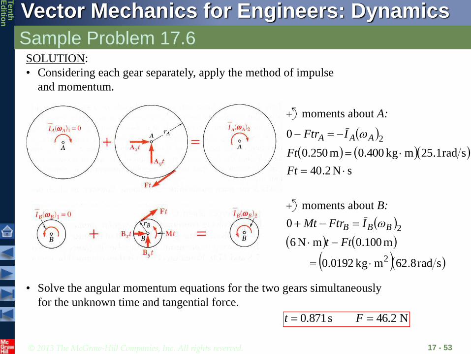
• Considering each gear separately, apply
the method of impulse and momentum.
• Solve the angular momentum equations
for the two gears simultaneously for the
unknown time and tangential force.
© 2013 The McGraw-Hill Companies, Inc. All rights reserved.
Vector Mechanics for Engineers: Dynamics
Ten
thE
ditio
n
Sample Problem 17.6
17 - 53
SOLUTION:
• Considering each gear separately, apply the method of impulse
and momentum.
sN2.40
srad1.25mkg400.0m250.0
0 2
Ft
Ft
IFtr AAA
moments about A:
moments about B:
srad8.62mkg0192.0
m100.0mN6
0
2
2
Ftt
IFtrMt BBB
• Solve the angular momentum equations for the two gears simultaneously
for the unknown time and tangential force.
N 46.2s 871.0 Ft

© 2013 The McGraw-Hill Companies, Inc. All rights reserved.
Vector Mechanics for Engineers: Dynamics
Ten
thE
ditio
n
Sample Problem 17.7
17 - 54
Uniform sphere of mass m and
radius r is projected along a rough
horizontal surface with a linear
velocity and no angular velocity.
The coefficient of kinetic friction is
Determine a) the time t2 at which
the sphere will start rolling without
sliding and b) the linear and angular
velocities of the sphere at time t2.
.k
1v
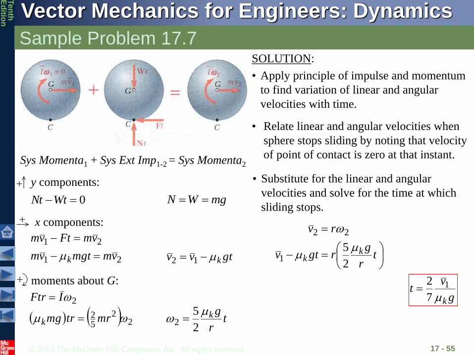
SOLUTION:
• Apply principle of impulse and momentum
to find variation of linear and angular
velocities with time.
• Relate the linear and angular velocities
when the sphere stops sliding by noting
that the velocity of the point of contact is
zero at that instant.
• Substitute for the linear and angular
velocities and solve for the time at which
sliding stops.
• Evaluate the linear and angular velocities
at that instant.
© 2013 The McGraw-Hill Companies, Inc. All rights reserved.
Vector Mechanics for Engineers: Dynamics
Ten
thE
ditio
n
Sample Problem 17.7
17 - 55
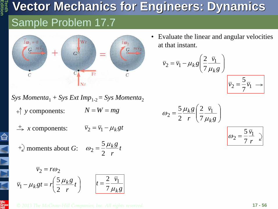
SOLUTION:
• Apply principle of impulse and momentum
to find variation of linear and angular
velocities with time.
0WtNt
y components:
x components:
21
21
vmmgtvm
vmFtvm
k
gtvv k 12
mgWN
moments about G:
22
52
2
mrtrmg
IFtr
k
tr
gk
2
52
Sys Momenta1 + Sys Ext Imp1-2 = Sys Momenta2
• Relate linear and angular velocities when
sphere stops sliding by noting that velocity
of point of contact is zero at that instant.
tr
grgtv
rv
kk
2
51
22
• Substitute for the linear and angular
velocities and solve for the time at which
sliding stops.
g
vt
k1
7
2
© 2013 The McGraw-Hill Companies, Inc. All rights reserved.
Vector Mechanics for Engineers: Dynamics
Ten
thE
ditio
n
Sample Problem 17.7
17 - 56
x components: gtvv k 12
y components: mgWN
moments about G: tr
gk
2
52
Sys Momenta1 + Sys Ext Imp1-2 = Sys Momenta2
tr
grgtv
rv
kk
2
51
22
g
vt
k1
7
2
• Evaluate the linear and angular velocities
at that instant.
g
vgvv
kk
1
127
2
g
v
r
g
k
k
1
27
2
2
5
127
5vv
r
v12
7
5
© 2013 The McGraw-Hill Companies, Inc. All rights reserved.
Vector Mechanics for Engineers: Dynamics
Ten
thE
ditio
n
Sample Problem 17.8
17 - 57
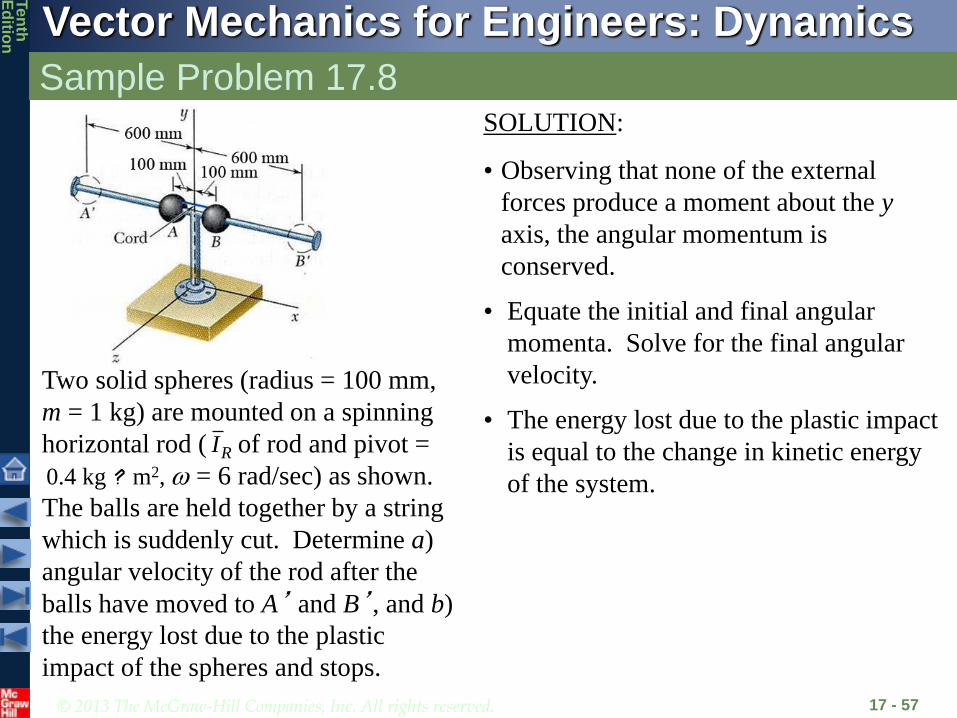
Two solid spheres (radius = 100 mm,
m = 1 kg) are mounted on a spinning
horizontal rod ( of rod and pivot =
0.4 kg ? m2, = 6 rad/sec) as shown.
The balls are held together by a string
which is suddenly cut. Determine a)
angular velocity of the rod after the
balls have moved to A’ and B’, and b)
the energy lost due to the plastic
impact of the spheres and stops.
RI
SOLUTION:
• Observing that none of the external
forces produce a moment about the y
axis, the angular momentum is
conserved.
• Equate the initial and final angular
momenta. Solve for the final angular
velocity.
• The energy lost due to the plastic impact
is equal to the change in kinetic energy
of the system.

© 2013 The McGraw-Hill Companies, Inc. All rights reserved.
Vector Mechanics for Engineers: Dynamics
Ten
thE
ditio
n
Sample Problem 17.8
17 - 58
Sys Momenta1 + Sys Ext Imp1-2 = Sys Momenta2
2222211111 22 RSsRSs IIrrmIIrrm
SOLUTION:
• Observing that none of the
external forces produce a
moment about the y axis, the
angular momentum is
conserved.
• Equate the initial and final
angular momenta. Solve for
the final angular velocity.
( )( )22 22 25 5
1kg 0.1m 0.004kg m= = = ×SI ma
( )( ) ( )( )2 22 2 2 21 21kg 0.1m 0.01kg m 1kg 0.6m 0.36kg m= = × = = ×S Sm r m r
RSs
RSs
IIrm
IIrm
22
21
12
srad61 2sftlb 25.0 RI
2 2.28rad sw =
© 2013 The McGraw-Hill Companies, Inc. All rights reserved.
Vector Mechanics for Engineers: Dynamics
Ten
thE
ditio
n
Sample Problem 17.8
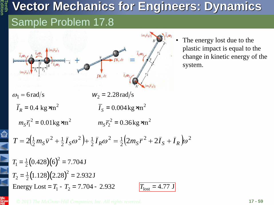
17 - 59
• The energy lost due to the
plastic impact is equal to the
change in kinetic energy of the
system.
20.004kg m= ×SI
2 21 0.01kg m= ×Sm r
srad61
20.4 kg m= ×RI
2 2.28rad sw =
2 22 0.36kg m= ×Sm r
22
212
212
212
21 222 RSSRSS IIrmIIvmT
( )( )
( )( )
211 2
212 2
1 2
0.428 6 7.704J
1.128 2.28 2.932J
Energy Lost 7.704 2.932
= =
= =
= - = -
T
T
T T lost 4.77 J=T

© 2013 The McGraw-Hill Companies, Inc. All rights reserved.
Vector Mechanics for Engineers: Dynamics
Ten
thE
ditio
n
Team Problem Solving
17 - 60
A projectile of mass 40 g is fired with a horizontal velocity of
150 m/s into the lower end of a slender 7.5-kg bar of length
L= 0.75 m. Knowing that h = 0.3 m and that the bar is
initially at rest, determine the angular velocity of the bar
when it reaches the horizontal position.
SOLUTION:
• Consider the projectile and bar as a
single system. Apply the principle of
impulse and momentum.
• The moments about C of the momenta
and impulses provide a relation between
the final angular velocity of the rod and
velocity of the projectile.
• Use the principle of work-energy to
determine the angle through which the
bar swings.

© 2013 The McGraw-Hill Companies, Inc. All rights reserved.
Vector Mechanics for Engineers: Dynamics
Ten
thE
ditio
n
Team Problem Solving
17 - 61
Given: mo= 0.04 kg, vo= 150 m/s
mAB = 7.5 kg L= 0.75 m h = 0.3 m
Find: AB when = 90o
Draw the impulse momentum diagram
Apply the angular impulse momentum
equation about point C
0 0 0( ) ( )B Cm v L h m v L h I
0 0 0 0( ) ( )2
B
Lm v L h m v L h mv h I
Or you could use the relationship:
© 2013 The McGraw-Hill Companies, Inc. All rights reserved.
Vector Mechanics for Engineers: Dynamics
Ten
thE
ditio
n
Team Problem Solving
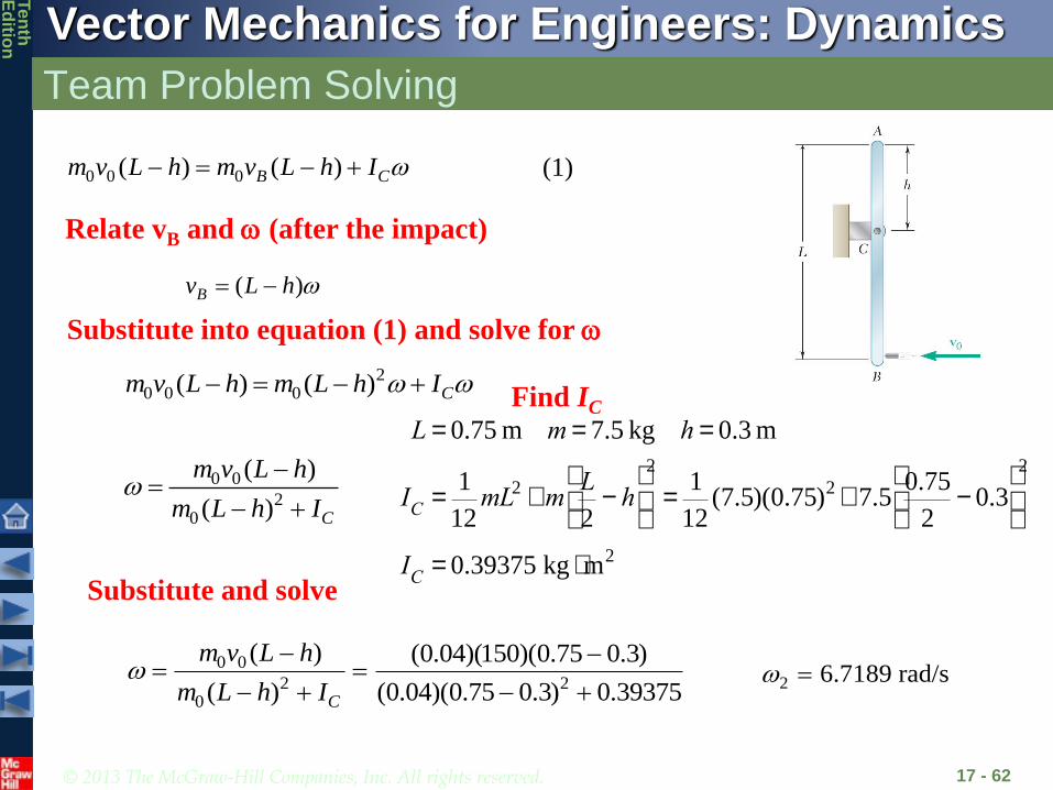
17 - 62
Relate vB and (after the impact)
0 0 0( ) ( )B Cm v L h m v L h I
( )Bv L h
Substitute into equation (1) and solve for
20 0 0( ) ( ) Cm v L h m L h I
0 0
20
( )
( ) C
m v L h
m L h I
0 0
2 20
( ) (0.04)(150)(0.75 0.3)
( ) (0.04)(0.75 0.3) 0.39375C
m v L h
m L h I
L = 0.75 m m = 7.5 kg h = 0.3 m
IC
=1
12mL2 +m
L
2- h
æ
èç
ö
ø÷
2
=1
12(7.5)(0.75)2 + 7.5
0.75
2- 0.3
æ
èç
ö
ø÷
2
IC
= 0.39375 kg × m2
2 6.7189 rad/s
Find IC
Substitute and solve
(1)
© 2013 The McGraw-Hill Companies, Inc. All rights reserved.
Vector Mechanics for Engineers: Dynamics
Ten
thE
ditio
n
Team Problem Solving
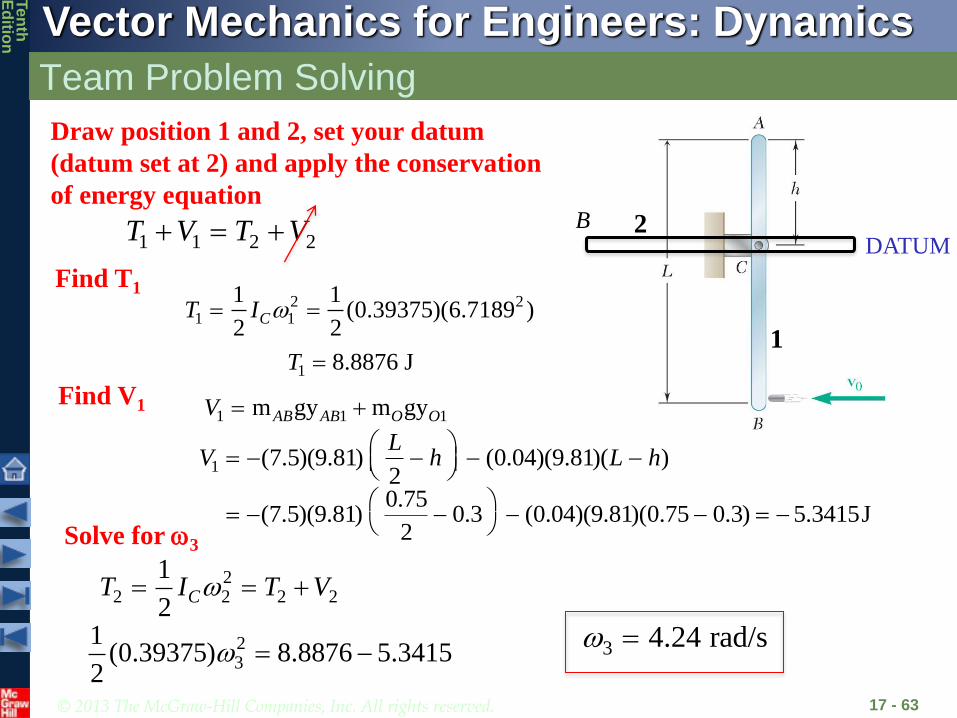
17 - 63
Draw position 1 and 2, set your datum
(datum set at 2) and apply the conservation
of energy equation
1 1 2 2T V T V DATUM
2 21 1
1 1(0.39375)(6.7189 )
2 2CT I
1 8.8876 JT
1 1 1m gy m gyAB AB O OV
Find T1
Find V1
B
Solve for 3
22 2 2 2
1
2CT I T V
23
1(0.39375) 8.8876 5.3415
2 3 4.24 rad/s
1
2
1 (7.5)(9.81) (0.04)(9.81)( )2
LV h L h
0.75(7.5)(9.81) 0.3 (0.04)(9.81)(0.75 0.3) 5.3415J
2

© 2013 The McGraw-Hill Companies, Inc. All rights reserved.
Vector Mechanics for Engineers: Dynamics
Ten
thE
ditio
n
Concept Question
17 - 64
For the previous problem, how would
you determine the reaction forces at C
when the bar is horizontal?
a) Apply linear-momentum to solve for CxDt and CyDt
b) Use work-energy to determine the work done by the
moment at C
c) Use sum of forces and sum of moments equations when
the bar is horizontal

© 2013 The McGraw-Hill Companies, Inc. All rights reserved.
Vector Mechanics for Engineers: Dynamics
Ten
thE
ditio
n
Concept Question
17 - 65
For the previous problem, what would
happen if the coefficient of restitution
between the projectile and bar was 1.0
instead of zero?
a) The angular velocity after impact would be bigger
b) The angular velocity after impact would be smaller
c) The angular velocity after impact would be the same
d) Not enough information to tell

© 2013 The McGraw-Hill Companies, Inc. All rights reserved.
Vector Mechanics for Engineers: Dynamics
Ten
thE
ditio
n
Eccentric Impact
17 - 66
Period of deformation Period of restitution
dtRImpulse
dtPImpulse
nBnA uu
• Principle of impulse and momentum is supplemented by
nBnA
nAnB
vv
vv
dtP
dtRnrestitutiooftcoefficiene
These velocities are for the
points of impact

© 2013 The McGraw-Hill Companies, Inc. All rights reserved.
Vector Mechanics for Engineers: Dynamics
Ten
thE
ditio
n
Concept Questions
17 - 67
The cars collide, hitting at point
P as shown. Which of the
following can you use to help
analyze the collision?
a) The linear momentum of car A is
conserved.
b) The linear momentum of the
combined two cars is conserved
c) The total kinetic energy before the
impact equals the total kinetic
energy after the impact
d) The angular momentum about the
CG of car B is conserved
P
P
A
B
© 2013 The McGraw-Hill Companies, Inc. All rights reserved.
Vector Mechanics for Engineers: Dynamics
Ten
thE
ditio
n
Sample Problem 17.9
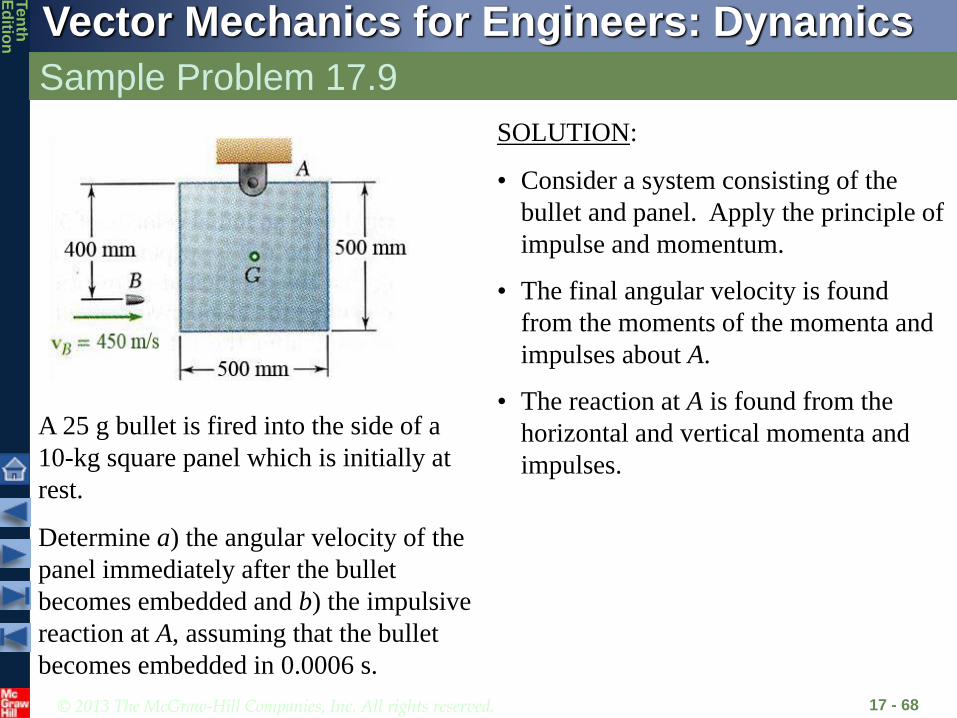
17 - 68
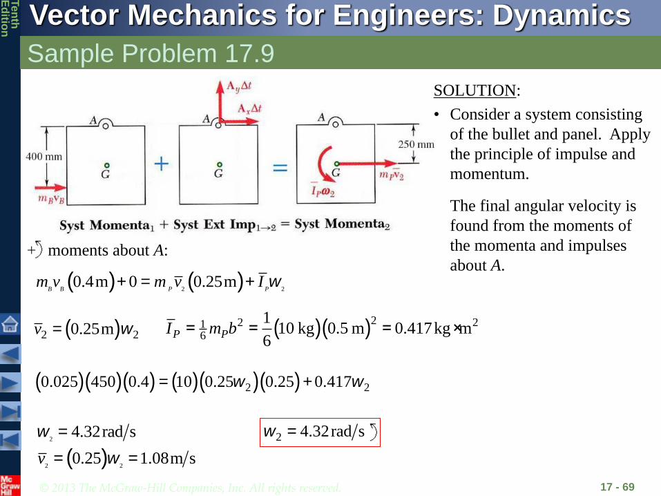
A 25 g bullet is fired into the side of a
10-kg square panel which is initially at
rest.
Determine a) the angular velocity of the
panel immediately after the bullet
becomes embedded and b) the impulsive
reaction at A, assuming that the bullet
becomes embedded in 0.0006 s.
SOLUTION:
• Consider a system consisting of the
bullet and panel. Apply the principle of
impulse and momentum.
• The final angular velocity is found
from the moments of the momenta and
impulses about A.
• The reaction at A is found from the
horizontal and vertical momenta and
impulses.
© 2013 The McGraw-Hill Companies, Inc. All rights reserved.
Vector Mechanics for Engineers: Dynamics
Ten
thE
ditio
n
Sample Problem 17.9
17 - 69
• The final angular velocity is
found from the moments of
the momenta and impulses
about A.moments about A:
( ) ( )2 2
0.4m 0 0.25m w+ = +B B P P
m v m v I
( )2 20.25mv w= ( )( )22 21
6
110 kg 0.5 m 0.417kg m
6P PI m b= = = ×
( )( )( ) ( )( )( )2 20.025 450 0.4 10 0.25 0.25 0.417w w= +
( )2
2 2
4.32rad s
0.25 1.08m s
w
w
=
= =v
2 4.32rad sw =
SOLUTION:
• Consider a system consisting
of the bullet and panel. Apply
the principle of impulse and
momentum.

© 2013 The McGraw-Hill Companies, Inc. All rights reserved.
Vector Mechanics for Engineers: Dynamics
Ten
thE
ditio
n
Sample Problem 17.9
17 - 70
( )2 2 24.32rad s 0.25 1.08 m svw w= = =
• The reactions at A are found
from the horizontal and
vertical momenta and
impulses.
x components:
( )( ) ( ) ( )( )2
0.25 450 0.0006 10 1.08
B B x p
x
m v A t m v
A
+ D =
+ =
750 NxA = - 750 NxA =
y components:
00 tAyD 0yA

© 2013 The McGraw-Hill Companies, Inc. All rights reserved.
Vector Mechanics for Engineers: Dynamics
Ten
thE
ditio
n
Sample Problem 17.10
17 - 71
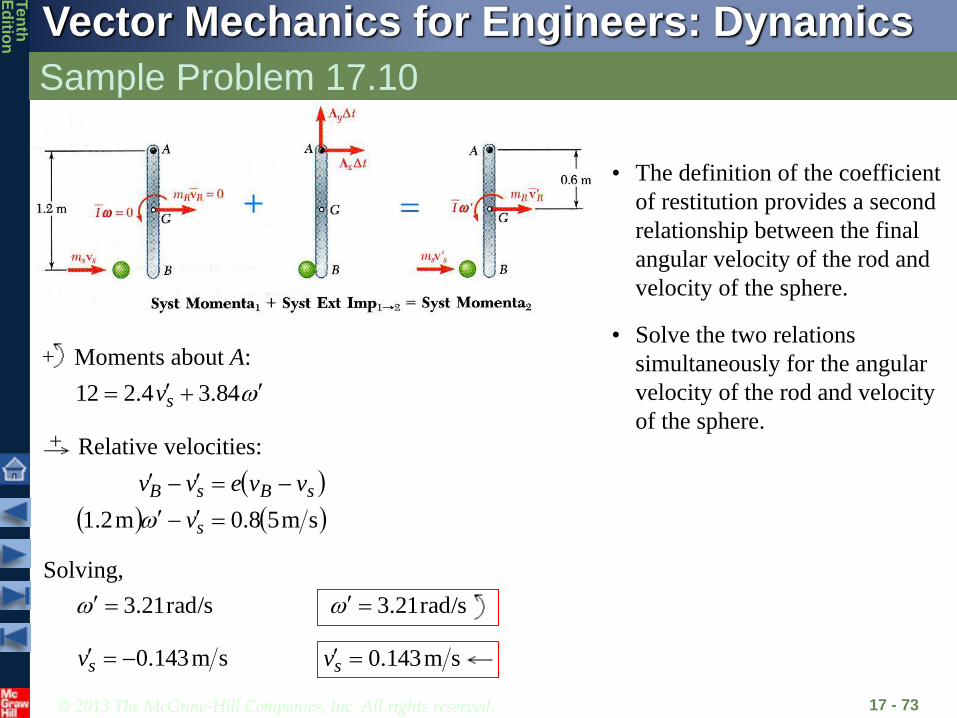
A 2-kg sphere with an initial velocity
of 5 m/s strikes the lower end of an 8-
kg rod AB. The rod is hinged at A and
initially at rest. The coefficient of
restitution between the rod and sphere
is 0.8.
Determine the angular velocity of the
rod and the velocity of the sphere
immediately after impact.
SOLUTION:
• Consider the sphere and rod as a single
system. Apply the principle of impulse
and momentum.
• The moments about A of the momenta
and impulses provide a relation between
the final angular velocity of the rod and
velocity of the sphere.
• The definition of the coefficient of
restitution provides a second
relationship between the final angular
velocity of the rod and velocity of the
sphere.
• Solve the two relations simultaneously
for the angular velocity of the rod and
velocity of the sphere.

© 2013 The McGraw-Hill Companies, Inc. All rights reserved.
Vector Mechanics for Engineers: Dynamics
Ten
thE
ditio
n
Sample Problem 17.10
17 - 72
SOLUTION:
• Consider the sphere and rod as a
single system. Apply the
principle of impulse and
momentum.
• The moments about A of the
momenta and impulses provide a
relation between the final
angular velocity of the rod and
velocity of the rod.
moments about A:
Ivmvmvm RRssss m6.0m2.1m2.1
22
1212
121 mkg96.0m2.1kg8
m6.0
mLI
rvR
2mkg96.0
m6.0m6.0kg8m2.1kg2m2.1sm5kg2 sv
84.34.212 sv
© 2013 The McGraw-Hill Companies, Inc. All rights reserved.
Vector Mechanics for Engineers: Dynamics
Ten
thE
ditio
n
Sample Problem 17.10
17 - 73
Moments about A:
84.34.212 sv
• The definition of the coefficient
of restitution provides a second
relationship between the final
angular velocity of the rod and
velocity of the sphere.
sm58.0m2.1
s
sBsB
v
vvevv
Relative velocities:
• Solve the two relations
simultaneously for the angular
velocity of the rod and velocity
of the sphere.
Solving,
sm143.0sv sm143.0sv
rad/s21.3 rad/s21.3

© 2013 The McGraw-Hill Companies, Inc. All rights reserved.
Vector Mechanics for Engineers: Dynamics
Ten
thE
ditio
n
Sample Problem 17.11
17 - 74
A square package of mass m moves
down conveyor belt A with constant
velocity. At the end of the conveyor,
the corner of the package strikes a rigid
support at B. The impact is perfectly
plastic.
Derive an expression for the minimum
velocity of conveyor belt A for which
the package will rotate about B and
reach conveyor belt C.
SOLUTION:
• Apply the principle of impulse and
momentum to relate the velocity of the
package on conveyor belt A before the
impact at B to the angular velocity about
B after impact.
• Apply the principle of conservation of
energy to determine the minimum initial
angular velocity such that the mass
center of the package will reach a
position directly above B.
• Relate the required angular velocity to
the velocity of conveyor belt A.

© 2013 The McGraw-Hill Companies, Inc. All rights reserved.
Vector Mechanics for Engineers: Dynamics
Ten
thE
ditio
n
Sample Problem 17.11
17 - 75
SOLUTION:
• Apply the principle of impulse and momentum to relate the velocity of the package on
conveyor belt A before the impact at B to angular velocity about B after impact.
Moments about B:
222
221
1 0 Iavmavm 2
61
222
2 amIav
22
61
22
222
21
1 0 amaamavm
234
1 av

© 2013 The McGraw-Hill Companies, Inc. All rights reserved.
Vector Mechanics for Engineers: Dynamics
Ten
thE
ditio
n
Sample Problem 17.11
17 - 76
• Apply the principle of conservation of energy to determine
the minimum initial angular velocity such that the mass
center of the package will reach a position directly above B.
3322 VTVT
22 WhV
22
2
312
22
61
21
2
222
21
222
1222
12
mamaam
ImvT
33 WhV
03 T (solving for the minimum 2)
aa
GBh
612.060sin
1545sin
22
2
aah 707.022
3
agaaa
ghh
ma
W
WhWhma
285.0612.0707.033
0
2232
22
3222
2
31
agaav 285.034
234
1 gav 712.01

© 2013 The McGraw-Hill Companies, Inc. All rights reserved.
Vector Mechanics for Engineers: Dynamics
Ten
thE
ditio
n
Team Problem Solving
17 - 77
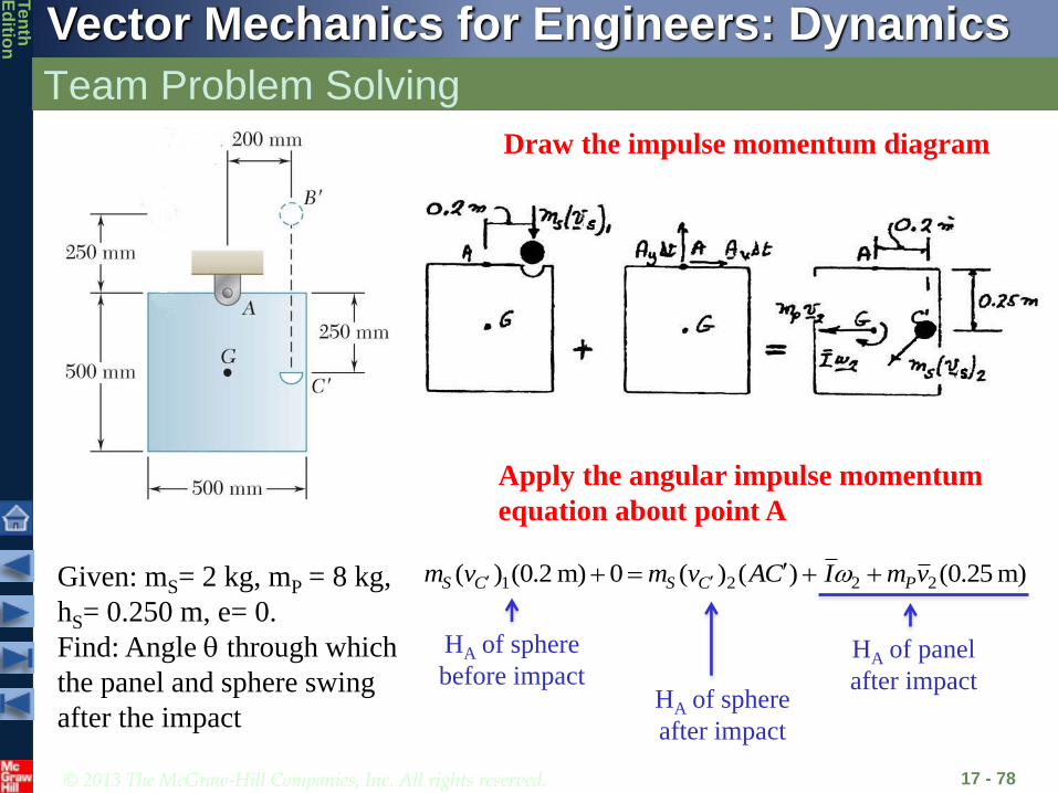
An 8-kg wooden panel P is suspended from a pin support at A and is
initially at rest. A 2-kg metal sphere S is released from rest at B and falls
into a hemispherical cup C attached to the panel at the same level as the
mass center G. Assuming that the impact is perfectly plastic, determine
the angular velocity of the panel immediately after the impact.
SOLUTION:
• Consider the sphere and panel as a
single system. Apply the principle of
impulse and momentum.
• The moments about A of the momenta
and impulses provide a relation between
the angular velocity of the panel and
velocity of the sphere.
• Use the principle of work-energy to
determine the angle through which the
panel swings.
© 2013 The McGraw-Hill Companies, Inc. All rights reserved.
Vector Mechanics for Engineers: Dynamics
Ten
thE
ditio
n
Team Problem Solving
17 - 78
Given: mS= 2 kg, mP = 8 kg,
hS= 0.250 m, e= 0.
Find: Angle through which
the panel and sphere swing
after the impact
Draw the impulse momentum diagram
Apply the angular impulse momentum
equation about point A
1 2 2 2( ) (0.2 m) 0 ( ) ( ) (0.25 m)S C S C Pm v m v AC I m v
HA of sphere
before impactHA of sphere
after impact
HA of panel
after impact
© 2013 The McGraw-Hill Companies, Inc. All rights reserved.
Vector Mechanics for Engineers: Dynamics
Ten
thE
ditio
n
Team Problem Solving
17 - 79
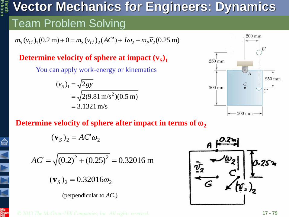
Determine velocity of sphere at impact (vS)1
1 2 2 2( ) (0.2 m) 0 ( ) ( ) (0.25 m)S C S C Pm v m v AC I m v
1
2
( ) 2
2(9.81 m/s )(0.5 m)
3.1321 m/s
Sv gy
You can apply work-energy or kinematics
Determine velocity of sphere after impact in terms of 2
2 2(0.2) (0.25) 0.32016 mAC
2 2( )S AC v
2 2( ) 0.32016S v
(perpendicular to .)AC

© 2013 The McGraw-Hill Companies, Inc. All rights reserved.
Vector Mechanics for Engineers: Dynamics
Ten
thE
ditio
n
Team Problem Solving
17 - 80
Determine mass moment of inertia for panel
1 2 2 2( ) (0.2 m) 0 ( ) ( ) (0.25 m)S C S C Pm v m v AC I m v
Substitute into H equation and solve for 2
2 2 21 1(0.5 m) (8)(0.5) 0.3333 kg m
6 6PI m
1 2 2 2
22 2 2
2
2
( ) (0.2 m) 0 ( ) ( ) (0.25 m)
(2 kg)(3.1321 m/s)(0.2m) (2 kg)(0.32016 )(0.32016 m) 0.3333 (8 kg)(0.25 m)
1.25284 (0.2050 0.3333 0.500)
1.2066 rad/s
S C S C Pm v m v AC I m v

© 2013 The McGraw-Hill Companies, Inc. All rights reserved.
Vector Mechanics for Engineers: Dynamics
Ten
thE
ditio
n
Concept Question
17 - 81
For the previous problem, what would
you do if you wanted to determine how
high up the panel swung after the
impact?
a) Apply linear-momentum to solve for mvG
b) Use work-energy and set Tfinal equal to zero
c) Use sum of forces and sum of moments equations
© 2013 The McGraw-Hill Companies, Inc. All rights reserved.
Vector Mechanics for Engineers: Dynamics
Ten
thE
ditio
n
Concept Question
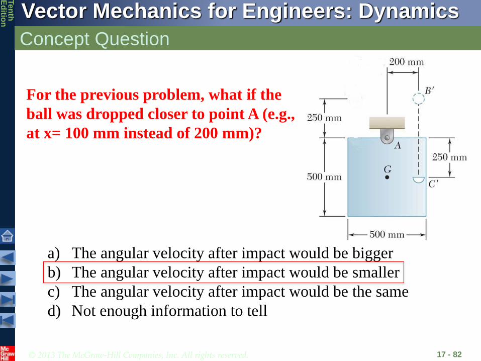
17 - 82
For the previous problem, what if the
ball was dropped closer to point A (e.g.,
at x= 100 mm instead of 200 mm)?
a) The angular velocity after impact would be bigger
b) The angular velocity after impact would be smaller
c) The angular velocity after impact would be the same
d) Not enough information to tell