vendo v-max manual
TRANSCRIPT

Vendo V-Max ManualforCoca-ColaIdentified Equipment
The Vendo Company7209 N. Ingram • Fresno, California 93650 • (559) 439-1770 • fax (559) 439-2083
Vendo P/N 1121848Rev. D
®

TCC-1
PARTS AND SERVICE
MANUAL
P/N: 1121848 REV. D 8/2002

V-MAX COCA-COLA TABLE OF CONTENTS
SAFETY SECTION............................................................................................................... Pages S-1 - S-18 COMMITMENT TO SAFETY ................................................................................................ Page S-2 SAFETY RULES ................................................................................................................... Page S-2 VENDOR INSTALLATION .................................................................................................... Pages S-3 - S-6 ELECTRICAL HAZARDS...................................................................................................... Pages S-7 - S-8
MECHANICAL HAZARDS .................................................................................................... Page S-9 REFRIGERATION HAZARDS .............................................................................................. Page S-10 TEMPERATURE HAZARDS................................................................................................. Page S-10 SUBSTITUTION AND MODIFICATIONS ............................................................................. Pages S-11 - S-12 CONSUMER SAFETY WARNING........................................................................................ Page S-13 GAS ISLAND VENDOR INSTALLATION PROTOCOL........................................................ Page S-14 MOUNTING TO PEDESTAL................................................................................................. Page S-15 PARTS AND SERVICE CENTERS ...................................................................................... Pages S-16 - S-17
GENERAL INFORMATION.................................................................................................. Pages G-1 - G-12 GENERAL INFORMATION................................................................................................... Page G-2
INITIAL SET UP ................................................................................................................... Pages G-3 - G-4 LABEL INSTALLATION ........................................................................................................ Page G-5 ALIGNMENT CHECKS ......................................................................................................... Page G-6 LOADING INSTRUCTIONS.................................................................................................. Page G-7
VEND MECHANISM PARTS DESCRIPTION ...................................................................... Pages G-8 - G-9 VEND CYCLE ....................................................................................................................... Pages G-10 - G-11 9.2 PROGRAMMING SECTION........................................................................................... Pages CP-1 - CP-28
GENERAL ............................................................................................................................. Page CP-2 FOUR-BUTTON PROGRAMMING....................................................................................... Page CP-3 V-MAX CONTROLLER ......................................................................................................... Page CP-4
SET-UP AND CODE DESCRIPTION ................................................................................... Pages CP-5 - CP-23 9.2 WIRING DIAGRAM ........................................................................................................ Pages CP-24 - CP-27
CABINET PARTS SECTION................................................................................................ Pages C-1 - C-18 READING A PARTS LIST..................................................................................................... Page C-2 V-MAX KIT LIST.................................................................................................................... Page C-3 HARDWARE LIST................................................................................................................. Pages C-4 - C-5 INNER DOOR ASSEMBLY................................................................................................... Pages C-6 - C-7 CABINET ASSEMBLY .......................................................................................................... Pages C-8 - C-9 STACK ASSEMBLY.............................................................................................................. Pages C-10 - C-13 REFRIGERATION ASSEMBLY............................................................................................ Pages C-14 - C-15 AIR DAM ASSEMBLY........................................................................................................... Pages C-16 - C-17 V-MAX COCA-COLA PARTS SECTION ............................................................................. Pages CC-1 - CC-10 MAIN DOOR ......................................................................................................................... Pages CC-2 - CC-5 SELECTION PANEL............................................................................................................. Pages CC-6 - CC-7 LOCK ASSEMBLY................................................................................................................ Pages CC-8 - CC-9 MARKETING VENDOR PARTS SECTION ......................................................................... Pages MDC-1 - MDC-14 MAIN DOOR ........................................................................................................................ Pages MDC-2 - MDC-5 SELECTION PANEL............................................................................................................. Pages MDC-6 - MDC-7 LOCK ASSEMBLY................................................................................................................ Pages MDC-8 - MDC-9 INNER DOOR ASSEMBLY................................................................................................... Pages MDC-10 - MDC-11 CABINET ASSEMBLY .......................................................................................................... Pages MDC-12 - MDC-13
TCC-2

V-MAX COCA-COLA TABLE OF CONTENTS MINI V-MAX COCA-COLA PARTS SECTION .................................................................... Page SCC-1 - SCC-10 MAIN DOOR ......................................................................................................................... Pages SCC-2 - SCC-5 SELECTION PANEL............................................................................................................. Pages SCC-6 - SCC-7 LOCK ASSEMBLY................................................................................................................ Pages SCC-8 - SCC-9 V-MAX COCA-COLA ROBO DOOR.................................................................................... Page RDC-1 - RDC-8 ROBO MAIN DOOR.............................................................................................................. Pages RDC-2 - RDC-5 ROBO SELECTION PANEL ................................................................................................. Pages RDC-6 - RDC-7 MAINTENANCE.................................................................................................................... Pages M-1 - M-10 MAINTENANCE.................................................................................................................... Pages M-2 - M-3 REFRIGERATION OPERATION .......................................................................................... Pages M-4 - M-6 REFRIGERATION PARTS DESCRIPTION.......................................................................... Pages M-7 - M-9 TROUBLESHOOTING ......................................................................................................... Pages T-1 - T- 9 VENDO WARRANTY............................................................................................................ Pages T-2 - T-3 PARTS RETURN PROCEDURE.......................................................................................... Page T-4 TROUBLESHOOTING GUIDE ............................................................................................. Pages T-4 - T-8
TCC-3

SAFETY SECTION
3/2002 S-1

A COMMITMENT TO SAFETY
The Vendo Company is committed to safety in every aspect of our product design. Vendo is committed to alerting every user to the possible dangers involved in improper handling or maintenance of our equipment. The servicing of any electrical or mechanical device involves potential hazards, both to those servicing the equipment and to users of the equipment. These hazards can arise because of improper maintenance techniques. The purpose of this manual is to alert everyone servicing Vendo equipment of potentially hazardous areas, and to provide basic safety guidelines for proper maintenance. This manual contains various warnings that should be carefully read to minimize the risk of personal injury to service personnel. This manual also contains service information to insure that proper methods are followed to avoid damaging the vendor or making it unsafe. It is also important to understand these warnings are not exhaustive. Vendo could not possibly know, evaluate, or advise of all of the conceivable ways in which service might be done. Nor can Vendo predict all of the possible hazardous results. The safety precautions outlined in this manual provide the basis for an effective safety program. Use these precautions, along with the service manual, when installing or servicing the vendor. We strongly recommend a similar commitment to safety by every servicing organization. Only properly-trained personnel should have access to the interior of the machine. This will minimize the potential hazards that are inherent in electrical and mechanical devices. Vendo has no control over the machine once it leaves the premises. It is the owner or lessor’s responsibility to maintain the vendor in a safe condition. See Section I of this manual for proper installation procedures and refer to the appropriate service manual for recommended maintenance procedures. If you have any questions, please contact the Technical Services Department of the Vendo office nearest you.
SAFETY RULES • Read the Safety Manual before installation or service. • Test for proper grounding before installing to reduce the risk of electrical shock and
fire. • Turn off power switch or disconnect power cord from wall outlet before servicing or
clearing product jams. The vending mechanism can trap and pinch hands. • Use only fully-trained service technicians for Power- On servicing. • Remove any product prior to moving a vendor. • Use adequate equipment when moving a vendor. • Always wear eye protection, and protect your hands, face, and body when working
near the refrigeration system. • Use only authorized replacement parts. • Be aware of inherent dangers in rocking or tipping a vending machine. • Always turn power off before plugging or unplugging vendor to wall outlet.
3/2002 S-2

SECTION I: VENDOR INSTALLATION
A. Vendors are large, bulky machines of significant size and weight. Improper handling can result in injury. When moving a vendor, carefully plan the route to be taken and the people and equipment required to accomplish the task safely.
B. Remove all tape, shipping sealant, and Styrofoam from the vendor. Loosen any
shipping devices used to secure interior parts during shipping. Remove the wooden shipping base attached to the vendor base by the vendor leveling screws. Make certain the leveling screws are in place and functional.
C. Position the vendor three to four inches (7.6 cm to 10.2 cm) from a well-constructed
wall (of a building or otherwise) on a flat, smooth surface. IMPORTANT: The vendor requires three inches (7.6 cm) of air space from the wall
to ensure proper air circulation to cool the refrigeration unit. D. Adjust the leveling screws to compensate for any irregularities on the floor surface.
Ideally, no adjustment will be necessary and the leveling legs will be flush with the bottom of the vendor. A spirit level is a useful aid to level the vendor. When the vendor is properly leveled the outer door, when opened, will remain stationary. Vendors must be level to ensure proper operation and to maintain stability characteristics. Do not add legs to the vendor.
E. Check the manufacturer’s nameplate on the left or right side of the vendor’s outer
door to verify the main power supply requirements of the vendor. Be sure the main power supply matches the requirements of the vendor. To ensure safe operation, plug the vendor only into a properly grounded outlet.
DO NOT USE EXTENSION CORDS. F. Recommended voltage specs = volts required + amps of circuit. G. Dedicated 15A service required for 1 machine. NOTE: Any power supply variance more than + 10% may cause the vendor to
malfunction. * Power outlets must be properly grounded. * Power outlets must be properly polarized, where applicable. Test the outlets using the following information. (Refer to Figure 1 on Page S-4.)
3/2002 S-3

TYPE 1
TYPE 2
TYPE 3
TYPE 4
TYPE 5
FIGURE 1
EARTH CONTACT SOCKET(GREEN AND YELLOW) 0 VOLTS
OR LIVE (BROWN) 220 VOLTS NEUTRAL (BLUE) 0-5 VOLTS POWER CONTACT SOCKET
OR LIVE (BROWN) 220 VOLTS
POWER CONTACT SOCKETNEUTRAL (BLUE) 0-5 VOLTS
OR LIVE (BROWN) 220 VOLTSNEUTRAL (BLUE) 0-5 VOLTS
POWER CONTACT SOCKET
OR LIVE (BROWN) 220 VOLTS
POWER CONTACT SOCKET NEUTRAL (BLUE) 0-5 VOLTS
POWER CONTACT SOCKETNEUTRAL (BLUE) 0-5 VOLTSOR LIVE (BROWN) 220 VOLTS
EARTH CONTACT (GREEN AND YELLOW) 0 VOLTS
(GREEN AND YELLOW) 0 VOLTS
EARTH CONTACT
STEP 1 STEP 2
STEP 1 STEP 2 STEP 3
STEP 1 STEP 2STEP 3
STEP 3
SMALL SLOT-LINE 1 LIVE CONTACT (BLACK) 110 VOLTS
EARTH CONTACT ROUND SOCKET
EARTH CONTACT SLOT(GREEN AND YELLOW) 0 VOLTS
SLOT LIVE CONTACT
NEUTRAL CONTACT SLOT
(BROWN) 220 VOLTS (BLUE) 0-5 VOLTS
LARGE SLOT-LINE 2NEUTRAL CONTACT (WHITE) 0 - 5 VOLTS
(GREEN) 0 VOLTS
STEP 1
STEP 2 STEP 3
STEP 1STEP 2
STEP 3
OR LIVE (BROWN) 220
POWER CONTACT SOCKET NEUTRAL (BLUE) 0-5 VOLTS
CHECKING FOR PROPER GROUNDING AND POLARIZATION
3/2002 S-4

SECTION I: VENDOR INSTALLATION (CONTINUED) For Type 1 and Type 2 outlets, test for Grounding and Polarization as follows: 1. With a test device (volt meter or test light), connect one probe to the receptacle’s
neutral contact and the other to the live contact. The test device should show a reaction.
2. Connect one probe to the receptacle’s earth contact and the other to the live
contact. The test device should show a reaction. For Type 3 through Type 5 outlets, test for Grounding as follows: 1. With a test device (volt meter or test light), determine which of the receptacle’s
power contacts is the live contact. A. Connect one probe to the receptacle’s earth contact. B. Connect the second probe to the left (or upper) power contact. If a reaction
occurs, this is the live power contact. If a reaction does not occur, move the second probe to the right (or lower) contact. A reaction should occur, indicating that this is the live power contact.
2. Connect one probe to the receptacle’s live power contact (as determined in step 1).
Connect the second probe to the other power contact (neutral). The test device should show a reaction.
IF THE ABOVE CONDITIONS ARE NOT MET FOR THE GIVEN OUTLET TYPE, CONTACT A LICENSED ELECTRICIAN AND HAVE THE NECESSARY CORRECTIONS MADE.
3/2002 S-5

SECTION I: VENDOR INSTALLATION (CONTINUED)
S-6
H. Door Support (Figure 2) The door support is to ensure that the
outer door closes squarely to the cabinet. Raising the door can also ensure proper alignment of the door latch.
FIGURE 2
I. Door Latch Alignment (Figure 3)
DO NOT INSERT OBJECTSINTO LOCK CAVITY.
TO FREE OBJECTS, REMOVELOCK CAP AS SHOWN
12
After any door adjustment, the floating quicker lock assembly should align itself automatically. The latch assembly is adjustable. To adjust, loosen the latch bracket mounting screws, raise or lower the latch assembly into position, then tighten the mounting screws.
SCREWMOUNTING
LATCHBRACKET
FIGURE 3
WARNING: KEEP FINGERS AND OTHER OBJECTS OUT OF LOCK CAVITY
NOTE: Refer to the appropriate parts and service manual for detailed
instructions, operating principles, and recommended maintenance intervals and procedures.
3/2002

SECTION II: ELECTRICAL HAZARDS
GENERAL Vendo vending machines are provided with the appropriate power supply setting for your area. Some models are equipped with step-down transformers, as required. This enables the vending machine to operate on different main voltages. Refer to Section I. E. for information to determine the main power requirements. Refer to the appropriate service manual for details of step-down transformer operations. The power sources just mentioned are standard for both household and commercial lighting and appliances. However, careless or improper handling of electrical circuits can result in injury or death. Anyone installing, repairing, loading, opening, or otherwise servicing a vending machine should be alerted to this point. Apply all of the normal precautions observed in handling electrical circuits, such as: • Refrigeration servicing to be performed by qualified personnel only. • Unplug the vendor or move power switch to off position before servicing or clearing
product jams. • Replace electrical cords if there is any evidence of fraying or other damage. • Keep all protective covers and ground wires in place. • Plug equipment into outlets that are properly grounded and polarized (where
applicable), and protected with fuses or circuit breakers. • All electrical connections must be dry and free of moisture before applying power. A. Grounding Systems Vendo vending machines are provided with the appropriate service cord for the
power supply in your area. The service cord will connect to the matching electrical outlet. Always ensure that the outlet to be used is properly grounded before plugging in the vendor. (See pages S-3 through S-5.)
WARNING: ALWAYS TEST TO VERIFY PROPER GROUNDING PRIOR TO
INSTALLATION TO REDUCE THE RISK OF ELECTRICAL SHOCK AND FIRE
The electrical grounding system also includes the bonding of all metal components within the vendor. This involves a system of bonding wires identified by green or green and yellow marking. The system uses serrated head screws, lock washers, and star washers to ensure the electrical connection between parts. Maintenance of vending equipment may involve disassembly. Include the above items when reassembling, even if the vending machine may appear to function normally without them. Omitting any of these items can compromise a link in the grounding system. See the appropriate service manual or kit instructions for components and assembly instructions.
3/2002 S-7

SECTION II: ELECTRICAL HAZARDS (CONTINUED)
B. Servicing with “Power Off” For maximum safety, unplug the service cord from the wall outlet before opening
the vendor door. This will remove power from the equipment and avoid electrical and mechanical hazards. Service personnel should remain aware of possible hazards from hot components even though electrical power is off. See the appropriate sections of this manual for further information.
C. Servicing with “Power On” Some service situations may require access with the power on. Power on servicing
should be performed only by fully-qualified service technicians. Particular caution is required in servicing assemblies that combine electrical power and mechanical movement. Sudden movement (to escape mechanical action) can result in contact with live circuits and vice versa. It is therefore doubly important to maintain maximum clearances from both moving parts and live circuits when servicing.
WARNING: “POWER-ON” SERVICING SHOULD BE ACCOMPLISHED ONLY BY FULLY-TRAINED PERSONNEL. SUCH SERVICE BY UNQUALIFIED
INDIVIDUALS CAN BE DANGEROUS. Power to lighting and refrigeration system is shut off automatically by the electronic controller when the outer door is opened. Applies to V-Max only. NOTE: For power-on servicing of the vendor’s lighting system, turn lighting power on by
accessing the “LIT” test function of the electronic controller (see programming on inner door). Applies to V-Max only.
For power-on servicing of the vendor’s refrigeration system, turn refrigeration
power on by accessing the “CNPR” test function of the electronic controller (see programming on inner door). Applies to V-Max only.
3/2002 S-8

SECTION III: MECHANICAL HAZARDS
A. Servicing of Moving Parts and Assemblies When servicing assemblies involving moving parts, use extreme caution!! Keep
fingers, hands, loose clothing, hair, tools, or any foreign material clear of entrapment.
As noted before under the electrical hazards section, Power On servicing should
only be performed by qualified personnel. Refer to and heed the warnings noted in the electrical hazards section. These warnings refer to the potential hazards associated with electrical power and moving parts. Always maintain maximum clearances from electrical and moving parts.
Always install protective covers and guards when reassembling equipment.
WARNING: THIS VENDING MACHINE INCLUDES MECHANICAL EQUIPMENT WHICH CAN BE HAZARDOUS IF IMPROPERLY HANDLED OR SERVICED. USE CAUTION AND CONSULT THE VENDO SAFETY MANUAL AND THE VENDO SERVICE MANUAL FOR ADDITIONAL SAFETY INFORMATION.
WARNINGRISK OF ENTRAPMENT RISK OF SHOCK !
WARNINGELECTRICAL !
!
3/2002 S-9

SECTION IV: REFRIGERATION HAZARDS GENERAL Refrigeration systems involve both electrical power and mechanical action. These systems may present any of the potential dangers shown in the sections on electrical and mechanical hazards contained in this manual. See Sections II and III for further information. A. Compressed Refrigerant Refrigeration systems involve the compression and evaporation of gases. The
pressures contained represent a potential hazard if suddenly released in confined areas. Caution is required when performing maintenance tests or repairs. All testing of sealed refrigeration systems must be done by trained personnel who are familiar with the systems and pressures involved.
B. Physical Protection The accidental release of refrigerant gases can result in physical injuries. Always
wear protective glasses and protect your hands, face, and body when working near the refrigeration system.
WARNING: ALWAYS WEAR EYE PROTECTION AND PROTECT YOUR HANDS, FACE, AND BODY WHEN WORKING NEAR THE REFRIGERATION SYSTEM.
SECTION V: TEMPERATURE HAZARDS
GENERAL Maintenance personnel should be alerted to the potential hazards from hot metal surfaces. High temperatures may be present throughout the refrigeration system even though electrical power has been removed.
3/2002 S-10

SECTION VI: SUBSTITUTIONS AND MODIFICATIONS
GENERAL Unauthorized changes or the substitution of unauthorized parts can compromise the equipment designs. This can result in unsafe conditions for either the service personnel or the equipment users. Always refer to the appropriate parts and service manual for replacement parts and maintenance instructions. If questions arise, contact the Technical Services Department of the Vendo office in your area. When servicing the vending machine, always reassemble all components to their original location and position. Maintain the correct routing for tubing, electrical wiring, etc. Replace all clamps, brackets, and guides to their original locations. Replace all tubing, sleeving, insulating material, and protective covers to their original condition.
WARNING: VENDO EQUIPMENT HAS BEEN PROVIDED WITH APPROPRIATE PROTECTIVE DEVICES TO PROTECT AGAINST THE POSSIBILITY OF OVERHEATING AND FIRE AS A RESULT OF EQUIPMENT OR COMPONENT FAILURES. SUBSTITUTION, MODIFICATION, OR BYPASSING OF SUCH PROTECTIVE DEVICES CAN CREATE DANGEROUS CONDITIONS. PROTECTIVE CIRCUITS SHOULD NEVER BE BYPASSED, AND FAILED PROTECTIVE DEVICES MUST BE REPLACED ONLY WITH FACTORY-AUTHORIZED PARTS.
A. Service Cord Replacement Vendo vending machines are furnished with unique power supply cords. If
replacement becomes necessary, consult the appropriate parts and service manual and order the correct replacement cord for the model of vending machine in question. Do not use substitute replacement cords. Only authorized service personnel with appropriate training should replace the vending machine service cord. If a question should arise concerning which service cord to order, contact the Technical Services Department of the Vendo office in your area.
3/2002 S-11

SECTION VI: SUBSTITUTIONS AND MODIFICATIONS (CONTINUED)
WARNING: THIS APPLIANCE MUST BE EARTHED.
IMPORTANT!
The wires in the main leads are colored in accordance with the following code: 110v/120v 220v/240v Green Green and Yellow ............................ Earth White Blue................................................... Neutral Black Brown ............................................... Live
3/2002 S-12

SECTION VII: CONSUMER SAFETY WARNING
WARNING: VENDOR CAN BE OVERTURNED IF SUFFICIENT FORCE IS APPLIED, AND MAY RESULT IN SERIOUS INJURY OR DEATH.
GENERAL There have been incidents, including fatalities, when vending machines have been vandalized by being pulled over in an attempt to obtain free product or money. To warn of the danger involved in tipping, shaking, or rocking the vending machine, a decal has been designed to be affixed to vending machines. (One such decal is supplied with the vending machine.) Vendo will supply sufficient decals to be placed on all machines, on request. If you have any questions, contact the Technical Services Department of the Vendo office in your area.
THE FOLLOWING DECAL SHOULD BE PLACED IN A POSITION ON THE VENDOR CONTROL PANEL AT EYE LEVEL.
Never rock or tilt.Machine can fall overand cause seriousinjury or death.Vending machine willnot dispense freeproduct.
389611A
WARNING
ENGLISH
S-13
SPANISH
AVISO
389611-2A
provee producto gratis.Esta Vendomatica no
graves o matarle.y cauzarle heridasPuede caer sobre ustedesta maquina.Nunca voltie o incline
MISE EN
389611-1A
distribue pas deCette machine ne
des blessures gravesse renverser et causerLe distributeur peutou incliner.Ne jamais secouer
GARDE
ou la morte.
produits gratuitement.
FRENCH
3/2002

GAS ISLAND VENDOR INSTALLATION PROTOCOL
Vendo Gas Island Vending Machines have been evaluated by UL (Underwriters Laboratories Inc.®) for placement at service stations which the NFPA (National Fire Protection Association) considers a hazardous location. These vendors must be correctly installed and inspected per the following protocol before they are put into service.
A. Vendor is to be installed in accordance with the National Electrical Code, NFPA 70, Article 514 - Gasoline Dispensing and Service Stations, NFPA 30A - Automotive and Marine Service Station Code, and the Local Authority Having Jurisdiction.
IMPORTANT - Compliance includes direct wiring of the vendor to the voltage source utilizing proper metal conduit and circuit protection.
B. When installed on support base, the vendor can be installed in an 18-inch high Class I, Group D, Division 2 Hazardous Location. Additionally, the vendor must be installed at least 18 inches from any flammable liquid dispensing device.
Vendor support base is to be attached to vendor as shown by view on page S-15. Vendor should be securely bolted in place using ½-inch nominal diameter hardware as a minimum.
C. IMPORTANT: FOR ANY INSTALLATION REQUIRING LEVELING OF THE VENDOR, IT IS MANDATORY TO OBTAIN APPROVAL OF THE LOCAL AUTHORITY HAVING JURISDICTION. THERE ARE NO EXCEPTIONS. To level more than 1/8 inch, it is suggested to follow these guidelines: 1. Shimming of one or more mounting points should be done with solid steel,
minimum thickness of 1/8 inch. Solid aluminum is acceptable. 2. It is not acceptable to place shims under all (4) mounting points. 3. Shims should be a minimum of 2 ½ inch x 2 ½ inch square or 2 ½ inch diameter. 4. Shim should have a hole, (approximately ½ inch diameter), through the center in
the same manner as the GIV pedestal foot. 5. Shim should be protected against corrosion by painting, plating, etc. 6. IMPORTANT: Hold down bolt should be a solid, continuous bolt.
It is MANDATORY that all installations requiring leveling be approved by the LOCAL AUTHORITY HAVING JURISDICTION.
D. Warning - Power tools with arcing and sparking parts, such as electric drills, should not be used in any hazardous locations during the installation of this vendor.
E. The dispensing area shall be in clear view of the attendant at all times, and placing or allowing any obstacle to come between the dispensing area and the attendant control area shall be prohibited.
F. Upon completion of the installation, the Local Fire Marshall, or Authority Having Jurisdiction, must verify the installation complies with the codes shown in Item A. After authorization, the vendor may be placed into operation.
3/2002 S-14

MOUNTING TO PEDESTAL
LOCK WASHER
HEX BOLT 1/2"-13x1 1/2"
FLAT WASHER
VENDOR
PEDESTAL
FRONT AND REAR COVER
IMPORTANT - INSTALLATION REQUIREMENTS
Electrical equipment, such as vending machines, installed within a 20-ft. radius of a gasoline dispensing unit must meet safety specifications of the National Electrical Code, NFPA 70 - Article 514 - Gasoline Dispensing and Service Stations, NFPA 30A - Automobile and Marine Service Station Code, and the Local Authority Having Jurisdiction. Safety Specifications are: • The vending machine must be UL Listed for installation near gasoline dispensing
equipment. • The vending machine is UL Listed for use in an 18-inch high Class I, Group D,
Division 2 Hazardous Location. • Installation requires ON-SITE approval of Local Fire Marshall, or Authority Having
Jurisdiction. • The vending machine should be securely bolted in place using ½” nominal diameter
hardware as a minimum. Use template provided on pedestal carton for mounting locations. If vendor requires leveling more than 1/8 inch, refer to Page S-14.
• The vending machine must be direct-wired to the voltage source utilizing proper metal conduit and circuit protection.
Note: There are unique safety and approval considerations required for placement of a vendor at the gasoline island which will require a non-standard vending machine. A standard vending machine located at or near the gasoline dispensing area will create unacceptable risks and will not meet safety agency requirements.
3/2002 S-15

PARTS, SALES, & SERVICE CENTERS OF VENDO/SANDEN COMPANY
AREA ADDRESS PHONE NUMBERS United States, Canada
The Vendo Company 7209 N. Ingram Fresno, CA 93650 U.S.A.
Tel: (559) 439-1770 Fax: (559) 439-2083
Japan Sanden International Corporation 31-7 Taito 1-Chome Taito-ku Tokyo 110, Japan
Tel: (81) 3-3835-1321 Fax: (81) 3-3833-7096
Europe, Mid-East, Africa, Mid-Asia
Vendo GMBH Spangerstr. 22, P.O. Box 130940 40599 Dusseldorf Germany
Tel: (49) 211-74-039-0 Fax: (49) 211-7488541
Australia, New Zealand
Sanden International Pty. Ltd. 54 Allingham St., Condell Park N.S.W. 2200 Australia
Tel: 61-2-9791-0999 Fax: 61-2-9791-9029
Singapore, Hong Kong, Indonesia, Philippines, India
Sanden International (Singapore) Pte., Ltd. Sanden House, 25, Ang Mo Kio St. 65 Singapore 569062 The Republic of Singapore
Tel: 65-482-5500 Fax: 65-482-1697
Taiwan Sanden International Taiwan Corp. No, 21-6, Sec 1 Tun Hwa S. Rd., Taipei, Taiwan Taiwan, ROC
Tel: 886-2-570-6106 Fax: 886-2-577-1959
Belgium N.V. Vendo Benelux, S.A. Industrial Research Park N.O.H. 13 Font St. Landry 1120 Brussels Belgium
Tel: 32-2-268-2595 Fax: 32-2-268-2862
England Vendhall, Ltd. Unit 17, The Basingstoke Enterprise Centre Westham Lane, Worting Rd, Basingstoke, Hants RG22, 6NQ Great Britain
Tel: 44-1256-479309 Fax: 44-1256-844469
Italy Vendo Italy S.p.A. Casella Postale 9 1-15033 Casale Monferrato Italy
Tel: 39-142-335111 Fax: 39-142-5623-48
Spain Vendo Iberia, S.A. C/ Sant Ferran No. 92 Poligono Industrial la Almeda, Sector P-1 08940 Cornella, (Barcelona), Spain
Tel: 343-474-1555 Fax: 343-474-1842
3/2002 S-16

PARTS, SALES, & SERVICE CENTERS OF VENDO/SANDEN COMPANY
FOR LATIN AMERICA AREA ADDRESS PHONE NUMBERS
Mexico Vendo de Mexico Camino Real de Toluca No. 154 Col. Bellavista 01140 Mexico D.F. Mexico
Tel: (525) 515-9745 Fax: (525) 277-0111
Central America The Vendo Company 7209 N. Ingram Fresno, CA 93650 U.S.A.
Tel: (559) 439-1770 Fax: (559) 439-2083
Chile Pelp Internacional, S.A. 4560 El Rosal Huechuraba, Santiago, Chile
Tel: (562) 243-9710 Fax: (562) 740-0504
Brazil Cimaq Industria e Comercio de Maq, Ltda. Estrada Uniao e Industria, 9.120 Itaipava 25730-730 Petropolis Rio de Janeiro, Brazil
Tel: (55242) 22-2666Fax: (55242) 22-3244
South America The Vendo Company 7209 N. Ingram Ave. Fresno, CA 93650 U.S.A.
Tel: (559) 439-1770 Fax: (559) 439-2083
3/2002 S-17

NOTES
3/2002 S-18

8/2002 G-1
GENERAL INFORMATION

8/2002 G-2
GENERAL INFORMATION
This manual contains programming, operation, and complete parts and electrical wiring diagrams. The V-MAX controller is a microprocessor which will permit pricing per selection from 0.00 to 99.99. This machine also has space-to-sales programming.
Specifications:
MODEL V-MAX 576 V-MAX 540/720
V-MAX 630/840
V-MAX 512/680
V-MAX 603/800
SELECTIONS 7-8 9-10 9-10 9 or 13 9 or 13 DIMENSIONS (HEIGHT X WIDTH X DEPTH)
CURVED DOOR 72” x 32 ½” x 34 ¾”
72” x 39 ½“ x 35”
79” x 39 ½ “ x 35”
Not Available
Not Available
FLAT DOOR 72” x 32 ½” x 31 ½”
72” x 39 ½” x 32 ½”
79” x 39 ½” x 32 ½”
Not Available
Not Available
MARKETING VENDOR Not Available
Not Available
Not Available
72” x 39 ½” x 34 ¾”
79” x 39 ½” x 34 ¾”
ROBO DOOR Not Available
72” x 39 ½” x 32 ½”
79” x 39 ½” x 32 ½”
Not Available
Not Available
SINGLE COLUMNS 8 10 10 10 10 CAPACITY
PER COLUMN
12 oz. CAN*** 16 oz. GLASS 20 oz. **
72 30 32
72 30 32
84 36 38
51/68 26 30
60/80 32 36
SHIPPING WEIGHT 640 lbs 685 Ibs 750 Ibs 758 lbs 818 lbs OPERATION VOLTAGE 115v 60 Hz. 115v 60 Hz. 115v 60 Hz. 115v 60 Hz. 115v 60 Hz.
AMP. RATING 10 10 10 10 10 REFRIGERATION
VOLTAGE 115v 60 Hz. 115v 60 Hz. 115v 60 Hz. 115v 60 Hz. 115v 60 Hz.
*Dimensions and shipping weight will vary slightly due to manufacturing tolerances, shipping boards and whether or not coinage is installed. ** 20 oz. PET capacity may vary based on the shape and size of the bottle.
***12 oz. Can capacities are listed using a 4-deep set up.
INITIAL SET-UP

8/2002 G-3
A. UNPACKING
Remove all plastic film, cardboard, and tape from the outside of the vendor. Loosen any shipping devices used to secure interior parts during shipment (backspacer, shims, or spacers). To remove shipping boards from base, raise vendor on a well-stabilized lifting device. Remove the leveling bolt which holds the boards in place and remove the boards. Replace bolts to equal heights in the threaded holes. Another method to remove shipping boards is to split the boards apart. Using a pinch bar or a heavy screwdriver and hammer, insert tool into the slots and force the board apart.
B. POSITIONING IMPORTANT: PLACE THE VENDOR IN DESIRED LOCATION AT LEAST THREE TO FOUR INCHES (8 TO 10 CENTIMETERS) AWAY FROM ANY REAR OBSTRUCTION. This is for proper air flow through the refrigeration compartment. The refrigeration system requires front to rear air circulation for proper operation.
C. POWER SUPPLY CONNECTION CAUTION: DO NOT USE AN EXTENSION CORD!
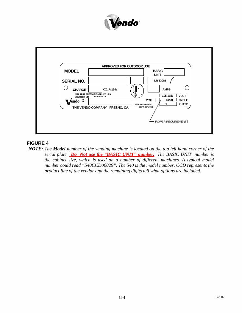
The vendor’s power requirements will vary depending upon the country it was purchased for. To verify the power requirements of the vendor, check the serial plate located on the hinged side of the outer door (see Figure 4 on page G-4). The power requirements are listed on the serial plate. To insure safe operation of the vendor, the vendor’s power supply must be a properly grounded and polarized outlet. Before plugging the vendor into the outlet, test the outlet to confirm it will meet the vendor’s power requirements. If the power supply of the outlet is different from the power requirements of the vendor, a transformer may be necessary. If the power requirements are not properly met, contact a licensed electrician and have the necessary correction made. Should you require additional information, contact the Technical Services Department of the Vendo office in your area.
8/2002 G-4
APPROVED FOR OUTDOOR USE
THE VENDO COMPANY FRESNO, CA.
MIN. TEST PRESSURE APPLIED - PSI
endo
SERIAL NO.
LOW SIDE 140
CHARGE OZ. R-134a
HIGH SIDE 235
MODEL
LR 13085
AMPS
POWER REQUIREMENTS
239L
REFRIGERATEDVENDING MACHINE
R
PHASECYCLEVOLT
150/60
105/115v
UNITBASIC
FIGURE 4 NOTE: The Model number of the vending machine is located on the top left hand corner of the
serial plate. Do Not use the “BASIC UNIT” number. The BASIC UNIT number is the cabinet size, which is used on a number of different machines. A typical model number could read “540CCD00029”. The 540 is the model number, CCD represents the product line of the vendor and the remaining digits tell what options are included.
8/2002 G-5
FIGURE 5 FIGURE 6
COIN INSTRUCTION LABEL
COIN INSERTA
PRICE DISPLAYCOIN INSTRUCTION LABEL
PRICE DISPLAY
STYLE CCOIN INSERTB
STYLE A STYLE B STYLE F
LABEL INSTALLATION
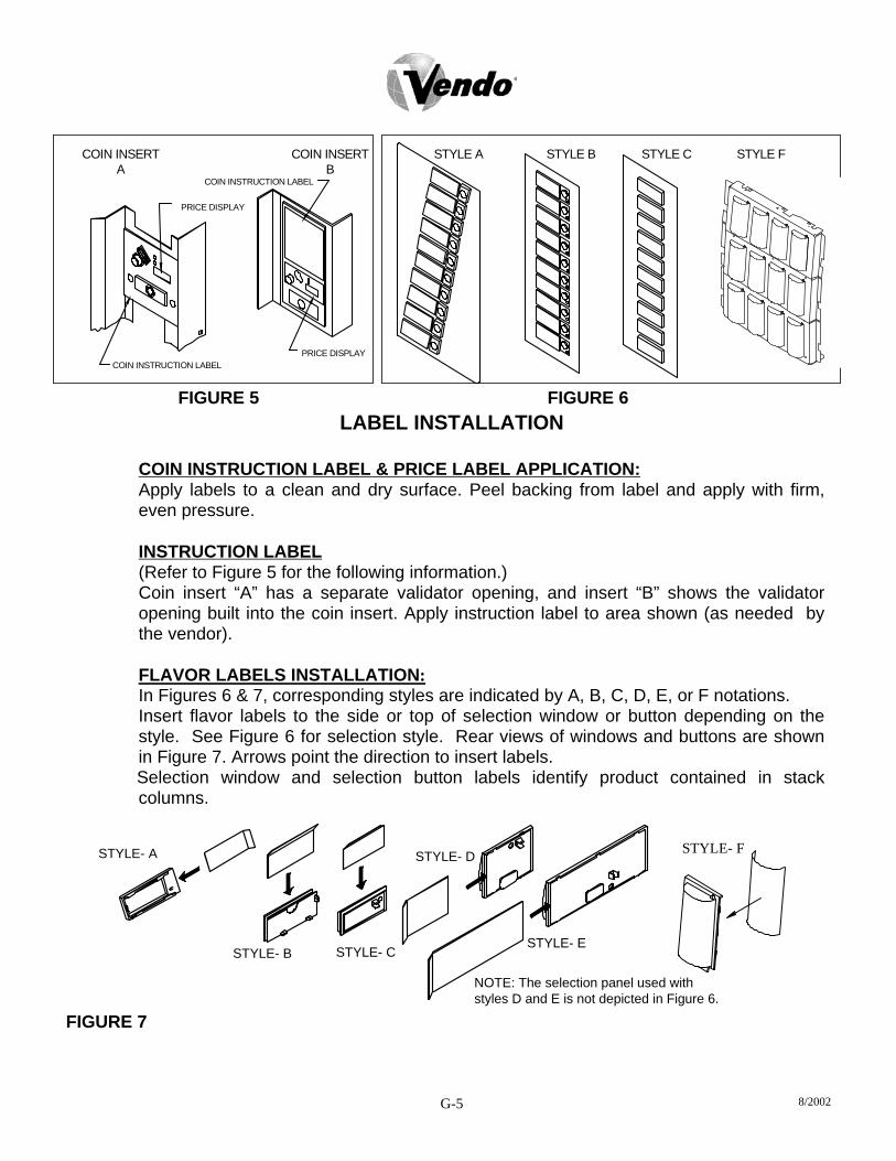
COIN INSTRUCTION LABEL & PRICE LABEL APPLICATION: Apply labels to a clean and dry surface. Peel backing from label and apply with firm, even pressure. INSTRUCTION LABEL (Refer to Figure 5 for the following information.) Coin insert “A” has a separate validator opening, and insert “B” shows the validator opening built into the coin insert. Apply instruction label to area shown (as needed by the vendor). FLAVOR LABELS INSTALLATION: In Figures 6 & 7, corresponding styles are indicated by A, B, C, D, E, or F notations. Insert flavor labels to the side or top of selection window or button depending on the style. See Figure 6 for selection style. Rear views of windows and buttons are shown in Figure 7. Arrows point the direction to insert labels.
Selection window and selection button labels identify product contained in stack columns.
STYLE- DSTYLE- A
STYLE- B STYLE- CSTYLE- E
NOTE: The selection panel used withstyles D and E is not depicted in Figure 6.
FIGURE 7
STYLE- F

8/2002 G-6
DRAIN TUBE
COMPRESSOR
CONDENSER FAN BRACKETCONDENSATION PAN
FIGURE 8 FIGURE 9
ALIGNMENT CHECKS
DOOR RAMP CHECK: The door support is to insure that the outer door closes squarely to the cabinet. Raising the door can also insure proper alignment of the door latch (see Figure 8). REFRIGERATION AREA CHECK: Check the position of the condensation pan (see Figure 9). The correct position of the pan is between the compressor and the condenser fan bracket. Be sure the drain tube is clipped to the pan and is free of kinks. A water trap is installed into the condensation pan and will prevent warm, moist air from reaching the evaporator area.
8/2002 G-7
LOADING INSTRUCTIONS
BASIC LOAD SET-UP: The V-Max machine is capable of vending a variety of products. For specific information, refer to the product set-up label on the machine inner door or contact the Technical Services Department of the Vendo office in your area. Load product evenly. Bottles are loaded with crown end placed toward the back of the column. In initial loading, prime the machine by advancing the product into the buckets. To advance product into buckets, use the vend test function of the electronic controller. When the bucket is loaded, the column is ready to vend.
PRIME ALL COLUMNS DURING INITIAL PRODUCT LOADING

8/2002 G-8
VEND MECHANISM PARTS DESCRIPTION The parts listed below are part of the vend motor mechanism (refer to Figure 10 on page G-9). One mechanism is required per column. The parts are interchangeable. Settings will differ between single, double, triple, and quadruple depth. VEND MOTOR ASSEMBLY: P/N 1115821 The motor is attached to the mech. plate by three screws. TIMING CAM: P/N 1113236, RETAINER: P/N 1113244 The motor cam assembly consists of two parts, the cam and the cam retainer. The cam controls the vend cycle. The cam is attached to the motor by the cam retainer. The retainer rotates left or right, and provides for single, double, triple, or quadruple depth operation. SOLD-OUT SWITCH: P/N 368299 There is one sold-out switch above the vend motor. The sold-out switch is actuated by the sold-out flap when the column is empty. It prevents the motor from running when the columns are empty. STEEL BUCKET: P/N 1120146 The vend bucket holds the product(s) in a “ready to vend” position at the base of each column. MOTOR COUPLING: P/N 1076465 The adapter coupling couples the motor to the bucket. It is located behind the motor, on the motor shaft. ANTI-THEFT CLIP: P/N 389712 The anti-tilt clip prevents product from dropping out of the bucket if the vendor is tilted. The anti-theft clips are located in the bucket.
GATE: P/N 1121282
The gate holds product above the vend bucket.

8/2002 G-9
GATE LINK: P/N 1120140 The rotation of the vend bucket moves the gate link. This opens the gate, allowing one layer of product to drop into the bucket.
GAGE BAR: P/N 1111651 The gage bar holds the product(s) inside the bucket. It also regulates which product is vended first when double, triple or quadruple settings are used (See page G-10 for motor cam settings).
GAGE BAR CLIPS: P/N 1066104(white), 1066112(black), 1066112-1(gray), 1121704(gray), 1122103(black) Gage bar clips are attached to the gage bar to create multiple steps when vending product double, triple, or quadruple depths. (See product set-up label on inner door for details.)
BUCKET
GAGE BAR
GATELINK
SPRING
ANTI-TILT CLIP
SOLD-OUT LEVER
GATE
SWITCH MOUNT
MOTOR CAM GAGE BAR CLIPS
COUPLER
FIGURE 10

8/2002 G-10
VEND CYCLE
Several operations take place during the vend cycle. When a selection is made, the cam and bucket rotate, product is dispensed and the bucket is then reloaded. The sequence of these operations changes slightly when the column’s depth setting is changed. With the single-depth setting, one purchase is made and the bucket is reloaded. The cam sequence occurs one time per bucket revolution. With the double-depth setting, two purchases are made before the bucket is reloaded, and the cam sequence occurs twice per bucket revolution. With triple-depth setting, three purchases are made and the cam sequences three times per bucket revolution. With quadruple-depth setting, four purchases are made and the cam sequences four times per bucket revolution. PURCHASE SEQUENCE: (See Figure 11, quadruple-depth setting pictured) PS 1. Customer inserts money. PS 2. The coinage reports credit to the vending machine electronic controller.
Established credit is displayed on the digital display located near the coin insert slot.
PS 3. Customer presses a selection button. PS 4. The controller receives the signal from the selection switch and (if sufficient credit
exists), energizes the corresponding vend motor. PS 5. The vend motor rotates the bucket and cam. As the cam rotates, the motor position
switch actuator raises to the outer surface of the cam. This closes the switch, which signals the controller to remove credit.
PS 6. Product is immediately dispensed. The motor and cam continue to rotate until the motor position switch actuator drops into the low part of the cam.
PS 7. Motor stops.
FIGURE 11
CAMRETAINER
ITEM 1IN STAND-BY
CAM
POSITION
12
34
2
13
4
2
31
4
IS PS-5 - PS-6ITEM 2
NOTE: The numbers on the cam reflect the number of vends allowed per cycle.
8/2002 G-11
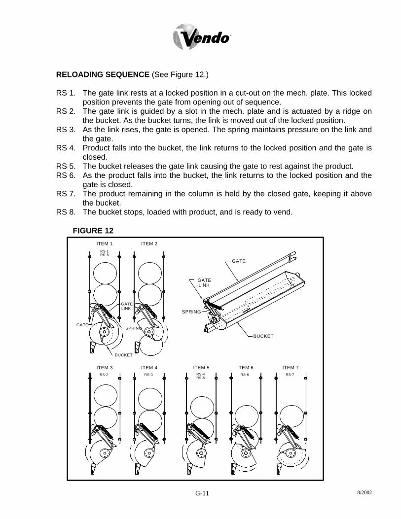
RELOADING SEQUENCE (See Figure 12.)
RS 1. The gate link rests at a locked position in a cut-out on the mech. plate. This locked position prevents the gate from opening out of sequence.
RS 2. The gate link is guided by a slot in the mech. plate and is actuated by a ridge on the bucket. As the bucket turns, the link is moved out of the locked position.
RS 3. As the link rises, the gate is opened. The spring maintains pressure on the link and the gate.
RS 4. Product falls into the bucket, the link returns to the locked position and the gate is closed.
RS 5. The bucket releases the gate link causing the gate to rest against the product. RS 6. As the product falls into the bucket, the link returns to the locked position and the
gate is closed. RS 7. The product remaining in the column is held by the closed gate, keeping it above
the bucket. RS 8. The bucket stops, loaded with product, and is ready to vend.
FIGURE 12
LINK
RS-2 RS-3
ITEM 3
GATE
BUCKET
ITEM 4
SPRING
RS-6RS-4RS-5
ITEM 5
BUCKET
ITEM 6RS-7
ITEM 7
ITEM 2ITEM 1
RS-8RS-1
GATE
LINKGATE
SPRING
GATE

8/2002 G-12
NOTES

9.2 PROGRAMMING SECTION
CP-1 8/2002

All programming of the V-Max is done in the service mode as indicated in the following steps below. The main service modes are indicated in white text and the sub-modes are indicated in black text. Example: Time/Date Setting Mode tIne
Year Setting YeAr
Month Setting Date Setting
nth
dATe Hour Setting Hour Daylight Saving Time
Dst
CP-2 8/2002

FOUR-BUTTON PROGRAMMING
All programming of the V-Max options is done in the service mode. To enter the service mode, open the vendor door and press and release the service mode button, which is located on the control board. (See Figure 1.) The first four selection buttons are used to navigate through the programming as follows:
Button Description Usage Selection Button 1 Abort Escape, Cancel Selection Button 2 Up Increase, Next Selection Button 3 Down Decrease, Previous Selection Button 4 Enter OK, Accept, Save
The control board will automatically return to the open door sales mode if: 1. No information from the selection switches is received within approximately five
minutes. 2. The service mode button is pressed a second time. 3. The (Abort) button is pressed. 4. The “rtn” function is activated. 5. No information from the selection switch is received within 30 seconds while “rtn” is
being displayed. If the door is closed, the control board will exit the service mode and return to the sales mode. When the programming is entered, any established credit is returned to the customer.
CP-3 8/2002

V-MAX CONTROL BOARD
Figure 1
J1J3
J5
J7
J13
J8
J4
J6
J11J10
SERVICE MODEBUTTON
DISPLAY
SWITCHES
CONTROLSRELAY
RESERVED
MOTORS ANDDOOR SWITCH
VEND
INPOWER
AUXVENDO
PORTDEX
MDB PORT
TEMPERATURESENSOR
SELECTION
SERIALNUMBERLOCATEDHERE
9.2
CP-4 8/2002
SET-UP AND CODE DESCRIPTION
Error Display Mode If (Enter) is pressed at the “Eror” prompt, the control board will enter the error display mode. If no errors have occurred, the display will show ”nonE”. If an error has been detected since the last error reset, the display will show the first error summary code that has occurred.
Eror
EXAMPLE: “UEnd” would indicate “COLJ” (a column jam error). If (Enter) is pressed, the control board will display detailed error for the summary code. Pressing (Up and Down) will cycle through any remaining error detail codes. If (Abort) is pressed while displaying any detailed code, the control board will return to the summary code. If (Abort) is pressed while displaying any summary code, the control board will return to the “Eror” prompt. Note: See Figure 2 for Error Code Map. Clearing an Error If (Enter) is pressed and held for two seconds during the display of the detailed error code, that error will be cleared. If other currently accessed detailed errors exist, the next error will now be displayed. If no other errors of this type exist, the next error summary code will now be displayed, or “nonE” if no other errors exist. Coin Pay-out Mode If (Enter) is pressed at the “CPO” prompt, the control board will enter the coin pay-out mode and display the lowest coin value that can be paid out (.5, .10, .25 etc.) The (Up or Down) selection buttons will allow the operator to cycle through the coin tube selections. If (Enter) is pressed, a pay out of the displayed value will be made. Coins will continue to pay out as long as (Enter) is held down. If (Abort) is pressed at any time, the control board will return to the “CPO” prompt.
CPO
EXAMPLE: If (Enter) is pressed while .05 is displayed a nickel will be paid out. Tube Fill Mode If (Enter) is pressed at the “tUFL” prompt, the control board will enter the coin tube fill mode. In this mode, the operator is allowed to deposit any coin into the coin changer’s acceptor when that coin’s tube is not full. The tube inventory level will be displayed after each coin is accepted. If (Abort) is pressed at any time during this operation, the control board will return to the start of the “tUFL” prompt.
tuFL
CP-5 8/2002
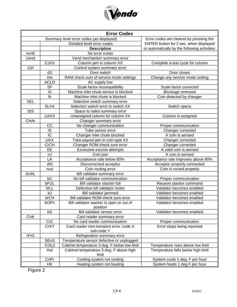
Error Codes
Summary level error codes (as displayed) Error codes are cleared by pressing the Detailed level error codes ENTER button for 2 sec. when displayed Description or automatically by the following activities:
nonE No error exists Uend Vend mechanism summary error
CJXX Column jam in column XX Complete a test cycle for column Ctrl Control system summary error
dS Door switch Door closes rAn RAM check sum of service mode settings Change any service mode setting ACLO AC supply low SF Scale factor incompatibility Scale factor corrected IS Machine inlet chute sensor is blocked Blockage removed Ib Machine inlet chute is blocked Coin detected by changer
SEL Selection switch summary error SLXX Selection switch error in switch XX Switch opens
StS Space to sales summary error UAXX Unassigned column for column XX Column is assigned
CHAr Changer summary error CC No changer communication Proper communication tS Tube sensor error Changer corrected IC Changer inlet chute blocked A coin is sensed tJXX Tube payout jam in coin type XX Changer corrected CrCH Changer ROM check sum error Changer corrected EE Excessive escrow attempts A valid coin is sensed nJ Coin jam A coin is sensed LA Acceptance rate below 80% Acceptance rate improves above 80% dIS Disconnected acceptor Acceptor properly connected rout Coin routing error Coin is routed properly
bUAL Bill validator summary error bC No bill validator communication Proper communication bFUL Bill validator stacker full Receive stacker command bILL Defective bill validator motor Validator becomes enabled bJ Bill validator jammed Validator becomes enabled brCH Bill validator ROM check sum error Validator becomes enabled bOPn Bill validator stacker is open or out of
position Validator becomes enabled
bS Bill validator sensor error Validator becomes enabled Crdr Card reader summary error
CrC No card reader communication Proper communication CrXY Card reader non-transient error: code X
sub-code Y Error stops being reported
rFrG Refrigeration summary error SEnS Temperature sensor defective or unplugged COLd Cabinet temperature 3 deg. F below low limit Temperature rises above low limit Hot Cabinet temperature 3 deg. F above high
limit Temperature falls below high limit
CnPr Cooling system not cooling System cools 1 deg. F per hour Htr Heating system not heating System heats 1 deg F per hour
Figure 2
CP-6 8/2002

SET-UP AND CODE DESCRIPTION (CONTINUED) Test Mode If (Enter) is pressed at the “tESt” prompt, the control board will enter the test mode option. Upon entry into the test mode the display will show the first summary test, “Uend”. Pressing (Up or Down) will cycle through the available tests as listed below. Pressing (Enter) will enter the detailed test mode option. Pressing (Abort) while a summary test prompt is displayed will return the control board to the “tESt” prompt. Pressing (Abort) at the “tESt” prompt has no effect.
tESt
TEST OPTIONS
“Uend” Test vend motor “SL” Test selection switch “SO” Test sold-out switches
“dSP” Check display/LED “rELY” Check compressor, fan, lights and heater relays
Test Vend Motor If (Enter) is pressed at the “tESt” prompt, the “Uend” mode is displayed. If (Enter) is pressed at the “Uend” prompt, the control board will enter the column vend test option. Upon entry into this setting the display will show “CO 1”. This will indicate that a test vend of column 1 may be done. Pressing (Up or Down) will toggle through the available columns. Pressing (Enter) will test vend the displayed column. Pressing (Abort) will return the control board to the “Uend” prompt.
UenD
Selection Switch Test If (Enter) is pressed at the “SL” prompt, the control board will enter the selection switch test option. Upon entry into this setting the display will show “SE 4”. This indicates that the fourth button was pressed last. The last selection switch pressed will remain on the display until the service mode timer expires or the (Abort) button is pressed and held for two seconds. This will return the control board to the “SL” prompt.
SL
Sold-out Switch Test If (Enter) is pressed at the “SO” prompt, the control board will enter the sold-out test option. Upon entry into this setting the display will show “C 10”. This indicates that column 1 is not sold-out. If display shows “C 11” this will indicate that the displayed column is sold-out. Pressing (Up or Down) buttons will toggle through the columns. Pressing (Abort) will return the control board to the “SO” prompt.
SO
EXAMPLE: “0” = Column is not Sold-out.
“1” = Column is Sold-out.
CP-7 8/2002
SET-UP AND CODE DESCRIPTION (CONTINUED)

Check Display/LED If (Enter) is pressed at the “dSP” prompt, the control board will enter the display test option. Upon entry into this setting the display will toggle through all the vertical and horizontal display elements within each digit. The test will continue until the service mode timer expires or the (Abort) button is pressed. This will return the control board to the “dSP” prompt.
dSP
Check Compressor, Light and Heater Relays If (Enter) is pressed at the “rELY” prompt, the control board will enter the relay test option. Upon entry into this setting the display will show the state of the first relay, “CnP0”. This means the relay is not activated and ‘1’ means the relay is activated. Pressing (Enter) will toggle the state of the relay. Pressing (Up or Down) will toggle through the available relays as listed below. Pressing (Abort) will return the control board to the “rELY” prompt. NOTE: All relays will be returned to their initial state, “0”, upon the exit of this test routine.
reLY
EXAMPLE: “0” = Means relay is de-activated. “1” = Means relay is activated.
RELAY LIST
“CnP” Controls the compressor relay “Lit” Controls the sign front light relay “Htr” Controls the heater relay (optional kit)
Note: Pressing (Enter) will return you to “tESt” prompt, pressing (Up) will get you into “PASS”. Password Protection “PASS” will display only if the password has not been entered. The password is entered via the first four selection buttons while the control board is displaying ”PASS”. The password must be entered within 10 seconds in the following order: 4-2-3-1. The display will go blank after the first selection button is pressed. After completing the sequence, press (Enter). If the password is not recognized, the display will remain blank.
PASS
Cash Counter Display Mode If (Enter) is pressed at the “CASH” prompt, the control board will enter the non-resettable cash counter mode by displaying “CASH”. Pressing (Enter) will display cash total over the control board’s life. A decimal will be displayed in the appropriate position. Pressing (Up or Down) will change the display to “CA N”/”XXXX” where “N” is a selection number and the “XXXX” will be replaced with the current re-settable cash amount. Using the (Up or Down) will cycle through the available selections. If (Abort) is pressed at anytime during this operation, the control board will return to the “CASH” prompt.
CASH
SET-UP AND CODE DESCRIPTION (CONTINUED) CP-8 8/2002

Vend Counter Display Mode If (Enter) is pressed at the “SALE” prompt, the control board will enter the non-resettable vend counter display mode by displaying “SALE”. Pressing (Enter) will display the number of all paid vends over the control board’s life. Using (Up or Down) will cycle through each selection as “SL 1”/”0000.” where the “1” indicates the selection and the ‘0’s represent the resettable number of vends for that selection. A decimal will be displayed in the appropriate position. If (Abort) is pressed anytime during this operation, the control board will return to the “SALE” prompt.
SALE
Selection Price Setting Mode PrIC If (Enter) is pressed at the “PrIC” prompt, the control board will enter the selection price setting mode. The display will show “Pr 1” if the machine is in multi-price mode, or “SPrI” if the machine is in single-price mode. In the multi-price mode, individual selection prices can be changed using the (Up or Down) to display “PrXX” where ‘XX’ is the selection number, or choose “ALL” to change the prices for all selection. If (Enter) is pressed, the display will show the current price for the displayed selection. Using (Up or Down) will increase or decrease the price. Holding (Up or Down) for more than five seconds will cause the price to change at 10 times the normal rate. While the desired price is on the display, press (Enter) and the price will be saved. Pressing (Abort) will return to the selection level without saving the new price. Space-to-Sale Programming Mode StS If (Enter) is pressed at the “StS” prompt, the control board will enter the space-to-sales (StS) programming mode by displaying “OPtX” where ‘X’ is the current option selected. Using (Up or Down) will allow the operator to cycle through the available space-to-sales options “Opt1”- “OPt9” and “CSTS”. When one of the options, “OPt1”-“OPt9”, is on the display, pressing (Enter) will select that space-to-sale option and return to the “STS” prompt. If one of the “OPt1”-“OPt9”option is displayed and (Abort) is pressed, the user will return to the “STS” prompt without changing any settings. NOTE: “OPt1”, ”OPt2”, ”OPt8”, “OPt9” are the only configuration settings recommended. Factory setting is “OPt1”. For proper configuration settings refer to the label located on the inner door shear panel. (See figure 3)
CP-9 8/2002

SET-UP AND CODE DESCRIPTION (CONTINUED)
PRE- PROGRAMMED SPACE - TO - SALES
SEL # COLUMNS 1 1,2 1,2 1,2 1,2 1,2,3 1,2,3 1,2 1,2,3 ALL 2 3 1,2 1,2 1,2 1,2,3 1,2,3 3,4 1,2,3 ALL 3 4 3,4 3 1,2 1,2,3 1,2,3 5 4,5 ALL 4 5 5 3 1,2 1,2,3 1,2,3 6 6 ALL 5 6 6 4 3 4 4,5 7 7 ALL 6 7 7 4 4 4 4,5 8 8 ALL 7 8 8 5 5 5 6 9* 9* ALL 8* 9* 9* 6 6 6 6 10* 10* ALL 9* 10* 10* 7 7 7 7 1,2 1,2,3 ALL 10* ~ ~ 8 8 8 8 ~ ~ ~ 11* ~ ~ 9* 9* 9* 9* ~ ~ ~ 12* ~ ~ 10* 10* 10* 10* ~ ~ ~ 13* ~ ~ 1,2 1,2 1,2,3 1,2,3 ~ ~ ~
OPTION 1 2 3 4 5 6 7 8 9 * IF PRESENT Figure 3 Custom Space-to-Sales Mode If (Enter) is pressed at the “CStS” prompt, the control board will enter the custom space-to-sales (CStS) programming mode by displaying “SLXX” where ‘XX’ is the current selection for that certain button, alternating with either “nonE” indicating that no columns are assigned to the displayed selection button or the display will scroll through a sequence of numbers that represents the columns that are currently assigned to the selection button. Using (Up or Down) will cycle through all the available selections and then “SAUE”. Pressing (Abort) will go immediately to the “SAUE” prompt, when pressing the (Abort) button will return the control board to the “CSTS” prompt without changing any settings. Pressing (Enter) while “SAUE” is displayed will save all changes and return the control board to the “STS” prompt.
CStS
Pressing (Enter) while the “SLXX” prompt is displayed will allow columns to be assigned to the current selection. The display will show “Cnn” where “nn” is a column number. Using (Up or Down) will cycle through all the available columns. Pressing (Enter) at any column will enter the edit mode. The display will show “CnnX” where “X” will either be flashing “0”(disabled) or “1”(enabled) to assign the columns (“nn”) to the current selection. Using (Up or Down) will change the assignment status of the columns. Pressing (Abort) will return the control board to the “Cnn” prompt without changing the status of the column, while pressing (Enter) saves the displayed status of the column before returning to the “Cnn” prompt. Pressing (Abort) at the “CnnX” prompt returns the control board to the “SLXX” prompt. EXAMPLE: “Cnn0” = The selection is disabled. “Cnn1” = The selection is enabled.
CP-10 8/2002

SET-UP AND CODE DESCRIPTION (CONTINUED) Machine Configuration Mode Con If (Enter) is pressed at the “Con” prompt, the control board will enter the machine configuration mode by displaying “C1 X” which indicates configuration options number 1 and the “X” is the current status of that setting. If “X” is 1 then status is active, if “X” is “0” then the status is not active. If (Abort) is pressed while at the “C1 X” prompt the control board will return to the “Con” prompt. Pressing (Up or Down) will toggle through the available configuration options. Pressing (Enter) saves the status of the current option and returns the user to the “Con” prompt. Pressing (Abort) returns the control board to the “Con” prompt without saving. (See Figure 4.) EXAMPLE: “0” = The Con is disabled.
“1” = The Con is enabled.
CONFIGURATION SETTINGS
C1
C2
C3
C4
C5
C6
C7
C8
C9
C10
CON#
PRICE SETTING
OPTIONAL FEATURES
POS MESSAGE
DOOR OPEN MIS
MIS RESET
RESERVED
SAVE CREDIT
FORCE VEND
MULTI VEND
BILL ESCROW
DESCRIPTION0=SINGLE PRICE
0=DISABLE OPTIONAL PROGRAM
0=DISPLAY POS MESSAGE
0=DISPLAY SUMMARY ERROR CODES
0=RESET MIS VIA DEX COMMAND ONLY1=RESET MIS WHEN DOOR IS CLOSED
0=SAVE CREDIT FOR 5 MINUTES1=SAVE CREDIT INDEFINITELY0=NORMAL VEND1=FORCE VEND0=SINGLE VEND1=MULTI VEND
1=DISABLE BILL ESCROW0=ENABLE BILL ESCROW
1=MULTI PRICE
1=ENABLE OPTIONAL PROGRAM
1=TURN OFF POS MESSAGE
1=DISPLAY SUMMARY SALES DATA
SETTINGS
Figure 4
CP-11 8/2002

SET-UP AND CODE DESCRIPTION (CONTINUED) Single/Multi-Price Mode Toggles between the single-price and multi-price modes. In the single-price mode, the price of selection 1 will be used for all selections. In the multi-price mode, each selection can be set to a different price.
C1
“0” = Single pricing is used. “1” = Multi-pricing is used. Optional Feature Enable This selection will allow optional features to be enabled and displayed in the current service mode menu. If any of the optional features described in this document are implemented, they must be able to be hidden by this selection. These features currently include “bLC1”, “bLC2”, “dISC” and “OUEr”.
C2
“0” = Option is Off. “1” = Option is On. LED Display Message Mode Toggles between the LED display modes. In the display/LED mode, the current price will be displayed if in the single price mode. Note: ICE COLD COCA COLA will scroll when the option is set at “0”.
C3
“0” = Display message is On. “1” = Display message is Off. Door Open MIS Mode This option changes the Open-Door Mode Display. If enabled, the total machine sales and total machine cash values are displayed before the error codes. These values represent the number of all paid vends and the cash amount of all paid vends, respectively. The sales and cash values are displayed the same as in the “SALE” and “CASH” service mode functions. The display shows “SALE”/”0000”/”0000” for two seconds on the display/LED, then “CASH”/”0000”/”00.00”, then “Eror” or “nonE”. If this option is disabled, existing errors are displayed, or “nonE” for no detected errors.
C4
“0” = Existing errors or “nonE” is displayed. “1” = “SALE”/”0000”/”0000” “CASH”/”0000”/”00.00” and “Eror” or “nonE”.
CP-12 8/2002

SET-UP AND CODE DESCRIPTION (CONTINUED)
MIS Reset Mode This option is used to allow the door switch to reset all re-settable MIS. It will be reset only if the “CASH” and “SALE” mode were entered.
C5
“0” = All re-settable MIS registers will be reset only when the “CF” command is received
from the HHC. “1” = All re-settable MIS registers are reset when the door switch is activated if any of the
re-settable MIS registers are read.
RESERVED FOR FUTURE PROGRAMMING.
C6 Save Credit Mode This option is used to determine how long credit should be maintained on the display and available to the customer. If “Save Credit” is enabled it will register the credit for no more than five minutes, after the vend is aborted and returns to standby.
C7
“0” = Clears credit in five minutes. “1” = Credit remains. Force Vend Prevents the machine from making change without a selection being attempted. When this mode is enabled, escrow of coins is allowed until any of the following:
C8
A. Any bill is inserted into the bill acceptor; B. Any “cash box” coin (a coin that is not assigned to a tube) is inserted, or; C. The maximum vend price is reached. Once any of these conditions are met, an
escrow request is ignored and a vend must be made. If a selection is made that is sold-out or locked out, this option will be overridden and an escrow request will be honored. NOTE: Force vend has no effect on the card reader. Once a card is inserted, it can always be returned to the customer via an escrow or the return switch on the card reader. “0” = Force-vend is disabled. “1” = Force-vend is enabled.
CP-13 8/2002

SET-UP AND CODE DESCRIPTION (CONTINUED)
Multi-Vend Allows multiple purchases without re-entering coins. If enabled, instead of returning the change after a vend, the credit will remain on the display to be used for another selection. An escrow will be honored at any time. This option will take precedence over the force-vend option after the first vend has been completed.
C9
“0” = Multi-vend is disabled. “1” = Multi-vend is enabled. Bill Escrow Mode Allows the escrow of bills. If enabled and the bill value inserted takes the accumulated credit over the maximum price, the bill will be held in the escrow position. If the rule is disabled, bills will always go to the stacker.
C 10
“0” = Bill escrow is disabled. “1” = Bill escrow is enabled. Correct Change Only Control Allows the customer to disable or enable the overpay routine. CCOC
If “Con0”, Consumer overpay routine disabled for USA. If “Con1”, Can be enabled for International use. If “CCU”, “Correct Change Value” is the value that the control board has the ability to
control the “Use Correct Change Only” option. If “ACC”, “Unconditional Acceptance Value” is the largest value of any single form of
currency that can be accepted without knowledge that the equivalent value of coins can be returned. This option applies to coins or bills.
Preview Vend Password Setting Mode If (Enter) is pressed at the “PrEU” prompt, the control board will display the current password for the preview vend mode. The first digit of the number will be flashing. Pressing (Up or Down) will adjust the currently flashing digit up or down. Pressing (Enter) will save the currently flashing digit and the next digit of the password will begin flashing. All digits may be modified in this manner. Pressing (Enter) while the last digit is flashing saves the currently displayed password and return to the “PrEU” prompt. Pressing (Abort) at any time in the procedure returns to the “PrEU” prompt without saving.
PrEU
CP-14 8/2002

SET-UP AND CODE DESCRIPTION (CONTINUED) Change Language If (Enter) is pressed at the “LAnG” prompt, the control board will display the current language for the preview mode. Pressing (Up or Down) will toggle through the available languages listed below. Pressing (Enter) will activate the displayed language and return to the ”LAnG” prompt. Pressing (Abort) at any time in the procedure returns to the control board to the “LAnG” prompt without changing the active language.
LAnG
LANGUAGE LIST “EnG” English - mandatory if supported “Frn” French - mandatory if supported “Ger” German - mandatory if supported “ItA” Italian - mandatory if supported
“Port” Portuguese - mandatory if supported “ESP” Spanish - mandatory if supported “SLO” Slovene - mandatory if supported
Time/Date Setting Mode If (Enter) is pressed at the “tinE” (time) prompt, the control board will enter the time/date setting mode and display “Enb0” (disable) or “Enb1” (enable). Using (Up or Down) will allow the control board to cycle through all available time selection options. If (Abort) is pressed anytime during this operation, the control board will return to the “tInE” prompt.
tIne
TIME SELECTION OPTIONS “Enb1” Enable/Disable time (Edit mode 0/1) “YEAr” Current Year (Example ’02) “dAtE” Current Date (month, day) “nth” Current Month
“hour” Current Time (hours, minutes) “dSt” Daylight Saving Time
Year Setting Option If (Enter) is pressed at the “YEAr” prompt, the last two digits of the year are displayed and will be flashing. Pressing (Up or Down) will increase or decrease the year setting. Pressing (Enter) will save the displayed year setting and return the user to “YEAr”. Pressing (Abort) will return to “YEAr” without saving.
YeAr
Month Setting Option If (Enter) is pressed at the “nth” prompt, the control board will enter the month setting option. Upon entry into this option the display will show the current two-digit month setting, indicating the month of the year (example: 01-12). Pressing (Up or Down) will increase or decrease the month setting. Pressing (Enter) will save the displayed month setting and return the Control board to the “nth” prompt. Pressing (Abort) while the month digits are flashing returns to the “nth” prompt without saving the month.
nth
CP-15 8/2002

SET-UP AND CODE DESCRIPTION (CONTINUED)
Date Setting Option If (Enter) is pressed at the “dATE” prompt, the current two-digit date (days of the month) is displayed. Pressing (Up or Down) will increase or decrease the date setting. Pressing (Enter) will save the displayed date and return to the “datE” prompt. Pressing (Abort) while the date digits are flashing returns to the “datE” prompt without saving the new date.
dATE
Hour Setting Option If (Enter) is pressed at the “Hour” prompt, the current time is displayed in a 24-hour format. The left two digits of the display show the hour and the right two digits show the current minutes. While the hour digits are flashing, pressing (Up or Down) will increase/decrease the hour. Pressing (Enter) at this point will save the displayed hours and the minute digits will start to flash. While the minute digits are flashing, pressing (Up or Down) will increase/decrease the minutes. Pressing (Enter) at the point will save the displayed hours and minutes and return to the “Hour” prompt. Pressing (Abort) while the hour or minute digits are flashing returns to “Hour” without saving the hour or minutes.
Hour
Daylight Saving Time If (Enter) is pressed at the “Dst” prompt, the current daylight saving time option will be displayed. Using (Up or Down) will toggle the different countries: AUS (Australian rules), EU (European rules), OFF (No daylight savings) and NA (North American rules). If (Enter) is pressed at this point, the current display option will be saved and the user will be returned to the “DSt” prompt. Pressing (Abort) returns to the “DSt” prompt without saving.
Dst
Light Control If (Enter) is pressed at the “Lit” prompt the control board will enter the light control programming mode by displaying “Enb0”(disable) or “Enb1” (enable). Using (Up or Down) will allow the operator to cycle through all available time selection options. If (Abort) is pressed anytime during this operation, the control board will return to the code level.
LIt
LIGHT CONTROL OPTIONS “Enb1” Enable/Disable light timer (Edit mode 0/1) “Strt” Set start time “dAY” Set days to time “Hour” Set time to start (24 hours) “StoP” Set stop time
CP-16 8/2002

SET-UP AND CODE DESCRIPTION (CONTINUED)
Set Enable/Disable If (Enter) is pressed at the “Enbx” prompt, the last digit of the prompt will start flashing. Pressing (Up or Down) will toggle from “1” (Enable) to “0” (Disable). Pressing (Enter) will save the displayed setting and return the user to “EnbX”. Pressing (Abort) will return to “EnbX” without saving.
EnbX
“0” = Setting is disabled. “1” = Setting is enabled. Start Time Setting If (Enter) is pressed at the “Strt” prompt, the control board will enter the start time setting option. Upon entry into this option the display will show “dAY”. Pressing (Up or Down) will cycle through the available summary level codes. Pressing (Enter) will enter the detail level option. Pressing (Abort) while a summary level prompt is displayed will return the control board to the “Strt” prompt. Pressing (Abort) at the “Strt” prompt will return the control board to the “Lit” prompt.
Strt
Day Setting Option If (Enter) is pressed at the “dAY” prompt, the current day of the week is displayed. The days are displayed as follows:
dAY
“nonX” Monday “tuEX” Tuesday “WEdX” Wednesday “thuX” Thursday “FriX” Friday “SAtX” Saturday “SunX” Sunday “ALL” All Days “0” = Setting is disabled. “1” = Setting is enabled. Pressing (Up or Down) at this point will rotate through the days of the week. Pressing (Enter) when a day (e.g. nonX) is displayed will cause the “X” to flash. Pressing (Up or Down) will toggle from “0” (disable) to “1” (enable). If (Enter) is pressed, the displayed day is saved and the user is returned to the “dAY” prompt. Pressing (Abort) returns the control board to the “dAY” prompt without saving.
CP-17 8/2002
SET-UP AND CODE DESCRIPTION (CONTINUED) Start Hour Setting If (Enter) is pressed at the “Hour” prompt, the current time is displayed in a 24-hour format. The left two digits of the display will show the hour and the right two digits show the current minutes. While the hour digits are flashing, pressing (Up or Down) will increase/decrease the hour. Pressing (Enter) at this point will save the displayed hours and the minute digits will start to flash. While the minute digits are flashing, press (Up or Down) to increase/decrease the minutes. Pressing (Enter) at this point will save the displayed hours and minutes and return to the “Hour” Prompt. Pressing (Abort) while the hour or minutes digits are flashing returns to “Hour” without saving.
Hour
Set Stop Time If (Enter) is pressed at the “StoP” prompt, the control board will enter the stop time setting option. Upon entry into this option the display will show “dAtE”. Pressing (Up or Down) will cycle through the available summary level codes. Pressing (Enter) will enter the detail level option. Pressing (Abort) while a summary level prompt is displayed will return the control board to the “StoP” prompt. Pressing (Abort) at the “StoP” prompt will return the control board to the “Lit” prompt. Note: To program days and hours refer to page CP-15.
StoP
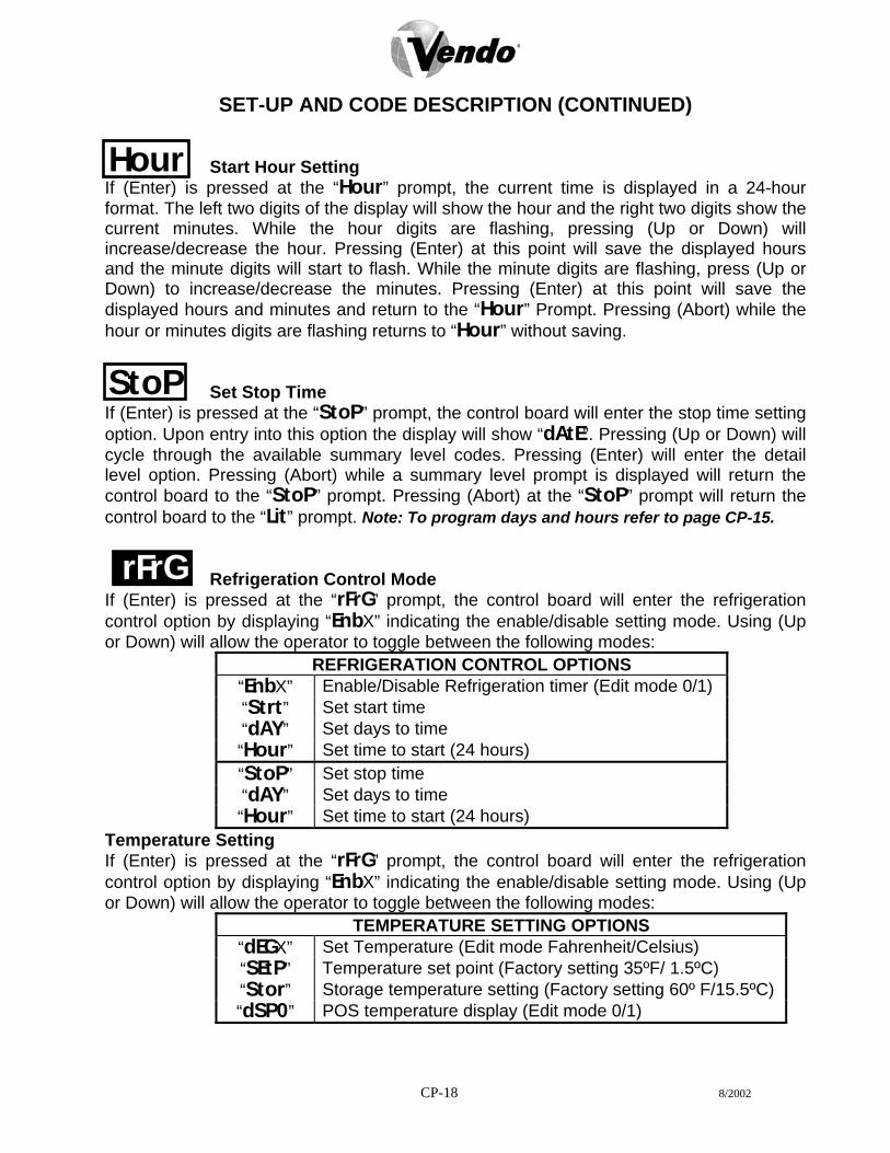
Refrigeration Control Mode rFrG
If (Enter) is pressed at the “rFrG” prompt, the control board will enter the refrigeration control option by displaying “EnbX” indicating the enable/disable setting mode. Using (Up or Down) will allow the operator to toggle between the following modes:
REFRIGERATION CONTROL OPTIONS “EnbX” Enable/Disable Refrigeration timer (Edit mode 0/1) “Strt” Set start time “dAY” Set days to time “Hour” Set time to start (24 hours) “StoP” Set stop time “dAY” Set days to time “Hour” Set time to start (24 hours)
Temperature Setting If (Enter) is pressed at the “rFrG” prompt, the control board will enter the refrigeration control option by displaying “EnbX” indicating the enable/disable setting mode. Using (Up or Down) will allow the operator to toggle between the following modes:
TEMPERATURE SETTING OPTIONS “dEGX” Set Temperature (Edit mode Fahrenheit/Celsius) “SEtP” Temperature set point (Factory setting 35ºF/ 1.5ºC) “Stor” Storage temperature setting (Factory setting 60º F/15.5ºC) “dSP0” POS temperature display (Edit mode 0/1)
CP-18 8/2002

SET-UP AND CODE DESCRIPTION (CONTINUED) Degree Setting If (Enter) is pressed at the “dEGX” prompt, the control board will display “dEGX” where ‘X’ will be ‘F’ if the control board is currently in ºF (Fahrenheit) mode or ‘C’ if the control board is currently in ºC (Celsius) mode. Pressing (Up or Down) while the “X” digit is flashing will toggle the ‘X’ digit between ‘F’ and ‘C’. Pressing (Enter) will save the displayed temperature mode and return to the “dEGX” prompt. Pressing (Abort) will return to the “dEGX” prompt without saving.
dEGX
Set Point Setting (35ºF) If (Enter) is pressed at the “SEtP” prompt, the control board will display “XX.XX” where ‘X’ will be the current set point temperature. Pressing (Up or Down) will increase/decrease by one degree increments. Pressing (Enter) will save the displayed temperature setting and return the user to the “SEtP” prompt. Pressing (Abort) will return to the “SEtP” prompt without saving.
SEtP
Storage Temperature Setting (60ºF) If (Enter) is pressed at the “Stor” prompt, the control board will display “XX.XX” where ‘X’ will be the current storage temperature. Pressing (Up or Down) will increase/decrease by one degree increments. Pressing (Enter) will save the displayed storage temperature setting and return the user to the “Stor” prompt. Pressing (Abort) will return to the “Stor” prompt without saving.
Stor
Display Temperature If (Enter) is pressed at the “dSP0” prompt, the control board will enter into the LED temperature display enable option. Upon entry into this option the display will show the current setting “dSP0” where the “0” is flashing will disable the temperature from being shown in the LED or if “1” is flashing the temperature will be displayed in the LED following “ICE COLD COCA COLA”. Pressing (Up or Down) will toggle the digit between ‘0’ and ‘1’. Pressing (Enter) will save the currently displayed setting and return to the “dSP0” prompt. Pressing (Abort) will return to the “dSP0” prompt without saving.
dSP0
CP-19 8/2002

SET-UP AND CODE DESCRIPTION (CONTINUED) Block Selection Setting If (Enter) is pressed at the “bLC1” or “bLC2” prompt, the control board will enter the second bank of selection blocking control option. Upon entry into this routine the display will show the first summary level code “Enb0”. Pressing (Enter) will save the currently displayed setting and return the user to the “bLC1” prompt. Pressing (Abort) will return to the “bLC1” prompt without saving. Using (Up or Down) will let the operator toggle between the following modes: Note: “BLC1” will not be accessible when “C2” is set at “0”. “0” = Block option is disabled. “1” = Block option is enabled.
BLOCK SELECTION OPTIONS “EnbX” Enable/Disable selection blocking (Edit mode 0/1) “Strt” Set start time “dAY” Set days to time “Hour” Set time to start (24 hours) “StoP” Set stop time “dAY” Set days to time “Hour” Set time to start (24 hours) “SEL” Set selection time
Discount Setting Mode If (Enter) is pressed at the “dISC” prompt, the control board will enter the discount control setting blocking control routine. Upon entry into this setting the display will show the first summary level code “Enb0”. If (Up or Down) is pressed it will cycle through the available summary level codes as listed below. Pressing (Enter) will save the currently displayed setting and return the user to the “dISC” prompt. Pressing (Abort) will return to the “dISC” prompt without saving. Using (Up or Down) will let the operator toggle between the following modes: Note: “dISC” will not be accessible when “C2” is set at “0”. “0” = Disabled discount setting. “1” = Enabled discount setting.
DISCOUNT SETTING OPTIONS “EnbX” Enable/Disable discount setting (Edit mode 0/1) “Strt” Set start time “dAY” Set days to time “Hour” Set time to start (24 hours) “StoP” Set stop time “dAY” Set days to time “Hour” Set time to start (24 hours) “SEL” Set selection time
“LESS” Set Discount amount
dISC
BLC 1
CP-20 8/2002

SET-UP AND CODE DESCRIPTION (CONTINUED)
Selection Setting If (Enter) is pressed at the “SEL” prompt, the control board will enter the selection setting option. Upon entry into this setting the display will show the current setting for selection as “01 1”, where “1” shows it is enabled or “0” if the option is disabled. If (Up or Down) is pressed it will cycle through the valid selections or “ALL”. Pressing (Enter) will save the currently displayed setting and return the control board to the “SEL” prompt. Pressing (Abort) will return the control board to the “SEL” prompt without saving.
SEL
“0” = Selection setting is disabled. “1” = Selection setting is enabled. Selection Setting If (Enter) is pressed at the “LESS” prompt, the control board will enter the discount amount option. Upon entry into this setting the display will show the current four digit discount amount. If (Up or Down) is pressed it will increase or decrease the lowest discount amount. Pressing (Enter) will save the currently displayed setting and return the user to the “LESS” prompt. Pressing (Abort) will return to the “LESS” prompt without saving.
LESS
Over-Ride Option Mode (Units equipped with optional key switch) If (Enter) is pressed at the “OUEr” prompt, the control board will enter the over-ride option. Upon entry into this setting the display will show the first summary level code “FrEX”. If (Up or Down) is pressed it will cycle through the available summary level codes as listed below. Pressing (Enter) will save the currently displayed setting and return the user to the “OUEr” prompt. Pressing (Abort) will return to the “OUEr” prompt without saving. Using (Up or Down) will let the operator toggle between the following modes:
OUEr
“0” = Disabled over-ride option. “1” = Enabled over-ride option. Note: “OUEr” will not be accessible when “C2” is set at “0”.
OVERRIDE SETTING OPTIONS “FrE0” Enable/Disable free vend (Edit mode 0/1) “bLC0” Selection blocking over-ride “dSC0” Discounting over-ride “Lit0” Lighting control over-ride “FrG0” Refrigeration control over-ride
CP-21

SET-UP AND CODE DESCRIPTION (CONTINUED) Over-Ride Free Vend If (Enter) is pressed at the “FrE0” prompt, the control board will enter the free vend enable option. Upon entry into this setting the display will show the current setting “FrE0”. Pressing (Up or Down) will toggle between ‘0’(disable) or ‘1’(enable). Pressing (Enter) will save the currently displayed setting and return to the “FrE0” prompt. Pressing (Abort) will return to the “FrE0” prompt without saving.
FrE0
“0” = Disabled free vend. “1” = Enabled free vend. Over-Ride Selection Blocking If (Enter) is pressed at the “bLC0” prompt, the control board will enter the selection blocking over-ride enable option. Upon entry into this setting the display will show the current setting “bLC0”. Pressing (Up or Down) will toggle between ‘0’ (disable) or ‘1’ (enable). Pressing (Enter) will save the currently displayed setting and return the user to the “bLC0” prompt. Pressing (Abort) will return to the “bLC0” prompt without saving.
Blc0
“0” = Disabled selection blocking. “1” = Enabled selection blocking. Over-Ride Discount If (Enter) is pressed at the “dSC0” prompt, the control board will enter the discounting over-ride enable option. Upon entry into this setting the display will show the current setting “dSC0”. Pressing (Up or Down) will toggle between ‘0’ (disable) or ‘1’ (enable). Pressing (Enter) will save the currently displayed setting and return to the “dSC0” prompt. Pressing (Abort) will return to the “dSC0” prompt without saving.
dSC0
“0” = Disabled discount over-ride. “1” = Enabled discount over-ride. Over-Ride Lighting Control If (Enter) is pressed at the “Lit0” prompt, the control board will enter the lighting control over-ride enable option. Upon entry into this setting the display will show the current setting “Lit0”. Pressing (Up or Down) will toggle between ‘0’ (disable) or ‘1’ (enable). Pressing (Enter) will save the currently displayed setting and return to the “Lit0” prompt. Pressing (Abort) will return to the “Lit0” prompt without saving.
LIt0
“0” = Disabled lighting control. “1” = Enabled lighting control.
CP-22

SET-UP AND CODE DESCRIPTION (CONTINUED) Over-Ride Refrigeration Control If (Enter) is pressed at the “FrG0” prompt, the control board will enter the refrigeration control over-ride enable option. Upon entry into this setting the display will show the current setting “FrG0”. Pressing (Up or Down) will toggle between ‘0’ (disable) or ‘1’ (enable). Pressing (Enter) will save the currently displayed setting and return to the “FrG0” prompt. Pressing (Abort) will return to the “FrG0” prompt without saving.
FrG0
“0” = Disabled refrigeration control over-ride. “1” = Enabled refrigeration control over-ride.
CP-23

CP-24
9.2 WIRING DIAGRAM (COCA-COLA)
PHILLIPS ELECTRONIC
LAMP
LAMP
LAMP
LAMP
SLIM LINESEL. # 13
VIO
WHT(WHEN USED)
BLU PNKWHT
20 1191817
987
GRYVIOYEL
16151413
ORNBRN
6543
1112 2
1J6
ORN
RED
BLK8 47 3
VIO15
6 2
J4
BRN
WHT
SEL. # 12
BRN
WHT
YEL
SEL. # 10
SEL. # 11
GRY
BLU
SEL. # 9
ORN
BLU
VIO
SELECTION SWITCHES
SEL. # 8
SEL. # 7
BLU
BRN
BLU
SEL. # 6
YEL
BLU
GRY
SEL. # 5
SEL. # 4
PNK
ORN
PNK
SEL. # 3PNK
VIO
ORN
SEL. # 1
SEL. # 2
COM
PNK
YEL
NO PNK
4BLKRED
DISPLAY1
VIO
(WHEN USED)
(WHEN USED)
(WHEN USED)
(WHEN USED)
(WHEN USED)
BALLAST
HIGH OUTPUT
2
1
2
1
OSRAM ELECTRONIC
BALLAST
LAMP
DOOR
2
1
BALLAST
LAMP
BALLAST
1
2
LAMP
LAMP
GRN
GRNWHT3
412
BLK
J13
GRYVIOYEL
10 5
89
7ORN
432
J11
6BRN 1
J8SOCKETMDB
YEL9
J10
1
PNKGRYVIO10
111213
2345
REDWHT
141516
678BLK
BLU
BRNORN
WHT
J7
987
432
10 5
16
MODESWITCH
15234
678
SOCKETDEX
J3
J5
12
J13 BLK
WHTRED
VEC 9.2CONTROL BOARD
BRNORNGRY
WHTBLK
8
VIO
ORN
BLUBLKWHT12
1 YEL
GRY
REDWHTBRN
PNK
1
VIOYEL
REDWHT
SHLD
BLK4
1
GRN
DOOR
VOLTAGE READINGS J1 - Temp Sensor 5 Volts DC Pins 1 and at 2 J8 - MDB Port 34 Volts DC Pin 1 5 Volts at Pin 6 J3 - DEX Port only 0 Volts DC J10 - Vend Motor Port 15 Volts DC Pins 1 and 12, 24 Volts
at Pins 8 and 16, and 13 Volts at Pin 3, 4 and 10 J4 - Display Port 5 Volts DC at Pins 6 and at 3 J11 - Environmental Control Port 24 Volts DC Pins 1,2 and
3 J5 - Option Port 5 Volts DC Pin 1, 2, 3, 4, 7 J13 - Main Power Input 24 Volts AC Pin 3 J6 - Selection Port 5 Volts DC Pins 3, 4, 5, 13, 14 All Power readings were off the J13 Pin 2 ground

CP-25
9.2 WIRING DIAGRAM (CONTINUED)
WHT
WHT
2
BLK1
OR
110 VOLT AUXILIARY PLUG
110VAC
WHT32
BLK1
110VAC
WHT
BLK
220VAC
WHTSNA
BLK
GRN
RT
WHT
23
BLK1
(110 VOLTCAPACITOR
COMPRESSOR
VIO
GRN
DOOR
CABINET
8
WHTBLK
GRN
YELVIO
ORNGRY
121
WHTBLKBLU
ORNBRNWHTREDPNKGRY
4
REDWHTBLKSHLD
YEL 1
1
DOOR
CABINET
SENSORTEMP
REFRIG
OPTIONAL
BLK WHT
SLOW BLOW0.8 AMP
FUSE
BLKBLK
GRY
LIGHT
YEL
RELAY
BLK
EMI
FILTERNOISE
BLK
TRANSFORMER
WHT
24VAC
BLK
ORN
HEATER
GRY
RELAY
VIO GRY
RELAY
PLAIN
WHT
BLK or BLU
WHT
BLKPOWERSWITCH
BLK
RIBBED
ORNWHT
WHT or BRN
RIBBED PLAIN
OVERLOAD
PLUG
MOTORSEVAP. FAN
M
OPTIONAL
BLK BLK
BLK WHT
HEATEROPTIONAL
21BLK
BLK
WHT
ORN
PLAIN
21
21
21RIBBED
NC
WHTCOM
SWITCHDOOR
WHT
RELAYSTART
ONLY) M
GRN or GRN/YEL
MOTORCOND. FAN
PLAIN
UNITS
RIBBED
SEE NEXT PAGEFOR VEND MOTORS
AND SOLD-OUT SWITCHESHARNESS DIAGRAM
BRN

CP-26
9.2 WIRING DIAGRAM (CONTINUED)
WHTWHTWHT
WHTWHT
WHTWHT
WHTWHT
WHTWHT
WHTWHT
WHTWHT
WHT
VEND MOTORS & SOLD-OUT SWITCHES
MOTOR # 1
NOCOM
MOTOR # 2MOTOR # 3MOTOR # 4MOTOR # 5MOTOR # 6MOTOR # 7MOTOR # 8MOTOR # 9MOTOR # 10
CABINET
DOOR
DOOR
CABINET
MOTOR # 10 MOTOR # 9 MOTOR # 8 MOTOR # 7 MOTOR # 6 MOTOR # 5 MOTOR # 4 MOTOR # 3 MOTOR # 2
1
MOTOR # 1
PINS 1&4: 12VDC MOTOR ACTIVATE / SWITCH MONITOR CIRCUIT (2X5 MATRIX)
NRO
OIV
NRB
LEY P
NK
PNK
PNK
PNK L
EY
KNP
NRB
OIV
NRO
YRG
ULB
ULB
ULB
ULB
YRG
ULB
RED
LB
K
PINS 5&6: 24VDC MOTOR DRIVE CIRCUIT (DAISY CHAIN)
MOTOR # 1MOTOR # 2MOTOR # 3MOTOR # 4MOTOR # 5MOTOR # 6MOTOR # 7MOTOR # 8MOTOR # 9MOTOR # 10
6
WH
WH
TT
WHTWHT
NOCOM
23
556K
BL
DER
56K
BL
DER
56K
BL
DER
56K
BL
DER
56K
BL
DER
56K
BL
DER
56K
BL
DER
56K
BL
DER
56K
BL
DER
44 14 14 14 14 14 14 14 14 1
PINS 2&3: 0 VDC SOLDOUT SWITCH TO MOTOR BOARD (EXTENSION OF 2X5 MATRIX)TYPICAL
SOLDOUT SWITCH
V-MAX MOTOR HARNESS SCHEMATIC BREAKDOWN

9.2 WIRING DIAGRAM (MINI V-MAX)
VEND MOTORS & SOLD-OUT SWITCHES
MOTOR # 1MOTOR # 2MOTOR # 3MOTOR # 4MOTOR # 5MOTOR # 6MOTOR # 7MOTOR # 8
CABINET
DOOR
DOOR
CABINET
SOLD OUT SWITCH
PINS 1 & 4: 12VDC MOTOR ACTIVATE / SWITCH MONITOR
MOTOR # 1MOTOR # 2MOTOR # 3MOTOR # 4MOTOR # 5MOTOR # 6MOTOR # 7MOTOR # 8
CABINET
DOOR
DOOR
CABINET
RED
BLU
WH
WH
TTLB
K
RED
BLU
WH
WH
TTLB
K
RED
BLU
WH
WH
TTLB
K
RED
WH
WH
TT
GRY
LB
K
RED
WH
WH
TT
ORN
LB
K
RED
WH
WH
TT
VIO
LB
K
RED
WH
WH
TT
BRN
LB
K
RED
PNK
WH
WH
TT
YEL
LB
KKNP
KNP
KNP
KNPY
EL
BRN
VIO
PINS 5 & 6 : 24VDC MOTOR DRIVE CIRCUIT (DAISY CHAIN)
MOTOR #
11111111
MOTOR # 2MOTOR # 3MOTOR # 4MOTOR # 5MOTOR # 6MOTOR # 7MOTOR # 8
66666666
CABINET
DOOR
DOOR
CABINET
CP-27

NOTES
1. If the outer door is left open for over an hour, the lights and compressor will
become active. In order to override this option, press the door switch one time.
CP-28

CP-1
VEC 10 PROGRAMMING SECTION

CP-2
All programming of the V-Max is done in the service mode as indicated in the following steps below. The main service modes are indicated in white text and the sub-modes are indicated in black text. Example: Time/Date Setting Mode Year Setting
Month Setting Date Setting Hour Setting Daylight Saving Time
dATe
tIne
Hour
YeAr
Dst
nth

CP-3
FOUR-BUTTON PROGRAMMING
All programming of the V-Max options is done in the service mode. To enter the service mode, open the vendor door and press and release the service mode button that is located on the controller board. (See Figure 1.) The first four selection buttons are used to navigate through the programming as follows:
Button Description Usage Selection Button 1 Abort Escape, Cancel Selection Button 2 Up Increase, Next Selection Button 3 Down Decrease, Previous Selection Button 4 Enter OK, Accept, Save
The controller will automatically return to the open door sales mode if: 1. No information from the selection switches is received within approximately five
minutes. 2. The service mode button is pressed a second time. 3. The (Abort) button is pressed. 4. The “rtn” function is activated. 5. No information from the selection switch is received within 30 seconds while “rtn” is
being displayed. If the door is closed, the controller will exit the service mode and return to the sales mode. When the programming is entered, any established credit is returned to the customer.
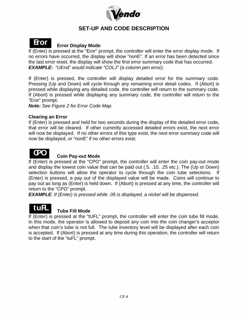
CP-4
SET-UP AND CODE DESCRIPTION
Error Display Mode If (Enter) is pressed at the “Eror” prompt, the controller will enter the error display mode. If no errors have occurred, the display will show ”nonE”. If an error has been detected since the last error reset, the display will show the first error summary code that has occurred. EXAMPLE: “UEnd” would indicate “COLJ” (a column jam error). If (Enter) is pressed, the controller will display detailed error for the summary code. Pressing (Up and Down) will cycle through any remaining error detail codes. If (Abort) is pressed while displaying any detailed code, the controller will return to the summary code. If (Abort) is pressed while displaying any summary code, the controller will return to the “Eror” prompt. Note: See Figure 2 for Error Code Map. Clearing an Error If (Enter) is pressed and held for two seconds during the display of the detailed error code, that error will be cleared. If other currently accessed detailed errors exist, the next error will now be displayed. If no other errors of this type exist, the next error summary code will now be displayed, or “nonE” if no other errors exist. Coin Pay-out Mode If (Enter) is pressed at the “CPO” prompt, the controller will enter the coin pay-out mode and display the lowest coin value that can be paid out (.5, .10, .25 etc.). The (Up or Down) selection buttons will allow the operator to cycle through the coin tube selections. If (Enter) is pressed, a pay out of the displayed value will be made. Coins will continue to pay out as long as (Enter) is held down. If (Abort) is pressed at any time, the controller will return to the “CPO” prompt. EXAMPLE: If (Enter) is pressed while .05 is displayed, a nickel will be dispensed. Tube Fill Mode If (Enter) is pressed at the “tUFL” prompt, the controller will enter the coin tube fill mode. In this mode, the operator is allowed to deposit any coin into the coin changer’s acceptor when that coin’s tube is not full. The tube inventory level will be displayed after each coin is accepted. If (Abort) is pressed at any time during this operation, the controller will return to the start of the “tuFL” prompt.
Eror
CPO
tuFL

CP-5
Error Codes
Summary level error codes (as displayed) Error codes are cleared by pressing the Detailed level error codes ENTER button for 2 sec. when displayed Description or automatically by the following activities:
nonE No errors exist UEnd Vend mechanism summary error
CJXX Column jam in column XX Complete a test cycle for column Ctrl Control system summary error
dS Door Switch Door Closed rAn RAM check sum of service mode settings Change any service mode setting ACLO AC supply low SF Scale factor incompatibility Scale factor corrected IS Machine inlet chute sensor is blocked Blockage removed Ib Machine inlet chute is blocked Coin detected by changer
SEL Selection switch summary error SLXX Selection switch error in switch XX Switch opens
StS Space-to-sales summary error UAXX Unassigned column for column XX Column is assigned
CHAr Changer summary error CC No changer communication Proper communication tS Tube sensor error Changer corrected IC Changer inlet chute blocked A coin is sensed tJXX Tube payout jam in tube XX Changer corrected CrCH Changer ROM check sum error Changer corrected EE Excessive escrow attempts A valid coin is sensed nJ Coin jam A coin is sensed LA Acceptance rate below 80% Acceptance rate improves above 80% dIS Disconnected acceptor Acceptor properly connected rout Coin routing error Coin is routed properly
bUAL Bill validator summary error bC No bill validator communication Proper communication bFUL Bill validator stacker full Receive stacker command bILL Defective bill validator motor Validator becomes enabled bJ Bill validator jammed Validator becomes enabled brCH Bill validator ROM check sum error Validator becomes enabled bOPn Bill validator stacker is open or out of position Validator becomes enabled bS Bill validator sensor error Validator becomes enabled
Crdr Card reader summary error CrC No card reader communication Proper communication CrXY Card reader non-transient error: code X, sub-code Y Error stops being reported
OLn On-line module summary error OC No on-line module communication Proper communication OnC No on-line network communication Proper communication Ol On-line module internal error Resolved by OLM
rUnd Remove vend mechanism (USD) summary error rUca No communication with remote vend mechanism “a” Proper communication rUaX Error X from remote vend mechanism “a” Device specific
S-d Selection/display device (ASD) summary error SdC No selection/display device communication Proper communicaion SdX Error X from selection/display device Device specific
rFrG Refrigeration system summary error SEnS Temperature sensor defective or unplugged Sensor detected COLd Cabinet temperature 3°F below low limit Temperature rises above low limit Hot Cabinet temperature 3°F above high limit Temperature falls below high limit CnPr Cooling system not cooling System cools 1°F per hour Htr Heating system not heating System heats 1°F per hour Figure 2
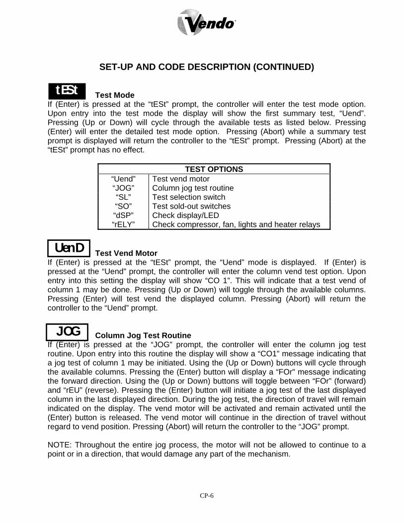
CP-6
SET-UP AND CODE DESCRIPTION (CONTINUED) Test Mode If (Enter) is pressed at the “tESt” prompt, the controller will enter the test mode option. Upon entry into the test mode the display will show the first summary test, “Uend”. Pressing (Up or Down) will cycle through the available tests as listed below. Pressing (Enter) will enter the detailed test mode option. Pressing (Abort) while a summary test prompt is displayed will return the controller to the “tESt” prompt. Pressing (Abort) at the “tESt” prompt has no effect.
TEST OPTIONS “Uend” Test vend motor “JOG” Column jog test routine “SL” Test selection switch “SO” Test sold-out switches “dSP” Check display/LED “rELY” Check compressor, fan, lights and heater relays
Test Vend Motor If (Enter) is pressed at the “tESt” prompt, the “Uend” mode is displayed. If (Enter) is pressed at the “Uend” prompt, the controller will enter the column vend test option. Upon entry into this setting the display will show “CO 1”. This will indicate that a test vend of column 1 may be done. Pressing (Up or Down) will toggle through the available columns. Pressing (Enter) will test vend the displayed column. Pressing (Abort) will return the controller to the “Uend” prompt. Column Jog Test Routine If (Enter) is pressed at the “JOG” prompt, the controller will enter the column jog test routine. Upon entry into this routine the display will show a “CO1” message indicating that a jog test of column 1 may be initiated. Using the (Up or Down) buttons will cycle through the available columns. Pressing the (Enter) button will display a “FOr" message indicating the forward direction. Using the (Up or Down) buttons will toggle between “FOr” (forward) and “rEU” (reverse). Pressing the (Enter) button will initiate a jog test of the last displayed column in the last displayed direction. During the jog test, the direction of travel will remain indicated on the display. The vend motor will be activated and remain activated until the (Enter) button is released. The vend motor will continue in the direction of travel without regard to vend position. Pressing (Abort) will return the controller to the “JOG” prompt. NOTE: Throughout the entire jog process, the motor will not be allowed to continue to a point or in a direction, that would damage any part of the mechanism.
tESt
UenD
JOG
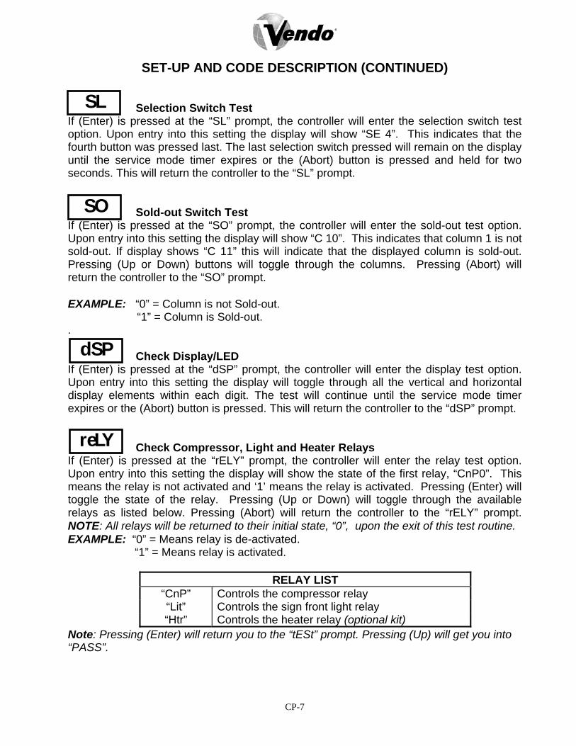
CP-7
SET-UP AND CODE DESCRIPTION (CONTINUED)
Selection Switch Test If (Enter) is pressed at the “SL” prompt, the controller will enter the selection switch test option. Upon entry into this setting the display will show “SE 4”. This indicates that the fourth button was pressed last. The last selection switch pressed will remain on the display until the service mode timer expires or the (Abort) button is pressed and held for two seconds. This will return the controller to the “SL” prompt. Sold-out Switch Test If (Enter) is pressed at the “SO” prompt, the controller will enter the sold-out test option. Upon entry into this setting the display will show “C 10”. This indicates that column 1 is not sold-out. If display shows “C 11” this will indicate that the displayed column is sold-out. Pressing (Up or Down) buttons will toggle through the columns. Pressing (Abort) will return the controller to the “SO” prompt. EXAMPLE: “0” = Column is not Sold-out.
“1” = Column is Sold-out. . Check Display/LED If (Enter) is pressed at the “dSP” prompt, the controller will enter the display test option. Upon entry into this setting the display will toggle through all the vertical and horizontal display elements within each digit. The test will continue until the service mode timer expires or the (Abort) button is pressed. This will return the controller to the “dSP” prompt. Check Compressor, Light and Heater Relays If (Enter) is pressed at the “rELY” prompt, the controller will enter the relay test option. Upon entry into this setting the display will show the state of the first relay, “CnP0”. This means the relay is not activated and ‘1’ means the relay is activated. Pressing (Enter) will toggle the state of the relay. Pressing (Up or Down) will toggle through the available relays as listed below. Pressing (Abort) will return the controller to the “rELY” prompt. NOTE: All relays will be returned to their initial state, “0”, upon the exit of this test routine. EXAMPLE: “0” = Means relay is de-activated.
“1” = Means relay is activated.
RELAY LIST “CnP” Controls the compressor relay “Lit” Controls the sign front light relay “Htr” Controls the heater relay (optional kit)
Note: Pressing (Enter) will return you to the “tESt” prompt. Pressing (Up) will get you into “PASS”.
SL
SO
dSP
reLY

CP-8
SET-UP AND CODE DESCRIPTION (CONTINUED) Password Protection “PASS” will display only if the password has not been entered. The password is entered via the first four selection buttons while the controller is displaying ”PASS”. The password must be entered within 10 seconds in the following order: 4-2-3-1. The display will go blank after the first selection button is pressed. After completing the sequence, press (Enter). If the password is not recognized, the display will remain blank.
Cash Counter Display Mode If (Enter) is pressed at the “CASH” prompt, the controller will enter the non-resettable cash counter mode by displaying “CASH”. Pressing (Enter) will display cash total over the control board’s life. A decimal will be displayed in the appropriate position. Pressing (Up or Down) will change the display to “CA N”/”XXXX” where “N” is a selection number and the “XXXX” will be replaced with the current re-settable cash amount. Using the (Up or Down) will cycle through the available selections. If (Abort) is pressed at anytime during this operation, the controller will return to the “CASH” prompt. Vend Counter Display Mode If (Enter) is pressed at the “SALE” prompt, the controller will enter the non-resettable vend counter display mode by displaying “SALE”. Pressing (Enter) will display the number of all paid vends over the control board’s life. Using (Up or Down) will cycle through each selection as “SL 1”/”0000.” where the “1” indicates the selection and the ‘0’s represent the resettable number of vends for that selection. A decimal will be displayed in the appropriate position. If (Abort) is pressed anytime during this operation, the controller will return to the “SALE” prompt. Selection Price Setting Mode If (Enter) is pressed at the “PrIC” prompt, the controller will enter the selection price setting mode. The display will show “Pr 1” if the machine is in multi-price mode, or “SPrI” if the machine is in single-price mode. In the multi-price mode, individual selection prices can be changed using the (Up or Down) to display “PrXX” where ‘XX’ is the selection number, or choose “ALL” to change the prices for all selection. If (Enter) is pressed, the display will show the current price for the displayed selection. Using (Up or Down) will increase or decrease the price. Holding (Up or Down) for more than five seconds will cause the price to change at 10 times the normal rate. While the desired price is on the display, press (Enter) and it will save that price. Pressing (Abort) will return to the selection level without saving the new price.
CASh
SALE
PrIC
PASS

CP-9
SET-UP AND CODE DESCRIPTION (CONTINUED) Space-to-Sale Programming Mode If (Enter) is pressed at the “StS” prompt, the controller will enter the space-to-sales (StS) programming mode by displaying “OPtX” where ‘X’ is the current option selected. Using (Up or Down) will allow the operator to cycle through the available space-to-sales options “Opt1”- “OPt9” and “CSTS”. When one of the options, “OPt1”-“OPt9”, is on the display, pressing (Enter) will select that space-to-sale option and return to the “STS” prompt. If one of the “OPt1”-“OPt9”option is displayed and (Abort) is pressed, the user will return to the “STS” prompt without changing any settings. NOTE: “OPt1”, ”OPt2”, ”OPt8”, “OPt9” are the only configuration settings recommended. Factory setting is “OPt1”. For proper configuration settings refer to the label located on the inner door shear panel. (See figure 3)
PRE- PROGRAMMED SPACE - TO - SALES
SEL # COLUMNS 1 1,2 1,2 1,2 1,2 1,2,3 1,2,3 1,2 1,2,3 ALL 2 3 1,2 1,2 1,2 1,2,3 1,2,3 3,4 1,2,3 ALL 3 4 3,4 3 1,2 1,2,3 1,2,3 5 4,5 ALL 4 5 5 3 1,2 1,2,3 1,2,3 6 6 ALL 5 6 6 4 3 4 4,5 7 7 ALL 6 7 7 4 4 4 4,5 8 8 ALL 7 8 8 5 5 5 6 9 9 ALL 8 9 9 6 6 6 6 10 10 ALL 9 10 10 7 7 7 7 1,2 1,2,3 ALL 10 ~ ~ 8 8 8 8 ~ ~ ALL 11 ~ ~ 9 9 9 9 ~ ~ ALL 12 ~ ~ 10 10 10 10 ~ ~ ALL 13 ~ ~ 1,2 1,2 1,2,3 1,2,3 ~ ~ ALL
OPTION 1 2 3 4 5 6 7 8 9 Figure 3 Custom Space-to-Sales Mode If (Enter) is pressed at the “CStS” prompt, the controller will enter the custom space-to-sales (CStS) programming mode by displaying “SLXX” where ‘XX’ is the current selection for that certain button, alternating with either “nonE” indicating that no columns are assigned to the displayed selection button or the display will scroll through a sequence of numbers that represents the columns that are currently assigned to the selection button. Using (Up or Down) will cycle through all the available selections and then “SAUE”. Pressing (Abort) will go immediately to the “SAUE” prompt, when pressing the (Abort) button will return the controller to the “CSTS” prompt without changing any settings.
StS
CStS

CP-10
SET-UP AND CODE DESCRIPTION (CONTINUED) Pressing (Enter) while “SAUE” is displayed will save all changes and return the controller to the “STS” prompt. Pressing (Enter) while the “SLXX” prompt is displayed will allow columns to be assigned to the current selection. The display will show “Cnn” where “nn” is a column number. Using (Up or Down) will cycle through all the available columns. Pressing (Enter) at any column will enter the edit mode. The display will show “CnnX” where “X” will either be flashing “0”(disabled) or “1”(enabled) to assign the columns(“nn”) to the current selection. Using (Up or Down) will change the assignment status of the columns. Pressing (Abort) will return the controller to the “Cnn” prompt without changing the status of the column, while pressing (Enter) saves the displayed status of the column before returning to the “Cnn” prompt. Pressing (Abort) at the “CnnX” prompt returns the controller to the “SLXX” prompt. EXAMPLE: “Cnn0” = The selection is disabled. “Cnn1” = The selection is enabled. Machine Configuration Mode If (Enter) is pressed at the “Con” prompt, the controller will enter the machine configuration mode by displaying “C1 X” which indicates configuration options number 1 and the “X” is the current status of that setting. If “X” is 1 then status is active, if “X” is “0” then the status is not active. If (Abort) is pressed while at the “C1 X” prompt the controller will return to the “Con” prompt. Pressing (Up or Down) will toggle through the available configuration options. Pressing (Enter) saves the status of the current option and returns the user to the “Con” prompt. Pressing (Abort) returns the controller to the “Con” prompt without saving. (See Figure 4.) EXAMPLE: “0” = The Con is disabled.
“1” = The Con is enabled.
Single/Multi-Price Mode Toggles between the single-price and multi-price modes. In the single-price mode, the price of selection 1 will be used for all selections. In the multi-price mode, each selection can be set to a different price. “0” = Single pricing is used. “1” = Multi-pricing is used.
Con
C1

CP-11
SET-UP AND CODE DESCRIPTION (CONTINUED)
Optional Feature Enable This selection will allow optional features to be enabled and displayed in the current service mode menu. If any of the optional features described in this document are implemented, they must be able to be hidden by this selection. These features currently include “bLC1”, “bLC2”, “dISC” and “OUEr”. “0” = Option is Off. “1” = Option is On.
CONFIGURATION SETTINGS
C1
C2
C3
C4
C5
C6
C7
C8
C9
C10
CON#
PRICE SETTING
OPTIONAL FEATURES
POS MESSAGE
DOOR OPEN MIS
MIS RESET
RESERVED
SAVE CREDIT
FORCE VEND
MULTI VEND
BILL ESCROW
DESCRIPTION0=SINGLE PRICE
0=DISABLE OPTIONAL PROGRAM
0=DISPLAY POS MESSAGE
0=DISPLAY SUMMARY ERROR CODES
0=RESET MIS VIA DEX COMMAND ONLY1=RESET MIS WHEN DOOR IS CLOSED
0=SAVE CREDIT FOR 5 MINUTES1=SAVE CREDIT INDEFINITELY0=NORMAL VEND1=FORCE VEND0=SINGLE VEND1=MULTI VEND
1=DISABLE BILL ESCROW0=ENABLE BILL ESCROW
1=MULTI PRICE
1=ENABLE OPTIONAL PROGRAM
1=TURN OFF POS MESSAGE
1=DISPLAY SUMMARY SALES DATA
SETTINGS
Figure 4
C2

CP-12
SET-UP AND CODE DESCRIPTION (CONTINUED) LED Display Message Mode Toggles between the LED display modes. In the display/LED mode, the current price will be displayed if in the single price mode. Note: ICE COLD COCA COLA will scroll when the option is set at “0”. “0” = Display message is On. “1” = Display message is Off. Door Open MIS Mode This option changes the Open-Door Mode Display. If enabled, the total machine sales and total machine cash value are displayed before the error codes. These values represent the number of all paid vends and the cash amount of all paid vends, respectively. The sales and cash value are displayed the same as in the “SALE” and “CASH” service mode functions. The display shows “SALE”/”0000”/”0000” for two seconds on the display/LED, then “CASH”/”0000”/”00.00”, then “Eror” or “nonE”. If this option is disabled, existing errors are displayed, or “nonE” for no existing errors. “0” = Existing errors or “nonE” is displayed. “1” = “SALE”/”0000”/”0000” “CASH”/”0000”/”00.00” and “Eror” or “nonE”.
MIS Reset Mode This option is used to allow the door switch to reset all re-settable MIS. It will be reset only if the “CASH” and “SALES” mode were entered.
“0” = All re-settable MIS registers will be reset only when the “CF” command is received from the HHC.
“1” = All re-settable MIS registers are reset when the door switch is activated if any of the re-settable MIS registers are read.
RESERVED FOR FUTURE PROGRAMMING.
C5
C6
C3
C4
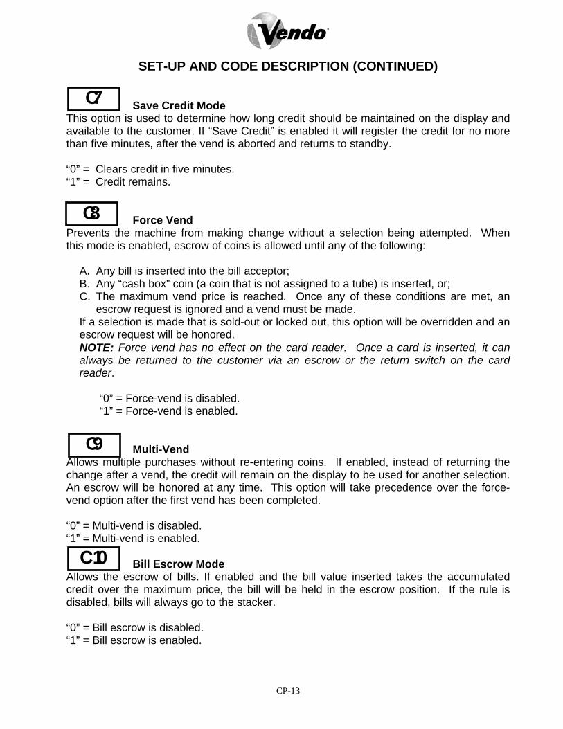
CP-13
SET-UP AND CODE DESCRIPTION (CONTINUED) Save Credit Mode This option is used to determine how long credit should be maintained on the display and available to the customer. If “Save Credit” is enabled it will register the credit for no more than five minutes, after the vend is aborted and returns to standby. “0” = Clears credit in five minutes. “1” = Credit remains. Force Vend Prevents the machine from making change without a selection being attempted. When this mode is enabled, escrow of coins is allowed until any of the following:
A. Any bill is inserted into the bill acceptor; B. Any “cash box” coin (a coin that is not assigned to a tube) is inserted, or; C. The maximum vend price is reached. Once any of these conditions are met, an
escrow request is ignored and a vend must be made. If a selection is made that is sold-out or locked out, this option will be overridden and an escrow request will be honored. NOTE: Force vend has no effect on the card reader. Once a card is inserted, it can always be returned to the customer via an escrow or the return switch on the card reader.
“0” = Force-vend is disabled. “1” = Force-vend is enabled.
Multi-Vend Allows multiple purchases without re-entering coins. If enabled, instead of returning the change after a vend, the credit will remain on the display to be used for another selection. An escrow will be honored at any time. This option will take precedence over the force-vend option after the first vend has been completed. “0” = Multi-vend is disabled. “1” = Multi-vend is enabled. Bill Escrow Mode Allows the escrow of bills. If enabled and the bill value inserted takes the accumulated credit over the maximum price, the bill will be held in the escrow position. If the rule is disabled, bills will always go to the stacker. “0” = Bill escrow is disabled. “1” = Bill escrow is enabled.
C9
C 10
C7
C8

CP-14
SET-UP AND CODE DESCRIPTION (CONTINUED) Correct Change Only Control Allows the customer to disable or enable the overpay routine. If “Con0”, Consumer overpay routine disabled for USA. If “Con1”, Can be enabled for International use. If “CCU”, “Correct Change Value” is the value that the controller has the ability to control
the “Use Correct Change Only” option. If “ACC”, “Unconditional Acceptance Value” is the largest value of any single form of
currency that can be accepted without knowledge that the equivalent value of coins can be returned. This option applies to coins or bills.
Preview Vend Password Setting Mode If (Enter) is pressed at the “PrEV” prompt, the controller will display the current password for the preview vend mode. The first digit of the number will be flashing. Pressing (Up or Down) will adjust the currently flashing digit up or down. Pressing (Enter) will save the currently flashing digit and the next digit of the password will begin flashing. All digits may be modified in this manner. Pressing (Enter) while the last digit is flashing saves the currently displayed password and return to the “PrEV” prompt. Pressing (Abort) at any time in the procedure returns to the “PrEV” prompt without saving. Change Language If (Enter) is pressed at the “LAnG” prompt, the controller will display the current language for the preview mode. Pressing (Up or Down) will toggle through the available languages listed below. Pressing (Enter) will activate the displayed language and return to the ”LAnG” prompt. Pressing (Abort) at any time in the procedure returns to the controller to the “LAnG” prompt without changing the active language.
LANGUAGE LIST “EnG” English - mandatory if supported “Frn” French - mandatory if supported “Ger” German - mandatory if supported “ItA” Italian - mandatory if supported
“Port” Portuguese - mandatory if supported “ESP” Spanish - mandatory if supported “SLO” Slovene - mandatory if supported
LAnG
CCOC
PrEU

CP-15
SET-UP AND CODE DESCRIPTION (CONTINUED) Time/Date Setting Mode If (Enter) is pressed at the “tinE” (time) prompt, the controller will enter the time/date setting mode and display “Enb0” (disable) or “Enb1” (enable). Using (Up or Down) will allow the controller to cycle through all available time selection options. If (Abort) is pressed anytime during this operation, the controller will return to the “tInE” prompt.
TIME SELECTION OPTIONS “Enb1” Enable/Disable time (Edit mode 0/1) “YEAr” Current Year (Example ’98) “dAtE” Current Date (month, day) “nth” Current Month
“hour” Current Time (hours, minutes) “dSt” Daylight Saving Time
Year Setting Option If (Enter) is pressed at the “YEAr” prompt, the last two digits of the year are displayed and will be flashing. Pressing (Up or Down) will increase or decrease the year setting. Pressing (Enter) will save the displayed year setting and return the user to “YEAr”. Pressing (Abort) will return to “YEAr” without saving. Month Setting Option If (Enter) is pressed at the “nth” prompt, the controller will enter the month setting option. Upon entry into this option the display will show the current two-digit month setting, indicating the month of the year (example: 01-12). Pressing (Up or Down) will increase or decrease the month setting. Pressing (Enter) will save the displayed month setting and return the Controller to the “nth” prompt. Pressing (Abort) while the month digits are flashing returns to the “nth” prompt without saving the month. Date Setting Option If (Enter) is pressed at the “dATE” prompt, the current two-digit date (days of the month) is displayed. Pressing (Up or Down) will increase or decrease the date setting. Pressing (Enter) will save the displayed date and return the user to the “datE” prompt. Pressing (Abort) while the date digits are flashing returns to the “datE” prompt without saving the new date.
dATE
tIne
YeAr
nth
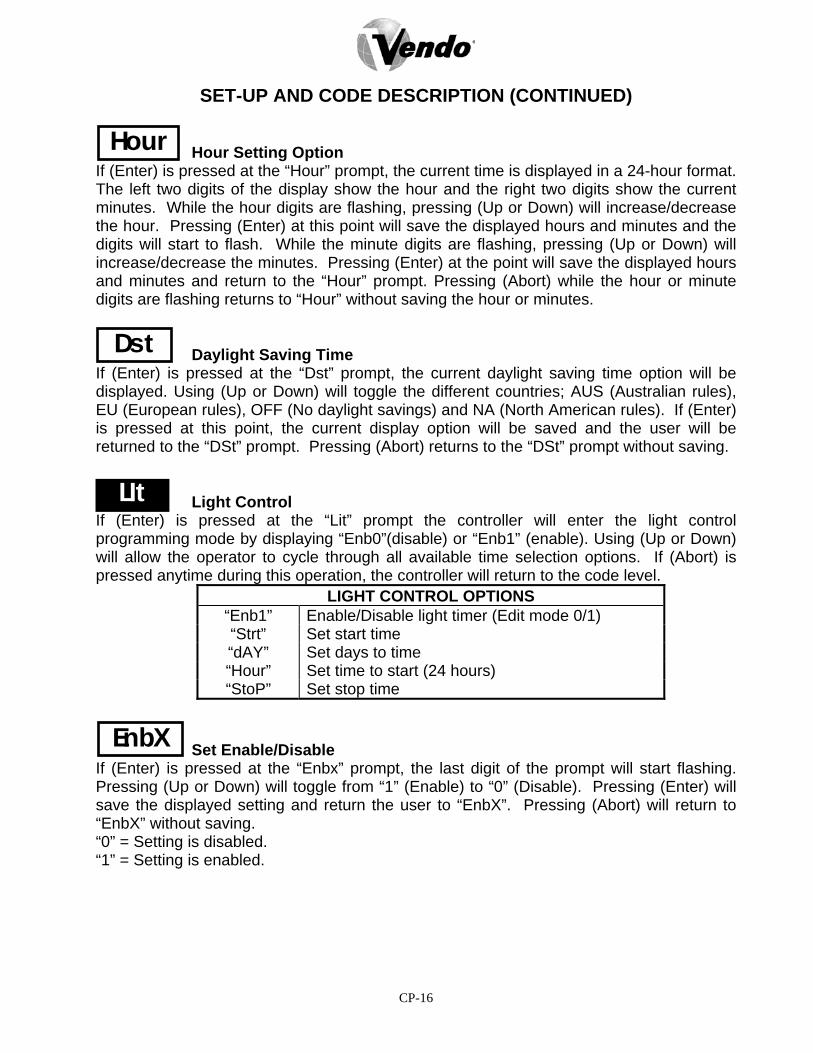
CP-16
SET-UP AND CODE DESCRIPTION (CONTINUED) Hour Setting Option If (Enter) is pressed at the “Hour” prompt, the current time is displayed in a 24-hour format. The left two digits of the display show the hour and the right two digits show the current minutes. While the hour digits are flashing, pressing (Up or Down) will increase/decrease the hour. Pressing (Enter) at this point will save the displayed hours and minutes and the digits will start to flash. While the minute digits are flashing, pressing (Up or Down) will increase/decrease the minutes. Pressing (Enter) at the point will save the displayed hours and minutes and return to the “Hour” prompt. Pressing (Abort) while the hour or minute digits are flashing returns to “Hour” without saving the hour or minutes. Daylight Saving Time If (Enter) is pressed at the “Dst” prompt, the current daylight saving time option will be displayed. Using (Up or Down) will toggle the different countries; AUS (Australian rules), EU (European rules), OFF (No daylight savings) and NA (North American rules). If (Enter) is pressed at this point, the current display option will be saved and the user will be returned to the “DSt” prompt. Pressing (Abort) returns to the “DSt” prompt without saving. Light Control If (Enter) is pressed at the “Lit” prompt the controller will enter the light control programming mode by displaying “Enb0”(disable) or “Enb1” (enable). Using (Up or Down) will allow the operator to cycle through all available time selection options. If (Abort) is pressed anytime during this operation, the controller will return to the code level.
LIGHT CONTROL OPTIONS “Enb1” Enable/Disable light timer (Edit mode 0/1) “Strt” Set start time “dAY” Set days to time “Hour” Set time to start (24 hours) “StoP” Set stop time
Set Enable/Disable If (Enter) is pressed at the “Enbx” prompt, the last digit of the prompt will start flashing. Pressing (Up or Down) will toggle from “1” (Enable) to “0” (Disable). Pressing (Enter) will save the displayed setting and return the user to “EnbX”. Pressing (Abort) will return to “EnbX” without saving. “0” = Setting is disabled. “1” = Setting is enabled.
Hour
Dst
LIt
EnbX
CP-17
SET-UP AND CODE DESCRIPTION (CONTINUED) Start Time Setting If (Enter) is pressed at the “Strt” prompt, the controller will enter the start time setting option. Upon entry into this option the display will show “dAY”. Pressing (Up or Down) will cycle through the available summary level codes. Pressing (Enter) will enter the detail level option. Pressing (Abort) while a summary level prompt is displayed will return the controller to the “Strt” prompt. Pressing (Abort) at the “Strt” prompt will return the controller to the “Lit” prompt. Day Setting Option If (Enter) is pressed at the “dAY” prompt, the current day of the week is displayed. The days are displayed as follows: “nonX” Monday “tuEX” Tuesday “WEdX” Wednesday “thuX” Thursday “FriX” Friday “SAtX” Saturday “SunX” Sunday “ALL” All Days “0” = Setting is disabled. “1” = Setting is enabled. Pressing (Up or Down) at this point will rotate through the days of the week. Pressing (Enter) when a day (e.g. nonX) is displayed the “X” will start to flash by pressing (Up or Down) will toggle from “0” (disable) to “1” (enable). If (Enter) is pressed, the displayed day is saved and the user is returned to “dAY” prompt. Pressing (Abort) returns the controller to “dAY” prompt without saving. Start Hour Setting If (Enter) is pressed at the “Hour” prompt, the current time is displayed in a 24-hour format. The left two digits of the display will show the hour and the right two digits show the current minutes. While the hour digits are flashing, pressing (Up or Down) will increase/decrease the hour. Pressing (Enter) at this point will save the displayed hours and minutes and the digits will start to flash. While the minute digits are flashing, press (Up or Down) to increase/decrease the minutes. Pressing (Enter) at this point will save the displayed hours and minutes and return to the “Hour” Prompt. Pressing (Abort) while the hour or minutes digits are flashing returns to “Hour” without saving.
Strt
dAY
Hour

CP-18
SET-UP AND CODE DESCRIPTION (CONTINUED) Set Stop If (Enter) is pressed at the “StoP” prompt, the controller will enter the stop time setting option. Upon entry into this option the display will show “dAtE”. Pressing (Up or Down) will cycle through the available summary level codes. Pressing (Enter) will enter the detail level option. Pressing (Abort) while a summary level prompt is displayed will return the controller to the “StoP” prompt. Pressing (Abort) at the “StoP” prompt will return the controller to the “Lit” prompt. Note: To program days and hours refer to page CP-15. Refrigeration Control Mode If (Enter) is pressed at the “rFrG” prompt, the controller will enter the refrigeration control option by displaying “EnbX” indicating the enable/disable setting mode. Using (Up or Down) will allow the operator to toggle between the following modes:
REFRIGERATION CONTROL OPTIONS “EnbX” Enable/Disable Refrigeration timer (Edit mode 0/1) “Strt” Set start time “dAY” Set days to time “Hour” Set time to start (24 hours) “StoP” Set stop time “dAY” Set days to time “Hour” Set time to start (24 hours)
Temperature Setting If (Enter) is pressed at the “rFrG” prompt, the controller will enter the refrigeration control option by displaying “EnbX” indicating the enable/disable setting mode. Using (Up or Down) will allow the operator to toggle between the following modes:
TEMPERATURE SETTING OPTIONS “dEGX” Set Temperature (Edit mode Fahrenheit/Celsius) “SEtP” Temperature set point (Factory setting 35ºF 1.5ºC) “Stor” Storage temperature setting (Factory setting 60º F 15.5ºC)
“dSP0” POS temperature display (Edit mode 0/1) Degree Setting If (Enter) is pressed at the “dEGX” prompt, the controller will display “dEGX” where ‘X’ will be ‘F’ if the controller is currently in ºF (Fahrenheit) mode or ‘C’ if the controller is currently in ºC (Celsius) mode. Pressing (Up or Down) while the “X” digit is flashing will toggle the ‘X’ digit between ‘F’ and ‘C’. Pressing (Enter) will save the displayed temperature mode and return the user to the “dEGX” prompt. Pressing (Abort) will return to the “dEGX” prompt without saving.
rFrG
dEGX
StoP

CP-19
SET-UP AND CODE DESCRIPTION (CONTINUED) Set Point Setting (35ºF) If (Enter) is pressed at the “SEtP” prompt, the controller will display “XX.Xt” where ‘X’ will be the current set point temperature. Pressing (Up or Down) will increase/decrease by one degree increments. Pressing (Enter) will save the displayed temperature setting and return the user to the “SEtP” prompt. Pressing (Abort) will return to the “SEtP” prompt without saving. Storage Temperature Setting (60ºF) If (Enter) is pressed at the “Stor” prompt, the controller will display “XX.Xt” where ‘X’ will be the current storage temperature. Pressing (Up or Down) will increase/decrease by one degree increments. Pressing (Enter) will save the displayed storage temperature setting and return the user to the “Stor” prompt. Pressing (Abort) will return to the “Stor” prompt without saving. Display Temperature If (Enter) is pressed at the “dSP0” prompt, the controller will enter into the LED temperature display enable option. Upon entry into this option the display will show the current setting “dSP0” where the “0” is flashing will disable the temperature from being shown in the LED or if “1” is flashing the temperature will be displayed in the LED following “ICE COLD COCA COLA”. Pressing (Up or Down) will toggle the digit between ‘0’ and ‘1’. Pressing (Enter) will save the currently displayed setting and return the user to the “dSP0” prompt. Pressing (Abort) will return to the “dSP0” prompt without saving. Block Selection Setting If (Enter) is pressed at the “bLC1” or “bLC2” prompt, the controller will enter the second bank of selection blocking control option. Upon entry into this routine the display will show the first summary level code “Enb0”. Pressing (Enter) will save the currently displayed setting and return the user to the “bLC1” prompt. Pressing (Abort) will return to the “bLC1” prompt without saving. Using (Up or Down) will let the operator toggle between the following modes: Note: “BLC1” will not be accessible when “C2” is set at “0”. “0” = Block option is disabled. “1” = Block option is enabled.
dSP0
BLC 1
SEtP
Stor
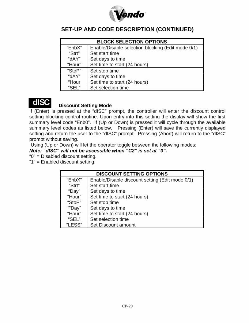
CP-20
SET-UP AND CODE DESCRIPTION (CONTINUED)
BLOCK SELECTION OPTIONS “EnbX” Enable/Disable selection blocking (Edit mode 0/1) “Strt” Set start time “dAY” Set days to time “Hour” Set time to start (24 hours) “StoP” Set stop time “dAY” Set days to time “Hour Set time to start (24 hours) “SEL” Set selection time
Discount Setting Mode If (Enter) is pressed at the “dISC” prompt, the controller will enter the discount control setting blocking control routine. Upon entry into this setting the display will show the first summary level code “Enb0”. If (Up or Down) is pressed it will cycle through the available summary level codes as listed below. Pressing (Enter) will save the currently displayed setting and return the user to the “dISC” prompt. Pressing (Abort) will return to the “dISC” prompt without saving. Using (Up or Down) will let the operator toggle between the following modes: Note: “dISC” will not be accessible when “C2” is set at “0”. “0” = Disabled discount setting. “1” = Enabled discount setting.
DISCOUNT SETTING OPTIONS “EnbX” Enable/Disable discount setting (Edit mode 0/1) “Strt” Set start time “Day” Set days to time “Hour” Set time to start (24 hours) “StoP” Set stop time “”Day” Set days to time “Hour” Set time to start (24 hours) “SEL” Set selection time
“LESS” Set Discount amount
dISC

CP-21
SET-UP AND CODE DESCRIPTION (CONTINUED)
Selection Setting If (Enter) is pressed at the “SEL” prompt, the controller will enter the selection setting option. Upon entry into this setting the display will show the current setting for selection as “01 1”, where “1” shows it is enabled or “0” if the option is disabled. If (Up or Down) is pressed it will cycle through the valid selections or “ALL”. Pressing (Enter) will save the currently displayed setting and return the controller to the “SEL” prompt. Pressing (Abort) will return the controller to the “SEL” prompt without saving. “0” = Selection setting is disabled. “1” = Selection setting is enabled. Selection Setting If (Enter) is pressed at the “LESS” prompt, the controller will enter the discount amount option. Upon entry into this setting the display will show the current four digit discount amount. If (Up or Down) is pressed it will increase or decrease the lowest discount amount. Pressing (Enter) will save the currently displayed setting and return the user to the “LESS” prompt. Pressing (Abort) will return to the “LESS” prompt without saving. Over-Ride Option Mode (Units equipped with optional key switch) If (Enter) is pressed at the “OUEr” prompt, the controller will enter the over-ride option. Upon entry into this setting the display will show the first summary level code “FrEX”. If (Up or Down) is pressed it will cycle through the available summary level codes as listed below. Pressing (Enter) will save the currently displayed setting and return the user to the “OUEr” prompt. Pressing (Abort) will return to the “OUEr” prompt without saving. Using (Up or Down) will let the operator toggle between the following modes: “0” = Disabled over-ride option. “1” = Enabled over-ride option. Note: “OUEr” will not be accessible when “C2” is set at “0”.
OVERRIDE SETTING OPTIONS “FrE0” Enable/Disable free vend (Edit mode 0/1) “Und0” Enable/Disable No vend “bLC0” Selection blocking over-ride “dSC0” Discounting over-ride “Lit0” Lighting control over-ride
“FrG0” Refrigeration control over-ride
SET-UP AND CODE DESCRIPTION (CONTINUED)
OUEr
SEL
LESS
CP-22
Over-Ride Free Vend If (Enter) is pressed at the “FrE0” prompt, the controller will enter the free vend enable option. Upon entry into this setting the display will show the current setting “FrE0”. Pressing (Up or Down) will toggle between ‘0’(disable) or ‘1’(enable). Pressing (Enter) will save the currently displayed setting and return the user to the “FrE0” prompt. Pressing (Abort) will return to the “FrE0” prompt without saving. “0” = Disabled free vend. “1” = Enabled free vend. Over-Ride No Vend If (Enter) is pressed at the “Und0” prompt, the controller will enter the no vend (vend over-ride) enable routine. Upon entry into this setting the display will show the current setting “Und0”. Pressing (Up or Down) will toggle between ‘0’ (disable) or ‘1’ (enable). While enabled, selections will not be allowed to vend and a “nO SALE” message will be displayed. NOTE: If both the “free vend” and “no vend” features are enabled, the “no vend” will be given priority. Over-Ride Selection Blocking If (Enter) is pressed at the “bLC0” prompt, the controller will enter the selection blocking over-ride enable option. Upon entry into this setting the display will show the current setting “bLC0”. Pressing (Up or Down) will toggle between ‘0’ (disable) or ‘1’ (enable). Pressing (Enter) will save the currently displayed setting and return the user to the “bLC0” prompt. Pressing (Abort) will return to the “bLC0” prompt without saving. “0” = Disabled selection blocking. “1” = Enabled selection blocking. Over-Ride Discount If (Enter) is pressed at the “dSC0” prompt, the controller will enter the discounting over-ride enable option. Upon entry into this setting the display will show the current setting “dSC0”. Pressing (Up or Down) will toggle between ‘0’ (disable) or ‘1’ (enable). Pressing (Enter) will save the currently displayed setting and return the user to the “dSC0” prompt. Pressing (Abort) will return to the “dSC0” prompt without saving. “0” = Disabled discount over-ride. “1” = Enabled discount over-ride.
FrE0
Blc0
dSC0
Und0

CP-23
SET-UP AND CODE DESCRIPTION (CONTINUED) Over-Ride Lighting Control If (Enter) is pressed at the “Lit0” prompt, the controller will enter the lighting control over-ride enable option. Upon entry into this setting the display will show the current setting “Lit0”. Pressing (Up or Down) will toggle between ‘0’ (disable) or ‘1’ (enable). Pressing (Enter) will save the currently displayed setting and return the user to the “Lit0” prompt. Pressing (Abort) will return to the “Lit0” prompt without saving. “0” = Disabled lighting control. “1” = Enabled lighting control.
Over-Ride Refrigeration Control If (Enter) is pressed at the “FrG0” prompt, the controller will enter the refrigeration control over-ride enable option. Upon entry into this setting the display will show the current setting “FrG0”. Pressing (Up or Down) will toggle between ‘0’ (disable) or ‘1’ (enable). Pressing (Enter) will save the currently displayed setting and return the user to the “FrG0” prompt. Pressing (Abort) will return to the “FrG0” prompt without saving. “0” = Disabled refrigeration control over-ride. “1” = Enabled refrigeration control over-ride. Remote Vend Mechanism – Reserved for future technology
LIt0
FrG0
rUnd

CP-24
VEC 10 WIRING DIAGRAM (COCA-COLA)

CP-25
VEC 10 WIRING DIAGRAM (CONTINUED)
WHT
WHT
2
BLK1
OR
110 VOLT AUXILIARY PLUG
110VAC
WHT32
BLK1
110VAC
WHT
BLK
220VAC
WHTSNA
BLK
GRN
RT
WHT
23
BLK1
(110 VOLTCAPACITOR
COMPRESSOR
VIO
GRN
DOOR
CABINET
8
WHTBLK
GRN
YELVIO
ORNGRY
121
WHTBLKBLU
ORNBRNWHTREDPNKGRY
4
REDWHTBLKSHLD
YEL 1
1
DOOR
CABINET
SENSORTEMP
REFRIG
OPTIONAL
BLK WHT
SLOW BLOW0.8 AMP
FUSE
BLKBLK
GRY
LIGHT
YEL
RELAY
BLK
EMI
FILTERNOISE
BLK
TRANSFORMER
WHT
24VAC
BLK
ORN
HEATER
GRY
RELAY
VIO GRY
RELAY
PLAIN
WHT
BLK or BLU
WHT
BLKPOWERSWITCH
BLK
RIBBED
ORNWHT
WHT or BRN
RIBBED PLAIN
OVERLOAD
PLUG
MOTORSEVAP. FAN
M
OPTIONAL
BLK BLK
BLK WHT
HEATEROPTIONAL
21BLK
BLK
WHT
ORN
PLAIN
21
21
21RIBBED
NC
WHTCOM
SWITCHDOOR
WHT
RELAYSTART
ONLY) M
GRN or GRN/YEL
MOTORCOND. FAN
PLAIN
UNITS
RIBBED
SEE NEXT PAGEFOR VEND MOTORS
AND SOLD-OUT SWITCHESHARNESS DIAGRAM
BRN

CP-26
VEC 10 WIRING DIAGRAM (CONTINUED)
WHTWHTWHT
WHTWHT
WHTWHT
WHTWHT
WHTWHT
WHTWHT
WHTWHT
WHT
VEND MOTORS & SOLD-OUT SWITCHES
MOTOR # 1
NOCOM
MOTOR # 2MOTOR # 3MOTOR # 4MOTOR # 5MOTOR # 6MOTOR # 7MOTOR # 8MOTOR # 9MOTOR # 10
CABINET
DOOR
DOOR
CABINET
MOTOR # 10 MOTOR # 9 MOTOR # 8 MOTOR # 7 MOTOR # 6 MOTOR # 5 MOTOR # 4 MOTOR # 3 MOTOR # 2
1
MOTOR # 1
PINS 1&4: 12VDC MOTOR ACTIVATE / SWITCH MONITOR CIRCUIT (2X5 MATRIX)
NRO
OIV
NRB
LEY P
NK
PNK
PNK
PNK L
EY
KNP
NRB
OIV
NRO
YRG
ULB
ULB
ULB
ULB
YRG
ULB
RED
LB
K
PINS 5&6: 24VDC MOTOR DRIVE CIRCUIT (DAISY CHAIN)
MOTOR # 1MOTOR # 2MOTOR # 3MOTOR # 4MOTOR # 5MOTOR # 6MOTOR # 7MOTOR # 8MOTOR # 9MOTOR # 10
6
WH
WH
TT
WHTWHT
NOCOM
23
556K
BL
DER
56K
BL
DER
56K
BL
DER
56K
BL
DER
56K
BL
DER
56K
BL
DER
56K
BL
DER
56K
BL
DER
56K
BL
DER
44 14 14 14 14 14 14 14 14 1
PINS 2&3: 0 VDC SOLDOUT SWITCH TO MOTOR BOARD (EXTENSION OF 2X5 MATRIX)TYPICAL
SOLDOUT SWITCH
V-MAX MOTOR HARNESS SCHEMATIC BREAKDOWN

CP-27
VEC 10 WIRING DIAGRAM (MINI V-MAX)
VEND MOTORS & SOLD-OUT SWITCHES
MOTOR # 1MOTOR # 2MOTOR # 3MOTOR # 4MOTOR # 5MOTOR # 6MOTOR # 7MOTOR # 8
CABINET
DOOR
DOOR
CABINET
SOLD OUT SWITCH
PINS 1 & 4: 12VDC MOTOR ACTIVATE / SWITCH MONITOR
MOTOR # 1MOTOR # 2MOTOR # 3MOTOR # 4MOTOR # 5MOTOR # 6MOTOR # 7MOTOR # 8
CABINET
DOOR
DOOR
CABINET
RED
BLU
WH
WH
TTLB
K
RED
BLU
WH
WH
TTLB
K
RED
BLU
WH
WH
TTLB
K
RED
WH
WH
TT
GRY
LB
K
RED
WH
WH
TT
ORN
LB
K
RED
WH
WH
TT
VIO
LB
K
RED
WH
WH
TT
BRN
LB
K
RED
PNK
WH
WH
TT
YEL
LB
KKNP
KNP
KNP
KNPY
EL
BRN
VIO
PINS 5 & 6 : 24VDC MOTOR DRIVE CIRCUIT (DAISY CHAIN)
MOTOR #
11111111
MOTOR # 2MOTOR # 3MOTOR # 4MOTOR # 5MOTOR # 6MOTOR # 7MOTOR # 8
66666666
CABINET
DOOR
DOOR
CABINET

CP-28
NOTES
1. If the outer door is left open for over an hour, the lights and compressor will become active. In order to override this option just press the door switch one time.

C-1 8/2002
CABINET PARTS SECTION
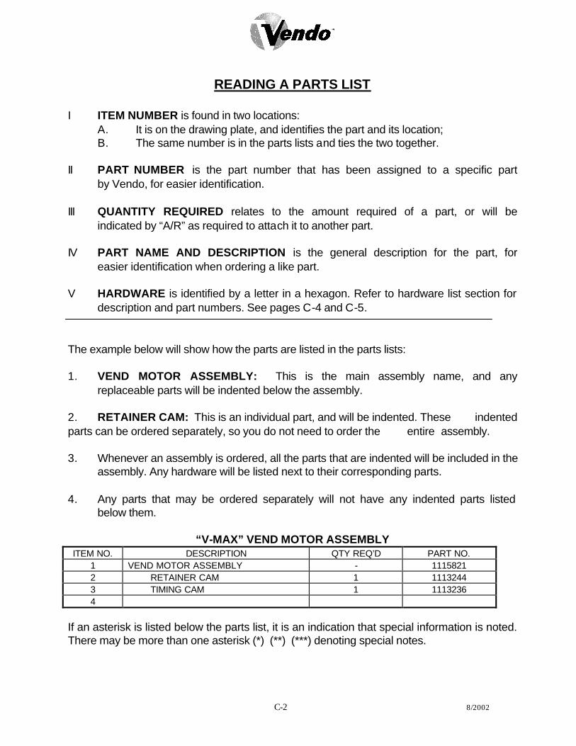
C-2 8/2002
READING A PARTS LIST
I ITEM NUMBER is found in two locations: A. It is on the drawing plate, and identifies the part and its location; B. The same number is in the parts lists and ties the two together. II PART NUMBER is the part number that has been assigned to a specific part by Vendo, for easier identification. III QUANTITY REQUIRED relates to the amount required of a part, or will be indicated by “A/R” as required to attach it to another part. IV PART NAME AND DESCRIPTION is the general description for the part, for easier identification when ordering a like part. V HARDWARE is identified by a letter in a hexagon. Refer to hardware list section for
description and part numbers. See pages C-4 and C-5. The example below will show how the parts are listed in the parts lists: 1. VEND MOTOR ASSEMBLY: This is the main assembly name, and any replaceable parts will be indented below the assembly. 2. RETAINER CAM: This is an individual part, and will be indented. These indented parts can be ordered separately, so you do not need to order the entire assembly. 3. Whenever an assembly is ordered, all the parts that are indented will be included in the
assembly. Any hardware will be listed next to their corresponding parts. 4. Any parts that may be ordered separately will not have any indented parts listed below them.
“V-MAX” VEND MOTOR ASSEMBLY ITEM NO. DESCRIPTION QTY REQ’D PART NO.
1 VEND MOTOR ASSEMBLY - 1115821 2 RETAINER CAM 1 1113244 3 TIMING CAM 1 1113236 4
If an asterisk is listed below the parts list, it is an indication that special information is noted. There may be more than one asterisk (*) (**) (***) denoting special notes.
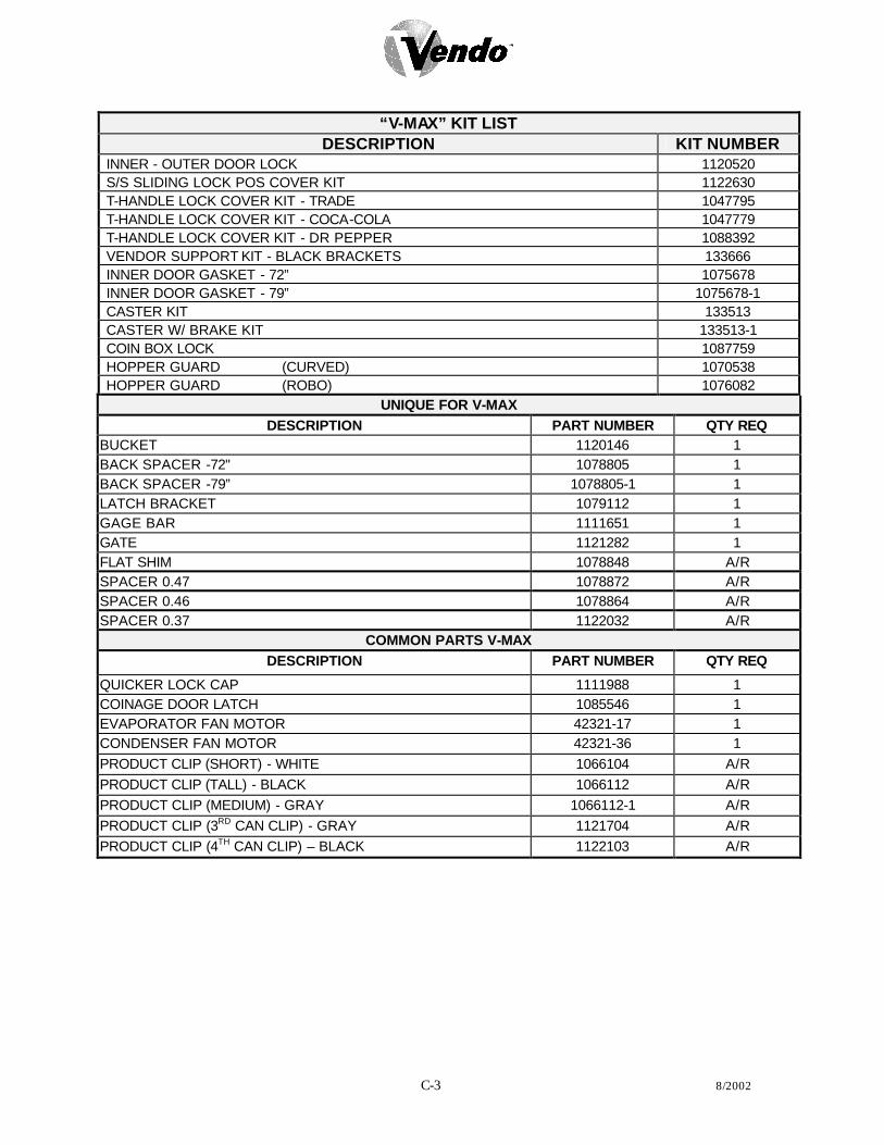
C-3 8/2002
“V-MAX” KIT LIST
DESCRIPTION KIT NUMBER INNER - OUTER DOOR LOCK 1120520 S/S SLIDING LOCK POS COVER KIT 1122630 T-HANDLE LOCK COVER KIT - TRADE 1047795 T-HANDLE LOCK COVER KIT - COCA-COLA 1047779 T-HANDLE LOCK COVER KIT - DR PEPPER 1088392 VENDOR SUPPORT KIT - BLACK BRACKETS 133666 INNER DOOR GASKET - 72” 1075678 INNER DOOR GASKET - 79” 1075678-1 CASTER KIT 133513 CASTER W/ BRAKE KIT 133513-1 COIN BOX LOCK 1087759 HOPPER GUARD (CURVED) 1070538 HOPPER GUARD (ROBO) 1076082
UNIQUE FOR V-MAX DESCRIPTION PART NUMBER QTY REQ
BUCKET 1120146 1 BACK SPACER -72" 1078805 1 BACK SPACER -79” 1078805-1 1 LATCH BRACKET 1079112 1 GAGE BAR 1111651 1 GATE 1121282 1 FLAT SHIM 1078848 A/R SPACER 0.47 1078872 A/R SPACER 0.46 1078864 A/R SPACER 0.37 1122032 A/R
COMMON PARTS V-MAX DESCRIPTION PART NUMBER QTY REQ
QUICKER LOCK CAP 1111988 1 COINAGE DOOR LATCH 1085546 1 EVAPORATOR FAN MOTOR 42321-17 1 CONDENSER FAN MOTOR 42321-36 1 PRODUCT CLIP (SHORT) - WHITE 1066104 A/R PRODUCT CLIP (TALL) - BLACK 1066112 A/R PRODUCT CLIP (MEDIUM) - GRAY 1066112-1 A/R PRODUCT CLIP (3RD CAN CLIP) - GRAY 1121704 A/R PRODUCT CLIP (4TH CAN CLIP) – BLACK 1122103 A/R

C-4 8/2002
Hardware List

C-5 8/2002
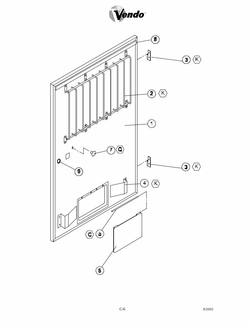
C-6 8/2002

C-7 8/2002
V-MAX INNER DOOR ASSEMBLY
ITEM MODEL NUMBER GIV 576 720 840 NO. DESCRIPTION QTY
REQ PART NO. PART NO. PART NO. PART NO.
1 INNER DOOR ASSEMBLY (FOAMED) 1 134302-54 134302-53 134302-44 134302-47 2 PROD. RETAINER UPPER 1 1120633-4 1117937 1120633-4 1120633-5 3 HINGE - FEMALE 2 1121286 1121286 1121286 1121286 4 PROD. DEFLECTOR 2 1120129 1120129 1120129 1120129 5 PIN - HINGE 1 389985 389985 389985 389985 6 FLAP - DOOR (REVERSIBLE) 1 1013076 1013076 1013076 1013076 7 KNOB - DOOR 1 388305 388305 388305 388305 8 RAIN SEAL - INNER DOOR 1 1111732-2 1111732-2 1111732-2 1111732-2 9 GROMMET 2 388090 388090 388090 388090
THE FOLLOWING ARE NOT SHOWN ~ LABEL - PRODUCT SET-UP GUIDE 1 1122196 1122196 1122196 1122196 ~ LABEL - 9.2 ERROR CODE MAP 1 1111465 1111465 1111465 1111465 ~ LABEL - PROGRAMMING VEC 9.2 1 1111244 1111244 1111244 1111244 ~ LABEL –WIRING DIAGRAM VEC 9.2 1 1122839 1122839 1122839 1122839 ~ LABEL – WARNING 1 1008323-1 1008323-1 1008323-1 1008323-1 ~ LABEL – CONFIGURATION MAP 1 1111457 1111457 1111457 1111457 ~ LABEL – SPACE TO SALES 1 1123367 1123367 1123367 1123367

C-8 8/2002
4
25
3
2
22
1
7
5
6 10 11
9
8
19
13
18 17
16 15 14 24
21
23
20
P Y
AD AA
S
P
K
AM
K
B
K
AC
K
P
26
28
27
29 P
30

C-9 8/2002
V-MAX CABINET ASSEMBLY ITEM NO.
DESCRIPTION QTY REQ
PART NO.
1 CABINET ASSEMBLY - FOAMED 1 * 2 CLOSURE BRACKET 2 1078791 3 HINGE PIN 1 389071 4 RAMP 1 1120387 5 AIR DAM - RIGHT 1 1122548 6 LEVELING LEG 4 1059902 7 CONDENSATE PAN 1 1122475 8 DRAIN TUBE 1 1088449 9 NUT - DRAIN TUBE 1 387925 10 FOAM WASHER 1 387837 11 DRAIN TUBE FUNNEL 1 1068678 12 BRACKET - REFRIGERATION 2 388387 13 QUICKER LOCK ASSEMBLY 1 2010085-04 14 LATCH BRACKET 1 1079112 15 NUT RETAINER HOUSING 1 389022 16 NUT SEGMENT 3 1001477 17 SPRING 1 389690 18 CAP 1 1111988 19 SIDE DECAL 2 ** 20 REAR STACK SUPPORT BRACKET 1 1079015 21 AIR BAFFLE - CABINET 1 1068023 22 TOP HINGE ASSEMBLY 1 2000805-03 23 BACKING PLATE 1 1120667 24 FRONT STACK SUPPORT BRACKET 2 1079007 25 AIR DAM ASSEMBLY (SEE PGS C16-C17) 1 -- 26 PRODUCT CHUTE ASSEMBLY 1 1121926 ~ PRODUCT CHUTE ASSEMBLY (MODEL 576) 1 1121926-1 27 DOOR SWITCH BRACKET 1 1121043 28 DOOR SWITCH 1 323007 29 OVERLAPPING DOOR GUARD - 72” 1 2001376 ~ OVERLAPPING DOOR GUARD - 79” 1 2002325 30 FIBERGLASS EVAPORATION BOARD 1 1122728 31 AIR DAM BRACKET (NOT SHOWN) 1 1112112 32 LOWER HINGE BRACKET (NOT SHOWN) 1 1121924
*NOTE: WHEN ORDERING CABINET ASSEMBLY, PLEASE PROVIDE 9-CODE OR 11-CODE AND MANUFACTURER’S DATE CODE.
**NOTE: WHEN ORDERING DECALS, PLEASE PROVIDE STYLE.

C-10 8/2002
5
1
2
6
4
3
7
J
F
J
8
9

C-11 8/2002
V-MAX STACK ASSEMBLY
ITEM MODEL NUMBER GIV 576 720 840 512/680 603/800 NO. DESCRIPTION QTY
REQ PART NO. PART NO PART NO. PART NO. PART NO. PART NO.
1 STACK CHASSIS ASSEMBLY 1 1112694-01 1112694-03 1112694-01 1112694-02 1005219-102 1005219-103 2 MECH COVER 1 1076634 1117724 1076634 1076634 1076634 1076634 3 BACK SPACER ASSEMBLY 10 2009473-01 2009473-01 2009473-01 2009473 2009473-02 2009473-03 4 HOOK RACK RETAINER 2 1086813 1086813 1086813 1086813 1086813 1086813 5 LOADING RACK / PRODUCT
RETAINER 1 1086805-1 1117848 1086805-1 1086805-1 1086805-1 1086805-1
6 BRKT - LOADING RACK 3 1120095 1120095 1120095 1120095 1120095 1120095 7 MOTOR HARNESS 1 1120138 1117856 1120138 1120138 1120138 1120138 8 HANGER -TOP 1 1120489 1120489 1120489 1120489 1120489 1120489 9 HANGER - BOTTOM 1 1120490 1120490 1120490 1120490 1120490 1120490

C-12 8/2002
6
5
4
26
22
21
20
14
9 8
10
19 22
24 23
25
7
11 12
13
15
3
2
1
18
17 16
27
28 29
11
13
28
12
29
I

C-13 8/2002
V-MAX STACK ASSEMBLY
ITEM MODEL NUMBER GIV 576 720/840 NO. DESCRIPTION QTY
REQ PART NO. PART NO. PART NO.
1 VEND MOTOR ASSEMBLY 10 1115821 1115821 1115821 2 RETAINER - CAM 1 1113244 1113244 1113244 3 TIMING CAM 1 1113236 1113236 1113236 4 SPRING 10 390326 390326 390326 5 SWITCH - SOLD-OUT 10 368299 368299 368299 6 SWITCH MOUNT - SOLD-OUT 10 1120037 1120037 1120037 7 FRONT MECH PLATE 1 1079023 1117678 1079023 8 SOLD-OUT LEVER - LONG 10 1112163 1112163 1112163 9 ANTI THEFT CLIP 40 389712 389712 389712 10 VEND BUCKET 10 1120146 1120146 1120146 11 * CLIP - SEE PRODUCT SET-UP GUIDE
(SHORT - WHITE) AR 1066104 1066104 1066104
12 * CLIP - SEE PRODUCT SET UP GUIDE (MEDIUM - GREY)
AR 1066112-1 1066112-1 1066112-1
13 * CLIP - SEE PRODUCT SET-UP GUIDE (TALL - BLACK)
AR 1066112 1066112 1066112
14 GAGE BAR 10 1111651 1111651 1111651 15 * PRODUCT SPACER - FLAT .06 AR 1078848 1078848 1078848 16 *PRODUCT SPACER - 0.27 AR 1122032 1122032 1122032 17 * PRODUCT SPACER - 0.37 AR 1078864 1078864 1078864 18 * PRODUCT SPACER - 0.47 AR 1078872 1078872 1078872 19 COTTER CLIP - GAGE BAR 10 387450 387450 387450 20 GATE 10 1121282 1121282 1121282 21 BEARING - GATE (FRONT & REAR) 20 385603-5 385603-5 385603-5 22 E-CLIP - GATE 20 388589 388589 388589 23 SPRING 10 387849 387849 387849 24 GATE LINK 10 1120140 1120140 1120140 25 BUSHING - VEND BUCKET (FRONT & REAR) 20 1008706 1008706 1008706 26 MOTOR COUPLING 10 1076465 1076465 1076465 27 COTTER CLIP - SPACER 1 1032526 1032526 1032526 28 FOUR-DEEP CLIP AR 1122103 1122103 1122103 29 3RD CAN CLIP AR 1121704 1121704 1121704
* NOTE: DEPENDING ON PRODUCT SET-UP ** NOTE: ALL 576 MODELS WILL ONLY HAVE EIGHT COMPONENTS
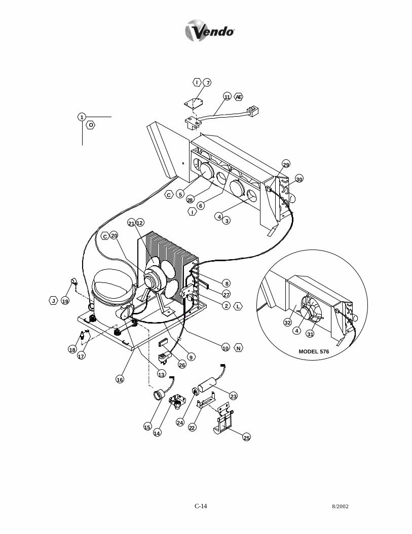
C-14 8/2002
11 AE
C 5
1
7 I
O
3
29
C
30
I 4
6 28
20
21 12
2 27
L
8
MODEL 576
31 4 32
N 10
26 9
23
22
16 13
14
17
15
J 19
18
24
25

C-15 8/2002
V-MAX REFRIGERATION ASSEMBLY ITEM NO.
DESCRIPTION QTY REQ
110V PART NO.
1 REFRIGERATION ASSEMBLY D90 1 1120341 2 SERVICE PLUG ASSEMBLY US 1 1120617 3 FAN CLIP - EVAPORATOR 2 336640 4 FAN BLADE 2 1113562 5 EVAPORATOR FAN MOTOR 2 42321-17 6 ORIFICE PLATE - EVAPORATOR FAN 1 1120571 7 BRACKET TEMP SENSOR 1 1121777 8 CLAMP PUSH MOUNT 1 384692-3 9 COMPRESSOR CORD 1 1121020
10 BRACKET - CONDENSER FAN 1 389797 11 TEMP SENSOR 1 1121777 12 FAN CLIP - CONDENSER 1 V42323 13 BASE - REFRIGERATION 1 1122470 14 START RELAY (INCLUDED IN ASSEMBLY 513506066) 1 -- 15 OVERLOAD PROTECTOR (INCLUDED IN ASSEMBLY 513506066) 1 -- 16 COVER – OVERLOAD (INCLUDED IN ASSEMBLY 513506066) 1 -- 17 CLIP - COMPRESSOR MOUNT 4 336640 18 STUD COMPRESSOR MOUNT 4 390102 19 CLAMP 1 324099-3 20 FAN MOTOR - CONDENSER 1 42321-36 21 FAN BLADE - CONDENSER 1 320766 22 BRACKET – CAPACITOR (INCLUDED IN ASSEMBLY 1112805) 1 -- 23 CAPACITOR (INCLUDED IN ASSEMBLY 1112805) 1 -- 24 END CAP – CAPACITOR (INCLUDED IN ASSEMBLY 1112805) 1 -- 25 CLIP - CAPACITOR 1 1076481 26 EDGE TRIM - SHORT 3 388304-1 27 EDGE TRIM - LONG 1 388304-3 28 BRACKET - FAN MOTOR 1 389797 29 EVAPORATOR HARNESS 1 1122193 30 EVAPORATOR 1 385470 31 EVAPORATOR FAN BRACKET MOUNT 3 1117996 32 ORIFICE PLATE- EVAPORATOR FAN (SINGLE) 1 390228

C-16 8/2002
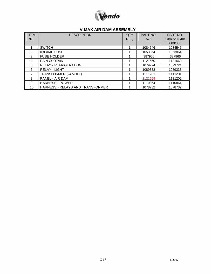
C-17 8/2002
V-MAX AIR DAM ASSEMBLY ITEM NO.
DESCRIPTION QTY REQ
PART NO. 576
PART NO. GIV/720/840/
680/800 1 SWITCH 1 1084546 1084546 2 0.8 AMP FUSE 1 1053864 1053864 3 FUSE HOLDER 1 387966 387966 4 RAIN CURTAIN 1 1121660 1121660 5 RELAY - REFRIGERATION 1 1079724 1079724 6 RELAY - LIGHT 1 1089333 1089333 7 TRANSFORMER (24 VOLT) 1 1111201 1111201 8 PANEL - AIR DAM 1 1121659 1121202 9 HARNESS - POWER 1 1110864 1110864 10 HARNESS - RELAYS AND TRANSFORMER 1 1078732 1078732

C-18 8/2002
NOTES

CC-1 8/2002
PARTS SECTION COCA - COLA

CC-2 8/2002
16
15
4 K
3
2 D
16
15
1 14
9 13 F
12 YR
11 S Y
U 10
9 13 F
8 R Y
7
6 AE
K5
18
17 AN

CC-3 8/2002
V-MAX COCA-COLA MAIN DOOR
ITEM MODEL NUMBER 720 840 NO. DESCRIPTION QTY REQ PART NO. PART NO.
1 OUTER DOOR – 9 SELECT 1 * * 2 EYELET TRIM 1 388271 388271 3 SIGN FACE 1 ** ** 4 SIGN TRIM - LEFT 1 388125-2B 388125B 5 SIGN CAP - UPPER 1 1114341 1114341 6 RAIN GUARD 1 2000848 2000848 7 DOOR FRAME WELD 1 1121220 1121221 8 DOOR GUARD 1 2010131 2009503 9 SIGN TRIM RIGHT (TOP - BOTTOM) 2 1084538 1084538-1
10 DBV PLUG 1 2001228 2001228 11 LOCK ASSEMBLY (SEE PAGES CC-8 - CC-9) 1 ~ ~ 12 SELECTION PANEL (SEE PAGES CC-6 - CC-7) 1 ~ ~ 13 SIGN TRIM RETAINER 2 1084589 1084589-1 14 SIGN CAP BOTTOM 1 1114341-1 1114341-1 15 FLAT WASHER 3/8” 3 V801491 V801491 16 BUSHING 2 388094 388094 17 ROLLER 1 1120388 1120388 18 BRACKET ROLLER 1 1120552 1120552
*NOTE: WHEN ORDERING DOOR ASSEMBLY. PLEASE PROVIDE 9-CODE OR 11-CODE AND
MANUFACTURER’S DATE CODE. **NOTE: WHEN ORDERING SIGN FACE, PLEASE PROVIDE STYLE.

CC-4 8/2002
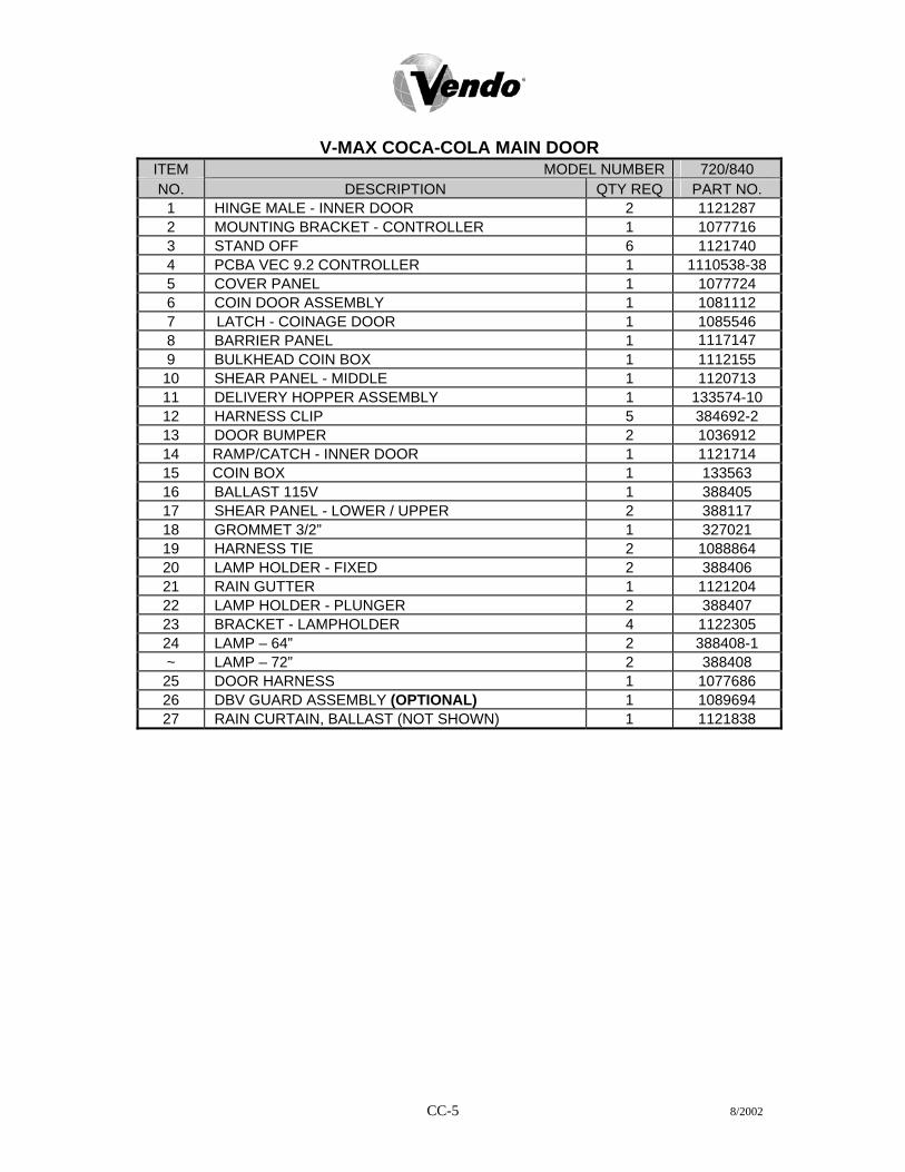
CC-5 8/2002
V-MAX COCA-COLA MAIN DOOR
ITEM MODEL NUMBER 720/840 NO. DESCRIPTION QTY REQ PART NO.
1 HINGE MALE - INNER DOOR 2 1121287 2 MOUNTING BRACKET - CONTROLLER 1 1077716 3 STAND OFF 6 1121740 4 PCBA VEC 9.2 CONTROLLER 1 1110538-38 5 COVER PANEL 1 1077724 6 COIN DOOR ASSEMBLY 1 1081112 7 LATCH - COINAGE DOOR 1 1085546 8 BARRIER PANEL 1 1117147 9 BULKHEAD COIN BOX 1 1112155
10 SHEAR PANEL - MIDDLE 1 1120713 11 DELIVERY HOPPER ASSEMBLY 1 133574-10 12 HARNESS CLIP 5 384692-2 13 DOOR BUMPER 2 1036912 14 RAMP/CATCH - INNER DOOR 1 1121714 15 COIN BOX 1 133563 16 BALLAST 115V 1 388405 17 SHEAR PANEL - LOWER / UPPER 2 388117 18 GROMMET 3/2” 1 327021 19 HARNESS TIE 2 1088864 20 LAMP HOLDER - FIXED 2 388406 21 RAIN GUTTER 1 1121204 22 LAMP HOLDER - PLUNGER 2 388407 23 BRACKET - LAMPHOLDER 4 1122305 24 LAMP – 64” 2 388408-1 ~ LAMP – 72” 2 388408 25 DOOR HARNESS 1 1077686 26 DBV GUARD ASSEMBLY (OPTIONAL) 1 1089694 27 RAIN CURTAIN, BALLAST (NOT SHOWN) 1 1121838

CC-6 8/2002
28
U 25
24 30
D 6
8
27
R Y 5 4
3 U 2
1
7
U
23 22
21
D U 20
U 19
15U
18 17
16 U
14
13 12
U1110
29
9
26 U

CC-7 8/2002
V-MAX COCA-COLA SELECTION PANEL ITEM NO.
DESCRIPTION QTY REQ
PART NO.
~ SELECTION PANEL ASSY. 1 1112643-01 1 DBV COLLAR 1 2001201 2 COIN INSERT - DECAL 1 1044885 3 PLUG - DBV 1 2001228 4 DECORATIVE PANEL - 9-SELECT 1 1029576-5 5 OVERLAY PANEL - 9-SELECT 1 1122713-4 6 PANEL CAP - TOP 1 388139 7 PANEL CAP - BOTTOM 1 388140 8 COVER PANEL 1 1122419 9 SELECTION PANEL 1 2001716
10 BUTTON - COIN RETURN 1 1050473 11 GUIDE PLATE - COIN INSERT/RETURN 1 1050481 12 LENS - DISPLAY 1 1039652 13 PCB - DIGITAL DISPLAY - ELECTRONIC 1 1089678 14 DISPLAY HARNESS 1 1111252 15 SELECTION HARNESS - 9-SELECT 1 1111279 16 CARRIER STRIP ASSEMBLY 1 1017845 17 SWITCH SELECTION 9 368299 18 SWITCH MOUNT 1 1120827 19 COIN RETURN CUP ASSEMBLY 1 1079546 20 PLUG - CROWN PULLER 1 1044737 21 BUTTON SELECTION 9 1016741 22 BUTTON HOUSING (BUSHING) 9 1016768 23 SPRING SELECTION 9 1029959 24 DRAIN TUBING 1 1110619 25 TRAY WATER COLLECTION 1 1110562 26 COIN CHUTE ASSEMBLY 1 1087961 27 COIN CHUTE 1 1002333 28 COVER CHUTE 1 1002341 29 RETAINER - POS LABEL 2 1110155 30 BRACKET – DBV (POS) (OPTIONAL) 1 1089716 31 POS BACKING PLATE (NOT SHOWN) 1 1122389 32 MDB HARNESS (NOT SHOWN) 1 1089341

1
1 7
5 6
2
4 3
10
14 1112
69
8
17
18
1416
15E
D AB
CC-8 8/2002

V-MAX COCA-COLA LOCK ASSEMBLY
ITEM NO.
DESCRIPTION QTY REQ
PART NO.
1 T-HANDLE LOCK ASSEMBLY – ROBO DOOR 1 1114422 -- T-HANDLE LOCK ASSEMBLY - LANDSCAPE 1 1002635 2 T-HANDLE 1 1002392 3 PIN - STUD 1 387601 4 LOCK STUD - QUICKER LOCK 1 1049724 5 SPRING 1 1111554 6 E-RING RETAINER 3 388589 7 HEX WASHER 1 387600 8 SPRING - HEAVY 1 389690 9 FLAT WASHER 1 387718
10 FLANGE 1 1002384 11 LOCK STUD COVER 1 1122126 12 WASHER ½” 2 V801023 13 VAPOR SEAL 1 388132 14 BUSHING (BEARING MECH) 2 385603-4 15 LEVER - COIN RETURN 1 1052619 16 CRANK - COIN RETURN LEVER 1 1002244 17 PIVOT BRACKET - COIN RETURN 1 1002252 18 SPRING - COIN RETURN LEVER 1 1060023
CC-9

NOTES
CC-10

MDC-1 8/2002
MARKETING VENDOR PARTS SECTION
COCA - COLA
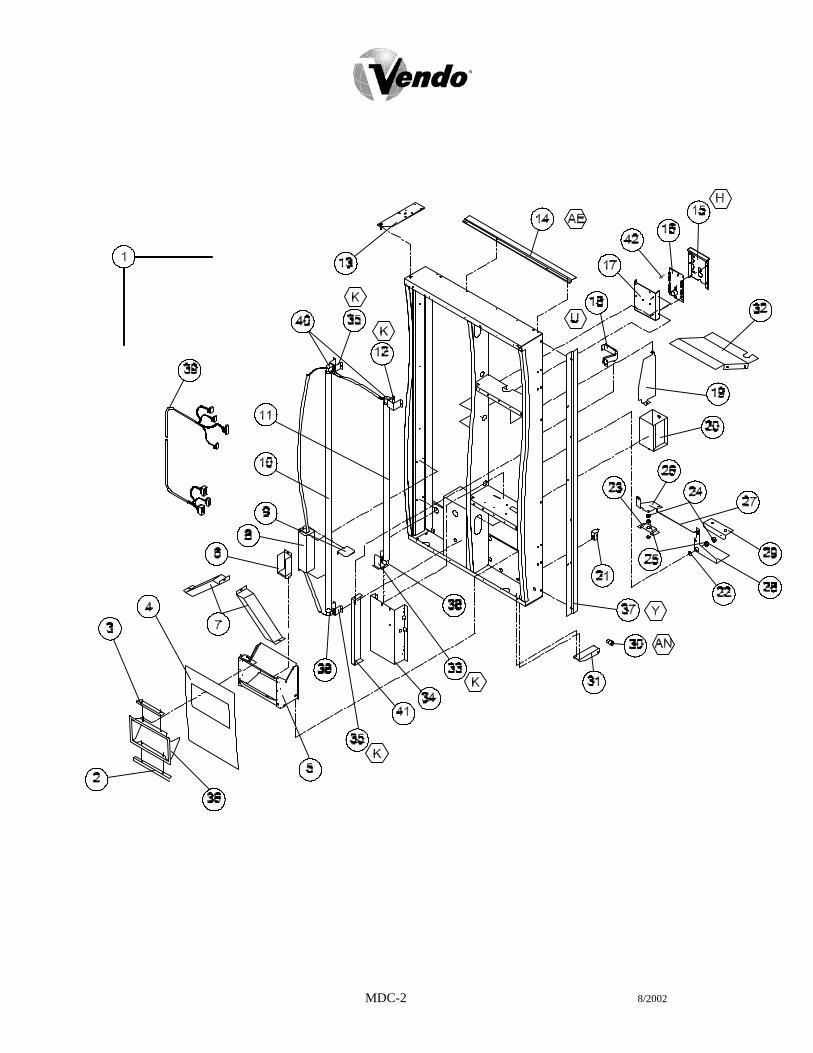
MDC-2 8/2002

MDC-3 8/2002
MARKETING VENDOR COCA-COLA MAIN DOOR
ITEM MODEL NUMBER 603/800 512/680 NO. DESCRIPTION QTY
REQ PART NO. PART NO.
1 OUTER DOOR - 13-SELECT 1 * * 2 BRACKET - LOWER EYELET 1 1118813 1118813 3 BRACKET - UPPER EYELET 1 1118805 1118805 4 SUB-PANEL (HOPPER GRAPHIC) 1 1120059 1120059 5 HOPPER ASSEMBLY 1 1120063 1120063 6 COIN RETURN CUP 1 1120067 1120067 7 PASS CHUTE ASSEMBLY 2 1120068 1120068 8 BALLAST 1 388405 388405 9 RAIN SHIELD - BALLAST 1 1118503 1118503
10 LAMP - 64” / 72” 1 388408 388408-1 11 LAMP - 48” 1 1115643 1115643 12 BRACKET - LAMP HOLDER - UPPER 1 1120354 1120354 13 TOP HINGE PLATE 1 1113007 1113007 14 RAIN GUARD 1 2010174 2010174 15 COVER 1 1077724 1077724 16 VEC 9.2 BOARD CONTROLLER 1 1110538-38 1110538-38 17 BRACKET - VEC MOUNTING 1 1077716 1077716 18 COIN INSERT CHUTE 1 1119686 1119686 19 DBV BARRIER PANEL 1 1120123 1120123 20 COIN BOX ASSEMBLY 1 1120060 1120060 21 INNER DOOR RAMP 1 1016962 1016962 22 WASHER 1 389026 389026 23 PIVOT BRACKET - CRANK 1 1120643 1120643 24 BUSHING 2 1116634 1116634 25 BEARING 2 385603-6 385603-6 26 CRANK 1 1120642 1120642 27 LINK - CRANK 1 1120026 1120026 28 LEVER 1 1120647 1120647 29 PIVOT BRACKET 1 1120028 1120028 30 ROLLER 1 1120388 1120388 31 BRACKET ROLLER 1 1120552 1120552 32 BULKHEAD - MIDDLE 1 1122307 1122307 33 BRACKET - LAMPHOLDER - LOWER 1 1115562 1121418 34 COINAGE DOOR ASSEMBLY 1 1120054 1120054 ~ LATCH - COINAGE DOOR (NOT SHOWN) 1 1085546 1085546 35 BRACKET LAMP - LEFT 2 1119228 1119228 36 EYELET TRIM HOPPER RED 1 1120046 1120046 37 DOOR GUARD 1 2010177 2010177-1 38 LAMP HOLDER - FIXED 2 388406 388406 39 DOOR HARNESS 1 1077686 1077686 40 LAMP HOLDER - PLUNGER 2 388407 388407 41 BULKHEAD - COINAGE 1 1119562 1119562 42 STAND OFF 6 1121740 1121740

MDC-4 8/2002
*NOTE: WHEN ORDERING DOOR ASSEMBLY. PLEASE PROVIDE 9-CODE OR 11-CODE AND MANUFACTURER’S DATE CODE.

MDC-5 8/2002
MARKETING VENDOR COCA-COLA MAIN DOOR ITEM MODEL NUMBER 603/800 512/680 NO. DESCRIPTION QTY REQ PART NO. PART NO.
1 TRIM - BOTTOM 1 1119015-1 1119015-1 2 TRIM - HINGE SIDE 1 1119011 1119011-1 3 PLATE- SIGN TRIM - SIDES 2 1115387 1120125 4 TRIM - TOP 1 1120109 1120109 5 PLATE - TRIM TOP AND BOTTOM 2 1120032 1120032 6 PLATE - SIGN TRIM - CENTER 1 1115380 1120053 7 TRIM - CENTER 1 1114033 1114033-1 8 TRIM - MODULE 2 1119015 1119015 9 PLATE - TRIM MODULE 2 1120127 1120127
10 DOOR WELD 1 2010169 2010169-1 11 SHEAR PANEL - LOWER 1 388117 388117 12 FLAT WASHER 3/8” - BOTTOM 2 V801491 V801491 13 BUSHING 2 388094 388094 14 TRIM - RIGHT 1 1119010-2 1119010-3 15 SIGN FACE - “BOTTLE ON ICE” 1 ** ** 16 COIN BOX GUARD ASSEMBLY 1 1121509 1121509 17 LOCK STUD GUIDE 1 1121356 1121356
**NOTE: WHEN ORDERING SIGN FACE, PLEASE PROVIDE STYLE.

MDC-6 8/2002
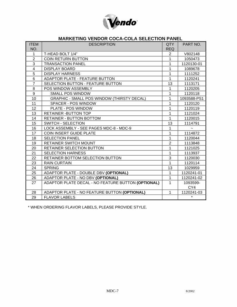
MDC-7 8/2002
MARKETING VENDOR COCA-COLA SELECTION PANEL
ITEM NO.
DESCRIPTION QTY REQ
PART NO.
1 T-HEAD BOLT 1/4” 2 V802148 2 COIN RETURN BUTTON 1 1050473 3 TRANSACTION PANEL 1 1120130-01 4 DISPLAY BOARD 1 1089678 5 DISPLAY HARNESS 1 1111252 6 ADAPTOR PLATE - FEATURE BUTTON 1 1120241 7 SELECTION BUTTON - FEATURE BUTTON 13 1113171 8 POS WINDOW ASSEMBLY 1 1120205 9 SMALL POS WINDOW 1 1120118 10 GRAPHIC - SMALL POS WINDOW (THIRSTY DECAL) 1 1093588-PS111 SPACER - POS WINDOW 1 1120120 12 PLATE - POS WINDOW 1 1120119 13 RETAINER -BUTTON TOP 1 1121024 14 RETAINER - BUTTON BOTTOM 1 1120015 15 SWITCH - SELECTION 13 1114791 16 LOCK ASSEMBLY - SEE PAGES MDC-8 - MDC-9 1 ~ 17 COIN INSERT GUIDE PLATE 1 1114872 18 SELECTION PANEL 1 1120044 19 RETAINER SWITCH MOUNT 2 1113848 20 RETAINER SELECTION BUTTON 1 1121025 21 SELECTION HARNESS 1 1113937 22 RETAINER BOTTOM SELECTION BUTTON 3 1120030 23 RAIN CURTAIN 1 1120114 24 SPRING 13 1029959 25 ADAPTOR PLATE - DOUBLE DBV (OPTIONAL) 1 1120241-01 26 ADAPTOR PLATE - NO DBV (OPTIONAL) 1 1120241-02 27 ADAPTOR PLATE DECAL - NO FEATURE BUTTON (OPTIONAL) 1 1093599-
CY4 28 ADAPTOR PLATE - NO FEATURE BUTTON (OPTIONAL) 1 1120241-03 29 FLAVOR LABELS *
* WHEN ORDERING FLAVOR LABELS, PLEASE PROVIDE STYLE.

2 3
4 5
6 7
10 8
913
1112
1
1
AO Y
MDC-8 8/2002

MARKETING VENDOR COCA-COLA LOCK ASSEMBLY ITEM NO.
DESCRIPTION QTY REQ
PART NO.
1 T-HANDLE LOCK ASSEMBLY 1 1119236 2 T-HANDLE 1 1116732 3 PIN - STUD 1 387601 4 LOCK STUD 1 1114945 5 SPRING 1 389691 6 E-RING RETAINER 1 388589 7 HEX WASHER 1 387600 8 SPRING - HEAVY 1 389690 9 FLAT WASHER 1 387718
10 FLANGE 1 1116724 11 WASHER 1 V801023 12 VAPOR SEAL 1 388132 13 E-RING RETAINER 2 388589 ~ GUARD - T-HANDLE LOCK ASSEMBLY (NOT SHOWN) 1 1119554
MDC-9

MDC-10

MARKETING VENDOR COCA-COLA INNER DOOR ASSEMBLY
ITEM MODEL NUMBER 603/800 512/680 NO. DESCRIPTION QTY
REQ PART NO. PART NO.
1 INNER DOOR ASSEMBLY (FOAMED) 1 134302-52 134302-51 2 HINGE - FEMALE 2 1121286 1121286 3 PROD. RETAINER UPPER 1 1117562-03 1120633-2 4 PIN - HINGE 1 389985 389985 5 FLAP - DOOR (REVERSIBLE) 1 1013076 1013076 6 KNOB - DOOR 1 388305 388305 7 RAIN SEAL - INNER DOOR 1 1111732 1111732 8 GROMMET 2 388090 388090 ~ LABEL - PRODUCT SET-UP GUIDE (NOT SHOWN) 1 1122196 1122196 ~ LABEL - ERROR CODE MAP (NOT SHOWN) 1 1111465 1111465 ~ LABEL - PROGRAMMING VEC 9.2 (NOT SHOWN) 1 1111244 1111244 ~ LABEL - WIRING DIAGRAM (NOT SHOWN) 1 1122839 1122839 ~ LABEL – CONFIGURATION MAP (NOT SHOWN) 1 1111457 1111457 ~ LABEL – SPACE TO SALES (NOT SHOWN) 1 1123367 1123367 ~ SEAL - INNER DOOR (NOT SHOWN) 1 1075678-1 1075678
MDC-11
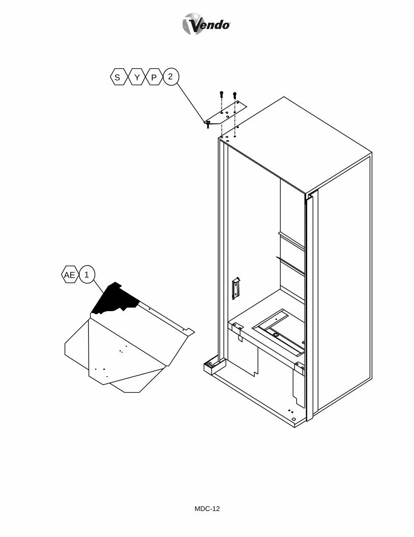
2P Y S
1 AE
MDC-12

MARKETING VENDOR COCA-COLA CABINET ASSEMBLY ITEM NO.
DESCRIPTION QTY REQ
PART NO.
1 PRODUCT CHUTE ASSEMBLY 1 2008643-03 2 TOP HINGE - RED 1 2000805-000
MDC-13

NOTES
MDC-14

SCC-1 8/2002
PARTS SECTION MINI V-MAX
COCA - COLA

SCC-2 8/2002
16
15
4 K
3
2 D
16
15
1
9 13 F
12 YR
11 S Y
U10
9 13 F
8 R Y
7
6 AE
K5
14
18
AN 17
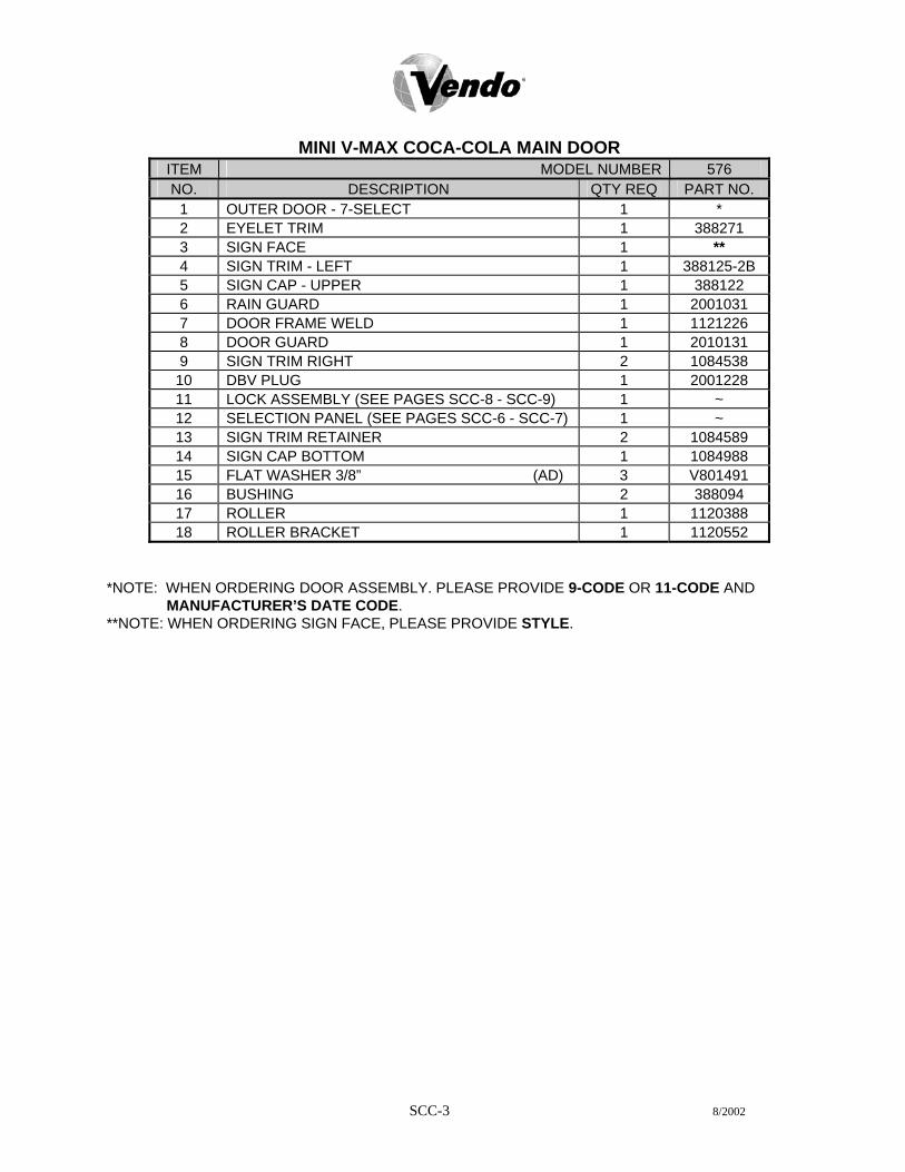
SCC-3 8/2002
MINI V-MAX COCA-COLA MAIN DOOR
ITEM MODEL NUMBER 576 NO. DESCRIPTION QTY REQ PART NO.
1 OUTER DOOR - 7-SELECT 1 * 2 EYELET TRIM 1 388271 3 SIGN FACE 1 ** 4 SIGN TRIM - LEFT 1 388125-2B 5 SIGN CAP - UPPER 1 388122 6 RAIN GUARD 1 2001031 7 DOOR FRAME WELD 1 1121226 8 DOOR GUARD 1 2010131 9 SIGN TRIM RIGHT 2 1084538
10 DBV PLUG 1 2001228 11 LOCK ASSEMBLY (SEE PAGES SCC-8 - SCC-9) 1 ~ 12 SELECTION PANEL (SEE PAGES SCC-6 - SCC-7) 1 ~ 13 SIGN TRIM RETAINER 2 1084589 14 SIGN CAP BOTTOM 1 1084988 15 FLAT WASHER 3/8” (AD) 3 V801491 16 BUSHING 2 388094 17 ROLLER 1 1120388 18 ROLLER BRACKET 1 1120552
*NOTE: WHEN ORDERING DOOR ASSEMBLY. PLEASE PROVIDE 9-CODE OR 11-CODE AND
MANUFACTURER’S DATE CODE. **NOTE: WHEN ORDERING SIGN FACE, PLEASE PROVIDE STYLE.

SCC-4 8/2002

SCC-5 8/2002
MINI V-MAX COCA-COLA MAIN DOOR ITEM MODEL NUMBER 576 NO. DESCRIPTION QTY REQ PART NO.
1 DOOR WELD - 72” 1 1121226 2 HINGE - INNER DOOR, MALE 2 1121287 3 MOUNTING BRACKET - CONTROLLER 1 1077716 4 STAND OFF 7 1121740 5 PCBA VEC 9.2 CONTROLLER 1 1110538-38 6 COVER PANEL 1 1077724 7 COIN DOOR ASSEMBLY 1 1081112 8 LATCH - COINAGE DOOR 1 1085546 9 BARRIER PANEL 1 1117147
10 BULKHEAD COIN BOX SUPPORT 1 1112155 11 SHEAR PANEL - MIDDLE 1 1120713-1 12 DELIVERY HOPPER 1 133574-10 13 HARNESS CLIP 5 384692-2 14 DOOR BUMPER 2 1036912 15 RAMP/CATCH - INNER DOOR 1 1121714 16 COIN BOX 1 133563 17 BALLAST 115V- HO 1 388405 18 SHEAR PANEL - LOWER 1 389624 19 GROMMET 3/2” 1 327021 20 HARNESS TIE 2 1088864 21 LAMP HOLDER - FIXED 2 388406 22 RAIN GUTTER 1 1121204 23 LAMP HOLDER - PLUNGER 2 388407 24 BRACKET - LAMPHOLDER 4 1122305 25 LAMP – 64” 2 388408-1 26 DOOR HARNESS 1 1077686 27 DBV GUARD ASSEMBLY (OPTIONAL) 1 1089694 28 SAIL PANEL 2 388774 29 RAIN CURTAIN BALLAST (NOT SHOWN) 1 1121838
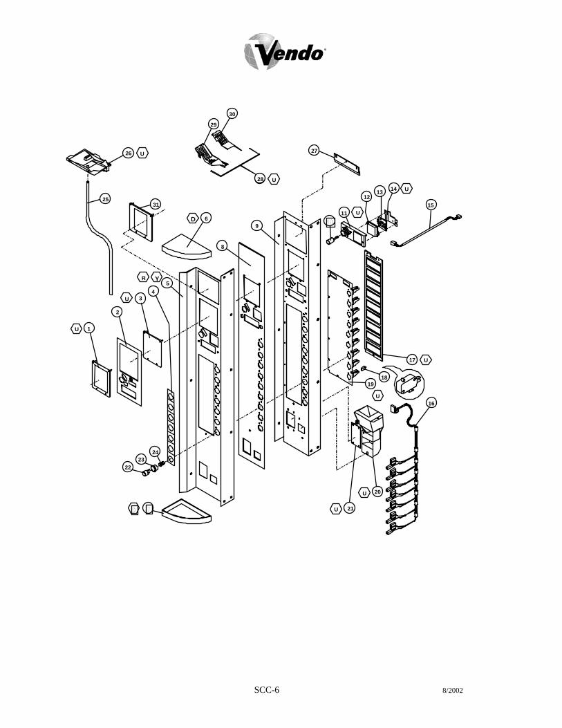
SCC-6 8/2002
30
U 26
25 31
D 6
8
29
R Y 5
4 3 U
2
1
U
24 23
22
U 21
U 20
16 U
1918
17 U
15
U 14 1312
U11
27
9
28 U

SCC-7 8/2002
MINI V-MAX COCA-COLA SELECTION PANEL
ITEM MODEL NUMBER 576 NO. DESCRIPTION QTY REQ PART NO.
~ SELECTION PANEL ASSY. 1 1112643-04 1 DBV COLLAR 1 2001201 2 COIN INSERT - DECAL 1 1044885 3 PLUG - DBV 1 2001228 4 DECORATIVE PANEL - 7-SELECT 1 1029576-7 5 OVERLAY PANEL - 7-SELECT 1 2010107 6 PANEL CAP - TOP 1 388139 7 PANEL CAP - BOTTOM 1 388140 8 COVER PANEL 1 1122419 9 SELECTION PANEL 1 2001716
10 BUTTON - COIN RETURN 1 1050473 11 GUIDE PLATE - COIN INSERT/RETURN 1 1050481 12 LENS - DISPLAY 1 1039652 13 PCB - DIGITAL DISPLAY - ELECTRONIC 1 1089678 14 DISPLAY HARNESS 1 1111252 15 SELECTION HARNESS - 7-SELECT 1 1117864 16 CARRIER STRIP ASSEMBLY 1 1017845 17 SWITCH SELECTION 7 368299 18 SWITCH MOUNT 1 1120827 19 COIN RETURN CUP ASSEMBLY 1 1079546 20 CROWN PULLER PLUG 1 1044737 21 BUTTON SELECTION 7 1016741 22 BUTTON HOUSING (BUSHING) 7 1016768 23 SPRING SELECTION 7 1029959 24 DRAIN TUBING 1 1110619 25 TRAY WATER COLLECTION 1 1110562 26 RETAINER - POS LABEL 2 1110155 27 COIN CHUTE ASSEMBLY 1 1087961 28 COIN CHUTE 1 1002333 29 COVER CHUTE 1 1002341 30 BRACKET – DBV (POS) (OPTIONAL) 1 1089716 31 MDB HARNESS (NOT SHOWN) 1 1089341 32 POS BACKING PLATE (NOT SHOWN) 1 1122389

SCC-8 8/2002

MINI V-MAX COCA-COLA LOCK ASSEMBLY
ITEM NO.
DESCRIPTION QTY REQ
PART NO.
1 T-HANDLE LOCK ASSEMBLY 1 1002635 2 T-HANDLE 1 1002392 3 PIN - STUD 1 387601 4 LOCK STUD - QUICKER LOCK 1 1049724 5 SPRING 1 1111554 6 E-RING RETAINER 3 388589 7 HEX WASHER 1 387600 8 SPRING - HEAVY 1 389690 9 FLAT WASHER 1 387718 10 FLANGE 1 1002384 11 LOCK STUD COVER 1 1122126 12 WASHER 1/2” 2 V801023 13 VAPOR SEAL 1 388132 14 BUSHING (BEARING MECH) 2 385603-4 15 LEVER - COIN RETURN 1 1052619 16 CRANK - COIN RETURN LEVER 1 1002244 17 PIVOT BRACKET - COIN RETURN 1 1002252 18 SPRING - COIN RETURN LEVER 1 1060023
SCC-9

NOTES
SCC-10
RDC-1 8/2002
ROBO - DOOR COCA-COLA

8/2002 RDC-2
16
15 ANS
135
46 U
3D12
714
8Y
R
Y
R9
10
11AE
1
5
4
2

V-MAX COCA-COLA ROBO DOOR ITEM MODEL NUMBER 720 840 NO. DESCRIPTION QTY REQ PART NO. PART NO. 1* OUTER DOOR - 9 SELECT 1 1112619-13 1112627-11 2 SIGN FACE DECAL 1 ** ** 3 EYELET TRIM 1 387125 387125 4 BUSHING 2 388094 388094 5 FLAT WASHER 3/8” (AD) 3 V801491 V801491 6 COIN CUP ASSEMBLY 1 1079546 1079546 7 LOCK COVER ASSEMBLY 1 2006724 2006724 8 DBV BEZEL 1 2006626 2006626 9 DOOR GUARD 1 1122152 1122153 10 DOOR WELD 1 1121230 1121231 11 RAIN GUARD 1 2000848 2000848 12 LEXAN PANEL 1 1086902-1 1086902-1 13 HOPPER GUARD 1 1075708 1075708 14 DBV PLUG 1 1037552 1037552 15 ROLLER 1 1120388 1120388 16 ROLLER BRACKET 1 1120552 1120522 17 DBV GASKET (NOT SHOWN) 1 1086759 1086759
FOR T-HANDLE ASSEMBLY, PLEASE SEE PAGE CC-8 & CC-9. *NOTE: WHEN ORDERING DOOR ASSEMBLY. PLEASE PROVIDE 9-CODE OR 11-CODE
AND MANUFACTURER’S DATE CODE. **NOTE: WHEN ORDERING SIGN FACE DECAL, PLEASE PROVIDE STYLE.
8/2002 RDC-3

8/2002 RDC-4

V-MAX COCA-COLA ROBO DOOR ITEM MODEL NUMBER 720/840 NO. DESCRIPTION QTY
REQ PART NO.
1 DOOR WELD - 72” 1 1121230 ~ DOOR WELD - 79” 1 1121231 2 HINGE MALE - INNER DOOR 2 1121287 3 MOUNTING BRACKET - CONTROLLER 1 1077716 4 STAND OFF 7 1121740 5 PCBA VEC 9.2 CONTROLLER 1 1110538-38 6 COVER PANEL 1 1077724 7 COIN DOOR ASSEMBLY 1 1081112 8 LATCH - COINAGE DOOR 1 1085546 9 BARRIER PANEL 1 1117147 10 BULKHEAD COIN BOX SUPPORT 1 1112155 11 DELIVERY HOPPER ASSEMBLY 1 133574 12 HARNESS CLIP 5 384692-2 13 DOOR BUMPER 2 1036912 14 RAMP/CATCH - INNER DOOR 1 1121714 15 COIN BOX 1 133563 16 LAMP HOLDER – FIXED - OPTIONAL 1 388531 17 LAMP - 20” - OPTIONAL 1 332974 18 LAMP HOLDER – PLUNGER - OPTIONAL 1 388532 19 BRACKET - LAMP HOLDER - OPTIONAL 2 1086929 20 RAIN GUTTER 1 1122404 21 DOOR HARNESS 1 1077686 22 BALLAST 1 321345-3 23 STARTER 1 321350 24 SOCKET - STARTER 1 327675-2 25 HASP - GUIDE 2 1019104 26 REINFORCEMENT HASP PLATE 1 1019147 27 HASP WELD ASSEMBLY 1 2006676 28 HASP BRACKET 1 2010136 29 MDB HARNESS (NOT SHOWN) 1 1089341
8/2002 RDC-5

76
17 U
5
10
9
84
32
1
11
12
1615
14
U13
20 21 U
22
1819
23
24
8/2002 RDC-6

V-MAX COCA-COLA ROBO DOOR SELECTION PANEL ITEM NO.
DESCRIPTION QTY REQ
PART NO.
1 BUTTON ASSEMBLY 9 1036203 2 SELECTION BUTTON - GRAY 1 1116775 3 SPRING SELECTION 1 388858 4 BUTTON HOUSING 1 1006932 5 SELECTION SWITCH 1 368299 6 SOLDOUT PLUG 1 1006975 7 SELECTION WINDOW ASSEMBLY 1 133431 8 SELECTION WINDOW 1 388223 9 SELECTION WINDOW - BACK 1 388116 10 SELECTION PANEL - 9-SELECT 1 2010092 11 SELECTION HARNESS - 9-SELECT 1 1111279 12 DISPLAY HARNESS 1 1111252 13 BUTTON - COIN RETURN 1 1050473 14 GUIDE PLATE - COIN INSERT/RETURN 1 1050481 15 LENS - DISPLAY 1 1039652 16 PCB DIGITAL DISPLAY - ELECTRONIC 1 1089678 17 COIN CHUTE ASSEMBLY 1 1087961 18 COIN CHUTE 1 1002333 19 COIN CHUTE COVER 1 1002341 20 COIN INSERT DECAL (OPTIONAL) 1 1044907-5 21 COVER PLATE - COIN INSERT - PLAIN 1 2001503 22 SECURITY PLATE - COIN INSERT 1 2001732 23 WATER COLLECTION TRAY 1 1110562 24 DRAIN TUBE 1 1110619
8/2002 RDC-7

NOTES
8/2002 RDC-8

M-1 3/2002
MAINTENANCE SECTION

M-2 3/2002
MAINTENANCE
The following section is a basic guide for general maintenance and servicing of the vendor. This section is divided into three parts: (I) Preventative Maintenance, (II) Lubrication Guide, and (III) Care and Cleaning.
I. PREVENTATIVE MAINTENANCE SUGGESTIONS: Whenever a vendor is visited on its site, the following service should be performed.
Preventative maintenance will help prevent future problems with the vendor. A. Observe the vendor and its surrounding area for any unusual indications of
problems (rear of cabinet, obstructions of the air flow, dark spots on the sign face, etc.).
B. Open the door and visually check the inside of the vendor (water accumulation, rust marks, moisture around the edges of the inner door, etc.).
C. Check the fluorescent lamps, replace as necessary. Replace all lamps within 24 to 48 hours of burnout. This will prevent damage to the ballast.
D. Check the product temperature for proper cooling. E. Check evaporator drain for obstruction; water in the evaporator area must
drain to the condensation pan. F. Empty condensation pan. G. Clean the condenser, free vanes of dirt, lint, etc. H. Check that evaporator fan(s) run normally. I. Check that the compressor and condenser fan run normally. J. Investigate any unusual sounds (fan blades hitting something, refrigeration
lines rattling, etc.). K. Clean coin acceptor. L. Deposit all coinage accepted by the vendor to check for proper operation of
the coinage mechanism. M. Test the vendor and make a report on the problems.
II. LUBRICATION GUIDE: Lubricate indicated areas as directed on the chart below.
INTERVALS PARTS LUBRICANT Every six months Top door hinge, hinge pin at the
base of cabinet, door latch cam to cabinet strike, T-handle shaft & latch.
Grade two, high low temperature grease
As necessary Pivot area of bucket and gate Grade two, high low temperature grease

M-3 3/2002
III. CARE AND CLEANING
DO NOT USE WATER JET FOR CLEANING.
AVOID USING WATER OR ANY OTHER LIQUIDS NEAR ELECTRONIC COMPONENTS
A. GENERAL PROCEDURE (painted metal areas) Wash vendor with soap and water. The exterior may be waxed with any good
automobile wax. B. FRESH PAINT SPLASHES, GREASE, GLAZING COMPOUND REMOVAL Before drying, these elements may be removed by rubbing lightly with grade “A”
Naptha (or equivalent grade solvent). After removal, use general cleaning procedure (listed above in A).
C. LABELS AND STICKER REMOVAL Use Kerosene, VM&P grade Naptha or petroleum spirits for removal. When the label
material does not allow penetration of solvent (such as vinyl), the application of heat (hair blow dryer) will soften the adhesive and promote removal. CAUTION: Excessive heat can cause surface damage. After the label is removed, use the general cleaning procedure (listed above in A).
D. SCRATCH REMOVAL Remove or minimize hairline scratches and minor abrasions by using any good
quality automobile polish. Test product before using. E. LEXAN SIGNS To clean Lexan sign faces the following procedure is recommended. 1. Wash sign with mild soap or detergent and lukewarm water. 2. Using a soft cloth or sponge, gently wash the sign. DO NOT SCRUB! 3. Rinse well with clean lukewarm water. 4. Dry thoroughly with a chamois or cellulose sponge (to prevent water
spotting). DO NOT USE SQUEEGEE! NOTE: Most organic solvents, petroleum, spirits, or alcohol are NOT compatible
cleaning materials for Lexan signs. Usage of those materials could permanently damage the sign.
F. REFRIGERATION AREA
The condenser and evaporator must be kept clean for efficient operation. Be sure all vanes and tubing are clean and clear of obstruction; this allows free passage of air. Clean with a brush, a vacuum cleaner or compressed air. Keep cabinet drain open; clean as necessary.

M-4 3/2002
REFRIGERATION OPERATION
The refrigeration operation section is divided into three areas: Basic Refrigeration Principle, Detailed Vending Machine Refrigeration Cycle, and Parts Description.
BASIC REFRIGERATION PRINCIPLE What a refrigeration system really accomplishes is the transfer of heat. A refrigeration system removes the excess heat from a refrigerated area and then transfers it to a condenser where it is dissipated. As heat is removed, the refrigerated area cools. In vending machines, large quantities of the heat must be transferred rapidly, economically and efficiently. This process must be able to withstand continuous repetition, without loss of refrigerant, over an extended period. The most common system used in the vending industry is the vapor compression (or simple compression) cycle system. It consists of four basic elements: An evaporator, a compressor, a condenser, and a pressure-reducing device (all part of a sealed system). The compression system operates at two pressure levels: The low evaporating pressure and the high condensing pressure. The refrigerant acts as the transport medium, in which heat is moved from the evaporator to the condenser; at the condenser, the heat is dissipated into the surrounding air. The liquid refrigerant changes from a liquid to a vapor and back to a liquid again. This change of state allows the refrigerant to absorb, and rapidly discharge, large quantities of heat efficiently. BASIC VAPOR COMPRESSION SYSTEM CYCLE: In the evaporator the liquid refrigerant vaporizes. This change occurs at a temperature low enough to absorb heat from the refrigerated space. The temperature of vaporization is controlled by the pressure maintained in the evaporator (the higher the pressure, the higher the vaporization point). The compressor pumps the vapor from the evaporator, through the suction line, and to the condenser. The compressor takes the low pressure vapor and compresses it, increasing both the pressure and the temperature. The compressor pumps the vapor at a rate rapid enough to maintain the ideal pressure. The hot high pressure vapor is forced out of the compressor, into the discharge line and then into the condenser. Air is blown through the condenser, allowing heat to transfer from the condenser and into the passing air. As the heat is removed, the stored refrigerant is condensed into a liquid. The liquid refrigerant is stored in the lower tube of the condenser. This is where it flows through the capillary tube back into the evaporator, where the refrigeration cycle is repeated.
M-5 3/2002
DETAILED REFRIGERATION CYCLE
The following is a detailed refrigeration cycle as it applies to the refrigeration system installed in Vendo equipment. (Refer to the flow chart in Figure 1.) As the air temperature in the cabinet rises, the electronic temperature sensor reports the air temperature to the electronic controller. The electronic controller actuates the refrigeration control relay which turns on both the compressor and condenser fan motor. The evaporator fan pulls air from the front of the refrigerated space of the cabinet. It pulls the air through the evaporator, and blows it up the back of the vend stack. (The evaporator fan runs continuously.) As the air passes through the evaporator, heat is drawn from the air and transferred to the liquid refrigerant. As the cooled air circulates through the vend stack, heat is drawn from the product and transferred to the circulating air. The heated air is again drawn through the evaporator where the heat is removed. In the evaporator, the liquid refrigerant draws heat from the circulating air. As refrigerant receives heat, it vaporizes. The compressor pumps the vapor from the evaporator and compresses it, increasing both pressure and temperature. The compressor forces the compressed vapor out, through the discharge line and into the condenser. The condenser fan pulls air through the condenser. As the hot refrigerant vapor passes through the condenser tubes, heat is drawn from the vapor. This heat is dissipated into the passing air. The air then exits out the back of the vendor. As the refrigerant vapor in the condenser lines is cooled, it returns to a liquid state. From the condenser the liquid flows to the drier. The drier removes any water and solid particles from the liquid refrigerant. The cooled liquid refrigerant continues from the drier, through the capillary tube, to the evaporator. The capillary tube steadies the flow rate of the refrigerant. Its small inside diameter allows the pressure in the evaporator to remain low while the pressure in the condenser is high. The cool refrigerant in the evaporator draws heat from the circulating air in the cabinet. As the temperature in the cabinet drops, the electronic temperature sensor reports the air temperature to the electronic controller. The electronic controller deactivates the refrigeration control relay which turns off the compressor and condenser fan motor. When the air temperature in the cabinet rises above the electronic controller’s cut in setting, the compressor and the condenser fan engage again.

FIGURE 1
DISCHARGE
SIDE
VAPOR
HIGH PRESSURE
COMPRESSORSUCTION
50
110
VAPOR
CONDENSER
FAN
LIQUID
DRIERLIQUID
CONDENSER
ACCUMULATOR
EVAPORATOR
EVAPORATOR
FAN
LOW PRESSURE
CAPILLARY RESTRICTION TUBE
FRONT
M-6 3/2002
REFRIGERATION PARTS DESCRIPTION
The compressor, condenser, drier, capillary tube, evaporator, and accumulator are part of a sealed system (refer to Figure 2). These items are not available separately. COMPRESSOR The compressor takes in low pressure vapor and compresses it, increasing both the pressure and the temperature. The hot high pressure gas is forced out to the condenser. The compressor and the motor that drives the compressor are sealed inside a housing. The compressor, as a unit, is mounted on the refrigeration base. The base is mounted in the bottom of the vendor, outside the sealed refrigeration space. CONDENSER The condenser takes heat out of the high pressure vapor that it receives from the compressor. As the vapor passes through the condenser it cools and returns to a liquid state. The condenser is mounted to the refrigeration base near the front of the vendor. It is easily accessible for cleaning. DRIER The drier is a molecular sieve strainer drier. It removes water and solid particles from refrigerant liquid. One side of the drier is connected to the outlet line of the condenser; the other side is connected to the capillary tube going to the evaporator.
CAPILLARY TUBE The capillary tube controls, at a steady rate, the flow of refrigerant liquid to the evaporator. It has a very small inside diameter to keep pressure in the evaporator low while the pressure in the condenser is high. It is the connecting link between the condenser and evaporator. EVAPORATOR The evaporator is a heat transference device. It removes the heat from the air in a refrigerated space and transfers it to the refrigerant liquid. This liquid evaporates into a vapor and is removed by the compressor. The evaporator is mounted inside the refrigerated space of the cabinet, directly below the delivery chute. ACCUMULATOR The accumulator traps any refrigerant liquid, which did not boil off into a vapor before reaching the compressor. The accumulator allows the refrigerant liquid to boil off as a vapor (preventing damage to the compressor). It also prevents suction line sweating. The accumulator is mounted in the suction line on the outline side of the evaporator.
M-7 3/2002

CONDENSER FAN ASSEMBLY
AND CAPACITOR
CONDENSER
EVAPORATOR
EVAPORATOR FANASSEMBLY
REFRIGERATION
SENSOR
CONTROLRELAY
TEMPERATURE
COMPRESSOR
STARTING RELAY
CAPILLARY TUBE
ACCUMULATOR
FIGURE 2
M-8 3/2002

The parts listed below are not part of the sealed refrigeration system and are available separately.
START CAPACITOR - P/N: 1112805 The start capacitor is used to increase power during the start. This additional power will help get the compressor running in case there is any back pressure. STARTING RELAY – INCLUDED IN ASSEMBLY P/N 513506066 The starting relay is mounted in the terminal box on the outside of the compressor under the housing. When the compressor first starts up, the starting relay closes and completes a starting circuit. When the compressor motor reaches operating speed, the starting relay opens and breaks the starting circuit. THERMAL OVERLOAD SWITCH – INCLUDED IN ASSEMBLY P/N 513506066 The thermal overload switch is mounted in the terminal box on the outside of the compressor under the housing. If the compressor motor gets hot or draws too much current, the thermal overload opens and breaks the starting and running circuit of the motor. As the motor cools, the thermal overload closes, allowing the compressor to resist. REFRIGERATION CONTROL RELAY - P/N: 1079724 The refrigeration control relay is mounted behind the left side air dam. This relay controls the compressor and condenser fan motor via the electronic control board. TEMPERATURE SENSOR - P/N: 1079716 The temperature sensor is mounted in the inlet airflow of the evaporator. This sensor monitors the air temperature and reports it to the electronic controller so that the controller can operate the refrigeration system via the refrigeration control relay.
M-9 3/2002

NOTES
M-10 3/2002

T-1 4/2002
TROUBLESHOOTING

T-2 4/2002
VENDO WARRANTY For V-Max Equipment Purchased prior to 10/1/01
NEW EQUIPMENT I. This is a Limited Warranty. II. The Vendo Company warrants, to the original purchaser, each part of each new vending machine for a period
of fifteen (15) months from the date of shipment, to be free from defects in material and workmanship. This Warranty DOES NOT include light bulbs, fluorescent tubes, fuses, finish, or operating supplies.
III In addition to the fifteen (15) month Warranty on each part of each new vending machine, the hermetically-
sealed refrigeration system used in machines designed to vend bottles, cans, and aseptic cartons is warranted to be free from defects in materials and workmanship for an additional four (4) years, provided the hermetically-sealed portion of the system has not been opened or damaged. Hermetically-sealed refrigeration systems DO NOT include fan motors, temperature controls, capacitors, overload switches or starting relays which are covered by the fifteen (15) month Warranty.
IV. Electronic control boards and the LED display are warranted against defects in material and workmanship for
an additional two (2) years. The Company, at its option, will either repair or replace products that prove to be defective.
V. To qualify for Warranty replacement, all requests for returns must be made in writing within the warranty period,
accompanied by a record of the cabinet model and serial number. If a return is found to be inoperative due to defects in material and/or workmanship, we will, at our option, make necessary repairs or furnish a reconditioned or new replacement part or refrigeration system at no charge.
VI. The Vendo Company will pay normal transportation charges on parts and refrigeration system replaced under
this Warranty. If special handling or premium transportation is requested, these charges are assumed by the purchaser.
VII. Any parts and/or refrigeration systems replaced during the warranty period are warranted for the remaining
time on the original warranty. VIII. This Warranty DOES NOT apply to machines located outside the United States and Canada, reconditioned
equipment, equipment sold “as is”, or components designed to work on electric currents other than 110v/120v 60hz cycle or 208v/220v 50hz cycle, as specified on the serial tag.
IX. Title and risk of loss pass to the purchaser on delivery of the vending machine, replacement parts and/or
refrigeration system to the common carrier. All loss and damage claims are the responsibility of the purchaser and must be filed with the delivering carrier.
X. This Warranty DOES NOT include any service guarantee, either explicit or implied, nor will it extend to cover
incidental or consequential damages or damages resulting from purchaser or third party negligence, accident, vandalism, or an act of God.
XI. The Vendo Company reserves the right to make design changes, additions to, and improvements upon any of
our product without incurring any obligation to incorporate same on any product previously manufactured. XII. This Warranty is in lieu of all other express warranties or other obligations or liabilities on our part, and we
neither assume nor authorize any person to assume for us, any other obligation for liability in connection with the sale of said machines or parts thereof. EXCEPT AS SPECIFICALLY PROVIDED HEREIN, THERE ARE NO WARRANTIES GIVEN, EITHER EXPRESS OR IMPLIED, AND ALL OTHER WARRANTIES, INCLUDING SPECIFICALLY BUT WITHOUT LIMITATION WARRANTIES OF MERCHANTABILITY AND FITNESS FOR PARTICULAR PURPOSE, ARE HEREBY EXPRESSLY DISCLAIMED.
THE VENDO COMPANY 2/1996

T-3 4/2002
THE VENDO COMPANY NEW EQUIPMENT WARRANTY V-MAX VENDING MACHINES
United States / Canada
I. This warranty benefits only the original purchaser of a new vending machine, and does not benefit any transferee of a new vending machine from the original purchaser.
II. The Vendo Company warrants each part of each new vending machine for a period of fifteen (15) months from the date of shipment,
to be free from defects in material and workmanship. This Warranty DOES NOT include light bulbs, fluorescent tubes, fuses, finish or operating supplies.
III. The hermetically-sealed refrigeration system used in machines designed to vend bottles, cans, and aseptic cartons is warranted to
be free from defects in materials and workmanship for six (6) years, provided the hermetically-sealed portion of the system has not been opened or damaged. This six (6) year warranty DOES NOT include fan motors, temperature controls, capacitors, overload switches or starting relays.
IV. Electronic control boards, LED displays and Vend motors, are warranted against defects in material and workmanship for five (5)
years.
V. Return authorization is required to qualify for warranty replacement. All requests for returns must be in writing or via phone, within the warranty period, and accompanied by a record of the cabinet model and serial number of the machine. Freight carrier return tickets will only be issued to the machine owner for refrigeration system returns. This warranty is voided when the serial number of a machine is missing. If a return is found to be inoperative due to defects in material and/or workmanship, we will, at our option, make necessary repairs or furnish a reconditioned or new replacement part or refrigeration system at no charge.
VI. “Return Material Tags” indicating cabinet model, machine serial number and explanation of defect must accompany all returned
parts or machines. “Return Material Tags” will be furnished upon request. On-site inspection of defective parts, at The Vendo Company’s option, may be used to facilitate credit approval or the replacement of parts.
VII. The Vendo Company will pay normal transportation charges on refrigeration systems and parts replaced under this warranty. If
special handling or premium transportation is requested, those charges will be assumed by the original purchaser.
VIII. Any parts and/or refrigeration systems replaced during the warranty period are warranted for the remaining time on the original warranty.
IX. This warranty DOES NOT apply to machines located outside the United States and Canada, reconditioned equipment, equipment
sold “as is”, or components designed to work on electric currents other than 110v/120hz 60 cycle, as specified on the serial tag.
X. Title and risk of loss pass to the original purchaser on delivery of the vending machine, replacement parts and/or refrigeration system to the common carrier. All loss and damage claims are the responsibility of the original purchaser and must be filed with the delivering carrier.
XI. This warranty DOES NOT include any service guarantee, either explicit or implied, nor will it extend to cover incidental or
consequential damages resulting from the original purchaser or third party negligence, accident, vandalism, or an act of God.
XII. The Vendo Company reserves the right to make design changes, additions to, and improvements upon any of our product without incurring any obligation to incorporate same on any product previously manufactured.
XIII. This warranty is in lieu of all other express warranties or other obligations or liabilities on our part, and we neither assume nor
authorize any person to assume for us, any other obligation for liability in connection with the sale of said machines or parts thereof. EXCEPT AS SPECIFICALLY PROVIDED HEREIN, THERE ARE NO WARRANTIES GIVEN, EITHER EXPRESS OR IMPLIED, AND ALL OTHER WARRANTIES, INCLUDING SPECIFICALLY BUT WITHOUT LIMITATION WARRANTIES OF MERCHANTABILITY AND FITNESS FOR PARTICULAR PURPOSE, ARE HEREBY EXPRESSLY DISCLAIMED.

T-4
PARTS RETURN PROCEDURES
1. All parts returned must be accompanied by a material return tags (P/N 1122825) Tag must clearly state the reason for the return and the Return Goods Authorization Number received from your Vendo Customer Service Rep at 1-800-344-7216. (Return tags are available from our parts department upon request).
2. All parts should be properly wrapped and packed securely to avoid further damage.
3. To replace an inoperative part, please use the following instructions
4. Complete the return tag making sure to fill in ALL requested information to ensure prompt processing. Keep top (white) copy for your records. Attach tag to inoperative part and send it by the most inexpensive method of transportation (Federal Express Ground or Overnight Transportation) To: THE VENDO COMPANY, 4015 EAST RAINES ROAD, MEMPHIS, TENNESSEE 38118.
5. Be sure to check ( ) the box marked “credit” and to fill in the invoice number covering the part sent to you or check the box marked “replace with like part”.
6. If the box is marked for replace with like part, a like part will be shipped at no charge if our inspection shows that the inoperative part became defective during the warranty period.
7. If the box is marked for credit, a credit will be issued to cancel the invoice on which the replacement part was shipped. This credit will include any applicable prepaid transportation charges. To receive credit the inoperative part must be returned within 30 days from the date the replacement was shipped.
8. Vendo does not issue cash credit for the return of any part or accessory.
REFRIGERATION UNIT RETURN PROCEDURE
1. All refrigeration units returned must be accompanied by a material return tag (P/N 1122826). Tag must clearly state the reason for the return and the Return Goods Authorization Number received from your Vendo Customer Service Rep at 1-800-344-7216. (Return tags are available from our parts department upon request).
2. All refrigeration units should be properly wrapped and packed securely to avoid further damage.
3. To replace an inoperative part, please use the following instructions. 4. Complete the return tag making sure to fill in ALL requested information to ensure prompt processing. Keep top (white)
copy for your records. Attach tag to inoperative part and send it by the most inexpensive method of transportation (Federal Express Ground or Overnight Transportation) To: THE VENDO COMPANY 7209 N. INGRAM AVE. FRESNO, CA. 93650
5. Be sure to check ( ) the box marked “credit” and to fill in the invoice number covering the part sent to you or check the
box marked “replace with like part”.
6. If the box is marked for replace with like part, a like part will be shipped at no charge if our inspection shows that the inoperative part became defective during the warranty period.
7. If the box is marked for credit, a credit will be issued to cancel the invoice on which the replacement part was shipped.
This credit will include any applicable prepaid transportation charges. To receive credit the inoperative part must be returned within 30 days from the date the replacement was shipped.
8. Vendo does not issue cash credit for the return of any refrigeration unit.
*Canadian and International customers please contact your Customer Service Representative for return instructions
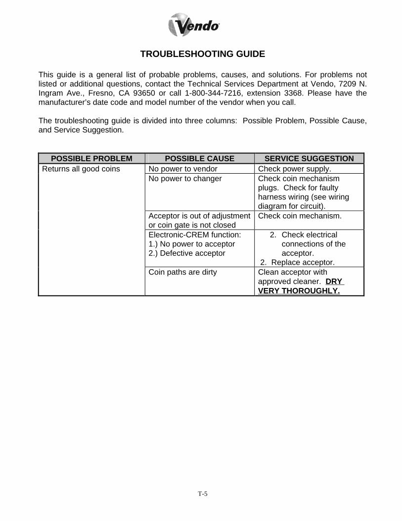
T-5
TROUBLESHOOTING GUIDE
This guide is a general list of probable problems, causes, and solutions. For problems not listed or additional questions, contact the Technical Services Department at Vendo, 7209 N. Ingram Ave., Fresno, CA 93650 or call 1-800-344-7216, extension 3368. Please have the manufacturer’s date code and model number of the vendor when you call. The troubleshooting guide is divided into three columns: Possible Problem, Possible Cause, and Service Suggestion.
POSSIBLE PROBLEM POSSIBLE CAUSE SERVICE SUGGESTION Returns all good coins No power to vendor Check power supply. No power to changer Check coin mechanism
plugs. Check for faulty harness wiring (see wiring diagram for circuit).
Acceptor is out of adjustment or coin gate is not closed
Check coin mechanism.
Electronic-CREM function: 1.) No power to acceptor 2.) Defective acceptor
2. Check electrical connections of the acceptor.
2. Replace acceptor. Coin paths are dirty Clean acceptor with
approved cleaner. DRY VERY THOROUGHLY.

T-6
POSSIBLE PROBLEM POSSIBLE CAUSE SERVICE SUGGESTION
Money accepted, no product vended
Bad selection switch(es) Check selection switches, replace as necessary.
Bad selection switch harness connection
Check harness connection.
Sold-out switch (of column selected) inoperative
Check switch, replace as necessary.
Vend motor runs until two or three products are vended or vend motors run continuously
Improper cam lobe adjustment
Check cam for proper arrangement of cam lobes (see product set-up guide).
Motor position switch not making proper contact with cam lobe
Check lever for proper lever positioning and freedom of movement.
Refrigeration unit will not run at all
No power to vendor Check power supply, also check service cord connections.
Bad temperature sensor Check / replace. Bad refrigeration relay Check / replace.
Compressor will not start Overload Protector
inoperative Check overload (apply insulated jumper across terminal, if compressor starts, replace overload).

T-7
POSSIBLE PROBLEM POSSIBLE CAUSE SERVICE SUGGESTION
Compressor will not start, condenser fan motor running - unit hot (power to compressor)
Starting relay or capacitor inoperative
Check relay or capacitor, replace.
Compressor inoperative Disconnect power to vendor, remove all leads from compressor, check continuity from “common”, “start” and “run” to compressor case. If continuity shows, replace compressor. Also check from “common to start” (using continuity or IHMS). If meter fails to show reading replace compressor.
Compressor starts but does not run
Will not cycle Check overload and contact, replace overload if necessary.
Starting relay stays closed Replace relay. Compressor motor problem Check, replace. Compressor runs but cabinet temperature warm
Loss of refrigerant Replace refrigeration unit. (Note: Any work of this nature done without express permission from The Vendo Company can void refrigeration unit warranty.)
Condenser fan not working Check circuit to run motor. Replace motor. Check for obstruction of fan blade.
Blocked or dirty condenser (Refer to initial installation in the service manual)
Check condenser vanes for obstruction, lint or dirt. Clean, also check for proper air flow through refrigeration area.
Evaporator fan not working Check circuit to fan motor. Replace motor, also check for obstruction of fan blade.
Bad inner door seal Check for moisture on seal. Adjust inner door as necessary (See initial set-up of service manual). Replace door seal.

T-8
POSSIBLE PROBLEM POSSIBLE CAUSE SERVICE SUGGESTION
Evaporator frosted over Water at base of evaporator unit
Check for proper drainage (such as plugged drain, kinks in drain tube, etc.), check door seal.
Product freezing up too cold Temperature setting too low Adjust temperature setting in electronic controller.
Excessive noise Fan blade bent or hitting shroud
Straighten, relocate shroud position, or remove shroud.
Fan motor noisy Replace if necessary. Refrigeration base loose or
bent Tighten bolt or replace if necessary.
Both compressor and condenser fan motors will not operate
Bad refrigeration control relay
Test relay using relay test function of the electronic controller. Replace relay if necessary.
Bad wiring connection at refrigeration control relay
Check wiring connections. Make corrections if necessary.

T-9
NOTES

LMV-1
COCA - COLA
LEAN MARKETING VENDOR PARTS SECTION
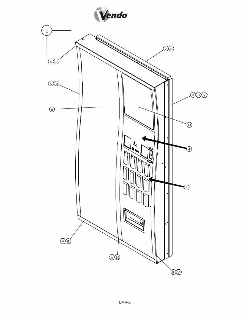
LMV-2
2
4
3
5
9
6
7
8
10
11
V
V
V
V
S
AE
Y
1
9 V

LMV-3
LEAN MARKETING VENDOR COCA-COLA DOOR MODEL NUMBERITEM
NO. DESCRIPTION QTY REQ
840 PART NO.
720 PART NO.
576 PART NO.
1 DOOR ASSEMBLY 1 * * * 2 RAIN GUARD 1 2000848 2000848 2001031 3 DOOR GUARD 1 2010177-2 2010177-3 2010177-3 4 TRANSACTION ASSEMBLY (SEE LMV8-
9) 1 ~ ~ ~
5 SELECTION ASSEMBLY (SEE LMV6-7) 1 ~ ~ ~ 6 SIGN FACE 1 ** ** ** 7 TOP TRIM 1 1124342-1 1124342-1 1124339-1 8 BOTTOM TRIM 1 1124340-1 1124340-1 1124341-1 9 SIDE TRIM 2 1124344-1 1124343-1 1124343-1 10 CENTER TRIM 1 1124346-1 1124345-1 1124345-1 11 AD PANEL 1 ** ** **
*NOTE: WHEN ORDERING PLEASE PROVIDE 9-CODE OR 11-CODE. **NOTE: WHEN ORDERING SIGN FACE AND AD PANEL, PLEASE PROVIDE STYLE.

LMV-4
27
AN
26
28
24
25
23
17
16
13 12
22
2
3
8
7
9
5
6
20
21
1
15
14
10
H
H J
F
AE U J H
G D
F
F
I
11
29
30
32
18
19
4
31
33

LMV-5
LEAN MARKETING VENDOR COCA-COLA DOOR
MODEL NUMBERITEM NO. DESCRIPTION QTY
REQ
840 PART NO.
720 PART NO.
576 PART NO.
1 DOOR WELD 1124338 1124337 1124336 2 OVERLAY PANEL (SEE PAGE LMV7) 1 ~ ~ ~ 3 EYELET, HOPPER TRIM 1 1124350 1124350 1124350 4 DOOR BUMPER 1 1036912 1036912 1036912 5 DBV VAULT PANEL 1 1124711 1124711 1124711 6 DBV VAULT PANEL, LOCKSIDE 1 1123907 1123907 1123907 7 LAMP, T8, 48” 2 1121173-2 1121173-2 1121173-2 8 LAMP BRACKET 1 1124194 1124233 1124194 9 LAMP HARNESS 1 1124307 1124307 1124307 10 BALLAST 1 1122758 1122758 1122758 11 COINAGE DOOR 1 1124229 1124229 1124229 12 COINAGE CHUTE 1 1123851 1123851 1123851 13 COINAGE COIN RETURN CHUTE 1 1124230 1124230 1124230 14 LATCH, COINAGE DOOR 1 1085546 1085546 1085546 15 HINGE, COINAGE DOOR 2 388124 388124 388124 16 HOPPER ASSEMBLY 1 1123886 1123886 1123886 17 COIN RETURN CUP 1 1123885 1123885 1123885 18 HOPPER FLAP 1 1123739 1123739 1123739 19 RETAINER, HOPPER 1 1122875 1122875 1122875 20 COIN BOX HOUSING ASSEMBLY 1 1124693 1124693 1124693 21 COIN RETURN CHUTE 1 1123849 1123849 1123849 22 COIN BOX ASSEMBLY 1 1124391 1124391 1124391 23 INNER DOOR RAMP 1 1121714 1121714 1121714 24 ROLLER BRACKET 1 1120552 1120552 1120552 25 ROLLER 1 1120388 1120388 1120388 26 VEC MOUNTING BRACKET 1 1120544 1120544 1120544 27 CONTROL BOARD, VEC 10 1 1120574-107 1120574-107 1120574-10728 RAIN CURTAIN, CONTROLLER 1 1120718 1120718 1120718 29 RETAINER, AD PANEL 32” * 1124903 1124903 1124903 30 RETAINER, AD PANEL 39” 1 1124902 ~ ~ 31 COIN DOOR WEAR PLATE 1 1124228 1124228 1124228 32 INNER DOOR HINGE, MALE 2 1121287 1121287 1121287 33 LOCK STUD GUIDE 1 1121356 1121356 1121356 34 MDB HARNESS (NOT SHOWN) 1 1124570 1124570 1124570 35 DOOR HARNESS (NOT SHOWN) 1 1120435 1120435 1120435 36 RAIN CURTAIN, LIGHT (NOT SHOWN) 2 1121838-1 1121838-1 1121838-1 37 RAIN CURTAIN, BALLAST (NOT SHOWN) 1 1121837 1121837 1121837
* NOTE: FOR 840 MACHINE A QTY OF TWO (2) IS REQUIRED. FOR 720 & 576 A QTY OF THREE (3) IS REQUIRED.

LMV-6
4
3
6
7
5
2
43
6
7
5
8
1
2
U
YV
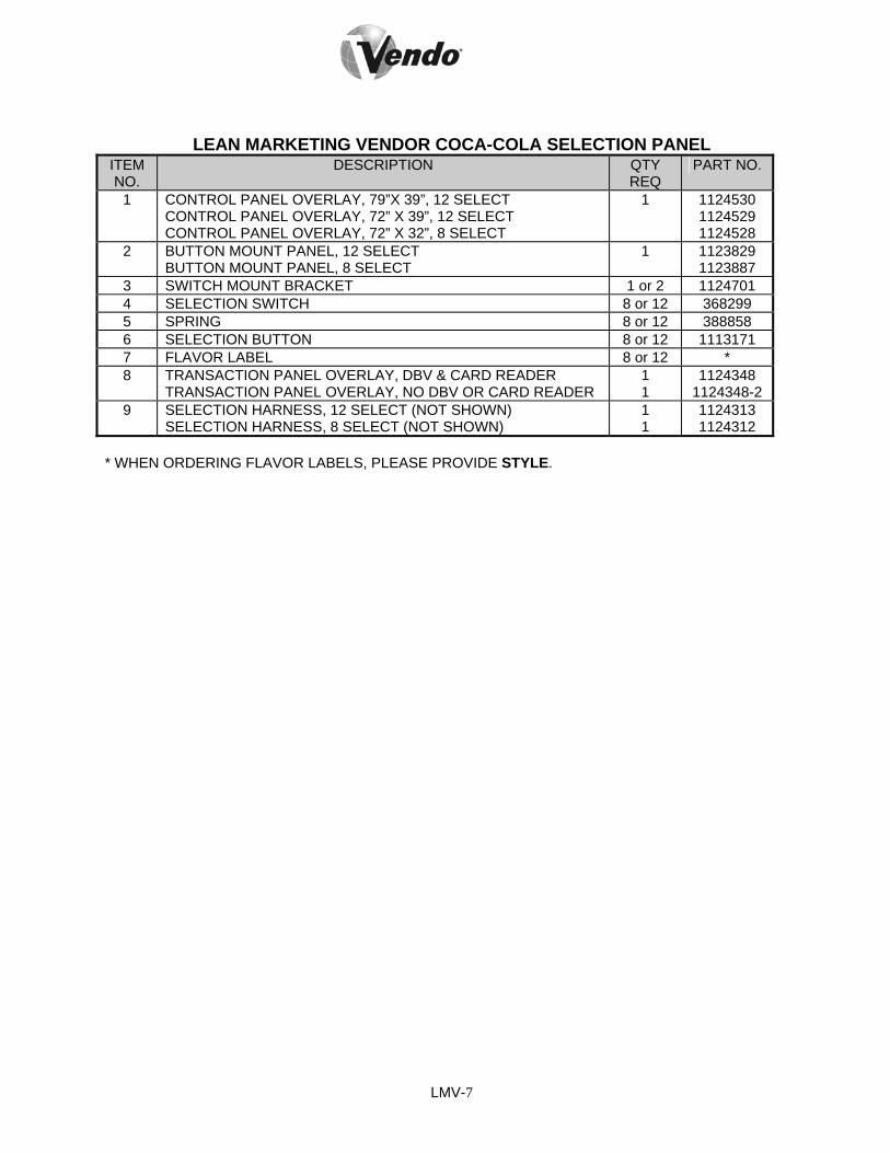
LMV-7
LEAN MARKETING VENDOR COCA-COLA SELECTION PANEL ITEM NO.
DESCRIPTION QTY REQ
PART NO.
1 CONTROL PANEL OVERLAY, 79”X 39”, 12 SELECT CONTROL PANEL OVERLAY, 72” X 39”, 12 SELECT CONTROL PANEL OVERLAY, 72” X 32”, 8 SELECT
1 1124530 1124529 1124528
2 BUTTON MOUNT PANEL, 12 SELECT BUTTON MOUNT PANEL, 8 SELECT
1 1123829 1123887
3 SWITCH MOUNT BRACKET 1 or 2 1124701 4 SELECTION SWITCH 8 or 12 368299 5 SPRING 8 or 12 388858 6 SELECTION BUTTON 8 or 12 1113171 7 FLAVOR LABEL 8 or 12 * 8 TRANSACTION PANEL OVERLAY, DBV & CARD READER
TRANSACTION PANEL OVERLAY, NO DBV OR CARD READER 1 1
1124348 1124348-2
9 SELECTION HARNESS, 12 SELECT (NOT SHOWN) SELECTION HARNESS, 8 SELECT (NOT SHOWN)
1 1
1124313 1124312
* WHEN ORDERING FLAVOR LABELS, PLEASE PROVIDE STYLE.

LMV-8
1
6 12
13
14
15
16
17
18
19
21
22
F
F
20
24
23
2526
2 3
4
7
5 6
10
8
9
11
27 28

LMV-9
LEAN MARKETING VENDOR COCA-COLA TRANSACTION ASSEMBLY ITEM NO.
DESCRIPTION QTY REQ
PART NO.
1 T-HANDLE LOCK ASSEMBLY 1 1124191 2 T-HANDLE 1 1116732 3 SPRING 1 389691 4 E-RING RETAINER 1 388589 5 HEX WASHER 1 387600 6 LOCK STUD 1 1122399 7 PIN - STUD 1 387601 8 FLANGE 1 1116724 9 SPRING - HEAVY 1 389690
10 FLAT WASHER 1 V801023 11 E-RING RETAINER 1 388589 12 LOCK COVER (OPTIONAL) 1 1120340 13 HASP - LOCK COVER (OPTIONAL) 1 1120339 14 COIN RETURN BUTTON 1 1050473 15 COIN INSERT GUIDE PLATE 1 1123820 16 DISPLAY COVER 1 1039652 17 DISPLAY 1 1089678 18 TRANSACTION PANEL 1 1124681 19 DBV PLATE 2 1124614 20 DBV GASKET 2 1086759 21 COIN INSERT CHUTE 1 1123900 22 COIN INSERT CAP 1 1123898 23 COIN RETURN LEVER ASSEMBLY 1 1124371 24 COIN RETURN CRANK 1 1123823 25 COIN RETURN LEVER MOUNT 1 1123822 26 SHOULDER WASHER, NYLON 1 1122715 27 VAPOR SEAL 1 388132 28 LOCK STUD COVER 1 1122126 29 DISPLAY HARNESS (NOT SHOWN) 1 1120438

LMV-10
5
G 4
1
2
K3
6
7
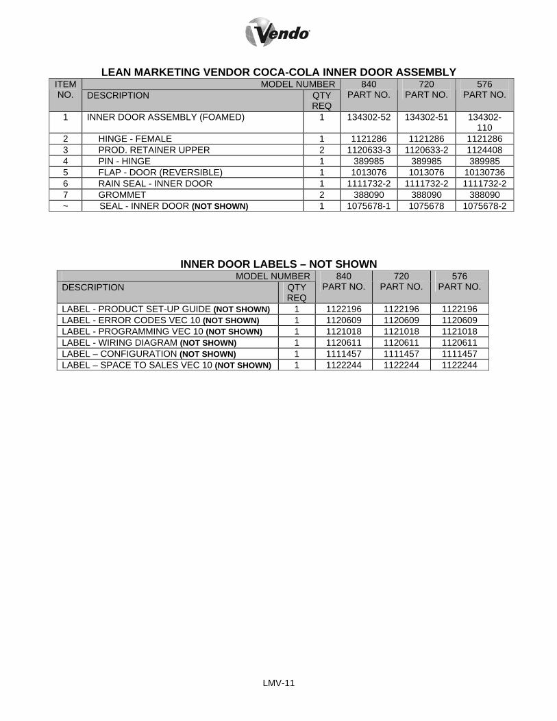
LMV-11
LEAN MARKETING VENDOR COCA-COLA INNER DOOR ASSEMBLY MODEL NUMBERITEM
NO. DESCRIPTION QTY REQ
840 PART NO.
720 PART NO.
576 PART NO.
1 INNER DOOR ASSEMBLY (FOAMED) 1 134302-52 134302-51 134302-110
2 HINGE - FEMALE 1 1121286 1121286 1121286 3 PROD. RETAINER UPPER 2 1120633-3 1120633-2 1124408 4 PIN - HINGE 1 389985 389985 389985 5 FLAP - DOOR (REVERSIBLE) 1 1013076 1013076 10130736 6 RAIN SEAL - INNER DOOR 1 1111732-2 1111732-2 1111732-2 7 GROMMET 2 388090 388090 388090 ~ SEAL - INNER DOOR (NOT SHOWN) 1 1075678-1 1075678 1075678-2
INNER DOOR LABELS – NOT SHOWN MODEL NUMBER
DESCRIPTION QTY REQ
840 PART NO.
720 PART NO.
576 PART NO.
LABEL - PRODUCT SET-UP GUIDE (NOT SHOWN) 1 1122196 1122196 1122196 LABEL - ERROR CODES VEC 10 (NOT SHOWN) 1 1120609 1120609 1120609 LABEL - PROGRAMMING VEC 10 (NOT SHOWN) 1 1121018 1121018 1121018 LABEL - WIRING DIAGRAM (NOT SHOWN) 1 1120611 1120611 1120611 LABEL – CONFIGURATION (NOT SHOWN) 1 1111457 1111457 1111457 LABEL – SPACE TO SALES VEC 10 (NOT SHOWN) 1 1122244 1122244 1122244

LMV-12
2
1 AE

LMV-13

LMV-14
LEAN MARKETING VENDOR COCA-COLA CABINET ASSEMBLY ITEM NO.
DESCRIPTION QTY REQ
PART NO.
1 PRODUCT CHUTE ASSEMBLY, 39” 1 2008643-03 ~ PRODUCT CHUTE ASSEMBLY, 32” 1 2008643-06 2 TOP HINGE ASSEMBLY 1 2000805-03

LMV-15
NOTES