ventilation manual - home - ufswufsw.org/pdfs/ventilation.pdf · project manager, ventilation...
TRANSCRIPT

VENTILATION MANUAL
SAN FRANCISCO FIRE DEPARTMENT

Blank Page

Ventilation Manual Revised January 2008
San Francisco Fire Department
698 Second Street San Francisco CA 94107
415-558-3200

Chief of Department Joanne Hayes-White
Manual Revision Project Deputy Chief Gary P. Massetani
Assistant Deputy Chief Thomas A. Siragusa Assistant Chief James A. Barden
Captain Jose Luis Velo
Project Manager, Ventilation Manual Captain James Lambrechts
Contributors Captain Bryan Rubenstein
Captain James Kircher Captain Clyde Christobal
Published by: Division of Training 2310 Folsom Street
San Francisco, CA 94110 Phone: (415) 970-2000 Revised: January 2008
This manual is sole property of the San Francisco Fire Department

FOREWORD
The goal of this manual is to establish standard operating practices as authorized by the Chief of Department and implemented by the Division of Training. The purpose of this manual is to provide all members with the essential information necessary to fulfill the duties of their positions, and to provide a standard text whereby company officers can:
• Enforce standard drill procedures authorized as a basis of operation for all companies.
• Align company drills to standards as adopted by the Division of Training. • Maintain a high degree of proficiency, both personally and among their
subordinates. All manuals shall be kept up to date so that all officers may use the material contained in the various manuals to meet the requirements of their responsibility. Conditions will develop in fire fighting situations where standard methods of operation will not be applicable. Therefore, nothing contained in these manuals shall be interpreted as an obstacle to the experience, initiative, and ingenuity of officers in overcoming the complexities that exist under actual fire ground conditions. To maintain the intent of standard procedures and practices, no correction, modification, expansion, or other revision of this manual shall be made unless authorized by the Chief of Department. Suggestions for correction, modification or expansion of this manual shall be submitted to the Division of Training. Suggestions will be given due consideration, and if adopted, notice of their adoption and copies of the changes made will be made available to all members by the Division of Training. Joanne Hayes White Chief of Department


Table of Contents
PREFACE …………………………………………………………………………...i TUCHAPTER 1 SIZE-UPUT .......................................................................................1-1
TUVentilation Size-Up UT..................................................................................1-1 TUFire Behavior UT...........................................................................................1-1 TUStages Of FireUT .........................................................................................1-2 TUFire SpreadUT .............................................................................................1-3 TUSmoke Behavior UT ......................................................................................1-3
TUCHAPTER 2 BUILDING CONSTRUCTIONUT ......................................................2-1 TUConstruction Age UT.....................................................................................2-1 TUConstruction Features That Help Operations UT ..........................................2-1 TUConstruction Features That Hinder Operations UT.......................................2-1 TUOccupancy Considerations UT .....................................................................2-2 TUOther Ventilation Size-Up Considerations UT ...............................................2-2
TUCHAPTER 3 VENTILATIONUT..............................................................................3-1 TURequired Tools: UT .......................................................................................3-1 TUFlat Roof OperationsUT ...............................................................................3-4 TURoof TypesUT..............................................................................................3-4 TUOPERATIONSUT.......................................................................................3-10 TUPeaked Roof Operations UT .......................................................................3-25
TUCHAPTER 4 HORIZONTAL VENTILATIONUT .....................................................4-1 TUOutside Venting UT.......................................................................................4-1 TUPressurized VentilationUT ...........................................................................4-4
TUCHAPTER 5 SPECIAL VENTILATION OPERATIONSUT.....................................5-1 TUHigh Rise Buildings VentilationUT ...............................................................5-1 TUHorizontal Fire SpreadUT ..........................................................................5-13 TUHorizontal Venting UT .................................................................................5-14 TUGlass Safety ConsiderationsUT .................................................................5-16 TUUnderground Structures And Basements UT..............................................5-17 TUHighly Secured Buildings UT ......................................................................5-18 TURemodeled Buildings UT ............................................................................5-18
TUCHAPTER 6 APPENDIXUT ...................................................................................6-1 TUAPPENDIX A The Standard Time Temperature CurveUT ..........................6-1
TUChapter 7 BIBLIOGRAPHYUT ..............................................................................7-1


TPREFACE Ventilation is one of the most critical functions performed on the fire ground. There are times when it may be the single most important duty we accomplish. Early and effective ventilation of a structure fire draws heat, smoke, and toxic fire gases away from trapped occupants and firefighters alike. Ventilation increases the chances that trapped victims will survive. Ventilation also decreases the chances of a rollover, flashover, or backdraft, which then reduces the likelihood of firefighters being injured. In addition, ventilation reduces the amount of punishment that the firefighters working inside the building will have to endure during search, rescue, and fire suppression operations. For ventilation to be safe and effective, it is part of a well-coordinated fire attack. One of the most important elements of a thorough structure fire size-up is that relating to ventilation. To effectively size-up a ventilation situation, firefighters must have at least a basic understanding of building construction. Firefighters must also understand how fire, smoke, and gases behave under various conditions and what effect ventilation will have on the building. While ventilation is considered a primary duty to be performed by Truck companies it is never-the-less a function with which all firefighters must be proficient. Indiscriminate breaking of windows or cutting of holes without considering the consequences could prove injurious or deadly to citizens and firefighters alike. This manual attempts to provide a basis from which to make correct decisions. It is by no means an all-encompassing text, which affords answers to all questions. The student who wishes to broaden their knowledge may refer to the bibliography from where they will find more than ample reading material. i


1-1
CHAPTER 1 SIZE-UP
VENTILATION SIZE-UP VENTILATION OVERVIEW For ventilation to be performed safely and effectively, it is critically important that firefighters be able to recognize the stage of development of the fire that is burning in the building. Knowledge of and consideration of the standard time temperature curve is critical to an accurate and sensible size up (see appendix A). Firefighters must be aware of the potential hazardous conditions of rollover, flashover, and backdraft that occur as the fire progresses through the three stages.
FIRE BEHAVIOR Fire is defined as the rapid persistent chemical change (combustion) that releases heat and light and is accompanied by flame. Effective ventilation is the management of the products of this combustion. The products of combustion can be divided into three categories;
• Fire gases
• Heat
• Smoke
FIRE GASES Fire gases refer to the gases that are released from objects as they burn. These gases affect the physiology and behavior of humans in various ways. Proper ventilation will remove these gases and greatly increases survivability of occupants.
HEAT Heat is the combustion product most responsible for fire spread in buildings. The three recognized ways that heat is transferred are conduction, convection, and radiation.
• Convection currents of heat are the most common type of fire spread. Flames lapping out of windows, up stairwells, or out of holes in the roof are convection currents of heated gas.
• Conduction is the transfer of heat through a solid. An example is the ignition of roofing material over a concrete slab.

Chapter 1 SIZE-UP
1-2
• Radiation is defined as the transfer of heat through space. Surrounding contents are slowly heated until they reach their combustion temperature. Large fires are usually spread this way.
Properly placed and effective ventilation that interrupts or at least controls these methods of heat transfer is paramount to the confining, control and extinguishment of fires.
SMOKE Smoke consists of finely divided particulate matter that is formed by the incomplete combustion of materials. One of the most reliable indicators of fire conditions within a burning building is the behavior of visible smoke. When performing a size-up of a structure fire attention should be given to smoke’s volume, color, density, and pressure.
STAGES OF FIRE Fire starts with the ignition stage and progresses through three additional stages:
• Growth • Fully developed • Decay
GROWTH STAGE The growth stage is that which follows the actual ignition. Little heat exists at this early stage. Oxygen rich air is drawn to the flame and convection carries the heat to the upper parts of the room or compartment. The heated gases spread laterally across the top of a room and then down, eventually igniting the combustible materials in the upper levels of the room. This is referred to as Rollover. Rollover differs from flashover in that only the gases in the upper levels of the room ignite not all of the contents. An indication of a fire moving from the growth stage to the fully developed stage is flashover.
Flashover occurs when there is a simultaneous ignition across the entire room and its contents. The fire in its growth stage radiates heat down from the ceiling onto the surfaces of the contents of the room (thermal radiation feedback). The contents are gradually heated until they reach their ignition temperature. It is at this point that they ignite, and the room and its contents are fully involved in flame. Effective ventilation and a properly placed hose line directed at the ceiling can stop a fire at this point. A fire will move into the fully developed stage if not stopped.
FULLY DEVELOPED STAGE This stage is commonly referred to as the free burning stage. Free burning fire in a compartment will continue to consume oxygen as it moves into the decay stage.

Chapter 1 SIZE-UP
1-3
DECAY STAGE During this stage a fire confined to a compartment, large or small, will deplete the atmosphere of all oxygen. The room will be full of smoke and super heated gasses, and the only sign of fire are embers. This condition is extremely dangerous, in that is ripe for a backdraft. A backdraft is the rapid, almost instantaneous combustion of flammable gases, carbon particles produced by materials that are burning under conditions of insufficient oxygen. Firefighters confronted with a fire that is late in the fully developed (free-burning) stage, or in the decay stage, risk initiating a backdraft if they fail to recognize the conditions, and open the structure improperly. The opening of a door or window at this time supplies the missing link, oxygen. Firefighters must be aware of the characteristics, which may indicate a backdraft condition, such as;
• Pressurized smoke exiting small openings • Confinement and excessive heat • Little or no visible flame, but extreme heat • Smoke leaving the building in puffs as if breathing • Smoke stained windows • Black smoke that is dense and turning grayish-yellow If any of these conditions exist upon the arrival of the first company, the IC should be immediately notified and vertical ventilation should begin prior to horizontal ventilation and entry by firefighters.
FIRE SPREAD
SMOKE BEHAVIOR As stated in the section on Fire Behavior, one of the most reliable indicators of fire conditions within a burning building is the behavior and characteristics of visible smoke. The variables that firefighters should consider during their size-up of a structure fire are;
• Volume • Color • Density • Pressure
VOLUME The term volume refers to the amount of smoke emitting from a structure. Generally speaking a high volume of smoke indicates a large fire. In some cases, petroleum based products may produce large volumes of smoke, but the firefighter should err on the side of caution and assume a large fire.

Chapter 1 SIZE-UP
1-4
COLOR The color of smoke can give even more information about a fire than volume. Though not hard and fast, whitish gray smoke indicates cellulose based materials (wood, paper, etc.) are burning in an oxygen abundant atmosphere. Dense black smoke is generally produced by hydrocarbons such as petroleum and petroleum-based products. Smoke color is an indicator of backdraft conditions (black turning to grayish-yellow). An unrecognizable color may indicate Hazardous materials are involved. Suffice to say that the color is a great indicator and should be noted during size-up.
DENSITY Density, like volume and color, can indicate the conditions on the interior of the building. Thick smoke usually indicates a large fire, or a fire within a confined area. The density is often an indicator of the stage of a fire, and should be considered during the initial size-up.
PRESSURE Large volumes of smoke moving out of a building under pressure, is a clear indicator of a large fire. It is important to note that light smoke does not necessarily indicate a small fire. In the case of an attic fire, the smoke on the top floor may be light, while the fire above can be intense.
The important point here is that the characteristics of the smoke that a fire produces can provide valuable information about the fire itself and the building it is burning in.

2-1
CHAPTER 2 BUILDING CONSTRUCTION
CONSTRUCTION AGE During the ventilation size-up, the first arriving officer or the IC must also consider age and type of the building. The age of a building affects the ability of fire to spread, the stability of the building under fire, and the integrity of the utilities. Older buildings (pre World War II) constructed of un-reinforced masonry (URM) can contain heat for a long time. Though the masonry exterior (often brick) may slow the fire spread, there is a greater risk of backdraft conditions developing. URM buildings may be prone to collapse. The older lumber used is dry and ripe for ignition and fire spread. The reaction of heated steel components in the building may also contribute to collapse. The building’s utilities are often underpowered and are subject to overload in today’s electronic world.
CONSTRUCTION FEATURES THAT HELP OPERATIONS There are features of new construction that help operations and ventilation. Lightweight steel framing materials protected by sheetrock or sprinklers, protected heavy gauge steel supports, and self-closing doors are examples of building features that may help control fire spread and assist our operations. There are also sprinklers, suppression systems, (Halon, dry chemical, etc.) and, automatic smoke vents are features that help. The IC must know if they are present and use them effectively.
CONSTRUCTION FEATURES THAT HINDER OPERATIONS Construction features that hinder firefighting operations are those that promote fire spread, increase the likelihood of partial or complete structural collapse (such as unprotected steel components), or create obstacles to our entry and accessibility of the building. As mentioned in the earlier comments on age of construction, fire spread in older buildings is aided by balloon construction, aged lumber and remodels. In all construction, it is the synthetic materials, alone and in combination, that increases fire spread and the toxicity of the products of combustion faced by firefighters. There are construction features that greatly add to the likelihood of partial or complete collapse of a structure. Tanks and HVAC compressors places on the roof or in the attic during remodels, in buildings not designed to carry their dead load. Automatic sprinklers, that release hundreds of gallons of water onto a floor to hold a fire, but add a new live load to a structure. Heavy construction features such as cornices and parapet walls that can collapse and fall from the building under fire. Engineered construction (such as lightweight trusses, wooden I beams, heavy timber trusses) is the newest and most dangerous threat to firefighter’s lives and safety. Developed to cut construction cost of buildings desiring large expanses of space, the buildings are to be approached from a ventilation standpoint with extreme caution. Each member is part of a “system” of construction. If one
Chapter 2 Building Construction
2-2
member fails the entire system fails. Nominal lumber size, gang nailers, and open spaces create a system that promotes fire spread and failure. UDO NOT CUT ANY STRUCTURAL MEMBER OF A LIGHTWEIGHT CONSTRUCTION SYSTEM! U For a further study and detailed explanation of engineered construction refer to “Fire Construction in the Fire Service” IFSTA 4P
thP edition
In commercial buildings there is now an emphasis on lavish landscaping with trees, bushes and fountains that inhibits our access to the exterior. Tighter security in the form of security doors, bars on windows, and roll-up gates, has added another layer of hindrance to firefighting operations. The quick and efficient venting of buildings from the exterior is much more of a challenge for today’s officer.
OCCUPANCY CONSIDERATIONS Knowing what and who occupies a building on fire is paramount to the safety of firefighters today. Hazardous materials must be identified and dealt with appropriately. There may be modifications to a buildings interior such as large open holes in floors or exposed vats of hot liquid that are specific to a particular manufacturing process. This information is best obtained during the pre-fire inspection of properties. If the occupancy is not known before arrival, it is one of the first pieces of information that should be gathered as part of an initial size-up.
OTHER VENTILATION SIZE-UP CONSIDERATIONS EXPOSURES
1. Ventilation moves smoke, fire, and heated gasses through doors, windows and man-made openings. Often these pathways are the same or in proximity to the pathways needed by occupants and firefighters to exit or enter the building or the floor the fire is on.
2. Fire and heated gasses threaten both internal and external exposures also by auto-exposing (fire extension from floor to the floor above via the exterior of the building). Smoke can be drawn into adjacent buildings through HVAC systems and of course the control of embers is always a consideration of ventilation.
The San Francisco fire code requires that new construction that uses lightweight truss is identified by a triangle in the front side of the building. “F “
means the floor is constructed with lightweight truss, “R” means
the roof is constructed with lightweight truss. If “FR” appears it means both, roof and floors are
made with lightweight trusses.

Chapter 2 Building Construction
2-3
WEATHER The openings in a building either caused by fire or man-made cause the conditions on the outside of the building to effect the conditions on the inside of the building. The most influential of these conditions are wind, humidity, and temperature.
• Wind may blow fire and smoke both towards external and internal exposures. It can overpower convection, and drive heat and smoke onto those inside the building.
• Humidity may keep products of combustion from rising, making vertical ventilation less effective.
• Temperature can affect smoke movement. High temperatures may benefit the exit of smoke from a building. Low temperatures may inhibit smoke movement from a building.


3-1
CHAPTER 3 VENTILATION We know that fires can produce massive volumes of smoke, heat, and products of combustion. Failure to adequately ventilate may result in fire spread, lead to a possible backdraft or flashover, increase exposure to heat, deadly smoke and fire gases, and decrease visibility for firefighters as well as occupants. Vertical ventilation may be a deciding factor as to whether or not any of these are prevented. Common ways to vertically ventilate include: • Opening penthouse (bulkhead) doors. • Removing scuttle covers • Breaking or removing skylights • Removing vent caps • Cutting a hole in the roof
REQUIRED TOOLS: • Forcible entry tools
A flat head ax with a Halligan tool (The Irons), provides the best means for forcing penthouse doors. The flat head of the ax is used to drive the fork or adze of the Halligan tool (refer to forcible entry manual). Additionally, the point of the Halligan tool can carry out any function, which would normally be performed using the pick of an ax. With the addition of a rope, the Halligan Tool can also be used to facilitate horizontal ventilation from the roof or other vertical positions such as the floor above the fire floor.
• Power saw A rotary saw, or chain saw will afford a rapid and efficient way to open a roof. It is normally the job of the tiller operator to take one of these tools to the roof. This means having the ability to start, operate, and change blades and chains in darkness and smoky environments. Firefighters must understand that heavy smoke conditions may not provide enough oxygen for power tools to start or run properly. In this case find a cleaner environment to start the tool then return to the place of operation with the tool running. This will require that the saw operator as well as other personnel on the roof pay close attention. The danger of walking with a saw that is running, in poor visibility, cannot be overstated. It is well to remember that if a power tool does not start there is one tool which always will the ax!
• Halligan Hook
Deputy Chief Hugh Halligan of the Fire Department of New York City originally designed the Halligan Hook as a roof hook. It functions exceptionally well as a lever and performs better at removing roof sheathing and boards than any other tool we carry. It is also excellent for
Chapter 3 VENTILATION
3-2
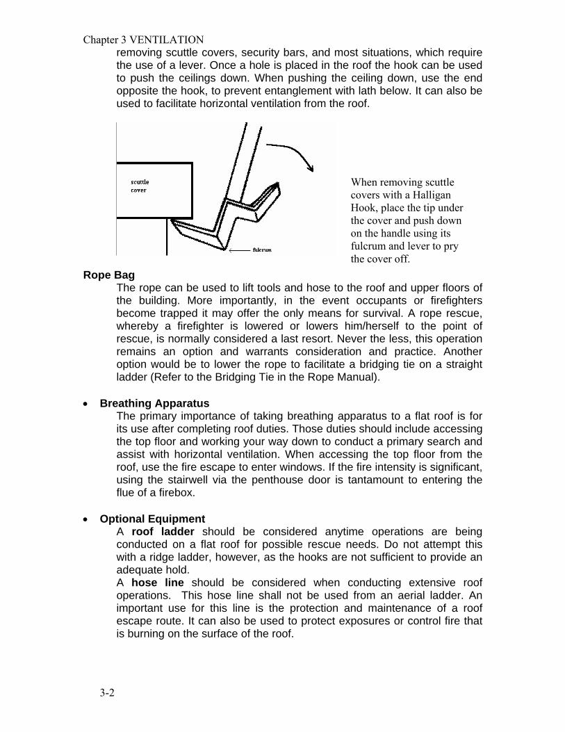
removing scuttle covers, security bars, and most situations, which require the use of a lever. Once a hole is placed in the roof the hook can be used to push the ceilings down. When pushing the ceiling down, use the end opposite the hook, to prevent entanglement with lath below. It can also be used to facilitate horizontal ventilation from the roof.
Rope Bag The rope can be used to lift tools and hose to the roof and upper floors of the building. More importantly, in the event occupants or firefighters become trapped it may offer the only means for survival. A rope rescue, whereby a firefighter is lowered or lowers him/herself to the point of rescue, is normally considered a last resort. Never the less, this operation remains an option and warrants consideration and practice. Another option would be to lower the rope to facilitate a bridging tie on a straight ladder (Refer to the Bridging Tie in the Rope Manual).
• Breathing Apparatus The primary importance of taking breathing apparatus to a flat roof is for its use after completing roof duties. Those duties should include accessing the top floor and working your way down to conduct a primary search and assist with horizontal ventilation. When accessing the top floor from the roof, use the fire escape to enter windows. If the fire intensity is significant, using the stairwell via the penthouse door is tantamount to entering the flue of a firebox.
• Optional Equipment A roof ladder should be considered anytime operations are being conducted on a flat roof for possible rescue needs. Do not attempt this with a ridge ladder, however, as the hooks are not sufficient to provide an adequate hold. A hose line should be considered when conducting extensive roof operations. This hose line shall not be used from an aerial ladder. An important use for this line is the protection and maintenance of a roof escape route. It can also be used to protect exposures or control fire that is burning on the surface of the roof.
When removing scuttle covers with a Halligan Hook, place the tip under the cover and push down on the handle using its fulcrum and lever to pry the cover off.

Chapter 3 VENTILATION
3-3
UDo not place any hose streams into ventilation openingsU. To do so will not only prevent products of combustion from exiting the building, it will push superheated gases and steam back onto firefighters and occupants.

Chapter 3 VENTILATION
3-4
FLAT ROOF OPERATIONS Most building fires will require the assignment of a roof team. This is particularly true of flat roofs. Duties performed on a flat roof will differ considerably than those for a peaked roof. When we go to a peaked roof we usually do so with the intention of cutting a hole in it. When the assignment is complete we vacate it and go on to perform other tasks. The ease of walking on a flat roof, the vantage point it offers, and building characteristics necessitate we conduct more extensive operations.
ROOF TYPES TIdentify the roof type if possibleT. Relay this information to the Incident Commander. Remember the roof types which spell early collapse.
LIGHTWEIGHT TRUSS CONSTRUCTION A truss is defined as a framed structure consisting of a triangle or group of triangles arranged in a single plane in such a manner that loads applied at the points of intersection of the members will cause only direct stresses (tension or compression) in the members. Loads applied between these points cause flexural (bending) stresses. Lightweight truss construction may only be able to withstand fire for five to ten minutes.
The critical areas in any structural framework are the points of connection. They are usually the first to fail during a fire. Gang nails hold the points of connection in lightweight trusses together. Since steel gang nails only penetrate the wood to a depth of 3/8 of an inch and is a conductor of heat, rapid failure should be anticipated.

Chapter 3 VENTILATION
3-5
Exposed, unprotected steel trusses, likewise, may begin to fail within this time frame. Recalling the Standard Time Temperature Curve (appendix A), firefighters would have to consider how long the fire has been burning and how much time, if any, they had left to operate on the roof. Heavy timber trusses, on the other hand, may be able to withstand a significant amount of fire but will give little or no warning when they collapse. Additionally, failure of heavy timber trusses, such as bowstring trusses, often involve more than one truss assembly. Many of the buildings with arch truss construction found in San Francisco have the truss assemblies spaced twenty feet on center. If only one truss should fail, forty feet of roof, and whoever is on top of it, will be lost. Six New York City firefighters were killed when the bowstring truss roof of a grocery store on which they were operating collapsed without warning. In Hackensack New Jersey, five firefighters operating underneath an bowstring truss roof were killed when it suddenly collapsed.
The components of these lightweight trusses consist of 2” x 4” top and bottom cords with metal tubing making up the web structure. Because of steels poor performance under fire conditions these trusses will fail rapidly.
Heat from a fire next door entered this exposure, raising ceiling temperatures well over 1000P
oPF. At this
temperature, steel begins to elongate and fail. In some types of construction the elongation of steel building components may be sufficient to push walls out, causing a collapse.

Chapter 3 VENTILATION
3-6
A humped roof identifies bow string trusses. The first and last truss is tied into the end walls by rafters. When an end truss fails the rafters tying it to the end wall will push the wall outward. Additionally, most openings (doors and windows) are located at the ends, thus weakening the walls. Another factor, particular to this building is the steel awning attached to the end wall creating additional stress. Positioning apparatus or personnel at this location may prove to be a fatal mistake.
Failure of this bowstring truss occurred at the location indicated by the circle. The truss does not need to burn completely through to initiate failure. As in this case, the bottom chord of the truss burned to a point it could no longer withstand the stresses placed upon it, then failed.

Chapter 3 VENTILATION
3-7
TSTANDARD CONSTRUCTION The majority of flat roofs in San Francisco are of standard construction. Rafters in these buildings will be of “2 by” construction. In other words 2” x 8”, 2” x 10”, 2” x 12”, and so on. These roofs usually give a warning of collapse such as sagging. Firefighters should be able to distinguish between the standard flat roof and an inverted roof. In the standard constructed flat roof, rafters are of larger dimension than the ceiling joists below them. For example, the rafters may be 2” x 12” while the ceiling joists may be 2” x 6”.
flat roof

Chapter 3 VENTILATION
3-8
Now imagine taking this assembly and inverting it so that the roof rafters are 2” x 6” and the ceiling joists are 2” x 12” InvertedT Construction
Generally, inverted roofs are constructed to provide a slight slope to allow for drainage, the smaller dimension rafters being easier to work with. Because the rafters are of smaller dimension the roof will tend to be “springy”. Do not read this as a spongy roof that needs to be vacated.

Chapter 3 VENTILATION
3-9
EXTERIOR FEATURES Often a glance at the building from the ground will provide some important information. The pattern of anchor bolts on the exterior wall of a building provides clues as to its construction. Anchor bolts (sometimes called tie rods) secure structural members such as rafters and joists to the exterior bearing wall.
Anchor bolts or tie rods fasten joists or rafters to exterior walls. Typically, the joist or rafter sets in a cavity within the wall, or sets on top of a ledger or corbel shelf. The joist or rafter is then secured to the wall providing additional stability.
The bolts in the row indicated by the letter “a” provide stability to the parapet wall, particularly in the event of an earthquake. A steel strap secured by the bolt near the top of the parapet is connected to the roof. The anchor bolts in row “b” secure the roof rafters to the wall. The distance between “a” and “b” give an estimate as to the height of the parapet wall. If the distance between “a” and “b” is great you may need a ladder to get from the top of the parapet wall to the roof. The anchor bolts in the row indicated by the letter “c” secure the ceiling joists to the wall. The distance between “b” and “c” indicates the approximate depth of the cockloft space. A shallow cockloft space (less than a foot deep) does not present as much of a fire spread hazard as a deeper one. The anchor bolts in row “d” secure the ceiling/floor joists to the wall. The area between “c” and “d” indicate the living space
Chapter 3 VENTILATION
3-10
OPERATIONS SAFETY CONSIDERATIONS • Check the roof for soundness. Before getting on roof make sure it is intact.
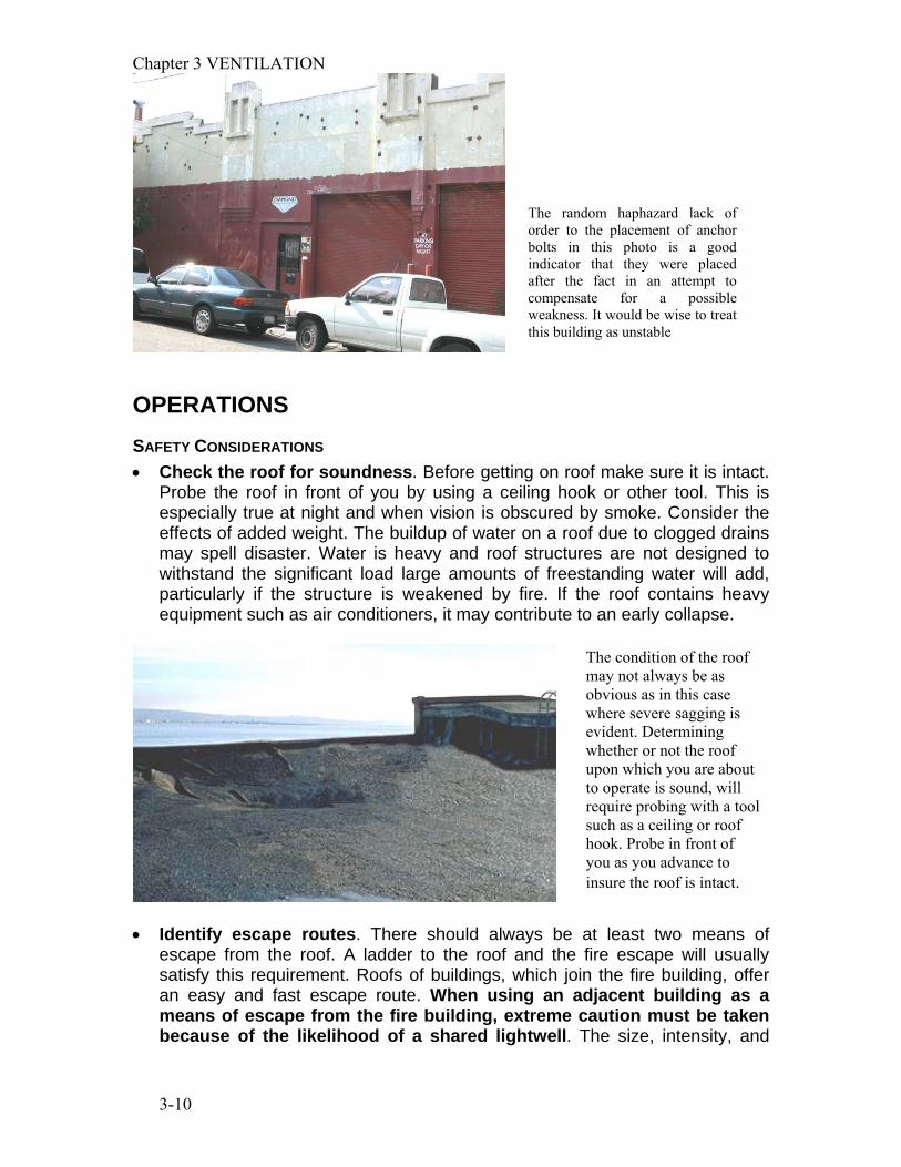
Probe the roof in front of you by using a ceiling hook or other tool. This is especially true at night and when vision is obscured by smoke. Consider the effects of added weight. The buildup of water on a roof due to clogged drains may spell disaster. Water is heavy and roof structures are not designed to withstand the significant load large amounts of freestanding water will add, particularly if the structure is weakened by fire. If the roof contains heavy equipment such as air conditioners, it may contribute to an early collapse.
• Identify escape routes. There should always be at least two means of
escape from the roof. A ladder to the roof and the fire escape will usually satisfy this requirement. Roofs of buildings, which join the fire building, offer an easy and fast escape route. When using an adjacent building as a means of escape from the fire building, extreme caution must be taken because of the likelihood of a shared lightwell. The size, intensity, and
The condition of the roof may not always be as obvious as in this case where severe sagging is evident. Determining whether or not the roof upon which you are about to operate is sound, will require probing with a tool such as a ceiling or roof hook. Probe in front of you as you advance to insure the roof is intact.
The random haphazard lack of order to the placement of anchor bolts in this photo is a good indicator that they were placed after the fact in an attempt to compensate for a possible weakness. It would be wise to treat this building as unstable
Chapter 3 VENTILATION
3-11
location of the fire will be the determining factor when establishing and identifying escape routes. Do not place all of your escape routes in one place. If that location becomes untenable or inaccessible due to changing conditions what will your alternative be? Place ladders well enough apart that they provide a means of egress from different portions of the roof.
NATURAL OPENINGS • Open penthouse doors. One of the first considerations when conducting
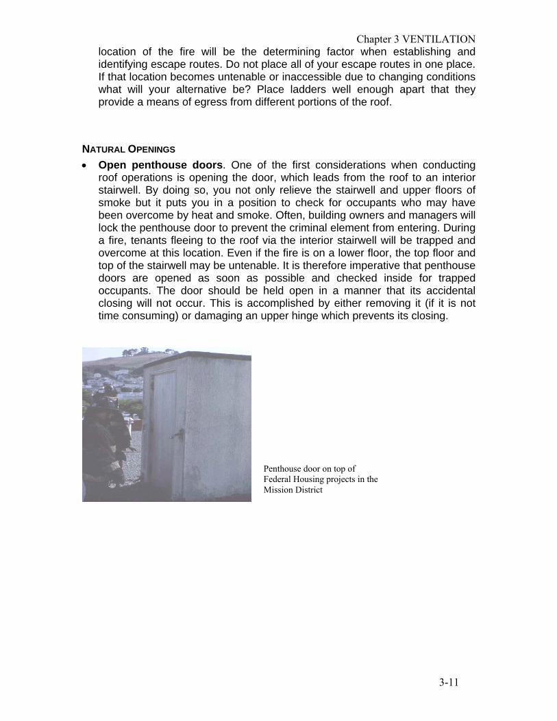
roof operations is opening the door, which leads from the roof to an interior stairwell. By doing so, you not only relieve the stairwell and upper floors of smoke but it puts you in a position to check for occupants who may have been overcome by heat and smoke. Often, building owners and managers will lock the penthouse door to prevent the criminal element from entering. During a fire, tenants fleeing to the roof via the interior stairwell will be trapped and overcome at this location. Even if the fire is on a lower floor, the top floor and top of the stairwell may be untenable. It is therefore imperative that penthouse doors are opened as soon as possible and checked inside for trapped occupants. The door should be held open in a manner that its accidental closing will not occur. This is accomplished by either removing it (if it is not time consuming) or damaging an upper hinge which prevents its closing.
Penthouse door on top of Federal Housing projects in the Mission District
Chapter 3 VENTILATION
3-12
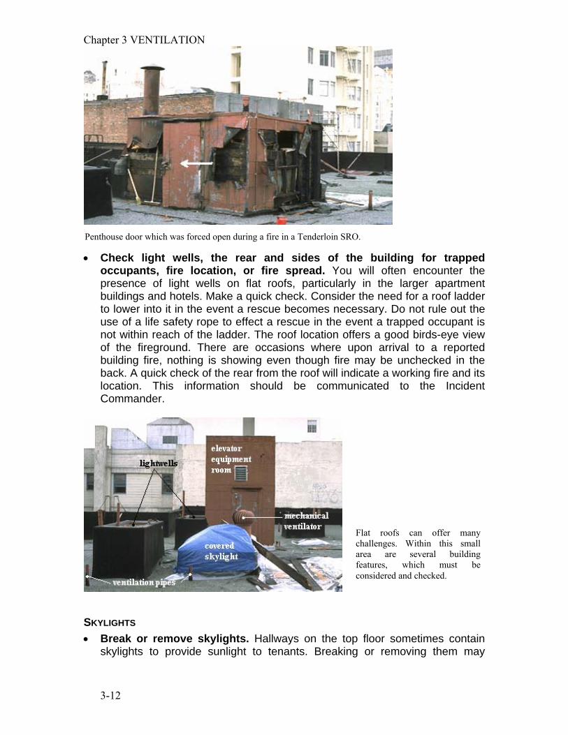
• Check light wells, the rear and sides of the building for trapped
occupants, fire location, or fire spread. You will often encounter the presence of light wells on flat roofs, particularly in the larger apartment buildings and hotels. Make a quick check. Consider the need for a roof ladder to lower into it in the event a rescue becomes necessary. Do not rule out the use of a life safety rope to effect a rescue in the event a trapped occupant is not within reach of the ladder. The roof location offers a good birds-eye view of the fireground. There are occasions where upon arrival to a reported building fire, nothing is showing even though fire may be unchecked in the back. A quick check of the rear from the roof will indicate a working fire and its location. This information should be communicated to the Incident Commander.
SKYLIGHTS • Break or remove skylights. Hallways on the top floor sometimes contain
skylights to provide sunlight to tenants. Breaking or removing them may
Penthouse door which was forced open during a fire in a Tenderloin SRO.
Flat roofs can offer many challenges. Within this small area are several building features, which must be considered and checked.

Chapter 3 VENTILATION
3-13
provide instant relief to occupants and firefighters alike. Careful removal of skylights to avoid or minimize damage can be time consuming. This method may be used, however, when time is not a factor. If a fire is of such magnitude that it requires immediate removal of the skylights, it is best to break them. If a skylight is removed it should be placed on its back. The fire does not have to be on the top floor to necessitate breaking of skylights. The trick when breaking them is to lightly strike a corner of the skylight with the pick of the ax or point of a Halligan tool, or break one small pane. Wait two or three seconds then break the skylight with heavier blows. The initial light blow will break small pieces of glass signaling firefighters below to prepare themselves for the much heavier blows to follow. Firefighters should attempt to pull skylight material onto the roof. All attempts should be made to prevent glass and debris from falling onto firefighters working below. Scuttle covers usually conceal a permanently fixed ladder, which leads from the top floor hallway or closet and terminates at the roof.
This view of a skylight was taken from the interior of a building at the top of a stairwell. Not every skylight contains the features shown. While operating from the roof you must, however, consider that these features may exist. As you can see, breaking the roof portion of the skylight will do little to relieve smoke on the top floor. You must also anticipate the presence of a draft stop and attempt to push it down or break it with a ceiling hook. Additionally, if fire is present or suspected in the attic or cockloft, the returns may have to be opened (sheetrock, lath and plaster, etc. removed) to check for its presence and to provide relief of the attic/cockloft space. Keep in mind that if fire is present in the attic and the returns are opened you will have in effect, placed a hole in the roof. Since only one hole should be placed in the roof you need to decide if this is where you want the hole. Note, the returns have been opened in this photo
The three skylights, indicated by the arrows, will greatly assist you in venting the upper floors. Use these features to your advantage. Before cutting a time consuming hole, break or open them.
Chapter 3 VENTILATION
3-14
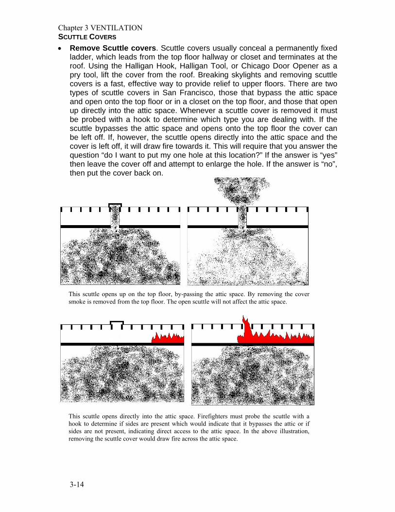
SCUTTLE COVERS • Remove Scuttle covers. Scuttle covers usually conceal a permanently fixed
ladder, which leads from the top floor hallway or closet and terminates at the roof. Using the Halligan Hook, Halligan Tool, or Chicago Door Opener as a pry tool, lift the cover from the roof. Breaking skylights and removing scuttle covers is a fast, effective way to provide relief to upper floors. There are two types of scuttle covers in San Francisco, those that bypass the attic space and open onto the top floor or in a closet on the top floor, and those that open up directly into the attic space. Whenever a scuttle cover is removed it must be probed with a hook to determine which type you are dealing with. If the scuttle bypasses the attic space and opens onto the top floor the cover can be left off. If, however, the scuttle opens directly into the attic space and the cover is left off, it will draw fire towards it. This will require that you answer the question “do I want to put my one hole at this location?” If the answer is “yes” then leave the cover off and attempt to enlarge the hole. If the answer is “no”, then put the cover back on.
This scuttle opens up on the top floor, by-passing the attic space. By removing the cover smoke is removed from the top floor. The open scuttle will not affect the attic space.
This scuttle opens directly into the attic space. Firefighters must probe the scuttle with a hook to determine if sides are present which would indicate that it bypasses the attic or if sides are not present, indicating direct access to the attic space. In the above illustration, removing the scuttle cover would draw fire across the attic space.

Chapter 3 VENTILATION
3-15
VENT CAPS Various types of ventilation pipes will usually be found at their termination point located on the roof. While caps placed over these vents have very little effect on air movement under normal conditions, they will seriously restrict the flow of hot gases and smoke under fire conditions. Popping the caps off is easy, usually requiring only one swing of the ax or other tool. Some ventilation caps are designed to move air. Often they are rotating types, which are affixed to the vent pipe. Let them perform the function they were designed to do unless it is drawing heat and smoke to an area you do not want. If it is drawing heat and smoke to an area that you do not want it to, disable the rotating vent by giving it a hit with an axe or tool. Do not attempt to remove the cap of a rotating vent. It is very difficult and is time consuming.
CUTTING CONSIDERATIONS • Cut a hole in the roof. Normally this function is performed when the fire is
located on the top floor or in the attic space. Providing a hole in the roof will not only allow the relief of hot smoke and gases, but in the event a backdraft or flashover occurs, a considerable amount of the energy released will be directed upward, into the atmosphere, away from firefighters and occupants below. When fires are located on lower floors, cutting a hole in the roof will be ineffective and unnecessarily time consuming. Of course there are always exceptions. In balloon-framed buildings, fire will rapidly run the walls and find its way to the attic in addition to running the floor spaces. Even if a fire is in the basement of one of these structures, it is imperative that the roof is opened. Occupied places of assembly such as supper clubs, if involved in fire will require extensive roof operations. The Beverly Hills Supper Club fire in May, 1977 serves as a good example of how critical vertical ventilation is with this type of occupancy. While more than five hundred firefighters were committed to this fire, no one considered opening the roof. All efforts were directed at rescue and extinguishment. 164 lives were lost.
Do not walk on top of scuttle covers. They are not designed to carry your weight. Never attempt to access the top floor via the scuttle. If the fire suddenly blows, the energy will be directed through this opening causing serious or fatal injuries. There is also the possibility of getting trapped in a closet, which may be locked.

Chapter 3 VENTILATION
3-16
Cutting a hole in the roof will draw fire to that point. For that reason only one hole should be made.
More than one hole only “confuses” the fire and results in greater extension. To minimize the possibility of drawing fire and smoke throughout the building the ventilation hole should be placed directly over the fire or as close as is practical. Remember to allow a margin of safety, particularly when considering the collapse
In the first illustration a hole is correctly placed over the attic fire. In the event more ventilation is required the hole should be enlarged. A second hole will encourage fire to spread towards it. Invariably the mistake is continued until the entire attic space is involved with fire as indicated in the third illustration.

Chapter 3 VENTILATION
3-17
potential presented by lightweight truss construction. For this reason, if cutting a hole in a roof with truss construction the hole should not be directly over the fire. Determining the location of the ventilation hole is usually as simple as looking at the fire and cutting a hole directly above it. Sometimes, however, the fire may not be visible. Communication with personnel operating inside may help in your determination. The following are other indicators, which may be of assistance:
• Tar which is bubbling or melting • In rainy weather, the presence of water vapor in a portion of the roof • Soil pipes which are hot to the touch
In the event you are unsure as to fire location a simple method of estimating will help you locate the proper position for a hole. When you arrive at the roof, mentally divide it into quadrants. You should be able to estimate what quadrant the fire is under. Place the hole in the middle of the quadrant. When placing a hole in a roof, the object is to cut and remove the deck while leaving the roof supports (rafters) intact. Inadvertently cutting the support system may lead to a collapse of the roof. In some instances the roof covering may have to be removed prior to cutting the deck. This is particularly true when the covering has been built up with layers of asphalt impregnated felt paper and tar over many years (see illustration). With a heavily built up roof, the consequences of trying to cut the sheathing and the covering in one swipe of the rotary or chain saw will be a gumming up of the blade resulting in failure of the saw to cut.
One method to use when placing a hole in a roof with a heavily built up covering is to remove the covering first with an ax, then, using a power saw, cut the sheathing. If the roof has only one or two coverings it may not be necessary to remove the covering first. In this instance a single pass with the saw may be sufficient to penetrate both the covering and the deck without gumming up the saw. The use of a rotary saw with 12-point carbide tip blades makes it unnecessary to use an axe to remove built up roof coverings prior to cutting the roof deck. These saw blades will easily penetrate all layers of roof covering and the roof deck in one pass, including heavily built-up roofs. Once the location of the hole is determined and you are about to begin your cut it is ideal to start with your back to the wind and continue working towards the direction from which the wind is coming. This will keep you out of the smoke as much as possible. Once the cuts are complete, the deck will have to be removed.

Chapter 3 VENTILATION
3-18
How it is removed will depend on the type of decking used. Older roofs which use “one by” are easier to remove than decking constructed of plywood. The reason is the number of nails, which must be overcome when pulling on the deck. See the following illustration.
When pulling “one by” decking, it will only be necessary to overcome several nails per board. The operation will be rapid. On the other hand, with a plywood deck, trying to remove the one large section will be almost impossible. By dividing it into more manageable sections the operation is made easier. To facilitate pulling of the roof deck the saw operator should provide “knockouts” at the corner or corners of the sections to be pulled. This will allow firefighters with hooks to get the end of the tool below the roof deck.

Chapter 3 VENTILATION
3-19
The hole should be 4’ by 4’. In the event more ventilation is required, expand the hole. DO NOT CUT MORE THAN ONE HOLE! The following diagram illustrates the procedure for expanding the hole.
This photograph illustrates proper placement of the Halligan Hook into a knockout provided for pulling a roof deck. An upward motion with the handle will provide tremendous lifting power. The Halligan Hook, with its long handle and strategically placed fulcrums, make it an excellent prying tool.

Chapter 3 VENTILATION
3-20
Recommended sequence for cuts
When making initial cuts, extend the “legs” four feet. Don’t forget to make a
“knockout” in one corner to allow a purchase point for the Halligan Hook. If after the deck is pulled and ceiling pushed down the hole needs to be expanded all
that is required is two more cuts indicated by broken lines. This will give you an 8’ by 8’ hole.
1
2
3
4
5
66 7
8
9
10
This photo was taken at the scene of a 2-alarm fire in the Mission district. The ventilation hole is not only a good size but also spans two areas, whichneeded venting. The hole straddles a wall, whichseparates a fire compartment and a stairwell. Two critical areas benefited from this operation, the fire area and the means of egress for occupants. The crew who placed this vent was well in tune with the job at hand and an understanding of the construction features of this particular building.
Chapter 3 VENTILATION
3-21
Whenever you place a hole in the roof or cause an opening to be made in the roof (break a skylight, open a scuttle cover, etc.) it is imperative that you do not get into a position where the opening is between you and your escape route. This could prove to be a fatal mistake!
TRENCH CUT A form of vertical ventilation not often considered but having the potential for great success is the trench cut, sometimes referred to as the strip cut. This tactic should be considered under the following situations:
• There is a large volume of fire in the attic or cockloft • Several rooms or a large area of the top floor are involved with fire
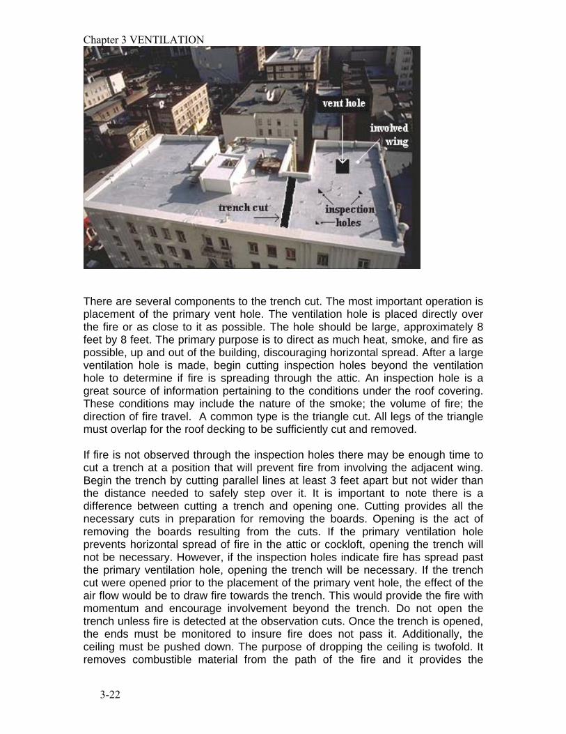
The purpose of the trench is to cut off extension of a fast moving attic or cockloft fire from uninvolved portions of the building. The trench cut is a furrow, hole or strip, which extends from one wall or fire separation to another. Full advantage of the building’s construction and configuration should be utilized. This would include parapets, firewalls, light well, elevator and stair shaft separations. The following photograph depicts a typical trench cut placed to prevent fire from extending from the involved wing to the remainder of the cockloft or attic.
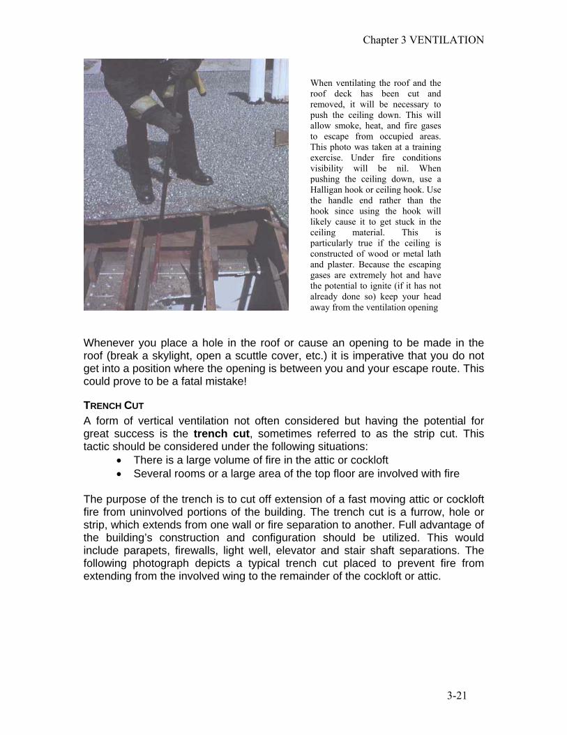
When ventilating the roof and the roof deck has been cut and removed, it will be necessary to push the ceiling down. This will allow smoke, heat, and fire gases to escape from occupied areas. This photo was taken at a training exercise. Under fire conditions visibility will be nil. When pushing the ceiling down, use a Halligan hook or ceiling hook. Use the handle end rather than the hook since using the hook will likely cause it to get stuck in the ceiling material. This is particularly true if the ceiling is constructed of wood or metal lath and plaster. Because the escaping gases are extremely hot and have the potential to ignite (if it has not already done so) keep your head away from the ventilation opening
Chapter 3 VENTILATION
3-22
There are several components to the trench cut. The most important operation is placement of the primary vent hole. The ventilation hole is placed directly over the fire or as close to it as possible. The hole should be large, approximately 8 feet by 8 feet. The primary purpose is to direct as much heat, smoke, and fire as possible, up and out of the building, discouraging horizontal spread. After a large ventilation hole is made, begin cutting inspection holes beyond the ventilation hole to determine if fire is spreading through the attic. An inspection hole is a great source of information pertaining to the conditions under the roof covering. These conditions may include the nature of the smoke; the volume of fire; the direction of fire travel. A common type is the triangle cut. All legs of the triangle must overlap for the roof decking to be sufficiently cut and removed. If fire is not observed through the inspection holes there may be enough time to cut a trench at a position that will prevent fire from involving the adjacent wing. Begin the trench by cutting parallel lines at least 3 feet apart but not wider than the distance needed to safely step over it. It is important to note there is a difference between cutting a trench and opening one. Cutting provides all the necessary cuts in preparation for removing the boards. Opening is the act of removing the boards resulting from the cuts. If the primary ventilation hole prevents horizontal spread of fire in the attic or cockloft, opening the trench will not be necessary. However, if the inspection holes indicate fire has spread past the primary ventilation hole, opening the trench will be necessary. If the trench cut were opened prior to the placement of the primary vent hole, the effect of the air flow would be to draw fire towards the trench. This would provide the fire with momentum and encourage involvement beyond the trench. Do not open the trench unless fire is detected at the observation cuts. Once the trench is opened, the ends must be monitored to insure fire does not pass it. Additionally, the ceiling must be pushed down. The purpose of dropping the ceiling is twofold. It removes combustible material from the path of the fire and it provides the
Chapter 3 VENTILATION
3-23
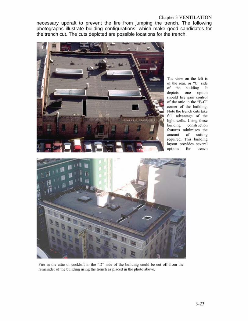
necessary updraft to prevent the fire from jumping the trench. The following photographs illustrate building configurations, which make good candidates for the trench cut. The cuts depicted are possible locations for the trench.
The view on the left is of the rear, or “C” side of the building. It depicts one option should fire gain control of the attic in the “B-C” corner of the building. Note the trench cuts take full advantage of the light wells. Using these building construction features minimizes the amount of cutting required. This building layout provides several options for trench
Fire in the attic or cockloft in the “D” side of the building could be cut off from the remainder of the building using the trench as placed in the photo above.

Chapter 3 VENTILATION
3-24
This aerial view was taken from the rear. From the front of this building it would not be apparent its configuration consists of 4 wings. Fire involving the attic in any of these wings could be cut off from the remainder of the building with minimal cutting. It is imperative firefighters assigned to the roof recognize this construction feature, and if the situation dictates, use it to their advantage. The light wells, forming the wings, are used to full advantage.
Buildings, like the one above, have an extensive attic or cockloft space. If unchecked, fire at one end of the attic will eventually consume the entire space. The trench cut is a tactic, which may prevent a loss of this nature. Consider using it when fires involve attics and cocklofts with large spaces. Buildings, which are typically good candidates for the trench cut, are “U” frame, “W” frame, “O” frame, “L” frame, and etc. In other words, when viewed from the air, the configuration of the building roughly resembles these letters. The building above would be called an “L” frame.
Chapter 3 VENTILATION
3-25
The trench cut is a labor-intensive operation, which requires coordination of roof personnel as well as those inside the building. Firefighters on the top floor should be pulling ceilings and extinguishing fire from below.
PEAKED ROOF OPERATIONS Peaked roofs are designed to shed rain and at the same time offer an esthetically pleasing appearance. Because of their pitched or sloped surface, in general, they are structurally less sound than a flat roof. When a structure’s top floor and/or attic space is involved with fire, vertical ventilation must be considered. Difficulty in accessing and maneuvering on peaked roofs limits the amount of work and types of tasks that can be accomplished. When the decision is made to open a peaked roof the game plan is get on the roof, cut a hole, and get off. Prior to actually getting on the roof try to determine its integrity. Unless you have pre-fire planned the structure your assessment will be based on experience and education. Consider the following:
• Roof rafter support system • Roof slope • Roof shingle surface
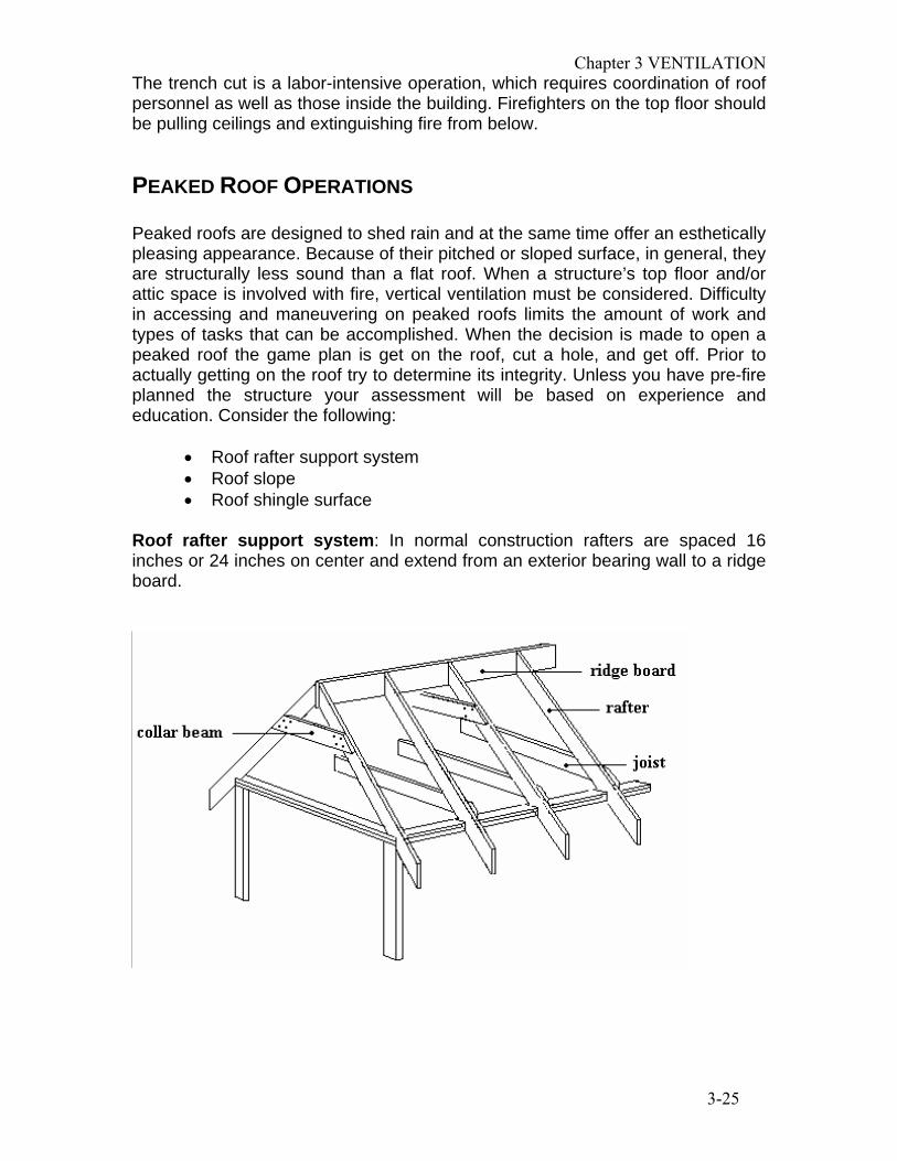
Roof rafter support system: In normal construction rafters are spaced 16 inches or 24 inches on center and extend from an exterior bearing wall to a ridge board.

Chapter 3 VENTILATION
3-26
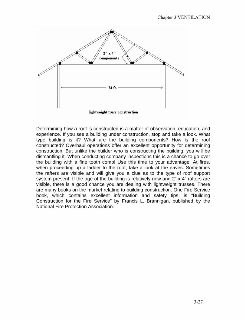
Truss construction is designed according to engineering principles so it can support loads over a wide span.
The dimensions of roof support system components, where normal construction has been used, will be larger than if truss construction was used in its place. Looking at the following two diagrams, it can be seen that if a roof is to span 24 feet, normal construction will require at least one column or wall to support the span. In this instance, the placement of one column or wall will require the ceiling joist be at least 2” x 12”. Using engineered construction (trusses), no supporting column or wall is required. The dimensions of the lumber used are significantly smaller than that used in normal construction. Normal construction, with its heavier material and design, is more stable and will better withstand the ravages of fire.
Chapter 3 VENTILATION
3-27
Determining how a roof is constructed is a matter of observation, education, and experience. If you see a building under construction, stop and take a look. What type building is it? What are the building components? How is the roof constructed? Overhaul operations offer an excellent opportunity for determining construction. But unlike the builder who is constructing the building, you will be dismantling it. When conducting company inspections this is a chance to go over the building with a fine tooth comb! Use this time to your advantage. At fires, when proceeding up a ladder to the roof, take a look at the eaves. Sometimes the rafters are visible and will give you a clue as to the type of roof support system present. If the age of the building is relatively new and 2” x 4” rafters are visible, there is a good chance you are dealing with lightweight trusses. There are many books on the market relating to building construction. One Fire Service book, which contains excellent information and safety tips, is “Building Construction for the Fire Service” by Francis L. Brannigan, published by the National Fire Protection Association.

Chapter 3 VENTILATION
3-28
Roof slope: The slope of the roof will, in large part, determine the ease in walking on its surface. The slope or pitch as it is sometimes called is expressed as the number of inches of vertical rise in 12 inches of horizontal run. If a roof rises 4 inches within this 12-inch run, the pitch of the roof is expressed as 4 in 12.
When a roofs pitch exceeds 4 in 12, walking becomes difficult. Use of a roof ladder will be necessary. Ideally, the roof ladder should be long enough so that when the hooks are over the ridge, the base of the ladder reaches to and rests on the bearing wall. In this case the ladder not only provides footing but also in the event the roof deck collapses the ladder will stay intact, the ridge board and bearing wall providing support. If the roof is of truss construction and the roof deck collapses, the lack of a ridge board will cause the ladder and anyone on it to fall into the inferno below. If it is necessary to leave the safety of a roof ladder, straddle the peak while walking or while sitting and scooting across. When walking on a sloped roof do not walk using a normal heel-toe foot action, rather, walk flat-footed. Also, in order to quickly shift your body weight and to compensate for the uneven surface of the roof, bend both legs at the knees. You should not walk straight down the slope of a roof but rather walk across it at an angle. When walking towards the edge of a roof do so very carefully. At normal walking pace, the weight of equipment and protective clothing can increase your forward momentum and prevent you from stopping at the edge of the roof. Deterioration of the roof deck and eaves will occur over a period of time when subjected to constant moisture, insects or neglect. While rotting may occur anywhere, the areas where it occurs most often are the roof edges, where the roof changes slope, and where a sloping roof abuts a vertical plane such as an additional story. Do not rely on chimneys or soil pipes to grab for stability or security. Often, they are in such a deteriorated state that your weight alone will be sufficient to cause them to fail.

Chapter 3 VENTILATION
3-29
Roof shingle surface. The material with which the roof’s surface is composed must also be considered. Composition shingles allow better footing than a slate roof. Slate and tile roofs are slippery particularly when wet. Any roof covering which receives a substantial amount of moisture and little sunlight tends to grow moss. This makes for a very slick surface. Metal roofs can also be treacherous when wet. Shakes, tiles, and slate, over time, may also loosen, providing for very unstable footing. When sizing up a roof, it will also be necessary to take into consideration the weight of the surface material. Slate and tile roofs are extremely heavy. At best, the builder provided the minimum size roof support system allowed by code. Or perhaps the homeowner replaced the old composition shingle, which is relatively light, with a slate roof without compensating for the added stress. Composition shingle, roll roofing,and tar and gravel can be easily cut using an ax or power saw. Tile and slate on the other hand must be broken and removed before a saw or ax can penetrate the wood deck. A flat head ax, sledgehammer or mall is sufficient for breaking this material. If you are presented with a slate or tile roof the additional time element required to open it must be taken into account. Accessing and working on peaked roofs. Once the decision is made to open the roof you must decide how to access it. Peaked roofs are dangerous and the best way to avoid falling off of one or into a collapse is to work from an aerial ladder. You must be secured by a safety strap and have communication with the aerial operator. Today’s aerial ladders are designed to operate from 0 P
oP
(horizontal) to 85P
oP (nearly vertical). With this in mind, working on a one-story
building should pose no problem for the ladder. In the event an aerial ladder is not practical, ground and roof ladders should be used. Ladder from a safe area, generally the area opposite from where you will be making your cuts. In the event you need to rapidly exit the roof you will be escaping to safety and an area that is sounder. Ideally, you want at least two ways off the roof. This may not always be possible so it is imperative that you and your partner pay close attention to the developing situation. Base your decisions on what is occurring and what is likely to occur.

Chapter 3 VENTILATION
3-30
Additionally, provide safety measures such as a firefighter with charged hoseline who can monitor the situation and provide you with protection. Avoid positioning a ladder over a window, but if left with no choice consider positioning a charged hose line at this position to protect firefighters. Once on the roof, the decision as to where to open up must be based upon fire location and roof construction. Open up as close to the seat of the fire as possible keeping in mind that truss roof construction will require backing off a distance to compensate for the possibility of partial roof collapse. Normally, venting a peaked roof does not occur unless the fire is on the top floor and/or attic space. An exception would be balloon frame construction. In this case the roof would have to be open regardless of the fire location. Look for indicators, which will assist you in choosing the location. Some of the signs, which will pinpoint the location of the fire, are:
• bubbling roof tar • smoke pushing from shingles • “steam” rising from a specific location during rainy or wet
conditions • the obvious location of the fire itself as indicated by flames
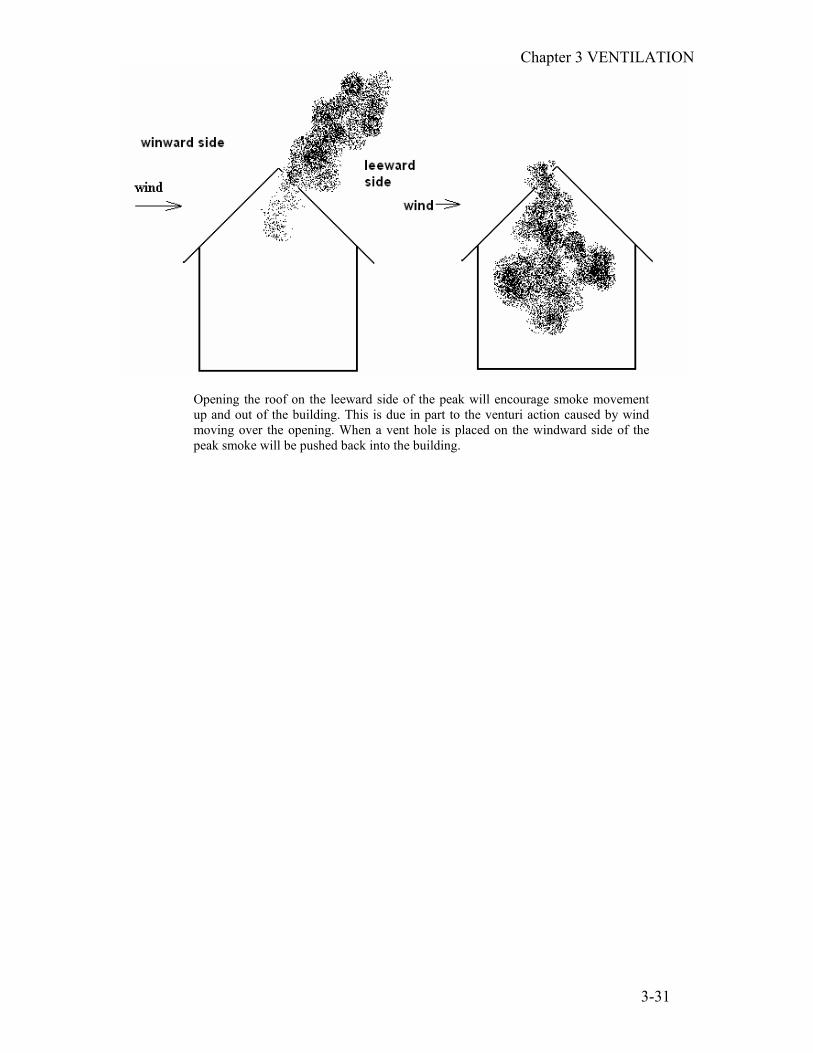
issuing from windows and/or roof vents The side of the roof peak where the vent hole will be placed is usually determined by the direction of the wind. The vent hole should be placed on the leeward side of the peak.
This photo illustrates the need to provide more than one exit from a roof. These firefighters have been cut off. Do you think a hose line positioned at this location would make a difference? Photo by Juan Perez, CFPA Reprinted with permission of American Fire Journal
Chapter 3 VENTILATION
3-31
Opening the roof on the leeward side of the peak will encourage smoke movement up and out of the building. This is due in part to the venturi action caused by wind moving over the opening. When a vent hole is placed on the windward side of the peak smoke will be pushed back into the building.

4-1
CHAPTER 4 HORIZONTAL VENTILATION The type of ventilation most often used by firefighters is through horizontal openings such as windows and doors. The majority of fires we respond to are small in nature, lacking the thermal energy necessary to give smoke its buoyancy and therefore will not require vertical ventilation. The simple act of opening a window may be sufficient enough to provide adequate ventilation. Indiscriminate breaking of windows, however, may increase the fire’s intensity and redirect it to an undesirable location. At the very best, it is unprofessional. The damage created by venting efforts should be proportionate to the damage being inflicted by the fire. In other words, a small mattress fire, pot on a stove, or waste basket fire will not require the breaking of windows or the cutting of a hole in the roof. In more serious fires, hose lines put into operation create large volumes of steam and push heat, smoke, and other products of combustion in front of it. Horizontal ventilation provides an exit path for this deadly concoction. Breaking of windows in this situation would be appropriate. It is very important to note that any living thing between the fire and exit point will be critically burned or killed once the nozzle comes into play. With this in mind, it is important these areas are either searched for victims prior to the application of water or that it has been ascertained no humans are occupying this area. This requires communication and coordination by the Incident Commander between the fire attack and ventilation groups.
Horizontal ventilation can be accomplished from outside the building or from within. When venting, make sure the openings are planned and systematic. Ventilation should be conducted in a coordinated effort with the engine company operating the attack line. This is best accomplished by communicating with the radio. It may also be accomplished by visual observation and listening for the sound of hose streams. Venting prior to having a hose line in place may increase fire activity resulting in serious injuries to firefighters and/or civilians. Venting too late may cause smoke, steam, and other products of combustion to expand and spread into areas which were previously smoke-free.
OUTSIDE VENTING Horizontal venting from the outside occurs when we open doors and windows from the exterior of the building. This may involve forcible entry and the breaking of windows with aerial ladders, ground ladders, or hand tools such as axes, Halligan tools, or ceiling hooks. Ground ladders may be used for venting windows by positioning the ladder at the window sill then extending it several rungs until it reaches the top of the window pane. While footing the ladder and checking to see that it is clear below, remove the ladder from the sill one or two feet and drop it into the window. Firefighters must also take precautions to guard against flying glass by wearing proper protective clothing including eye protection, helmet, and gloves.

Chapter 4 Horizontal Ventilation
4-2
When using axes, ceiling hooks, or other tools to break windows, stand to the side (upwind if possible) and with the handle held higher than the head of the tool to prevent glass sliding down it. Strike the upper portion of the window. If the window to be broken is above grade level it will be necessary to raise a ladder in order to reach it. The ladder should be raised to the side of the window (upwind if possible), and Unot U to the sill. Windows can often be reached from stairs, fire escapes, and even the roof. All too often the roof is thought of as a place where only vertical ventilation occurs. It also affords an excellent location to conduct horizontal ventilation, particularly at top floor fires. A short length of rope with a Halligan tool or Chicago Door Opener is the ideal tool in this situation.
When venting windows from the outside, the first one to break is the one to where the nozzle is pushing the fire, steam, and products of combustion. If you
Halligan tools are manufactured with a loop located at the fork end of the tool. The loop allows a rope to be tied or clipped to it. Firefighters assigned to truck companies should carry a 25-foot length of rope, preferably with clips at each end, to facilitate quick attachment.
Once the rope has been clipped or tied to the Halligan tool or Chicago Door Opener, it is lowered over the parapet wall until it reaches the level of the windows to be broken. With one hand, grasp the rope tightly, not letting it go or moving the position of your hand. With your other hand, raise the tool back to you. Once completed, with your free hand, take the tool and throw it out away from you. The flight of the tool will stop once the end of the rope is reached (the hand grasped to the rope). The arc of the flying tool will take it directly into the window breaking it. Maintaining your grasp on the rope, retrieve the tool with your free hand and move on to the next window. Continue venting.

Chapter 4 Horizontal Ventilation
4-3
are in doubt, go for the window that looks like it will fail soonest-the one most seriously exposed from the inside. Once these windows are vented, continue with the flanks (adjacent areas where the nozzle and hose team are moving through).
When cross ventilation can be accomplished, windows on the leeward side should be opened first followed by windows on the windward side.
In this scenario assume the main body of fire is located within the general area indicated by the circle. The nozzle is pushing fire, heat, smoke, steam, and products of combustion towards the windows indicated by the numbers 1. If venting first occurred at the area indicated by the “X”, not only would little ventilation occur, but smoke, steam, and products of combustion would be spread throughout the building. If venting first occurred at the windows indicated by the numbers 1, and then laterally as indicated by the arrows, the majority of the fire’s by-products will be immediately pushed out of the building, using the shortest route possible.

Chapter 4 Horizontal Ventilation
4-4
PRESSURIZED VENTILATION Traditionally, the Fire Service employed the use of electric powered fans toU pull U smoke out of a building. This is called negative pressure ventilation. The fan was usually placed in a window with the fan exhausting the contaminated atmosphere to the outside.
Positive Pressure Ventilation is a ventilation tactic, which gained recognition in the 1980’s due in large part to the efforts of the Los Angeles City Fire Department. Positive Pressure Ventilation, or more commonly referred to as PPV, is a form of mechanical ventilation, which uses large gas, hydraulic, or electric powered fans to create an atmosphere within a compartment (building, room, etc.), whose pressure is greater than that of the surrounding areas. The positive pressure created by these fans Upushes U smoke out of selected openings. The deployment of PPV fans differs from that of the more traditional negative pressure fans as they are placed outside of the area to be ventilated with the airflow directed into it.
Negative Pressure. The traditional method of negative pressure ventilation pulls the contaminated atmosphere from the building, creating a pressure less than the surrounding area, which exhausts the smoke to the outside.
Chapter 4 Horizontal Ventilation
4-5
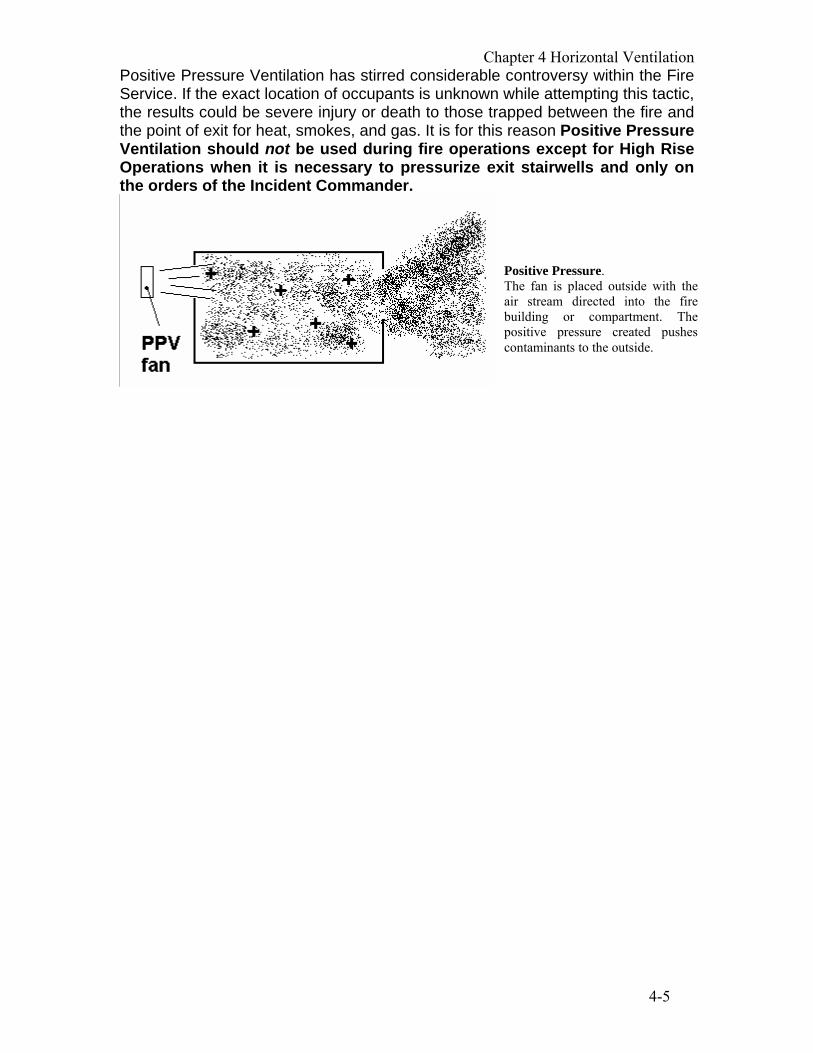
Positive Pressure Ventilation has stirred considerable controversy within the Fire Service. If the exact location of occupants is unknown while attempting this tactic, the results could be severe injury or death to those trapped between the fire and the point of exit for heat, smokes, and gas. It is for this reason Positive Pressure Ventilation should not be used during fire operations except for High Rise Operations when it is necessary to pressurize exit stairwells and only on the orders of the Incident Commander.
Positive Pressure. The fan is placed outside with the air stream directed into the fire building or compartment. The positive pressure created pushes contaminants to the outside.


5-1
CHAPTER 5 SPECIAL VENTILATION OPERATIONS
HIGH RISE BUILDINGS VENTILATION Normally we consider smoke to be hot and therefore lighter than the surrounding air. The rising smoke is generally vented when we open a hole in the roof or open windows on the upper floors. This is by far, the scenario we most often encounter. High Rise fires, however, present us with a far more complex situation. In high-rise fires, there are factors that affect smoke movements that we will not encounter in buildings, which are relatively lower in height. The movement of smoke throughout a high-rise building is influenced by Passive and Active factors.
ACTIVE FACTORS
The four active factors are dynamic and change constantly throughout the fire. A. Thermal Energy B. Stack Effect C. Wind D. Heating, Ventilating, and Air Conditioning Systems
TTHERMAL ENERGY T
Thermal Energy of a fire causes the gases in the vicinity of the fire to expand, become buoyant, and rise. As the smoke and gases move away from the fire area, the thermal energy imparted by the fire is lost to the surroundings. The smoke and gases contract to their original volume and become denser. T
STACK EFFECT
Stack Effect is the vertical natural air movement through the building caused by the differences in temperature and densities between the inside air and outside air. Under normal conditions, the stack effect accounts for most of the natural air movement in high-rise buildings. It is responsible for a significant amount of smoke movement in a high-rise building fire. The magnitude of stack effect is a function of building height, air tightness of exterior walls, air leakage between floors, and the difference in temperature between inside air and outside air. As was mentioned earlier, the temperature of smoke and fire gases decreases rapidly as they move farther away from the fire area. The influence of the heat and pressures of the fire are significant in the vicinity of the fire itself, and are important because of the expansion of air. However, as the height of the building increases and the difference between the inside temperature and the outside temperature widens, the stack effect plays a more pronounced role in smoke movement.

5-2
Vertical air movement from the ground floor to the roof characterizes Positive Stack Effect. The colder the weather and the higher the building, the more significant are the effects of a positive stack. As long as the air inside the building is warmer than the atmospheric air outside the building, ventilation will occur by having fresh air drawn in through lower building openings and discharged above the neutral pressure plane (see figure 1). This is due to the greater difference in temperatures between outside and inside air.
Figure 1
Negative stack effect can occur in reverse directions in warm climates but is not as dramatic because the difference in temperature is not as great. As the smoke leaves the fire area, usually by way of the stair shafts and other vertical openings, it cools. Negative stack pushes the smoke down the vertical shafts, or it settles to floors below the fire. This situation may cause Staging to be relocated farther from the fire, or cause firefighters trying to reach the fire floor to use breathing apparatus earlier than desired. (See figure 2)
Positive stack is characterized by a strong draft from the ground floor to the roof. Airflow will be inward below the neutral pressure plane and outward above the neutral pressure plane. Positive stack occurs when the outside air temperature is lower than the inside air temperature. The greater the temperature differential the greater the effect.

Chapter 5 Special Ventilation Operations
5-3
Figure 2
UIt is important to remember that stack effect may violently draw the fire toward the open doorway of a smoke proof tower if it is used as the attack stairwell driving back attacking hose lines U.
NEUTRAL PRESSURE PLANE
DEFINITION “The level within a building at which the barometric pressures both inside the building and outside the building are equal. The Neutral Pressure Plane may extend over several floors"
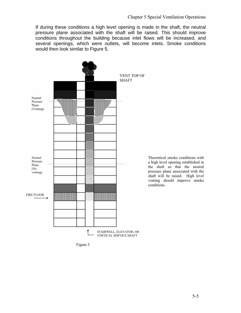
When considering smoke movement and ventilation of high rise buildings the location of the neutral pressure plane is of great significance. Assuming that a fire occurs on a low floor of a high-rise building and that the outside temperature is lower than the inside temperature, the natural smoke movement would be similar to that in Figure 4. Smoke would also occur on floors immediately above the fire due to fire pressure and floor leakage. The three floors above the fire and the top three floors of the building (including the stairwells in these areas) must be searched for trapped occupants and smoke.
Negative stack Is characterized by air movement inward above the neutral pressure plane and outward below the neutral pressure plane. Negative stack occurs when the outside air temperature is greater than the inside. Negative stack is usually less dramatic than positive stack.

5-4
When considering smoke movement in this situation, it can be seen that the most hazardous areas include the floor directly above the fire and the top floors (also know as ‘mushrooming’). Smoke may become untenable in these areas yet remain tenable on floors near the neutral pressure plane.
FIRE FLOOR
STAIRWELL, ELEVATOR, OR VERTICAL SERVICE SHAFT
Neutral Pressure Plane
Figure 4
Chapter 5 Special Ventilation Operations
5-5
If during these conditions a high level opening is made in the shaft, the neutral pressure plane associated with the shaft will be raised. This should improve conditions throughout the building because inlet flows will be increased, and several openings, which were outlets, will become inlets. Smoke conditions would then look similar to Figure 5.
Neutral Pressure Plane (No venting)
FIRE FLOOR
STAIRWELL, ELEVATOR, OR VERTICAL SERVICE SHAFT
VENT TOP OF SHAFT
Neutral Pressure Plane (Venting)
Figure 5
Theoretical smoke conditions with a high level opening established in the shaft so that the neutral pressure plane associated with the shaft will be raised. High level venting should improve smoke conditions.

5-6
PRESSURE DYNAMICS (WIND)
Wind can have a major effect on smoke movement in high-rise buildings. Wind can override all the other factors of smoke movement. Figure 3 illustrates the air pressure distribution along the four sides and the roof of a building.
Figure 3
ELEVATION (Side) PLAN(Top) The plan view of the pressures shows that the windward wall is subjected to an inward pressure, while the leeward wall and the two side walls have an outward pressure (suction). The flat roof (elevation view) has an upward pressure, with the maximum amount occurring at the windward edge. The effect of wind pressures and suctions modifies the natural air movement within a building. For example, the negative pressure on the roof of a tall building has an aspirating effect on a vertical shaft opened at roof level. Horizontal pressures and suctions cause the neutral pressure planes in exterior walls to move. Positive wind pressure would tend to raise the neutral pressure plane, while negative pressures will lower it.
WIND

Chapter 5 Special Ventilation Operations
5-7
HVAC
Correct use of the heating, ventilating, and air conditioning (HVAC) system can limit the spread of smoke throughout the building, and improve conditions within the building for occupants as well as firefighters. It is essential that firefighters have a basic understanding of HVAC systems and how they work. HVAC systems are divided into three subsystems as follows: • The Processing System • The Supply System (Distribution) • The Return System
The TProcessing SystemT is usually installed on the floors of the building where the mechanical equipment rooms (MER) are located. The following equipment for the processing of the air will be found on the MER floor (Figure 7): 1. Outside air supply dampers 2. Equipment for the heating, cooling, filtering, and humidification of the air 3. Supply air fans 4. Smoke and/or heat detectors 5. Duct work to the supply air shaft 6. Duct work from the return air shaft 7. Return air fans 8. Exhaust air dampers 9. Mixing dampers
Figure 7

5-8
TSupply systemT components consist of: 1. A supply air shaft 2. Fire Dampers 3. Supply air ducts 4. Air diffusers
Air is distributed to all floors via the supply airshaft. Air from the supply airshaft is distributed on the floor by ducts. The ducts are located in the plenum. Fire dampers will be found in these ducts where ducts meet the supply airshaft and in most instances, wherever they pass through a rated fire partition. Air from the supply ducts is distributed to the occupied areas by air diffusers mounted in the ceiling, or by air grills located in the walls. Refer to Figure 8.
Figure 8

Chapter 5 Special Ventilation Operations
5-9
With the TReturn SystemT, air from the occupied area flows through the return collectors into the plenum. The air flows through the plenum to the return airshaft. The return air is usually not ducted. Fire dampers will be found where the air enters the return airshaft, and wherever the air flows through a rated fire partition. The air is then returned to the processing equipment via the return airshaft.
The following illustrations (Figures 9, 10, and 11) demonstrate airflow with the HVAC System in various modes. Figure 9
Figure 9 shows the normal flow of supply and return air to all floors when the HVAC system is in everyday operation.
SAS RAS
NORMAL
MER

5-10
Figure 10 shows the circulation of smoke through the open dampers in a standard HVAC system when the system is shut down during a fire.
Figure 11 shows the HVAC system in the Fire Control Mode. Supply air is diverted from the fire floor. The return dampers on the fire floor are also closed to prevent smoke from entering the return airshaft. Air is supplied to all floors other than the fire floor. The return dampers on these floors are in the closed position. This will pressurize the floors above and below the fire floor, thus limiting the spread of smoke throughout the building. Additionally, stairwells may also be under a positive pressure to maintain an egress free of smoke. Consider, however, the effects of large numbers of people exiting via stairwell doors and firefighters entering from the ground floor access door. Pressure within the stairwell will be reduced with the possibility of the neutral pressure plane being lowered. For this reason, it is SFFD practice to pressurize the stairwells using the positive pressure fans carried by the Truck and Rescue Squads.
SAS RAS
SHUT DOWN
FIRE
MER
Figure 10

Chapter 5 Special Ventilation Operations
5-11
HVAC systems can be very complex. For this reason, it essential that the Incident Commander make contact with the building engineer as soon as possible to determine the mode it is in and assist with altering the ventilation plan, if necessary. Most buildings do not have an engineer on duty 24 hours. Incidents occurring after hours will delay obtaining any assistance from the building engineer. If there is any question as to what mode the HVAC system is operating in, it is best to shut the system down. Figure 11
SAS RAS
FIRE MODE WITH SMOKE CONTROL
FIRE
MER++++++
++++++++

5-12
For a large fire, however, it is likely that the volume of smoke produced will overwhelm even specially designed smoke-removal equipment. It may, in fact, worsen conditions throughout the rest of the area served by the HVAC system. The IC or Ventilation Officer must weigh the benefits to be gained (faster smoke removal) against the dangers posed (risk of spreading or intensifying the fire) before deciding to allow the HVAC system to be used. He/She must know the following:
1. The exact location of the fire. 2. The floor layout and the location of the stairs 3. The location of firefighters and civilians. 4. The fire conditions 5. Whether using the systems will endanger firefighters or civilians by
drawing fire toward them.
Only after he or she has sufficient information regarding these matters can the IC order an HVAC system to be used.
PASSIVE FACTORS
We have seen how thermal energy, stack effect, wind, and HVAC systems affect smoke movement throughout a high rise building. While these active factors have a major influence on the spread of smoke, passive factors will also affect smoke movement to varying degrees. The passive factors are:
1. Building geometry (height, area, spatial characteristics) 2. Barriers (partitions, walls, doors, floors) 3. Shafts (stair, elevator, smoke utility).
During construction or remodeling, openings are often made in floors to allow the passage of pipes, wires, and other utilities. This is known as “poke-through” construction. If the openings are not sealed, smoke, heat, and other products of combustion can spread to upper floors.
Another avenue for smoke and fire spread is the space between the exterior wall and the floor. In modern high-rise construction a steel framework or pre-stressed
Once floors are in place, openings are made to allow utilities to pass. This is called “poke-through” construction. Unless the holes are properly sealed they will offer an excellent avenue for the passage of smoke and other products of combustion.

Chapter 5 Special Ventilation Operations
5-13
concrete component is constructed and non load-bearing walls called “curtain walls” are bolted to the framework. This method of attaching walls often leaves a space of several inches between the end of the floor and the exterior wall. Unless the space is sealed with an effective fire and smoke barrier, it can provide a path for fire and smoke spread to the floors above. Independently or through interaction, each of these active and passive factors acts upon the movement of smoke.
HORIZONTAL FIRE SPREAD To this point, most of the discussion has considered primarily the vertical movement of heat, smoke, and products of combustion. Horizontal spread cannot be overlooked. The influence that the plenum has on the life safety of occupants of a building in the event of a fire must be considered. As the volume of gases and their temperatures increase, a pressure is developed in the plenum and the gases begin to flow laterally. They flow continually as long as the pressure continues and until they encounter an obstacle. The obstacle could be an exterior wall or interior separation that extends from the floor up through the dropped ceiling and plenum area to the bottom of the floor above. If the obstructing wall happens to join another wall at a right angle, the buildup of pressure and temperatures at the point of intersection will be the highest in the entire ceiling space. At this location, if the pressure in the plenum exceeds the pressure in the room below and there is a ceiling register to release this overpressure, a downward flow of toxic products of combustion will move into the room. Gradually the buildup of fire gases in the room will increase and, if no relief is provided either by ventilation or the prompt extinguishment of the fire, occupants will be overcome.
One of the most common air leaks in a modern high-risebuilding occurs where the floor meets the exterior curtain wall. Once the structural framework is erected, exterior non-bearing walls called curtain walls are bolted to the framework causing a gap. Builders are required to fill the gap but sometimes inadvertently fail to do so. The photo on the left, taken of a high-rise building under construction, illustrates this point. Several of the worlds more infamous high-rise fires can attribute smoke and fire spread to this flaw.

5-14
Keep in mind that there is no relationship between the density of particulate matter in the smoke produced by a fire and the concentration of carbon monoxide in the smoke. Given the situation just described, high concentrations of carbon monoxide may be dumped through registers in areas relatively remote from the fire without the accompanying dark smoke.
Another factor influencing horizontal spread in the plenum involves the return airshaft and smoke and fire dampers. Normally, there is a slight negative pressure within the shaft. Expanding heat and gases will be drawn towards the return airshaft in the event the dampers fail to close and also in the early stages of fire before the dampers have a chance to close.
Horizontal spread of heat, smoke, and products of combustion in high rise residential fires will be relatively less than in high rise office buildings due to compartmentation. Compartmentation in high-rise buildings is based on the concept that small, protected areas, separated from others, will allow the fuel within them to burn out. This keeps the fire from spreading beyond the separated or protected area. High-rise office buildings are constructed using the open space concept where floors are virtually wide open. This allows unrestricted movement of employees throughout the floor. These floors are often divided by partitions that extend from the floor to the drop ceiling. These conditions do not represent true compartmentation. Should the fire reach the open plenum area above the drop ceiling, it can move unrestricted through the plenum and extend into other areas of the floor.
HORIZONTAL VENTING Horizontal ventilation requires careful analysis of the building construction, fire conditions, stack effect, high wind conditions and existing vertical ventilation. Once a decision to attempt horizontal ventilation has been made a coordinated effort to prepare and monitor smoke conditions must be made. A slogan to keep in mind is High, high; or low, low is a no-no. In other words, if the fire occurs on the upper floor on a day when the temperature outside is high, or on a lower floor when the temperature outside is low, then venting the windows is a no-no, since the smoke will most likely go into the building.
The space between the dropped ceiling and the bottom of the floor above is called the plenum. Within the plenum you will find components of the HVAC system. The supply air system is always ducted. The return air is not ducted. Return air collects in the plenum space and is carried through the return air dampers into the return airshaft.

Chapter 5 Special Ventilation Operations
5-15
As an example, if the fire were vented at the fire floor or in the lower portion of the shaft (through horizontal venting), the neutral pressure plane would be lowered. Smoke conditions would be worsened on the lower floors (Figure 6). When considering this type of ventilation, firefighters should weigh the potential heat and smoke relief that may be experienced on the fire floor and the potential of creating an additional life hazard for occupants on lower floors.
There are two situations in which horizontal venting of the fire floor must be analyzed carefully. One occurs during winter conditions when the outside temperature is much lower compared to the inside temperature, and the fire occurs some distance below the neutral pressure plane. The other situation occurs during hot summer days when the outside temperature is much higher then the inside temperature, and the fire occurs high above the neutral pressure plane. In both of these situations, the stack effect may cause pressure great enough to overcome the fire pressure. Outside air may be forced into the fire zone, rather than allowing the heat and smoke to be released. This accelerates the fire and worsens the smoke conditions.
STAIRWELL, ELEVATOR, OR VERTICAL SERVICE SHAFT
Neutral Pressure Plane with
Fire Floor
No venting
Neutral Pressure Plane with venting on lower level
Figure 6. Theoretical smoke conditions for the situation assumed, with the fire vented at the fire floor or in the lower portion of the shaft, thus lowering the neutral pressure plane.

5-16
GLASS SAFETY CONSIDERATIONS When considering horizontal ventilation of high-rise buildings that requires the breaking of glass, permission to do so must be obtained from the Incident Commander. The IC should carefully consider the consequences before issuing an order to vent the windows. The effects of indiscriminate breaking of glass, which lacks direction and coordination, can have a disastrous effect on occupants, firefighters, and the entire operation. If windows are broken first on the windward side, the sudden introduction of wind at a high velocity will radically increase the behavior of the fire. High velocity wind played a major role in two recent line-of-duty deaths in the San Francisco Fire Department. Wind velocity and direction on the fire floor cannot be evaluated from street level. The velocity will be much greater at upper levels. The only sure method to evaluate ventilation of the fire floor is to make a small ventilation hole (break or open a window) on the floor below the fire and evaluate the results. This will give an estimate of the wind direction and its velocity.
Breaking windows at a high-rise fire normally is not a recommended procedure. In rare instances, firefighters may have to vent at a high-rise fire. Broken glass can kill or injure civilians or firefighters on the sidewalk below. It can also cut hoselines. If the decision is made to remove windows, firefighters need to be able to recognize the different types of glass and follow proper glass removing techniques. There are four types of glass we can encounter:
GLASS TYPES 1. Annealed or plate glass. This is raw glass and will break into large shards
and slivers. 2. Heat strengthened glass. It is designed to break into smaller pieces than
plate glass but larger than tempered. 3. Tempered glass. It will break into small corn type fragments. It is required for
ventilation every 50 feet in high-rise buildings and often found at the corners. It can also be identified by an emblem in the corner that identifies it as tempered. A red or blue reflective disk may also identify some tempered glass windows.
4. Laminated glass. A polyester film is sandwiched between two panes of glass. It is used for noise reduction and large openings. It is extremely difficult to remove with hand tools. Even when broken, the glass remains stuck to the film.
A polyester film is often added after window installation to reduce noise, provide energy efficiency, and reduce the hazard of glass fragments in the event of an earthquake.
There are four safety considerations which firefighters must be aware of when breaking glass under emergency conditions.
1. Identify the glass.

Chapter 5 Special Ventilation Operations
5-17
2. Check the area below the window to be removed. 3. Be aware that glass can slide down the handle of the tool you are using. 4. Provide eye protection
Handle glass properly and wear gloves for protection from cuts.
When removing glass, follow these techniques: • Obtain permission from the Incident Commander. • Check the area below. • Identify the glass by striking the lower corner and watching the reaction of
the glass. If the window has been treated with polyester film or it is laminated glass cut across the top with an axe then down the sides.
• Pull the glass inside when possible. • Clean out the window opening using the tool Unot your hands.
The Ventilation Officer or IC must monitor every ventilation change with the Fire Attack Officer as to the positive or negative effects in the incident. When ventilation of a fire building is being considered, the location of any occupants in the building must be considered to ensure that their location is improved by this ventilation and not made more precarious. The locations of any fire department members in the building, and the tasks that they are attempting to accomplish, must also be considered to ensure that their location is not threatened or their tasks jeopardized.
UNDERGROUND STRUCTURES AND BASEMENTS Basements, utility vaults, tunnels, and other underground structures rarely provide a means to naturally ventilate them. Forced ventilation is often required. More importantly these places are extremely dangerous, and often require working in IDLH (immediate danger to life or health) atmospheres. SFFD policy is that all personnel working in these areas shall wear SCBA. The first difficulty encountered when trying to ventilate underground structures is going to be access. It will be made difficult not only by the smoke and gases, but also by the security methods used. Access will often require involved forcible entry methods and specialized tools. Hazards such as utilities, boilers, and furnaces are often located in basements and cellars. Basements are often finished off and used as living quarters, especially here in San Francisco. Laundry shoots, elevator shafts, and the other openings built into the structure will spread smoke and fire throughout the building if not controlled. Often it is necessary to cut a hole on the first floor, near a window and eject the smoke using a fan. This risks fire spread to the first floor, so it should only be used when there is no other means to ventilate.

5-18
HIGHLY SECURED BUILDINGS In response to terrorist attacks, such as the bombing of the World Trade Center Twin Towers and the Oklahoma City Federal Building, many government and security sensitive buildings have been surrounded with barriers and other security systems that make access difficult for firefighting operations. Hospitals, jails, prisons, and other correctional facilities also pose entry and accessibility difficulties for first arriving companies. They often need the help of the on-duty security staffs to provide entry to the areas of the building involved in the fire. It is imperative that companies know where these facilities are in their first alarm districts. Battalion Chiefs and company officers should conduct pre-fire inspections, in order to develop and coordinate emergency operation plans with the building security personnel.
REMODELED BUILDINGS Many of the older buildings in San Francisco have been remodeled and modified several times over the years. Many of these modifications have improved the buildings stability and fire resistance, but many have done just the opposite. Companies should be aware of large scale remodeling projects in their area and visit the sites to observe conditions. They should pay particular attention to changes in bearing walls, roof assemblies, floor assemblies, and any other structural elements that will alter the buildings stability. Finally observe doors, windows, and roof coverings as these are going to be the areas used for ventilation openings.

6-1
CHAPTER 6 APPENDIX
APPENDIX A THE STANDARD TIME TEMPERATURE CURVE An understanding of how rapidly temperature rise occurs in confined spaces increases firefighter awareness to, among other things, the failure of certain building components and flashover. The Standard Time Temperature Curve was adopted by the American Society for Testing Materials in 1918 and has formed the basis of almost all fire resistance testing since.
The curve illustrates the following data. A fire in a confined space will reach a temperature of 1000P
oPF at a point 5 minutes after ignition occurs. At the 10 minute
mark the temperature will reach 1300 P
oPF, while at 30 minutes the temperature will
be 1550P
oPF. These figures were based on the fact that the average combustible
released 8,000 Btu’s per pound of material. While those figures for heat release were acceptable for the time, they are no longer accurate based on the composition of normal combustible materials today. Tests show the heat output of the average combustible today is 16,000 Btu’s per pound of material. This increase is directly attributed to the increase in plastics and synthetics in the manufacture of building materials and furnishings. The potential for early flashover and more rapid destruction of buildings is clear.
TEMPERATURE ◦F
TIME IN HOURS


7-1
CHAPTER 7 BIBLIOGRAPHY Fireground Support Operations, by IFSTA, 1P
stP edition 2002
Backdraft, by Harry Norum, With New York Firefighters Magazine, 4P
thP Issue,
1980 Backdraft and Smoke Explosions, by Vincent Dunn, A Fire Engineering Firefighter Safety and Survival Video Program Building Construction for the Fire Service, Third Edition, by Francis L. Brannigan, National Fire Protection Association Command and Control Of Fire Department Operations at Multi Alarm Incidents, Student Manual, National Fire Academy, Federal Emergency Management Agency Construction Manual: Rough Carpentry, by T. W. Love, Craftsman Book Company Continuing at the Rear, by Tom Brennan, Fire Engineering Magazine, October, 1992 Fire Command 2C, High Rise Fire Tactics Student Manual, California Fire Service Training and Education System Fire In A Large Multiple Dwelling, Fire Studies, by Matthew Murtagh, Firehouse Magazine, March, 1981 Fire Officers Handbook of Tactics, by John Norman, Fire Engineering Books, Penwell Publications Fire Officers Handbook of Tactics, Third Edition, by John Norman, Fire Engineering Books, Penwell Publications Fire Protection Handbook, 15P
thP Edition, National Fire Protection Association
Fire Service Ventilation, International Fire Service Training Association, Fire Protection Publications Fire’s Changing Signals, by James J. Murtagh, Deputy Chief, With New York Firefighters Magazine, issue unknown Fires in “H” Shaped Apartment Buildings, by Vincent Dunn, Deputy Chief, With New York Firefighters Magazine, 3P
rdP issue, 1979

7-2
Flashover, by Gene Carlson, Fire Engineering Magazine, July, 1989 Flashover, by Vincent Dunn, Fire Engineering Magazine, December, 1990 Flashover, by Vincent Dunn, A Fire Engineering Firefighter Safety and Survival Video Program Flashover Survival Strategy, by Jerry Knapp and Christian Delisio, Fire Engineering Magazine, August, 1996 Fundamentals of Carpentry: Practical Construction, by Walter E. Durbahn, Van Nostrand Reinhold Company Get the Rear!, by Tom Brennan, Fire Engineering Magazine, September, 1992 Glass Breaking Procedures Video, produced by the Los Angeles City Fire Department High-Rise Building Fires and Fire Safety, National Fire Protection Association High Rise Fire and Life Safety, by John O’Hagan, Fire Engineering Books, Penwell Publications HVAC and the Fire Chief, by Elmer F. Chapman, With New York Firefighters Magazine, 2P
ndP Issue, 1983
HVAC and the Fire Chief, Smoke Control Systems, by Elmer F. Chapman, With New York Firefighters Magazine, 3P
rdP Issue, 1983
Instructors Guide, Unit I, Lesson Plan 3, Firefighter II, California Fire Service Training and Education System Model Procedures Guide for High-Rise Fire Fighting, National Fire Service Incident Management System Consortium Model Procedures Committee, Fire Protection Publications Primary Roof Operations Video, Fire Department New York City Safety and Survival on the Fireground, by Vincent Dunn, Fire Engineering Books, Penwell Publications Straight Facts About the Standard Time-Temperature Curve, by Jim Albers, Santa Ana Fire Department, American Fire Journal Magazine, May, 1998 Strategic Concepts in Firefighting, by Edward P. McAniff, Fire Engineering Books, Penwell Publications
7-3
The Dangers of Outside Venting, by Vincent Dunn, Fire Engineering Magazine, October, 1989 The Peaked Roof, by Vincent Dunn, Fire Engineering Magazine, March, 1990 The Rear of the Fire, by Tom Brennan, Fire Engineering Magazine, August, 1992 Tools of the Trade, Firefighting Hand Tools and Their Use, by Richard Fritz, Fire Engineering Books, Penwell Publications Tragedy in Kentucky, by Richard L. Best, Fire Journal, National Fire Protection Association, January, 1978, The Trench Cut, by Matthew P. Murtagh, Deputy Chief, With New York Firefighters Magazine, 2P
ndP issue, 1981
Ventilating Flat Roofs, by Bob Pressler, Fire Engineering Magazine, September, 1996 Ventilation Methods and Techniques, by John Mittendorf, Fire Technology Services Ventilation Principles for High Rise Buildings, by Elmer F Chapman, With New York Firefighters Magazine, 4P
thP Issue, 1984
Venting, by Tom Brennan, Fire Engineering Magazine, March, 1994 Venting Windows at High-Rise Fires, by Vincent Dunn, Fire Engineering Magazine, September, 1992 Wood-Frame House Construction, by L. O. Anderson and Taylor F. Winslow, Craftsman Book Company