vercise gevia™ 16 contact implantable pulse generator › content › dam › manuals › us ›...
TRANSCRIPT

Vercise Gevia™
16 Contact Implantable Pulse Generator Directions for Use
92152386-03 Content: 92202931 REV B
CAUTION: Federal law restricts this device to sale, distribution and use by or on the order of a physician.

Vercise Gevia™ 16 Contact IPG DFU
Vercise Gevia™ 16 Contact IPG DFU 92152386-03 Page ii of vi
Trademarks
All trademarks are the property of their respective holders.
Guarantees
Boston Scientific Corporation reserves the right to modify, without prior notice, information relating to its products in order to improve their reliability or operating capacity.
Additional Information
For indications, contraindications, warnings, precautions, adverse events summary, physician instructions, sterilization, and component disposal, refer to the Information for Prescribers DFU. For other device-specific information not included in this manual or labeling symbols, refer to the appropriate DFU as listed on your DBS Reference Guide.
Product Model Numbers
Model Number Description
DB-1200-S Vercise Gevia™ 16 Contact Implantable Pulse Generator KitNM-3138-55 55 cm 8 Contact Extension KitDB-4252 and SC-4252 28 cm Straw Tunneling ToolDB-4254 and SC-4254 35 cm Long Tunneling Tool
Technical Support
There are no user serviceable parts. If you have a specific question or issue, please contact your sales representative or call (833) DBS-INFO or (833) 327-4636.
Radiopaque Identification Tag
The Stimulator contains a radiopaque identification tag that is visible using standard X-ray procedures.

Vercise Gevia™ 16 Contact IPG DFU 92152386-03 Page iii of vi
Registration of the Vercise Gevia DBS System
In accordance with international practice and regulatory legislation in some countries, a registration form is packed with each Boston Scientific Stimulator, DBS Lead, and DBS Extension. The purpose of this form is to maintain traceability of all products and to secure warranty rights. It also allows the institution involved in the evaluation or replacement of a specific implanted DBS Lead, accessory, or device to gain quick access to pertinent data from the manufacturer.
Fill out the registration form included in the package contents. Return one copy to the Boston Scientific Customer Service Department, keep one copy for patient records, provide one copy to the patient, and save one copy for the physician.
Boston Scientific Neuromodulation Corporation Attention: Customer Service Department 25155 Rye Canyon Loop Valencia, CA 91355, USA

Vercise Gevia™ 16 Contact IPG DFU
Vercise Gevia™ 16 Contact IPG DFU 92152386-03 Page iv of vi
This page intentionally left blank.

Table of Contents
Vercise Gevia™ 16 Contact IPG DFU 92152386-03 Page v of vi
Table of ContentsIntroduction ...................................................................................................1
Device Description ............................................................................................... 1Compatible Leads and Extensions ....................................................................... 1Package Contents ................................................................................................ 1
Charging the Stimulator Before Implantation ............................................2Stimulator Implantation ...............................................................................2
Exposing the DBS Lead ....................................................................................... 2Connecting the DBS Lead to the DBS Extension ................................................. 2Tunneling the DBS Lead and Extension ............................................................. 4Connecting the Stimulator .................................................................................... 6
Vercise Gevia System Revisions and Explantation ..................................9Explanting the DBS Lead ..................................................................................... 9Explanting the DBS Extensions ............................................................................ 10Explanting or Replacing the Stimulator ................................................................ 10
The Vercise Gevia Stimulator ......................................................................11Charging the Stimulator ........................................................................................ 12Physical Characteristics of the Vercise Gevia Stimulator ..................................... 13Stimulator Programmable Characteristics ............................................................ 13
DBS Extension ..............................................................................................15Tunneling Tool .............................................................................................16

Vercise Gevia™ 16 Contact IPG DFU
Vercise Gevia™ 16 Contact IPG DFU 92152386-03 Page vi of vi
This page intentionally left blank.

Introduction
Vercise Gevia™ 16 Contact IPG DFU 92152386-03 Page 1 of 17
IntroductionThis manual describes the implantation and usage of the rechargeable Vercise Gevia Implantable Pulse Generator (IPG, also known as the Vercise Gevia Stimulator), and DBS Extensions. The Stimulator may be implanted immediately following DBS Lead implantation or during a separate surgery.
Device DescriptionThe implantable portion of the Vercise Gevia System includes a Stimulator and two DBS Leads. Other implantable components include the DBS Extensions that extend the DBS Leads to the Stimulator, a DBS Lead Boot to protect the proximal end of the DBS Lead between surgeries, and Sutures Sleeves to protect the DBS Lead and/or to anchor the DBS Leads and DBS Extensions. The Tunneling Tool is a surgical instrument used to create a subcutaneous tunnel for the DBS Leads and DBS Extensions. The patient will be provided with external devices, including a Remote Control to communicate with the Stimulator, and a Charger to recharge the battery of the Stimulator.
Compatible Leads and ExtensionsFor a list of leads and extensions compatible with the Vercise Gevia DBS System, please see your DBS Reference Guide.
Package ContentsVercise Gevia Implantable Pulse Generator Kit
• Stimulator• Stimulator Template• Stimulator Header Plugs (2)• Torque Wrench
Note: All contents of the inner package (or tray) are sterile.
Extension Kit (55 cm)
• DBS Extension• Torque Wrench• Tunneling Tool Shaft (with Pre-Loaded Straw)• Tunneling Tool Handle
Note: All contents of the inner package (or tray) are sterile.
Tunneling Tool Kit (28 cm, Straw and 35 cm, Long)
• Tunneling Tool Shaft (with Pre-Loaded Straw)• Tunneling Tool Handle
Note: All contents of the inner package (or tray) are sterile.

Vercise Gevia™ 16 Contact IPG DFU
Vercise Gevia™ 16 Contact IPG DFU 92152386-03 Page 2 of 17
Charging the Stimulator Before ImplantationPrior to the implant procedure, charge the Stimulator fully. The approximate location of the Stimulator is marked on the Stimulator kit. To charge the Stimulator, place the kit on a flat surface with the Stimulator outline facing up. Turn on the Charger and place it over the Stimulator to begin charging. The Charger will emit a series of double beeps when the Stimulator is fully charged. For additional instructions on the Charger, follow the instructions in the appropriate charging manual as listed on your DBS Reference Guide.
Stimulator ImplantationExposing the DBS Lead1. Palpate the DBS Lead Boot and DBS Lead under the scalp.2. Mark and create an incision in the scalp to expose the Lead Boot. Be careful not to damage or
cut the DBS Lead.3. Expose the DBS Lead and Lead Boot through the incision.4. Using the Torque Wrench, remove and discard the Lead Boot.
Note: To loosen the setscrew, rotate the Torque Wrench counterclockwise. To tighten the setscrew, rotate the Torque Wrench clockwise.
5. Dry the proximal end of the DBS Lead.
Connecting the DBS Lead to the DBS Extension
Setscrew
DBS Extension DBS Lead
1. Check to ensure that the Setscrew is not restricting the entry port on the DBS Extension connector by unscrewing the Setscrew one to two turns with the Torque Wrench. Grip the DBS Lead next to the Retention Sleeve.
Contacts Retention Sleeve
Proximal End of the DBS Lead
DBS Lead
Note: The retention sleeve is easily distinguishable from the contacts by its extended length.

Stimulator Implantation
Vercise Gevia™ 16 Contact IPG DFU 92152386-03 Page 3 of 17
2. Push the DBS Lead into the DBS Extension connector until the DBS Lead electrodes line up with the DBS Extension contacts. Some resistance may be felt as each electrode enters into the DBS Extension Connector. You should be able view the DBS Lead electrodes as they pass through the DBS Extension Connector. Some additional resistance may be felt as the last electrode aligns into place.
3. Visually check to ensure that the DBS Lead electrodes are aligned with the DBS Extension contacts. If they are not aligned, continue to grip the DBS Lead next to the Retention Sleeve and push to advance the electrodes into alignment with the DBS Extension contacts. If necessary, back out the lead slightly and then advance the electrodes into alignment again, until proper alignment can be confirmed.
Note: Be sure to fully insert the DBS Lead into the connector so that the retention sleeve is located under the setscrew.
Correct Incorrect
4. Do not tighten the Setscrew at this time.5. Repeat steps 1 through 3 to connect the second DBS Lead to the second DBS Extension.6. Test the impedance of the connection to ensure that you have properly aligned the DBS Lead
within the DBS Extension connector. See “Intraoperative Testing” in the Vercise DBS Leads DFU as listed on your DBS Reference Guide.

Vercise Gevia™ 16 Contact IPG DFU
Vercise Gevia™ 16 Contact IPG DFU 92152386-03 Page 4 of 17
Assembling the Tunneling Tool A Tunneling Tool and Straw are provided to facilitate tunneling of the DBS Extension.
Tool Handle
Shaft
1. Attach the Tunneling Tool Handle to the Shaft by turning the locking mechanism clockwise.a. Push the locking mechanism at the base of the Tool Handle onto the Shaft.b. Grasping the Tool Handle and the Tip of the Tunneling Tool, rotate the Shaft back and forth
until the handle seats onto the Shaft.c. While firmly grasping the Tip of the Tunneling Tool to hold the Shaft stationery, turn the
locking mechanism clockwise until secure.
Tunneling the DBS Lead and Extension 1. Create a pocket for the Stimulator under the skin in a location inferior to the clavicle on the
same side as the DBS Lead and Extensions.a. Mark the location of the pocket.b. Use the template to outline the intended pocket to guide the optimal pocket sizing.
Note: It is important to keep the pocket small to prevent the Stimulator from turning over.
c. Make the pocket no deeper than 2 cm; Stimulator charging could become ineffective at depths shallower than 0.5 cm or greater than 2 cm.
Note: For full body MRI scan eligibility, confirm that the Stimulator is implanted subclavicularly. Refer to the ImageReadyTM MRI Guidelines for Boston Scientific DBS Systems for DBS System Implant Conditions for Full Body MRI.
2. Mark a tunneling route from the location of the subclavicular pocket to the incision superior to the ear.
3. Administer appropriate local anesthetic along the tunneling route.
CAUTION: Be sure not to puncture or damage the Lead or other components when administering local anesthetic.

Stimulator Implantation
Vercise Gevia™ 16 Contact IPG DFU 92152386-03 Page 5 of 17
4. Create a subcutaneous tunnel from the incision above the ear, along the tunneling path to the Stimulator pocket.
WARNING: Be careful not to puncture or damage important structures along the tunneling path, such as the brachial plexus and jugular, as this may cause patient harm.
5. If desired, bend the Tunneling Tool to an appropriate shape.
CAUTION: Do not bend locking joints.6. Once the Tip of the Tunneling Tool is completely exposed, unscrew and remove the Tunneling
Tool Handle.
7. Grasp the Tip firmly with one hand and, while holding the Straw in place with the other hand, pull the Shaft out of the Straw.
8. Push the proximal ends of both DBS Extensions through the Straw, and then withdraw the Straw.
9. Optionally secure the DBS Extension connector to the fascia using sutures and/or suture sleeves.
CAUTION: Do not use polypropylene sutures as they may damage the suture sleeve. Do not suture directly onto the DBS Extension or use a hemostat on the DBS Extension body. This may damage the DBS Extension insulation.

Vercise Gevia™ 16 Contact IPG DFU
Vercise Gevia™ 16 Contact IPG DFU 92152386-03 Page 6 of 17
Connecting the Stimulator
Dual Lead Connection
Connect Left DBS Extension to port C Connect Right DBS Extension to port D
1. Fully insert the male end of the DBS Extension into the Stimulator until it stops.a. Ensure the Stimulator is charged prior to the implantation.b. Insert the header plug to verify no Setscrews obstruct the socket. Remove the header plug
in order to insert the DBS Extension.c. Wipe the DBS Extension contacts before inserting. d. Insert the DBS Extensions into the header. When fully inserted, the tip of the DBS
Extension will slide into the back of the port and the retention sleeve on the DBS Extension will be located under the Setscrew.
CAUTION: Verify proper DBS Extension insertion by checking impedances before tightening the Setscrew. Tightening the Setscrew down onto a contact can damage the DBS Extension.
2. Verify that the retention sleeve on the DBS Extension is located directly under the Setscrew in the Stimulator header.

Stimulator Implantation
Vercise Gevia™ 16 Contact IPG DFU 92152386-03 Page 7 of 17
Note: The retention sleeve is easily distinguishable from the contacts by its length (see below).
Contacts Retention Sleeve
Proximal End of the DBS Extension
3. Check impedances to verify connections before tightening the Setscrew.a. Place the Stimulator partially in the subcutaneous pocket.b. Test impedances using the Remote Control or Clinician Programmer.
4. Pass the Torque Wrench through the slit in the septum located on the side of the Stimulator header.
5. Tighten the Setscrew in the Stimulator until the Torque Wrench clicks, indicating the Setscrew is fully secured.
Note: To tighten the Setscrew, rotate the Torque Wrench clockwise. To loosen the Setscrew, rotate the Torque Wrench counterclockwise.
CAUTION: The wrench is torque limiting, such that the Setscrew cannot be over tightened. Use only the wrench provided, as other tools may over-tighten the Setscrew and damage the Lead.
Note: If a port plug is used, it is still necessary to tighten the setscrew on the port plug as described above.
6. Visually check to ensure that the Lead electrodes are aligned with the DBS Extension contacts. If they are not aligned, continue to grip the Lead next to the Retention Sleeve and push to advance the electrodes into alignment with the DBS Extension contacts. If necessary, back out the lead slightly and then advance the electrodes into alignment again, until proper alignment can be confirmed.
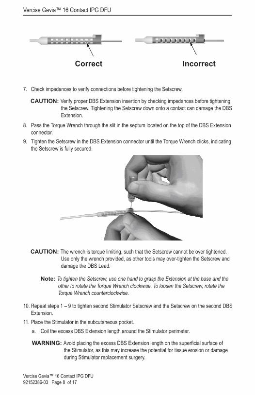
Vercise Gevia™ 16 Contact IPG DFU
Vercise Gevia™ 16 Contact IPG DFU 92152386-03 Page 8 of 17
Correct Incorrect
7. Check impedances to verify connections before tightening the Setscrew.
CAUTION: Verify proper DBS Extension insertion by checking impedances before tightening the Setscrew. Tightening the Setscrew down onto a contact can damage the DBS Extension.
8. Pass the Torque Wrench through the slit in the septum located on the top of the DBS Extension connector.
9. Tighten the Setscrew in the DBS Extension connector until the Torque Wrench clicks, indicating the Setscrew is fully secured.
CAUTION: The wrench is torque limiting, such that the Setscrew cannot be over tightened. Use only the wrench provided, as other tools may over-tighten the Setscrew and damage the DBS Lead.
Note: To tighten the Setscrew, use one hand to grasp the Extension at the base and the other to rotate the Torque Wrench clockwise. To loosen the Setscrew, rotate the Torque Wrench counterclockwise.
10. Repeat steps 1 – 9 to tighten second Stimulator Setscrew and the Setscrew on the second DBS Extension.
11. Place the Stimulator in the subcutaneous pocket. a. Coil the excess DBS Extension length around the Stimulator perimeter.
WARNING: Avoid placing the excess DBS Extension length on the superficial surface of the Stimulator, as this may increase the potential for tissue erosion or damage during Stimulator replacement surgery.

Vercise Gevia System Revisions and Explantation
Vercise Gevia™ 16 Contact IPG DFU 92152386-03 Page 9 of 17
b. Optionally secure the Stimulator to the fascia by suturing through the holes in the Stimulator header.
12. Close the incisions.
CAUTION: Be careful not to damage the DBS Lead, Stimulator, or other implanted components when closing the incisions.
Note: When closing the incision over the extension connector, orient the extension connector to minimize the profile under the skin.
Vercise Gevia System Revisions and ExplantationIf the entire Vercise Gevia System (Stimulator, DBS Extensions, and DBS Leads) is to be removed, then the DBS Leads should be removed first (as described below) followed by the DBS Extensions, and lastly the Stimulator. This order will reduce the potential spread of infection toward the skull opening.
Explanting the DBS LeadWARNING: When explanting the Vercise Gevia DBS System, the DBS Lead should be
pulled from the site above the ear and not the site near the burr hole to avoid a potential spread of infection toward the skull opening.
1. Turn off the Stimulator.2. Palpate the scalp to locate the Burr Hole Cover (BHC).3. Make an incision near the BHC to expose the BHC and DBS Lead. Be careful not to damage or
cut the DBS Lead or suture sleeve.4. Cut the DBS Lead at a distance about 2-3 cm from the BHC, leaving enough length to grasp
the Lead.5. Unscrew the screws anchoring the BHC. 6. Slowly and gently retract the DBS Lead from the neural tissue, pulling as close to perpendicular
to the skull as possible. The DBS Lead should experience minimal resistance when retracted.7. Palpate the region under the scalp to locate the DBS Extension connector.8. Create an incision to expose the DBS Lead and DBS Extension connector. Be careful not to
damage the implanted components to allow for proper analysis following explant.9. Loosen the connector Setscrew on the DBS Extension using the Torque Wrench provided.
Note: Be sure to fully insert the Torque Wrench before loosening the Setscrew. To tighten the Setscrew, rotate the Torque Wrench clockwise. To loosen the Setscrew, rotate the Torque Wrench counterclockwise.
10. Remove the DBS Lead from the DBS Extension.11. Gently pull the remainder of the DBS Lead through the incision behind the ear.
WARNING: The DBS Lead should be pulled from the site behind the ear and not the site near the burr hole to avoid a potential spread of infection toward the skull opening.

Vercise Gevia™ 16 Contact IPG DFU
Vercise Gevia™ 16 Contact IPG DFU 92152386-03 Page 10 of 17
12. If you are replacing the DBS Lead, follow the instructions in the appropriate lead manual as listed on your DBS Reference Guide. If you are explanting the entire Vercise Gevia System, continue on to the Explanting the DBS Extensions procedure. Otherwise, close the incisions.
13. Ship the explanted DBS Leads to Boston Scientific.
Explanting the DBS Extensions1. Turn off the Stimulator.2. Palpate the region under the scalp to locate the DBS Extension connector.3. Create an incision to expose the DBS Lead and DBS Extension connector. Be careful not to
damage the implanted components to allow for proper analysis following explant.4. Cut the DBS Extension(s) at the tapered (proximal) end of the connector. 5. Loosen the connector Setscrew using the Torque Wrench provided.
CAUTION: Loosen the Setscrew only as much as necessary to remove the DBS Lead. Loosening the Setscrew too much will cause it to fall out.
Note: To tighten the Setscrew, rotate the Torque Wrench clockwise. To loosen the Setscrew, rotate the Torque Wrench counterclockwise.
6. Disconnect the DBS Extension connector. Return the DBS Extension connector to Boston Scientific.
7. Expose and disconnect the DBS Extensions from the Stimulator by following the procedure in “Explanting or Replacing the Stimulator.”
8. Gently pull the DBS Extension through the tunnel from the Stimulator site.
WARNING: Avoid pulling towards the ear to reduce the potential for infection of the DBS Leads.
9. Ship the explanted DBS Extensions to Boston Scientific.
Note: If the DBS Extension has broken, then it may be necessary to make additional incisions or to pull one end of the DBS Extension out at the Stimulator site and the other end from the DBS Extension connector site.
Explanting or Replacing the Stimulator1. Turn off the Stimulator.2. Palpate the subclavicular area to locate the Stimulator.3. Surgically open the pocket where the Stimulator is located. Be careful not to damage the
implanted components to allow for proper analysis following explant.
CAUTION: Do not use electrocautery as it will damage the Stimulator.
Note: The incision should be large enough to remove the Stimulator from the pocket.
4. Withdraw the Stimulator from the pocket.

The Vercise Gevia Stimulator
Vercise Gevia™ 16 Contact IPG DFU 92152386-03 Page 11 of 17
5. Using the Torque Wrench, unscrew the header Setscrews to release the DBS Extensions.
CAUTION: Loosen the Setscrew only as much as necessary to remove the DBS Extension. Loosening the Setscrew too much will cause it to fall out.
Note: To tighten the Setscrew, rotate the Torque Wrench clockwise. To loosen the Setscrew, rotate the Torque Wrench counterclockwise.
6. Remove the DBS Extensions from the Stimulator. 7. If the Stimulator is to be replaced, reconnect the new Stimulator by following the procedures in
“Connecting the Stimulator”.8. If the DBS Extensions will remain implanted, you may optionally clean the proximal ends of the
DBS Extensions, attach Lead Boots, and coil the excess DBS Extension material in the pocket. 9. Close the incision.10. Ship the explanted Stimulator to Boston Scientific.
CAUTION: Be careful not to damage any remaining implanted components when closing the incision.
The Vercise Gevia StimulatorThe Vercise Gevia Stimulator is rechargeable. Boston Scientific recommends any recharge routine that fits the patient’s schedule and lifestyle while maintaining sufficient charge to maintain stimulation. Developing a patient’s recharge routine involves finding the right balance among the following:
• How much power is required for the patient to experience effective therapy• How often the patient wants to recharge• How long the patient wants to recharge• How the patient would like to manage their personal schedule
The patient Remote Control displays the Stimulator battery status when communicating with the Stimulator. When the Remote Control indicates a low battery the Stimulator should be recharged as soon as possible. Failure to recharge may lead to loss of stimulation in less than 24 hours. After stimulation stops, communication with the Stimulator will also cease until a sufficient level of charge has been attained.For instructions on charging the Stimulator, refer to the Charging the Stimulator section in this manual. For instructions on checking Stimulator Battery status refer to the appropriate Remote Control DFU for the Vercise Gevia DBS System as listed on your DBS Reference Guide.The Clinician Programmer (CP) will estimate charging time based on 24 hours per day of stimulation at the programmed settings. Refer to the Programming Manual for the Vercise Gevia DBS System as listed in your DBS Reference Guide.

Vercise Gevia™ 16 Contact IPG DFU
Vercise Gevia™ 16 Contact IPG DFU 92152386-03 Page 12 of 17
Charging the StimulatorThe Charger Base Station should be plugged in and the Charger placed in the Base Station when not in use. When the indicator light is green, the Charger is fully charged. When the indicator is amber, the Charger is partially charged, but is still able to deliver a charge to the Stimulator.1. When the indicator light is green, remove the Charger from the Base Station. The indicator light
will then turn off.2. Press the power button. The indicator light will come on again, and the Charger will begin
beeping as it searches for the Stimulator. 3. When charging the Stimulator, the patient must use the Charger with either the Charging Collar
or an Adhesive Patch to hold the Charger over the Stimulator. Using the Charging Collar
a. If the patient’s Stimulator is in a shallow location or if the patient has thin skin, instruct the patient to place the Charging Spacer at the back of the pocket in the Charging Collar. Patients with shallow Stimulators or thin skin will be able to charge faster with the Charging Spacer.
Note: Patients with Stimulators in a deep location should not use the Charging Spacer, as it may slow the speed of charging.
b. Place the Charger into the appropriate pocket on the Charging Collar with the power button facing out. If the Stimulator is on the right side of the chest, place the Charger in the right pocket. If the Stimulator is on the left side of the body, place the Charger in the left pocket.
c. If using the Charging Spacer, make sure it is between the Charger and the back of the pocket.
d. Place the Counterweight in the pocket opposite of the Charger.e. Place the Charging Collar over the neck with the pockets facing out.f. For best charging results, make sure the Charger is centered over the Stimulator. If the
Charger is not centered, charging time may increase. If the Charger is not centered over the Stimulator, the patient may need to adjust the length of the Charging Collar using the straps. Occasionally checking that the Charger is aligned over the Stimulator during the charging session is recommended. When the Charger is aligned with the Stimulator, the beeping will stop.
Note: The Charging Collar can be placed under or over clothing. The patient should not wear tight fitting or heavy clothing over the Charger while charging to allow air flow around the Charger.
Using the Adhesive Patch
Note: The Adhesive Patches are made of non-reactive and natural Latex-free material suitable for most sensitive skin types.
a. Apply the Adhesive Patch to the backside of the Charger by peeling the clear liner from the patch and applying the white side with the blue stripe to the rear of the Charger.
b. Remove the skin side beige liner from the adhesive (only good for one fixation).

The Vercise Gevia Stimulator
Vercise Gevia™ 16 Contact IPG DFU 92152386-03 Page 13 of 17
c. For best charging results, make sure the Charger is centered over the Stimulator. If the Charger is not centered, charging time may increase. When the Charger is aligned with the Stimulator, the beeping will stop.
WARNING: Do not put the Charger directly on the skin (e.g., without an Adhesive Patch). This may result in uncomfortable heating of the skin or a burn.
4. When the Charger emits a series of double beeps, the Stimulator is fully charged. Turn off the Charger and remove the collar or adhesive patch, and return the Charger to the Base Station.
Note: Do not confuse the end of charge signal (a series of double beeps) with the repeated beeps that indicate that the Charger is searching for the Stimulator.
Note: The Remote Control will not be able to communicate with the Stimulator when charging.
Physical Characteristics of the Vercise Gevia StimulatorThe physical characteristics of the Stimulator are outlined in Table 1. The Stimulator contains a radiopaque identification tag. The identification tag is visible using standard x-ray procedures.
Table 1: Stimulator Physical Properties
Feature Description
Case Titanium
Header Epoxy
Strain Relief Silicone
Dimensions 51.3 mm x 46.0 mm x 10.8 mm
Volume 19.8 cm3 (including header)
Stimulator Programmable CharacteristicsThe stimulation parameters are independent for the two DBS Leads such that stimulation of two different brain targets can have different amplitudes, pulse widths, stimulation rates, and contact configurations. The two DBS Leads can also have differing monopolar and multipolar configurations. The programmable parameter ranges for the Stimulator are shown in Table 2.

Vercise Gevia™ 16 Contact IPG DFU
Vercise Gevia™ 16 Contact IPG DFU 92152386-03 Page 14 of 17
Note: Some frequency combinations may not be used. Refer to the Programming Manual for more information on programming multiple frequencies.
Table 2: Stimulator Function
Parameter Range
Waveform Charge balanced, asymmetric biphasic
Pulse Shape Rectangular
Current or Voltage Regulated Current
Amplitude1 0.1 – 20 mA
Rate2 2 – 255 Hz
Pulse Width 20 – 450 µs
Cycle (On/Off) 1 s – 90 min
Stim Ramp On 1 – 10 s
Contact Connections 16
Independent Areas of Stim (4 Programs with 4 Areas per Program) 16
Current Path Options Unipolar, Bipolar, or Multipolar
1 The programmable coverage for each individual contact is limited to 12.7 mA. A programming interlock is enforced to limit the total output current to 20 mA or less per coverage area. For example, a maximum current output of 12.7 mA on one contact would limit the total summed current output on the remaining contacts to 7.3 mA within one coverage area.2 The rate is limited to a sum of 255 Hz for a given port. The global rate limit for each lead is also 255 Hz.

DBS Extension
Vercise Gevia™ 16 Contact IPG DFU 92152386-03 Page 15 of 17
Stimulation Output at Maximum Parameters vs. Impedance. The above graphs show the maximum output current when stimulation settings are set to the maximum values on a Ring or Directional electrode (Amplitude Max = 12.7 mA, PW = Various shown (450, 240, 120, 30 µs), Rate Max = 255 Hz). Please note that for typical parameters (PW=60 µs, Rate=130 Hz, Amplitude=3 mA), these limits are not expected to be reached.
DBS ExtensionThe DBS Extension consists of a connector at the distal end and 8 cylindrical contacts at the proximal end. The DBS Lead may be inserted and secured into the connector, which also contains 8 contacts that align with the contacts on the DBS Lead to form electrical connections. The DBS Extension can be implanted and attached to the Stimulator and the DBS Lead for bilateral stimulation.
Table 3: DBS Extension
Feature Description
Overall Length 55 cm
Outer Diameter 1.35 mm
Number of Contacts 8
Contact Material Platinum/Iridium
Insulation Material Polyurethane, Silicone
Vercise Gevia™ 16 Contact IPG DFU
Vercise Gevia™ 16 Contact IPG DFU 92152386-03 Page 16 of 17
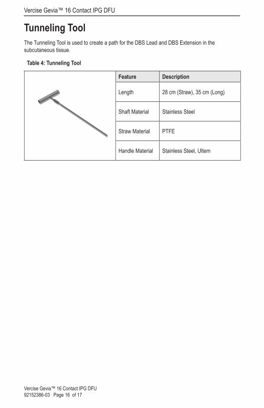
Tunneling Tool The Tunneling Tool is used to create a path for the DBS Lead and DBS Extension in the subcutaneous tissue.
Table 4: Tunneling Tool
Feature Description
Length 28 cm (Straw), 35 cm (Long)
Shaft Material Stainless Steel
Straw Material PTFE
Handle Material Stainless Steel, Ultem

Tunneling Tool
Vercise Gevia™ 16 Contact IPG DFU 92152386-03 Page 17 of 17
This page intentionally left blank.

© 2018 Boston Scientific Corporation or its affiliates. All rights reserved.
92152386-03 2018-07
Legal Manufacturer AUSAustralian Sponsor Address EC REP EU Authorized
RepresentativeBoston Scientific Neuromodulation Corporation25155 Rye Canyon LoopValencia, CA 91355 USA(866) 789-5899 in US and Canada(661) 949-4000, (661) 949-4022 Fax(866) 789-6364 TTYwww.bostonscientific.comEmail: [email protected]
Boston Scientific (Australia) Pty LtdPO Box 332BOTANYNSW 1455AustraliaFree Phone 1800 676 133Free Fax 1800 836 666
Boston Scientific LimitedBallybrit Business ParkGalway, IrelandT: +33 (0) 1 39 30 97 00F: +33 (0) 1 39 30 97 99