verilog module introduction and combinationalusers.wpi.edu/~rjduck/verilog module introduction and...
TRANSCRIPT
Jim Duckworth, WPI Module 11
Verilog – Module 1
Introduction and Combinational Logic
Jim Duckworth
ECE Department, WPI
Jim Duckworth, WPI Verilog Module Rev B2
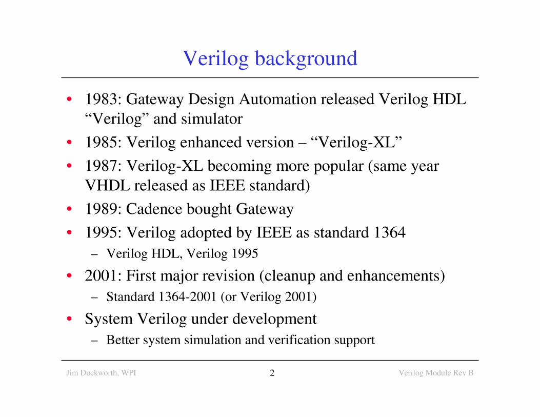
Verilog background
• 1983: Gateway Design Automation released Verilog HDL
“Verilog” and simulator
• 1985: Verilog enhanced version – “Verilog-XL”
• 1987: Verilog-XL becoming more popular (same year
VHDL released as IEEE standard)
• 1989: Cadence bought Gateway
• 1995: Verilog adopted by IEEE as standard 1364
– Verilog HDL, Verilog 1995
• 2001: First major revision (cleanup and enhancements)
– Standard 1364-2001 (or Verilog 2001)
• System Verilog under development
– Better system simulation and verification support
Jim Duckworth, WPI Verilog Module Rev B3
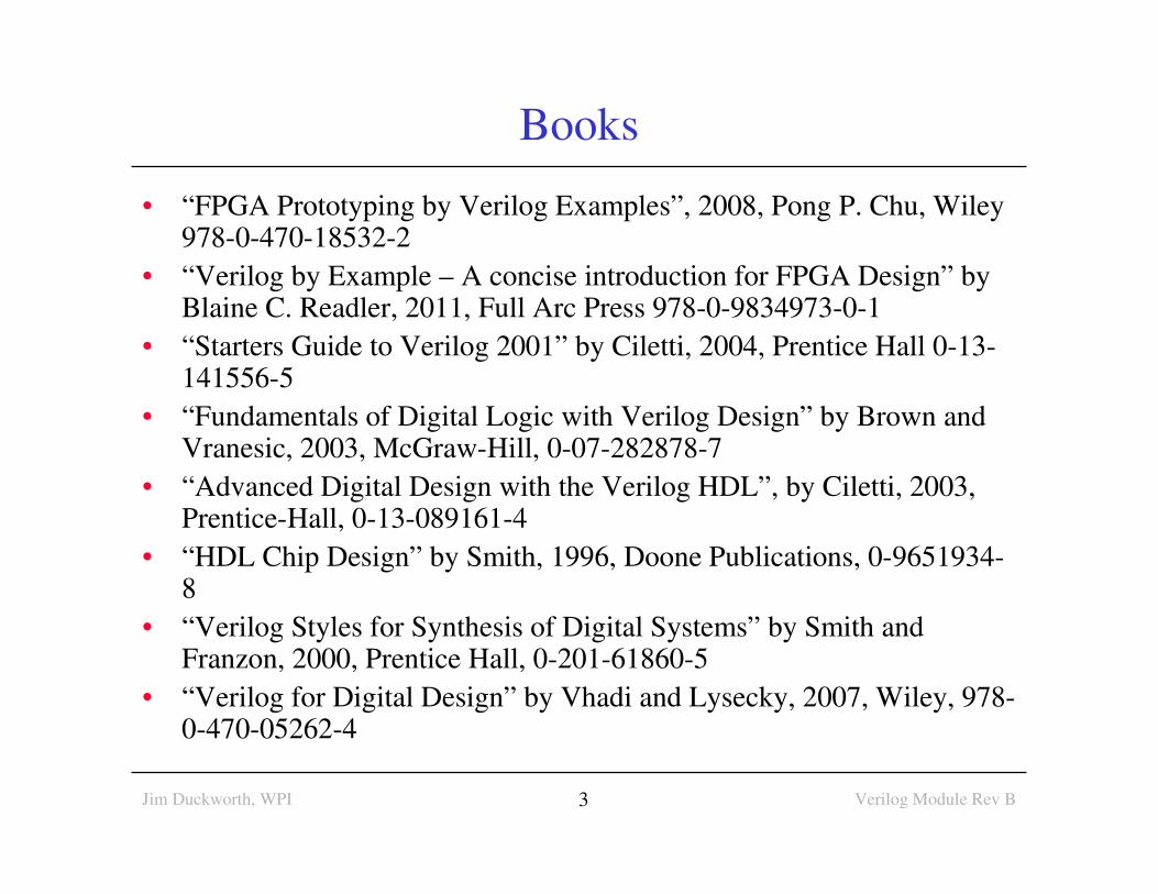
Books
• “FPGA Prototyping by Verilog Examples”, 2008, Pong P. Chu, Wiley 978-0-470-18532-2
• “Verilog by Example – A concise introduction for FPGA Design” by Blaine C. Readler, 2011, Full Arc Press 978-0-9834973-0-1
• “Starters Guide to Verilog 2001” by Ciletti, 2004, Prentice Hall 0-13-141556-5
• “Fundamentals of Digital Logic with Verilog Design” by Brown and Vranesic, 2003, McGraw-Hill, 0-07-282878-7
• “Advanced Digital Design with the Verilog HDL”, by Ciletti, 2003, Prentice-Hall, 0-13-089161-4
• “HDL Chip Design” by Smith, 1996, Doone Publications, 0-9651934-8
• “Verilog Styles for Synthesis of Digital Systems” by Smith and Franzon, 2000, Prentice Hall, 0-201-61860-5
• “Verilog for Digital Design” by Vhadi and Lysecky, 2007, Wiley, 978-0-470-05262-4
Jim Duckworth, WPI Verilog Module Rev B4
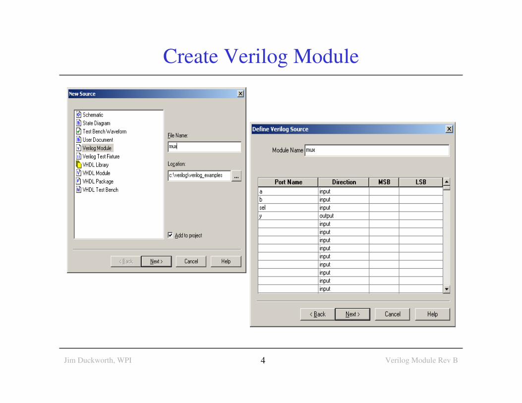
Create Verilog Module
Jim Duckworth, WPI Verilog Module Rev B5
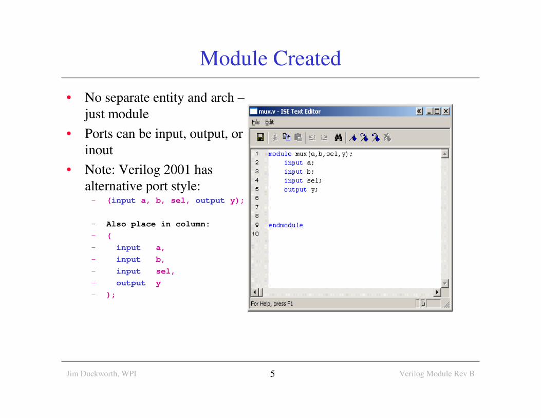
Module Created
• No separate entity and arch –
just module
• Ports can be input, output, or
inout
• Note: Verilog 2001 has
alternative port style:– (input a, b, sel, output y);
– Also place in column:
– (
– input a,
– input b,
– input sel,
– output y
– );
Jim Duckworth, WPI Verilog Module Rev B6
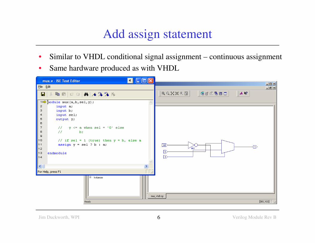
Add assign statement
• Similar to VHDL conditional signal assignment – continuous assignment
• Same hardware produced as with VHDL
Jim Duckworth, WPI Verilog Module Rev B7
Verilog - general comments
• VHDL is like ADA and Pascal in style
• Strongly typed – more robust than Verilog
• In Verilog it is easier to make mistakes
• Watch for signals of different widths
• No default required for case statement, etc
• Verilog is more like the ‘c’ language
• Verilog IS case sensitive
• White space is OK
• Statements terminated with semicolon (;)
• Verilog statements between
• module and endmodule
• Comments // single line and /* and */
Jim Duckworth, WPI Module 18
Verilog and VHDL – Reminder
• VHDL - like Pascal and Ada programming languages
• Verilog - more like ‘C’ programming language
• But remember they are Hardware Description Languages -
They are NOT programming languages
– FPGAs do NOT contain an hidden microprocessor or interpreter or
memory that executes the VHDL or Verilog code
– Synthesis tools prepare a hardware design that is inferred from the
behavior described by the HDL
– A bit stream is transferred to the programmable device to configure
the device
– No shortcuts! Need to understand combinational/sequential logic
• Uses subset of language for synthesis
• Check - could you design circuit from description?
Jim Duckworth, WPI Verilog Module Rev A9
Verilog – Combinational Logic
Verilog for Synthesis
Jim Duckworth, WPI Verilog Module Rev A10
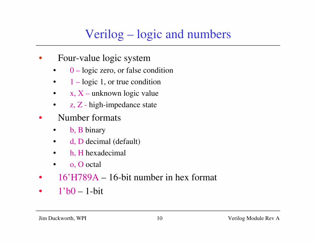
Verilog – logic and numbers
• Four-value logic system
• 0 – logic zero, or false condition
• 1 – logic 1, or true condition
• x, X – unknown logic value
• z, Z - high-impedance state
• Number formats
• b, B binary
• d, D decimal (default)
• h, H hexadecimal
• o, O octal
• 16’H789A – 16-bit number in hex format
• 1’b0 – 1-bit

Jim Duckworth, WPI Verilog Module Rev A11
Verilog types
• Constants– parameter DIME = 10;
– parameter width = 32, nickel = 5;
– parameter quarter = 8’b0010_0101;
• Nets– wire clock, reset_n;
– wire[7:0] a_bus;
• Registers– reg clock, reset_n;
– reg[7:0] a_bus;
• Integer
– only for use as general purpose variables in loops
– integer n;
Jim Duckworth, WPI Verilog Module Rev A12
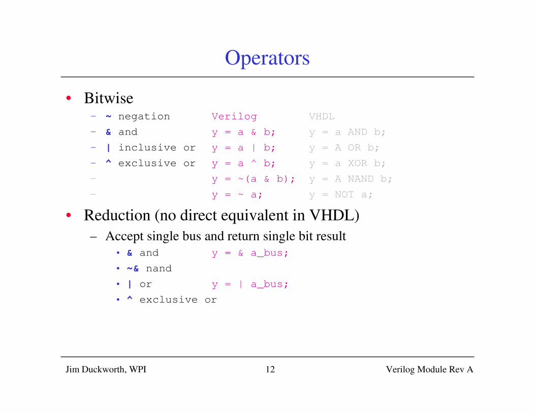
Operators
• Bitwise– ~ negation Verilog VHDL
– & and y = a & b; y = a AND b;
– | inclusive or y = a | b; y = A OR b;
– ^ exclusive or y = a ^ b; y = a XOR b;
– y = ~(a & b); y = A NAND b;
– y = ~ a; y = NOT a;
• Reduction (no direct equivalent in VHDL)
– Accept single bus and return single bit result
• & and y = & a_bus;
• ~& nand
• | or y = | a_bus;
• ^ exclusive or
Jim Duckworth, WPI Verilog Module Rev A13
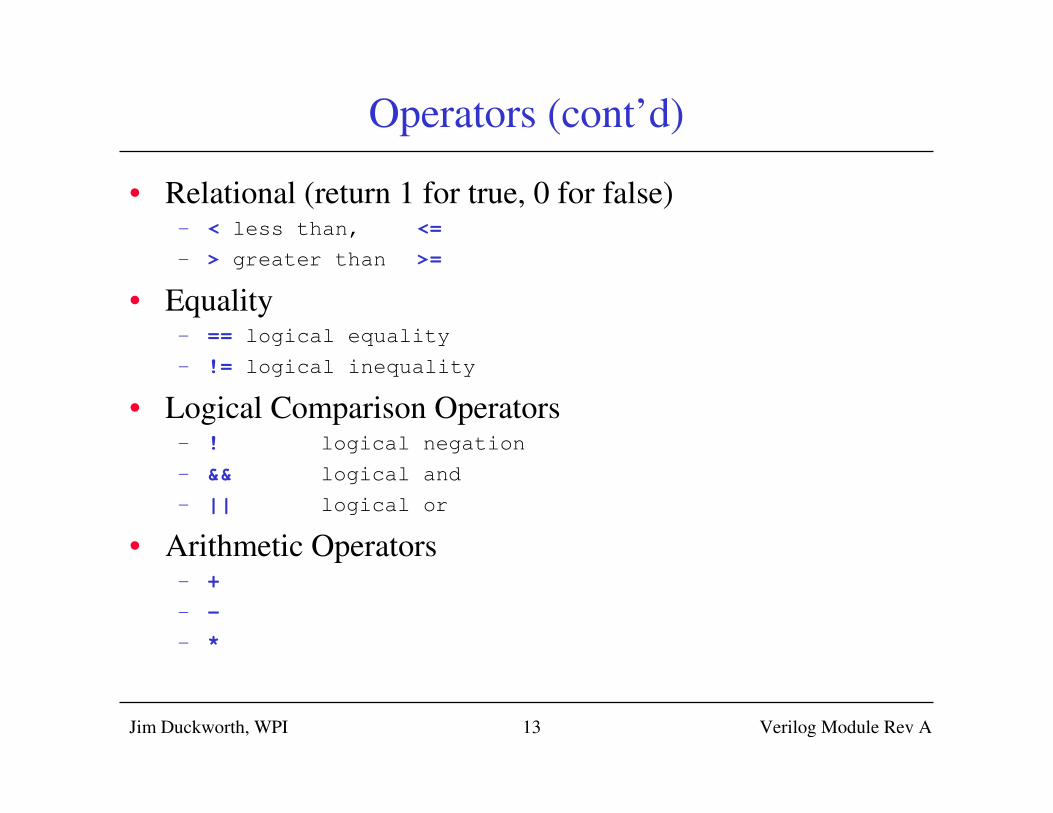
Operators (cont’d)
• Relational (return 1 for true, 0 for false)– < less than, <=
– > greater than >=
• Equality– == logical equality
– != logical inequality
• Logical Comparison Operators– ! logical negation
– && logical and
– || logical or
• Arithmetic Operators– +
– -
– *
Jim Duckworth, WPI Verilog Module Rev A14
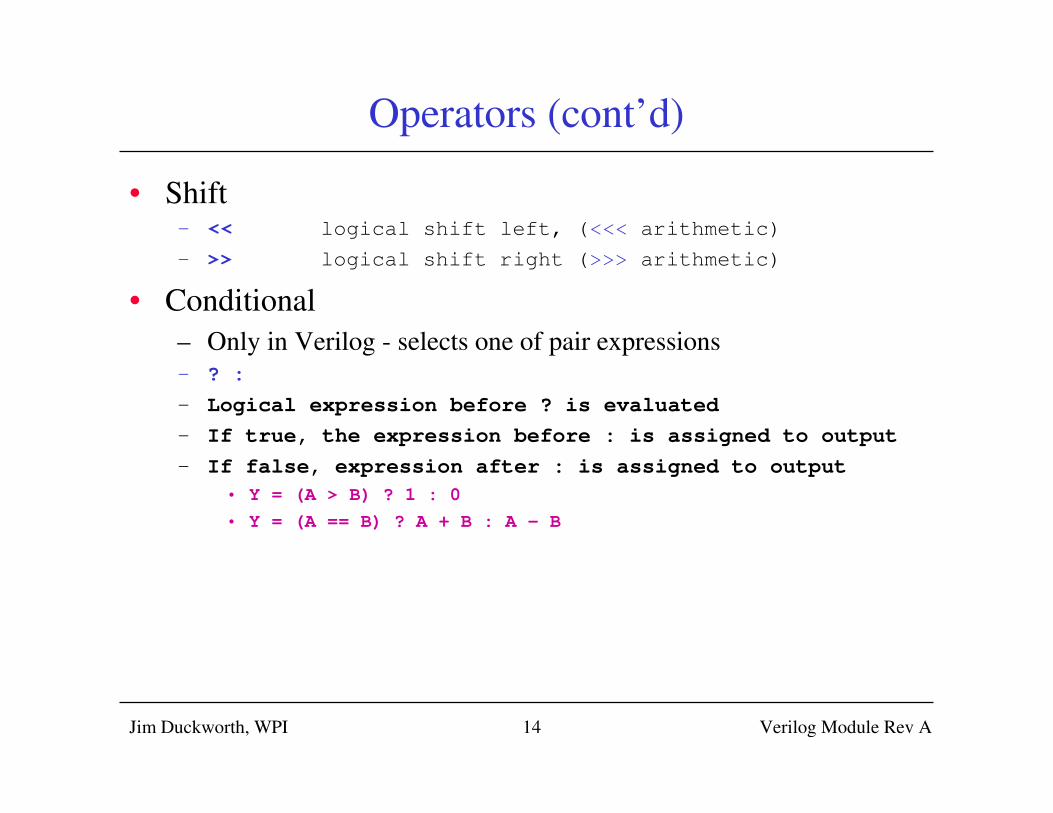
Operators (cont’d)
• Shift– << logical shift left, (<<< arithmetic)
– >> logical shift right (>>> arithmetic)
• Conditional
– Only in Verilog - selects one of pair expressions
– ? :
– Logical expression before ? is evaluated
– If true, the expression before : is assigned to output
– If false, expression after : is assigned to output
• Y = (A > B) ? 1 : 0
• Y = (A == B) ? A + B : A – B
Jim Duckworth, WPI Verilog Module Rev A15
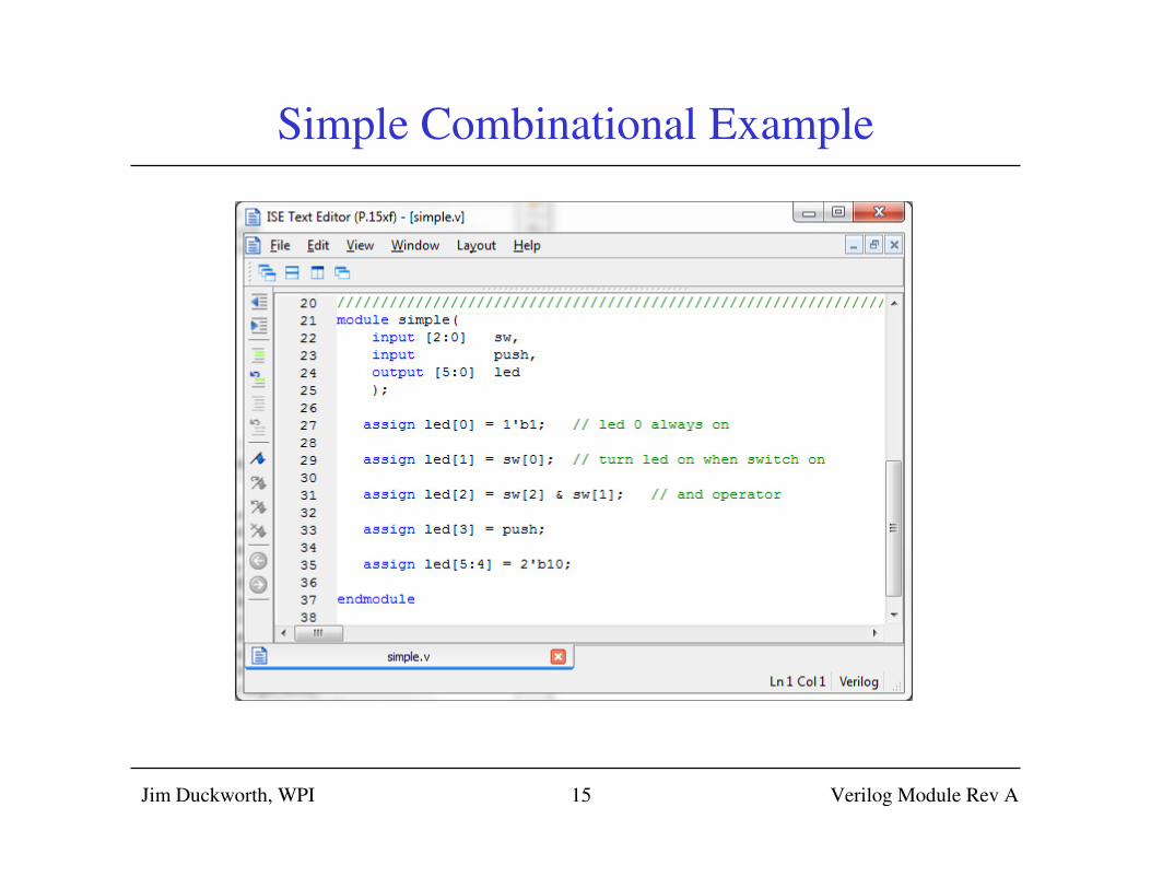
Simple Combinational Example
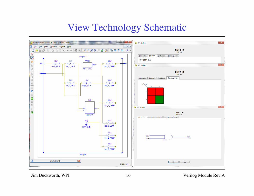
View Technology Schematic
Jim Duckworth, WPI Verilog Module Rev A16
Jim Duckworth, WPI Module 117
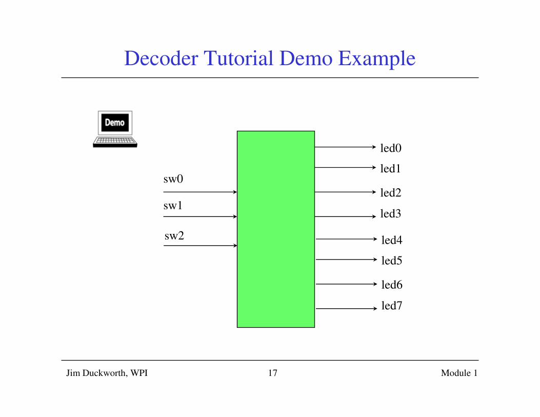
Decoder Tutorial Demo Example
sw0
sw1
led0
led1
led2
led3
led4
led5
led6
led7
sw2
Jim Duckworth, WPI Module 118
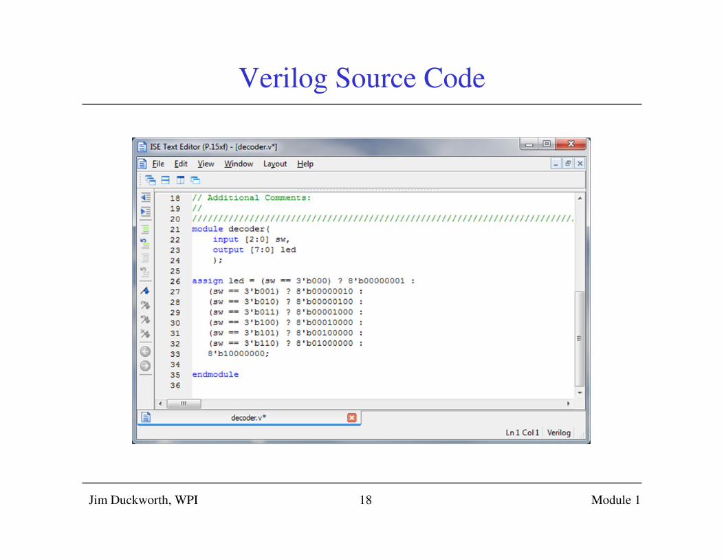
Verilog Source Code
Jim Duckworth, WPI Verilog Module Rev A19
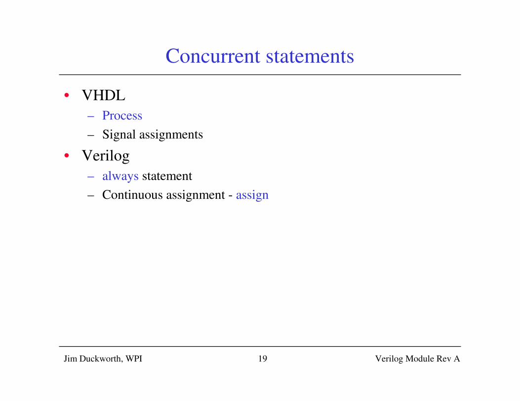
Concurrent statements
• VHDL
– Process
– Signal assignments
• Verilog
– always statement
– Continuous assignment - assign
Jim Duckworth, WPI Verilog Module Rev A20
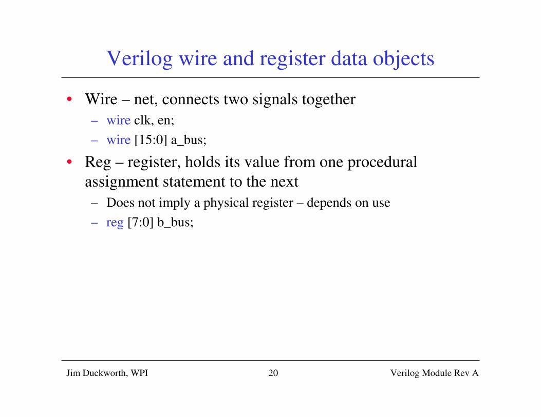
Verilog wire and register data objects
• Wire – net, connects two signals together
– wire clk, en;
– wire [15:0] a_bus;
• Reg – register, holds its value from one procedural
assignment statement to the next
– Does not imply a physical register – depends on use
– reg [7:0] b_bus;
Jim Duckworth, WPI Verilog Module Rev A21
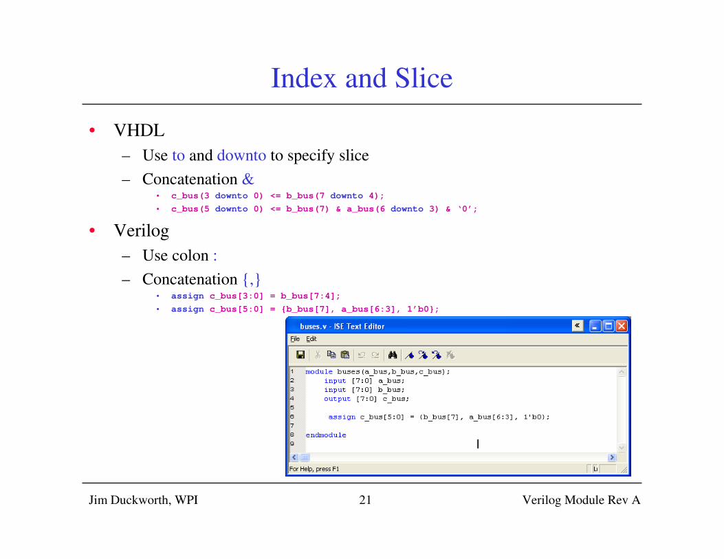
Index and Slice
• VHDL
– Use to and downto to specify slice
– Concatenation &• c_bus(3 downto 0) <= b_bus(7 downto 4);
• c_bus(5 downto 0) <= b_bus(7) & a_bus(6 downto 3) & ‘0’;
• Verilog
– Use colon :
– Concatenation {,}• assign c_bus[3:0] = b_bus[7:4];
• assign c_bus[5:0] = {b_bus[7], a_bus[6:3], 1’b0};

Jim Duckworth, WPI Verilog Module Rev A22
Internal wires
• Declare internal wires:

Jim Duckworth, WPI Verilog Module Rev A23
Sequential Statements
• VHDL
– reside in process statement
• Verilog
– reside in an always statement
– if statements (no endif)
– case statements (endcase)
– for, repeat while loop statements
– Note: use begin and end to block sequential statements
Jim Duckworth, WPI Verilog Module Rev A24
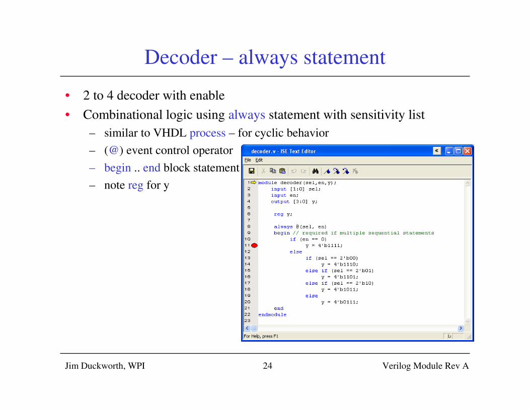
Decoder – always statement
• 2 to 4 decoder with enable
• Combinational logic using always statement with sensitivity list
– similar to VHDL process – for cyclic behavior
– (@) event control operator
– begin .. end block statement
– note reg for y
Jim Duckworth, WPI Verilog Module Rev A25
Decoder (cont’d)
• Combinational logic using always statement with
sensitivity list
– similar to VHDL process – for cyclic behavior
– (@) event control operator
– begin .. end block statement
• Statements execute sequentially
– if statement
– case statement
• Note: case expression can concatenate signals ({,})
– Sensitivity list
• (a or b or c)
• Verilog 2001 allows comma-separated list (a, b, c)
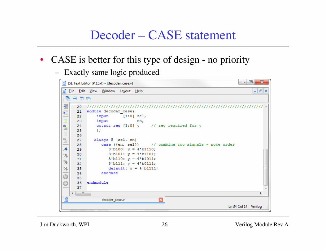
Decoder – CASE statement
• CASE is better for this type of design - no priority
– Exactly same logic produced
Jim Duckworth, WPI Verilog Module Rev A26
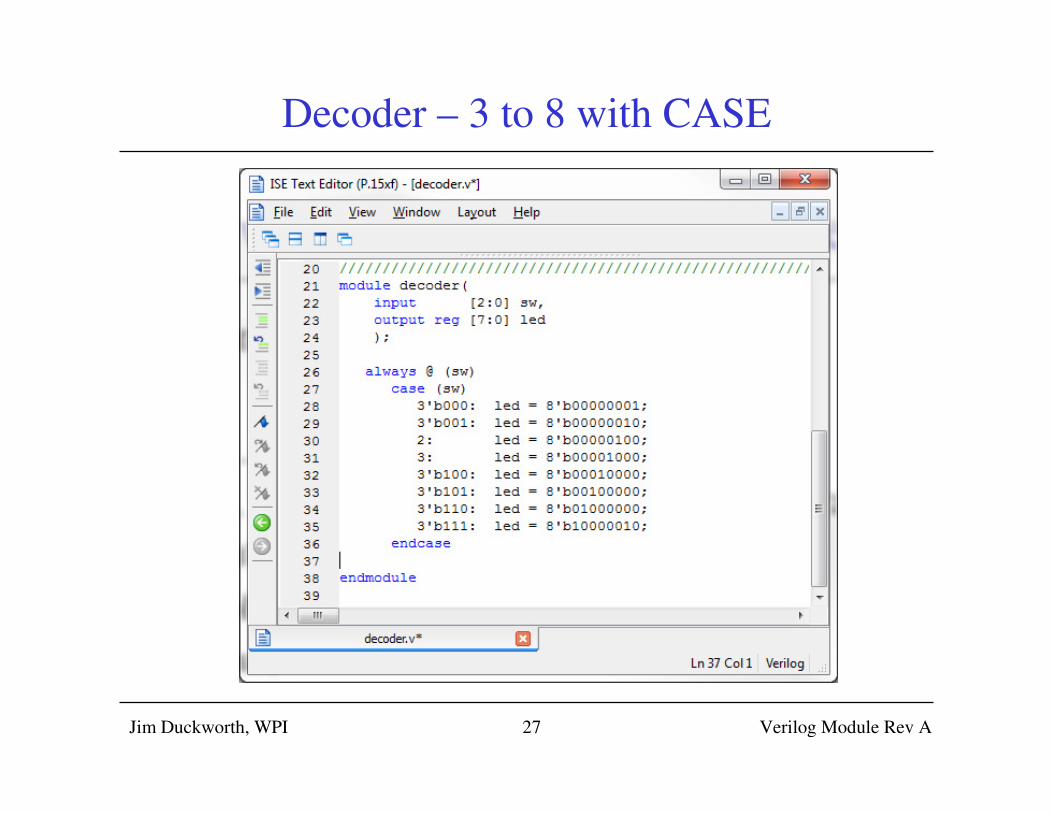
Decoder – 3 to 8 with CASE
Jim Duckworth, WPI Verilog Module Rev A27
Jim Duckworth, WPI Verilog Module Rev A28
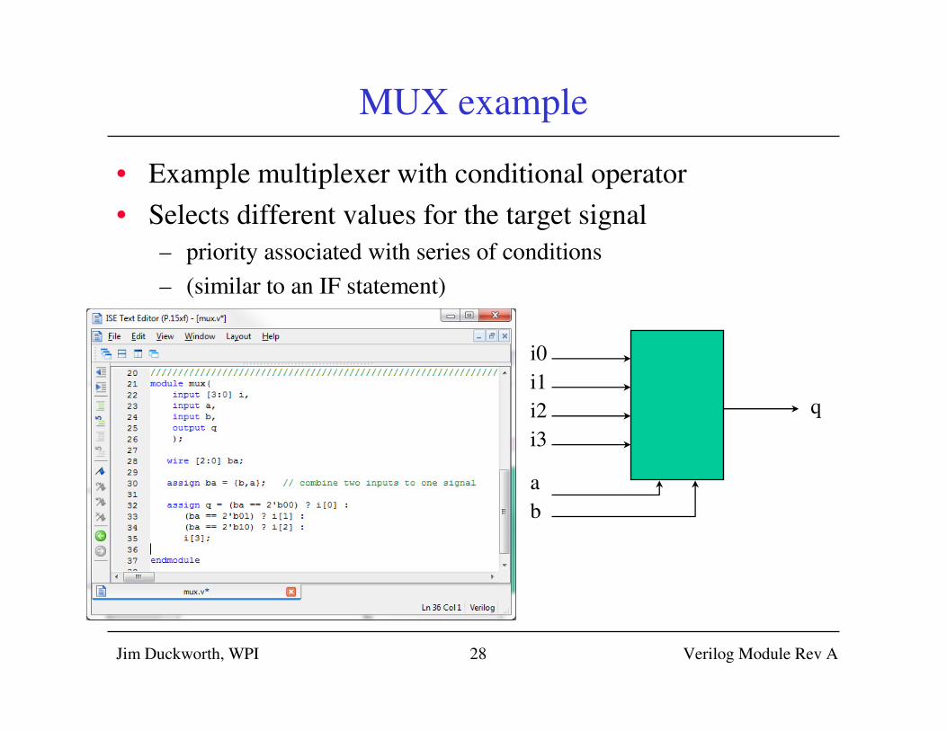
MUX example
• Example multiplexer with conditional operator
• Selects different values for the target signal
– priority associated with series of conditions
– (similar to an IF statement)
i0
q
i1
i2
i3
a
b
Jim Duckworth, WPI Verilog Module Rev A29
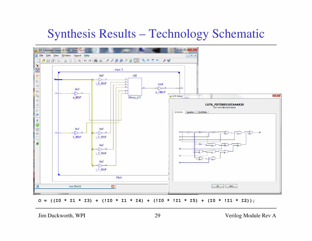
Synthesis Results – Technology Schematic
O = ((I0 * I1 * I3) + (!I0 * I1 * I4) + (!I0 * !I1 * I5) + (I0 * !I1 * I2));
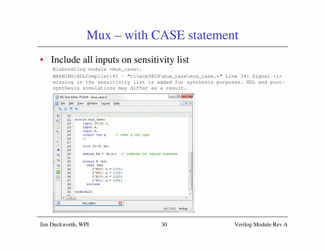
Mux – with CASE statement
• Include all inputs on sensitivity listElaborating module <mux_case>.
WARNING:HDLCompiler:91 - "C:\ece3829\mux_case\mux_case.v" Line 34: Signal <i>
missing in the sensitivity list is added for synthesis purposes. HDL and post-
synthesis simulations may differ as a result.
Jim Duckworth, WPI Verilog Module Rev A30
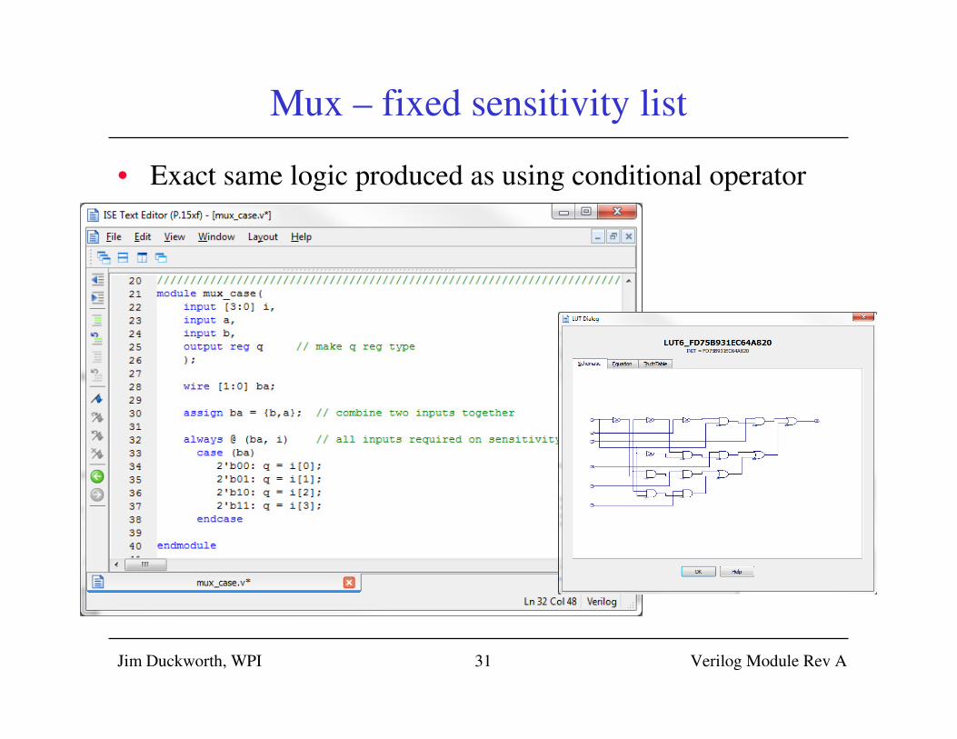
Mux – fixed sensitivity list
• Exact same logic produced as using conditional operator
Jim Duckworth, WPI Verilog Module Rev A31
Jim Duckworth, WPI Verilog Module Rev A32
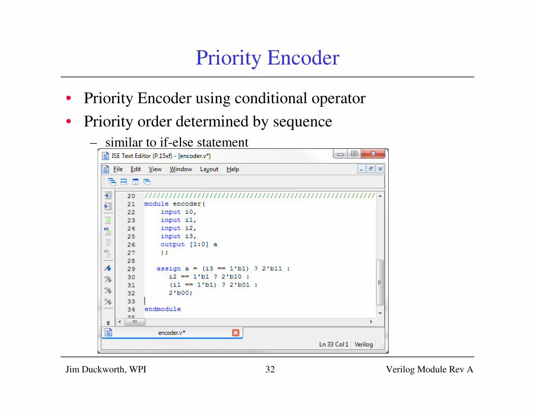
Priority Encoder
• Priority Encoder using conditional operator
• Priority order determined by sequence
– similar to if-else statement
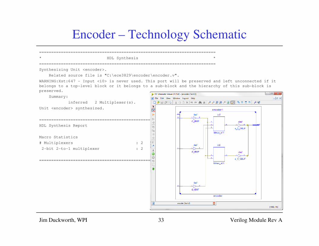
Encoder – Technology Schematic
=========================================================================
* HDL Synthesis *
=========================================================================
Synthesizing Unit <encoder>.
Related source file is "C:\ece3829\encoder\encoder.v".
WARNING:Xst:647 - Input <i0> is never used. This port will be preserved and left unconnected if it
belongs to a top-level block or it belongs to a sub-block and the hierarchy of this sub-block is
preserved.
Summary:
inferred 2 Multiplexer(s).
Unit <encoder> synthesized.
===============================================================
HDL Synthesis Report
Macro Statistics
# Multiplexers : 2
2-bit 2-to-1 multiplexer : 2
===============================================================
Jim Duckworth, WPI Verilog Module Rev A33
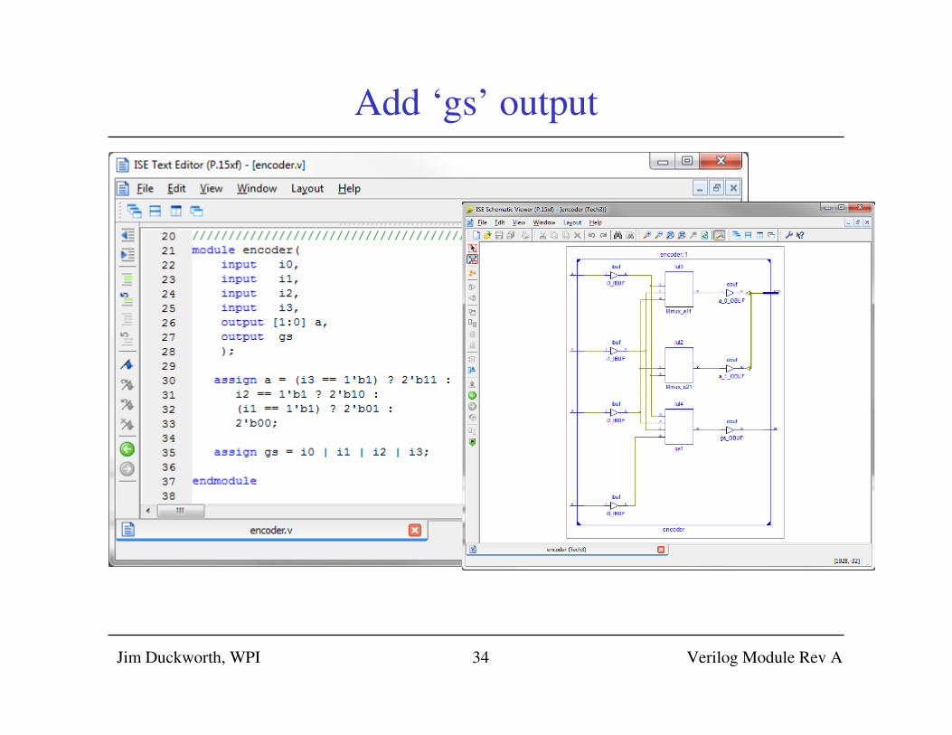
Add ‘gs’ output
Jim Duckworth, WPI Verilog Module Rev A34
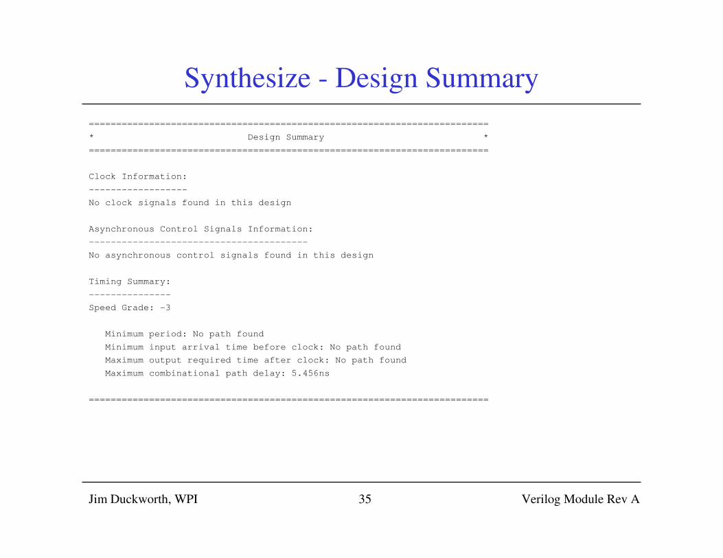
Synthesize - Design Summary
=========================================================================
* Design Summary *
=========================================================================
Clock Information:
------------------
No clock signals found in this design
Asynchronous Control Signals Information:
----------------------------------------
No asynchronous control signals found in this design
Timing Summary:
---------------
Speed Grade: -3
Minimum period: No path found
Minimum input arrival time before clock: No path found
Maximum output required time after clock: No path found
Maximum combinational path delay: 5.456ns
=========================================================================
Jim Duckworth, WPI Verilog Module Rev A35
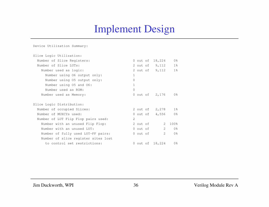
Implement Design
Device Utilization Summary:
Slice Logic Utilization:
Number of Slice Registers: 0 out of 18,224 0%
Number of Slice LUTs: 2 out of 9,112 1%
Number used as logic: 2 out of 9,112 1%
Number using O6 output only: 1
Number using O5 output only: 0
Number using O5 and O6: 1
Number used as ROM: 0
Number used as Memory: 0 out of 2,176 0%
Slice Logic Distribution:
Number of occupied Slices: 2 out of 2,278 1%
Number of MUXCYs used: 0 out of 4,556 0%
Number of LUT Flip Flop pairs used: 2
Number with an unused Flip Flop: 2 out of 2 100%
Number with an unused LUT: 0 out of 2 0%
Number of fully used LUT-FF pairs: 0 out of 2 0%
Number of slice register sites lost
to control set restrictions: 0 out of 18,224 0%
Jim Duckworth, WPI Verilog Module Rev A36
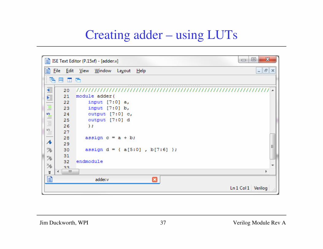
Creating adder – using LUTs
Jim Duckworth, WPI Verilog Module Rev A37
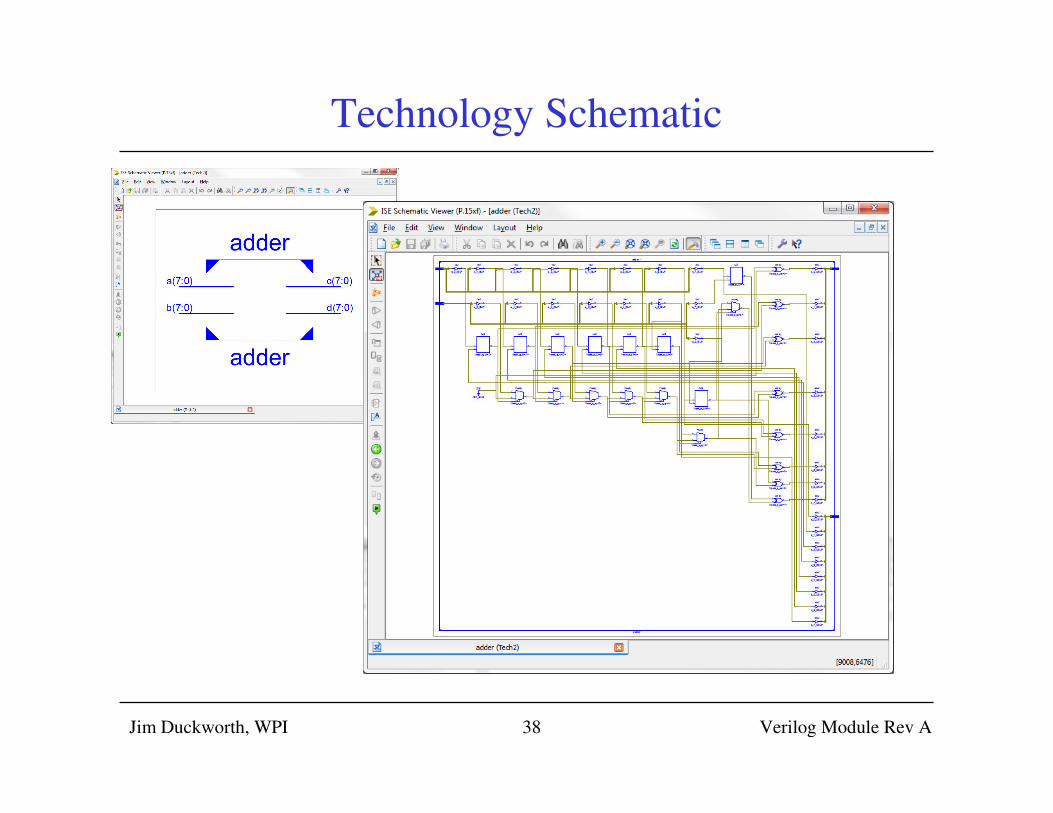
Technology Schematic
Jim Duckworth, WPI Verilog Module Rev A38
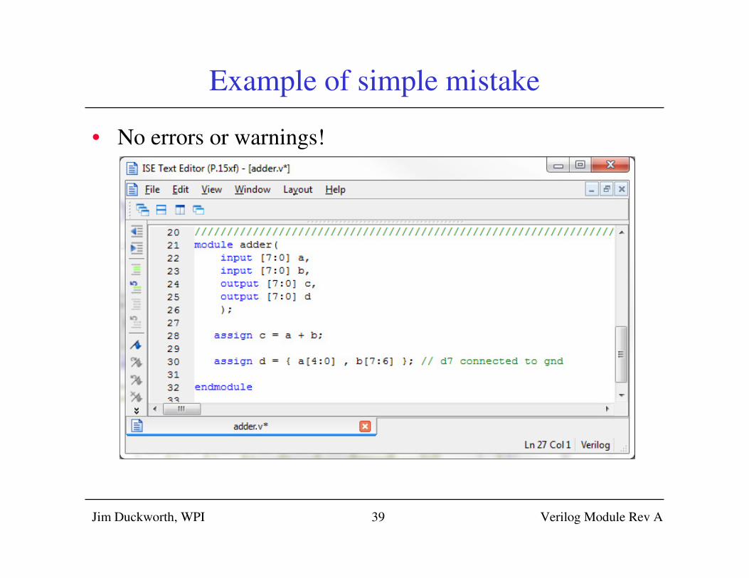
Example of simple mistake
• No errors or warnings!
Jim Duckworth, WPI Verilog Module Rev A39
Jim Duckworth, WPI Verilog Module Rev A40
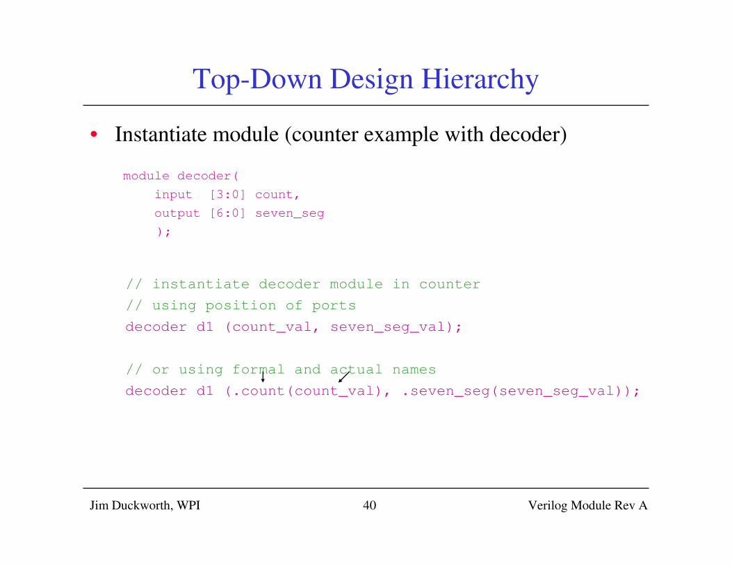
Top-Down Design Hierarchy
• Instantiate module (counter example with decoder)
module decoder(
input [3:0] count,
output [6:0] seven_seg
);
// instantiate decoder module in counter
// using position of ports
decoder d1 (count_val, seven_seg_val);
// or using formal and actual names
decoder d1 (.count(count_val), .seven_seg(seven_seg_val));
Jim Duckworth, WPI Verilog Module Rev A41
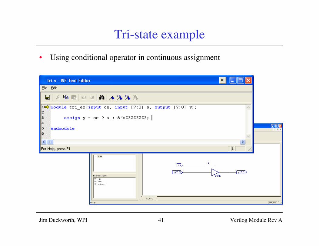
Tri-state example
• Using conditional operator in continuous assignment