vero-s modular system for manual workpiece direct clamping
TRANSCRIPT

Translation of Original Operating Manual
Superior Clamping and Gripping 01.00|WDM 80 |de
VERO-S Modular system for manual Workpiece direct clamping WDM-5X
Assembly and Operating Manual

Imprint
01.00|WDM 80 |en 2
Imprint Copyright: This manual is protected by copyright. The author is SCHUNK GmbH & Co. KG. All rights reserved. Any reproduction, processing, distribution (making available to third parties), translation or other usage – even excerpts – of the manual is especially prohibited and requires our written approval. Technical changes: We reserve the right to make technical improvements. Document number: 1404624 Version: 01.00 |28.05.2019|de © H.-D. SCHUNK GmbH & Co. All rights reserved Dear Customer,
Thank you for putting your trust in our products and our family-owned company, the leading technology supplier of robots and production machines.
Our team is always available to answer any questions concerning this product or other solutions. We look forward to your challenging questions. We will find a solution!
Best regards, Your SCHUNK team H.-D. SCHUNK GmbH & Co. Spanntechnik KG
Lothringer Str. 23 D-88512 Mengen
Tel. +49–7572-7614-0 Fax +49-7572-7614-1099 [email protected] schunk.com

Table of Contents
01.00|WDM 80 |en 3
Table of Contents
1 General 5
1.1 About this Manual 5
1.1.1 Illustration of warning signs 5
1.1.2 Applicable documents 6
1.2 Warranty 6
1.3 Scope of Delivery 6
1.4 Accessories 7
2 Basic safety instructions 8
2.1 Appropriate use 8
2.2 Inappropriate use 8
2.3 Structural changes 8
2.4 Spare parts 9
2.5 Ambient conditions and operating conditions 9
2.6 Personnel qualification 9
2.7 Personal protective equipment 10
2.8 Note on safe operation 11
2.9 Transport 12
2.10 Malfunctions 12
2.11 Disposal 12
2.12 Fundamental dangers 13
2.12.1 Protection during handling and assembly 13
2.12.2 Protection during commissioning and operation 13
2.12.3 Protection against dangerous movements 14
2.12.4 Notes on particular risks 14
3 Technical data 16
4 Screw tightening torques 17

Table of Contents
01.00|WDM 80 |en 4
5 Assembly 17
5.1 Pre-assembly measures 17
5.2 General Installation Notes 18
5.3 Clamping pins SPA 40, SPB 40, SPC 40, SPG 40 18
5.3.1 Standard clamping pins 19
5.3.2 Clamping pins without collar 21
5.3.3 Clamping pins with position balancing SPD-B, SPD-C 22
6 Functional description 23
6.1 WDM-5X basic module 23
6.1.1 WDM-5X-BM 80-75 and WDM-5X-BM 80-100 23
6.1.2 WDM-5X-BM 80-125, WDM-5X-BM 80-150, WDM-5X-BM 80-175 24
6.1.3 WDM-5X-BDM 80-125 24
6.2 WDM-5X Basic heigh extension 25
6.3 WDM-5X Add-on module 26
6.3.1 WDM-5X-SM 80-75 26
6.3.2 WDM-5X-SDM 80-125 (double clamping module) 27
6.4 WDM-5X Reduction adapter 28
6.4.1 Reduction adapter SBA-VL 28
6.4.2 Height-adjustable adapter SBA-HE 29
6.4.3 Plane grip adapter SBA-VLK 30
6.4.4 Collet chuck adapter SBA-SEZ 30
7 Operation 31
8 Maintenance and care 32
9 Troubleshooting 33
10 Parts lists 34
10.1 Basic modules 34
10.2 Height extension for basic module 36
10.3 Add-on modules 36
10.4 Reduction adapter 37
11 Assembly drawings 39
General
01.00|WDM 80 |en 5
1 General
1.1 About this Manual
This manual contains important information for the safe, correct use of the product.
The manual is an integral part of the product and must be kept accessible by personnel at all times.
Personnel must have read and understood this manual before beginning any work. The observance of all safety notes in this manual is the precondition for all safe working.
The illustrations in this manual are intended to provide a basic understanding and may deviate from the actual version. Besides this manual, other documents which apply are those listed under
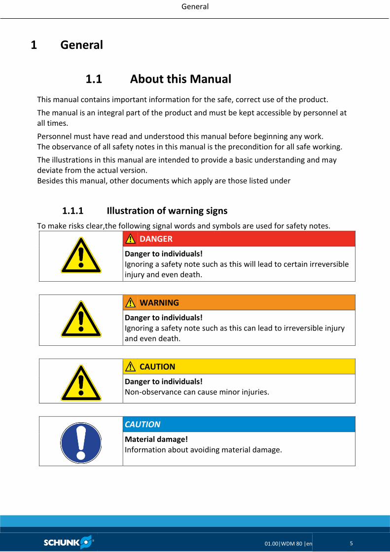
1.1.1 Illustration of warning signs
To make risks clear,the following signal words and symbols are used for safety notes.
DANGER
Danger to individuals! Ignoring a safety note such as this will lead to certain irreversible injury and even death.
WARNING
Danger to individuals! Ignoring a safety note such as this can lead to irreversible injury and even death.
CAUTION
Danger to individuals! Non-observance can cause minor injuries.
CAUTION
Material damage! Information about avoiding material damage.

General
01.00|WDM 80 |en 6
1.1.2 Applicable documents
• General terms and conditions *
• Catalog data sheet for purchased product *
The documents labeled with an asterisk (*) can be downloaded from schunk.com.
1.2 Warranty
The warranty is valid for:
• 24 months from delivery date from the production facility or
• 50,000 cycles for VERO-S clamping systems WDM -5X for use as intended under the following conditions:
• Observance of the applicable documents
• Observance of the ambient conditions and operating conditions
• Observance of the specified care and maintenance instructions
Parts touching the workpiece and wearing parts are not part of the warranty.
* One cycle comprises one complete clamping procedure (“opening” and “closing”).
1.3 Scope of Delivery
• Direct workpiece clamping module o Basic module WDM-5X_BM 80-75 o Basic module WDM-5X_BM 80-100 o Basic module WDM-5X_BM 80-125 o Basic module WDM-5X_BM 80-150 o Basic module WDM-5X_BM 80-175 o Basic module WDM-5X_BDM 80-125 o Basic height extension WDM-5X—BP 235-235-50 o Basic height extension WDM-5X—BP 270-250-36 o Stacking module WDM-5X-SM 80-75 o Stacking module WDM-5X-SM 80-100 o Stacking module WDM-5X-SM 80-125 o Stacking module WDM-5X-SDM 80-125 o Reduction adapter SBA-VL-P 50-M16 o Reduction adapter SBA-VL-PA 50-M16 o Reduction adapter SBA-VL 25-M12 o Height-adjustable adapter SBA-HE 50-75 o Plane grip adapter SBA-VLK 75-M10 o Collet chuck adapter SBA-SEZ ER50-100

General
01.00|WDM 80 |en 7
• Assembly and Operating Manual (ID no. 1404624)
• Accessory pack o WDM-5X_BM 80-75: 2 mounting screws M12 x 35 o WDM-5X_BM 80-100: 2 mounting screws M12 x 35 o WDM-5X_BM 80-125: 2 mounting screws M12 x 45 o WDM-5X_BM 80-150: 2 mounting screws M12 x 45 o WDM-5X_BM 80-175: 2 mounting screws M12 x 45 o WDM-5X_BDM 80-125: 2 mounting screws M12 x 45 o WDM-5X—BP 235-235-50: (without accessory kit) o WDM-5X—BP 270-250-36: (without accessory kit) o WDM-5X-SM 80-75: (without accessory kit) o WDM-5X-SM 80-100: (without accessory kit) o WDM-5X-SM 80-125: (without accessory kit) o WDM-5X-SDM 80-125: (without accessory kit) o SBA-VL-P 50-M16: (without accessory kit) o SBA-VL-PA 50-M16: (without accessory kit) o SBA-VL 25-M12: 1 clamping pin SBA 16, 1 mounting screw M12 x 75 o SBA-VL 50-M12: 1 clamping pin SBA 16, 1 mounting screw M12 x 100 o SBA-HE 50-75: 1 clamping pin SBA 20 o SBA-VLK 75-M10: (without accessory kit) o SBA-SEZ ER50-100: clamping pin SBA 20
1.4 Accessories
(see catalog or data sheets when ordering separately) Clamping pin type SBA 40, SBB 40, SBC 40 swing bolt PDSC M16 fitting screw PSC Ø12 and PSC Ø16 clamping pin type SPA 40, SPB 40, SPC 40, SPG 40 positioning arbor Allen wrench torque wrench

Basic safety instructions
01.00|WDM 80 |en 8
2 Basic safety instructions
2.1 Appropriate use
The clamping systems VERO-S WDB 80 are intended for clamping workpieces and devices on machine tools and other suitable technical devices. This is implemented via modular components that can be combined for workpiece direct clamping, taking into account the defined technical data.
• The clamping systems may only be used on the basis of their technical data.
• The clamping systems are intended for industrial applications.
• Appropriate use of the product includes compliance with all instructions in this manual.
2.2 Inappropriate use
The VERO-S WDM 80 clamping system is not being used as intended if, for example:
• it is used as a pressing tool, a toolholder, a load-handling device or as lifting equipment.
• It is used for turning applications without consulting SCHUNK.
• It is used in working environments that are not permissible.
• People work on machines or technical equipment that do not comply with the EC Machinery Directive 2006/42/EC, disregarding the applicable safety regulations.
• The technical data specified by the manufacturer are exceeded during usage.
2.3 Structural changes
Implementation of structural changes Modifications, changes or reworking, e.g. additional threads, holes, or safety devices due to conversions, could damage the product or impair its functionality or safety.
• Structural changes should only be made with the written approval of SCHUNK.

Basic safety instructions
01.00|WDM 80 |en 9
2.4 Spare parts
Use of unauthorized spare parts Using unauthorized spare parts can endanger personnel and damage the product or cause it to malfunction.
• Use only original spare parts or spares authorized by SCHUNK.
2.5 Ambient conditions and operating conditions
Required ambient conditions and operating conditions Incorrect ambient and operating conditions can make the product unsafe, leading to the risk of serious injuries, considerable material damage and/or a significant reduction to the product's life span.
• Make sure that the product is only used within its defined application parameters.
• Make sure that the product is a sufficient size for the application.
• Make sure that the contact surfaces of the interface are always clean. Make absolutely sure that no chips of any kind can enter the interface and that the interface does not fill with cooling emulsion, which is particularly possible with vertical alignment of the clamping pin axis. The best way to ensure both of these requirements is to use the SDE protection covers. If the interface should fill with cooling emulsion, the interface can be dried out in opened state.
• Only use high-quality cooling emulsions with anti-corrosive additives during processing.
2.6 Personnel qualification
Work on the product by inadequately qualified personnel can lead to serious injuries and considerable material damage.
• Order all work to be performed only by appropriately qualified personnel.
• Personnel must have read and understood the complete manual before beginning any work on the product.
• Observe national accident prevention regulations and the general safety notes.

Basic safety instructions
01.00|WDM 80 |en 10
The following personnel qualifications are required for the various types of work on the product: Qualified electrician: Electricians have professional training, knowledge, and experience that equip them to work on electrical systems, recognize and avoid potential dangers, and they know the relevant standards and regulations. Specialist personnel: Specialist personnel have the specialized training, knowledge, and experience to perform the tasks entrusted to them, to recognize and avoid potential dangers, and know the relevant standards and instructions. Instructed person: Instructed persons have been instructed by the user regarding the tasks entrusted to them and the potential dangers of inappropriate behavior. Manufacturer's service personnel: The manufacturer's service personnel have the specialized training, knowledge, and experience to perform the work entrusted to them and to recognize and avoid potential dangers.
2.7 Personal protective equipment
Use of personal protective equipment Personal protective equipment serves to protect staff against danger which may interfere with their health or safety at work.
• When working on and with the product, observe the occupational health and safety regulations and wear the required personal protective equipment.
• Observe the valid safety and accident prevention regulations.
• Wear protective gloves to guard against sharp edges and corners or rough surfaces.
• Wear heat-resistant protective gloves when handling hot surfaces.
• Wear protective gloves and safety goggles when handling hazardous substances.
• Wear close-fitting protective clothing and also wear long hair in a hairnet when dealing with moving components.

Basic safety instructions
01.00|WDM 80 |en 11
2.8 Note on safe operation
Incorrect manner of working by personnel Working in an incorrect manner can make the product unsafe and risk the danger of serious injuries and considerable material damages.
• Avoid any manner of working that may interfere with the function and operational safety of the product.
• Use the product as intended.
• Observe the safety notes and assembly instructions.
• Do not expose the product to any corrosive media. Products for special ambient conditions are excluded.
• Rectify malfunctions as soon as they occur.
• Observe the care and maintenance instructions.
• Observe the current safety, accident prevention, and environmental protection regulations for the application field of the product.
Maintenance instructions Observe the care and maintenance instructions. These instructions are based on a normal working environment. If the product is to be operated in an environment with abrasive dusts or corrosive or aggressive fumes or fluids, prior approval must be obtained from SCHUNK. Safety during assembly and maintenance During assembly, connection, adjustment, start-up and testing, make sure that no accidental operation of the system by the fitter or other persons is possible.
Holding force and screw strength
The holding force of the system is limited essentially by the tightness of the screw connection which connects the clamping pin to the pallet or the device. This is why only screws of strength class 12.9 may be used.
Only original SCHUNK clamping pins may be used.
If the clamping pins are to be used in customer-owned devices, the customer must provide sufficiently dimensioned threaded holes or a sufficiently thick mounting material.

Basic safety instructions
01.00|WDM 80 |en 12
2.9 Transport
Handling during transport
Incorrect handling during transport can make the product unsafe and risk serious injuries and considerable material damage.
• When handling heavy weights, use lifting equipment to lift the product and transport it by appropriate means.
• During transport and handling, secure the product to prevent it from falling.
• Do not walk under suspended loads.
2.10 Malfunctions
Behavior in case of malfunctions
• Immediately remove the product from operation and report the malfunction to the responsible departments/persons.
• Order appropriately trained personnel to rectify the malfunction.
• Do not recommission the product until the malfunction has been rectified.
• Test the product after a malfunction to establish whether it still functions properly and no increased risks have arisen.
2.11 Disposal
Handling of disposal Incorrect handling during disposal can make the product unsafe and risks serious injuries and considerable material and environmental harm.
• Follow local regulations on dispatching product components for recycling or orderly disposal.

Basic safety instructions
01.00|WDM 80 |en 13
2.12 Fundamental dangers
General
• Observe safety distances.
• Never deactivate safety devices.
• Before commissioning the product, take appropriate protective measures to secure the danger zone.
• Disconnect power sources before installation, modification, maintenance, or calibration. Ensure that no residual energy remains in the system.
• Do not reach into the open mechanism or movement area of the product during operation.
2.12.1 Protection during handling and assembly
Incorrect handling and assembly Incorrect handling and assembly can make the product unsafe and risk the danger of serious injuries and considerable material damage.
• Order all work to be performed only by appropriately qualified personnel.
• For all work, secure the product against accidental operation.
• Observe the relevant accident prevention regulations.
• Use suitable assembly and transport equipment and take precautions to prevent jamming and crushing.
Incorrect lifting of loads Falling loads can cause serious injuries and even death.
• Stand clear of suspended loads and do not step within their swiveling range.
• Never move loads without supervision.
• Do not leave suspended loads unattended.
2.12.2 Protection during commissioning and operation
Falling or violently ejected components Falling and violently ejected components can cause serious injuries and even death.
• Take appropriate protective measures to secure the danger zone.
• Never step into the danger zone during operation.

Basic safety instructions
01.00|WDM 80 |en 14
2.12.3 Protection against dangerous movements
Unexpected movements If the system still retains residual energy, serious injuries can be caused while working on the product.
• Perform maintenance work, modifications, and attachments outside the danger zone defined by the movement range.
• To avoid accidents and/or material damage, human access to the movement range of the machine must be restricted. Limit/prevent accidental access for people in this area through technical safety measures. The protective cover and protective fence must be rigid enough to withstand the maximum possible movement energy. EMERGENCY STOP switches must be easily and quickly accessible. Before commissioning the machine or automated system, check that the EMERGENCY STOP system is working. Prevent operation of the machine if this protective equipment does not function correctly.
2.12.4 Notes on particular risks
WARNING
Risk of injury due to falling parts when setting up, fitting and transporting the workpiece direct clamping module. Parts that have not been properly secured can come loose and fall down.
• Use suitable lifting equipment and means of transport.
• When fitting the clamping structure, do not enter the danger zone.
• Wear personal protective equipment.
WARNING
Risk of injury to the operating personnel when transporting the direct workpiece clamping module or if the clamping structure, the device or the workpiece falls.
• Use a crane or a transport truck when transporting.
• During horizontal or overhead applications, the device or pallet must be secured before loosening to prevent it from falling.

Basic safety instructions
01.00|WDM 80 |en 15
WARNING
Risk of injury due to falling device, pallet or workpiece if the clamping pin or the change interfaces on the workpiece direct clamping modules are loosened erroneously or as a result of negligence.
• During operation, any loosening of the clamping pin as a result of negligence must be excluded using appropriate counter measures.
• The machines and equipment must fulfill the minimum requirements of the EC Machinery Directive 2006/42/EC; specifically, they must have effective technical measures to protect against potential mechanical hazards.
• Wear personal protective equipment.
CAUTION
There is a risk of limbs being crushed by moving parts during manual loading and unloading and the clamping procedure.
• Do not reach into the clamping pin holder.
• Use loading devices.
• Wear protective gloves.

Technical data
01.00|WDM 80 |en 16
3 Technical data
Installation position Any
Operating temperature + 15°C – + 60°C
Required level of cleanliness in accordance with DIN EN 60529
IP 30
Characterization WDM-5X-BM 80-75
WDM-5X-BM 80-100
WDM-5X-BM 80-125
WDM-5X-BM 80-150
ID 1398160 1398161 1398162 1398163
Height 75 mm 100 mm 125 mm 150 mm
Holding force * 35 kN (M10) / 50 kN (M12) / 75 kN (M16)
Pull-in force 25 kN
Actuation torque 15 Nm
Weight 3.55 kg 4.45 kg 6.65 kg 7.60 kg
Characterization WDM-5X-BM 80-175
WDM-5X-BDM 80-125
WDM-5X-SM 80-75
WDM-5X-SM 80-100
ID 1398164 1398171 1398181 1398182
Height 175 mm 125 mm 75 mm 100 mm
Holding force * 35 kN (M10) / 50 kN (M12) / 75 kN (M16)
Pull-in force 25 kN
Actuation torque 15 Nm
Weight 8.45 kg 5.00 kg 2.85 kg 3.65 kg
Characterization WDM-5X-SM 80-125
WDM-5X-SDM 80-125
ID 1398183 1398184
Height 125 mm 125 mm
Holding force * 35 kN (M10) / 50 kN (M12) / 75 kN (M16)
Pull-in force 25 kN
Actuation torque 15 Nm
Weight 4.70 kg 4.50 kg
* Holding force when fastening the clamping pin with cylindrical screw – DIN EN ISO 4762/12.9

Assembly
01.00|WDM 80 |de 17
4 Screw tightening torques
Screw tightening torques for mounting the base module WDM-5X-80-BM 80 onto the machine table (screw quality 10.9)
Screw size M10 M12 M16
Tightening torques MA (Nm) 52 92 224
5 Assembly
5.1 Pre-assembly measures
CAUTION
Risk of injury due to sharp edges and rough or slippery surfaces.
• Wear personal protective equipment, particularly protective gloves.
Check that the delivery is complete and that there is no transport damage. Assembly, dismantling and modification work on the workpiece direct clamping module may only be carried out by specialist personnel. Disconnect the power supply lines and ensure that there is no residual energy in the system before performing assembly, modification, maintenance, or adjustment work. Until the workpiece direct clamping module is assembled, access to the side attachment screw of the clamping units must be ensured, particularly when the clamping pallets are clamped. Before installing, check whether the drive pistons and the attachment screw can be easily reached for opening and for clamping and loosening the interface connection on the workpiece direct clamping systems respectively.
WARNING
Risk of injury due to falling when transporting the workpiece direct clamping module.
• Transport with care.
Assembly
01.00|WDM 80 |de 18
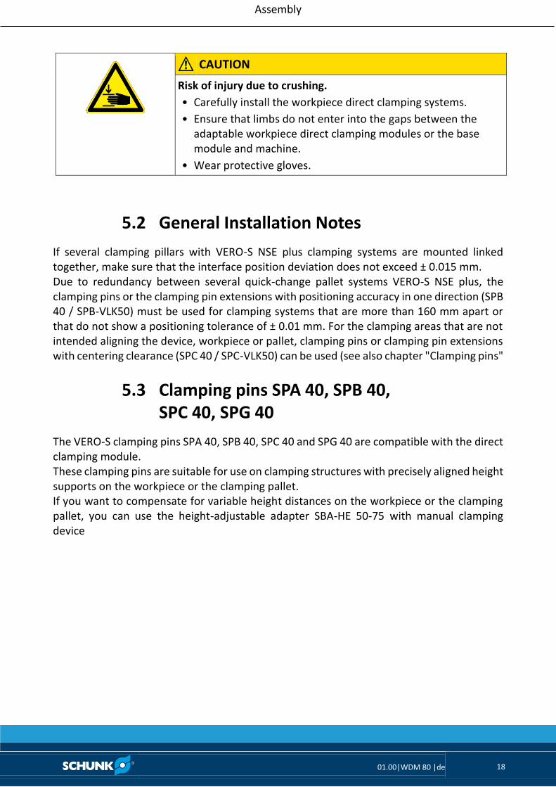
CAUTION
Risk of injury due to crushing.
• Carefully install the workpiece direct clamping systems.
• Ensure that limbs do not enter into the gaps between the adaptable workpiece direct clamping modules or the base module and machine.
• Wear protective gloves.
5.2 General Installation Notes
If several clamping pillars with VERO-S NSE plus clamping systems are mounted linked together, make sure that the interface position deviation does not exceed ± 0.015 mm. Due to redundancy between several quick-change pallet systems VERO-S NSE plus, the clamping pins or the clamping pin extensions with positioning accuracy in one direction (SPB 40 / SPB-VLK50) must be used for clamping systems that are more than 160 mm apart or that do not show a positioning tolerance of ± 0.01 mm. For the clamping areas that are not intended aligning the device, workpiece or pallet, clamping pins or clamping pin extensions with centering clearance (SPC 40 / SPC-VLK50) can be used (see also chapter "Clamping pins"
5.3 Clamping pins SPA 40, SPB 40, SPC 40, SPG 40
The VERO-S clamping pins SPA 40, SPB 40, SPC 40 and SPG 40 are compatible with the direct clamping module. These clamping pins are suitable for use on clamping structures with precisely aligned height supports on the workpiece or the clamping pallet. If you want to compensate for variable height distances on the workpiece or the clamping pallet, you can use the height-adjustable adapter SBA-HE 50-75 with manual clamping device

Assembly
01.00|WDM 80 |de 19
CAUTION
Notes on clamping pins and mounting screws The holding force of the quick-change pallet system is limited essentially by the tightness of the screw connection which connects the clamping pin to the pallet or the device.
• This is why only screws of strength class 12.9 may be used.
• Only original SCHUNK clamping pins may be used.
• If the clamping pins are to be used in customer-owned devices, the customer must provide sufficiently dimensioned threaded holes or a sufficiently thick mounting material.
5.3.1 Standard clamping pins
The clamping pins can be attached to the workpiece or pallet in two different ways; the mounting variants are however numbered in the preferred order.
Clamping pin installation
Screw Customer-specific pallet or device
Stee
l
Alu
min
um
Stee
l
Alu
min
um
Screw

Assembly
01.00|WDM 80 |de 20
Tolerances and installation conditions
Type ID A B C D E F G* H
SPA 40 RF 0471151 > 12 > 17 M12 > 15 > 20 M10 15 > 12
SPB 40 RF 0471152 > 12 > 17 M12 > 15 > 20 M10 15 > 12
SPC 40 RF 0471153 > 12 > 17 M12 > 15 > 20 M10 15 > 12
SPG 40 RF 0471154 > 12 > 17 M12 > 15 > 20 M10 25 > 22
SPA 40-16 RF 0471064 > 13 > 18 M16 > 18 > 24 M12 20 > 16
SPB 40-16 RF 0471065 > 13 > 18 M16 > 18 > 24 M12 20 > 16
SPC 40-16 RF 0471066 > 13 > 18 M16 > 18 > 24 M12 20 > 16
* The length of the screwed thread must not exceed the dimension “G” under any circumstances!
Usage/arrangement of the different types of clamping pins (Application: pallet with 6 clamping positions)
Tightening torques for mounting VERO-S clamping pins type SPA / SPB / SPC (Screw quality 12.9)
Screw size M10 M12 M14 M16
Tightening torque (Nm) 62 108 170 262
± 0.015 for type C ± 0.015 for type B
Type A clamping pin with positioning accuracy Type C clamping pin with centering clearance of 0.1 mm
± 0
.01
5 f
or
Typ
e C
cla
mp
ing
pin
±
0.0
15
fo
r Ty
pe
B c
lam
pin
g p
in
Type B clamping pin for positioning in one direction

Assembly
01.00|WDM 80 |de 21
5.3.2 Clamping pins without collar
The clamping pins without collar only require a slim fitting bore Ø 12 H7 or Ø 16 H7 in the installation space. For the SPC-OB design, no fit seating is required.
Clamping pin installation SPA 40-OB
Due to the shortened thread reach, reduced machining forces are intended for these clamping pins. The functionality and the selection for installation are described in chapter “Clamping pins SBA 40, SBB 40, SBC 40”.
Type ID
SBA-OB 40-12G6 1398355
SBB-OB 40-12G6 1398356
SBC-OB 40-12G6 1398357
SBA-OB 40-16G6 1398359
SBB-OB 40-16G6 1398360
SBC-OB 40-16G6 1398361
Customer-specific pallet or device
Fittin
g
leng
th

Assembly
01.00|WDM 80 |de 22
5.3.3 Clamping pins with position balancing SPD-B, SPD-C
The clamping pins have a movable clamping element which can be used to compensate for flexible bore hole fluctuations. The clamping pin SPA-X performs the function of a sword bolt and allows a position balancing in the longitudinal direction of ± 1 mm. For this use, a fit seating in the installation space is required. The clamping pin SPA-XY can be used to compensate for concentric positioning tolerances. These clamping pins can be combined with all other VERO-S clamping pins in a workpiece interface. Using these clamping pins ensures smooth operation of workpiece clamping.
Type ID
SPA-X 0471155
SPA-XY 0471156
Fittin
g
leng
th
Screw
Stee
l
Alu
min
um
Screw
Stee
l
Alu
min
um
Customer-specific pallet or device
Functional description
01.00|WDM 80 |de 23
6 Functional description
The clamping systems of the modular system WDM-5X can be combined with individual clamping pillars using change interfaces similar to a quick-change pallet system, and can be joined using the manual connecting devices of the system components. This enables a clamping device setup for 5-sided machining of a workpiece to be joined on several clamping pillars. The clamping systems adapted on the clamping pillars can be actuated manually. The basic and add-on modules are available in different heights. This makes it possible to mount appropriate system combinations in increments of 25 mm.
6.1 WDM-5X basic module
The WDB-5X basic module is first mounted onto the machine table, grid plate or a clamping station and either serves directly as a clamping system for workpiece direct clamping, or as a base for other elements of the modular system.
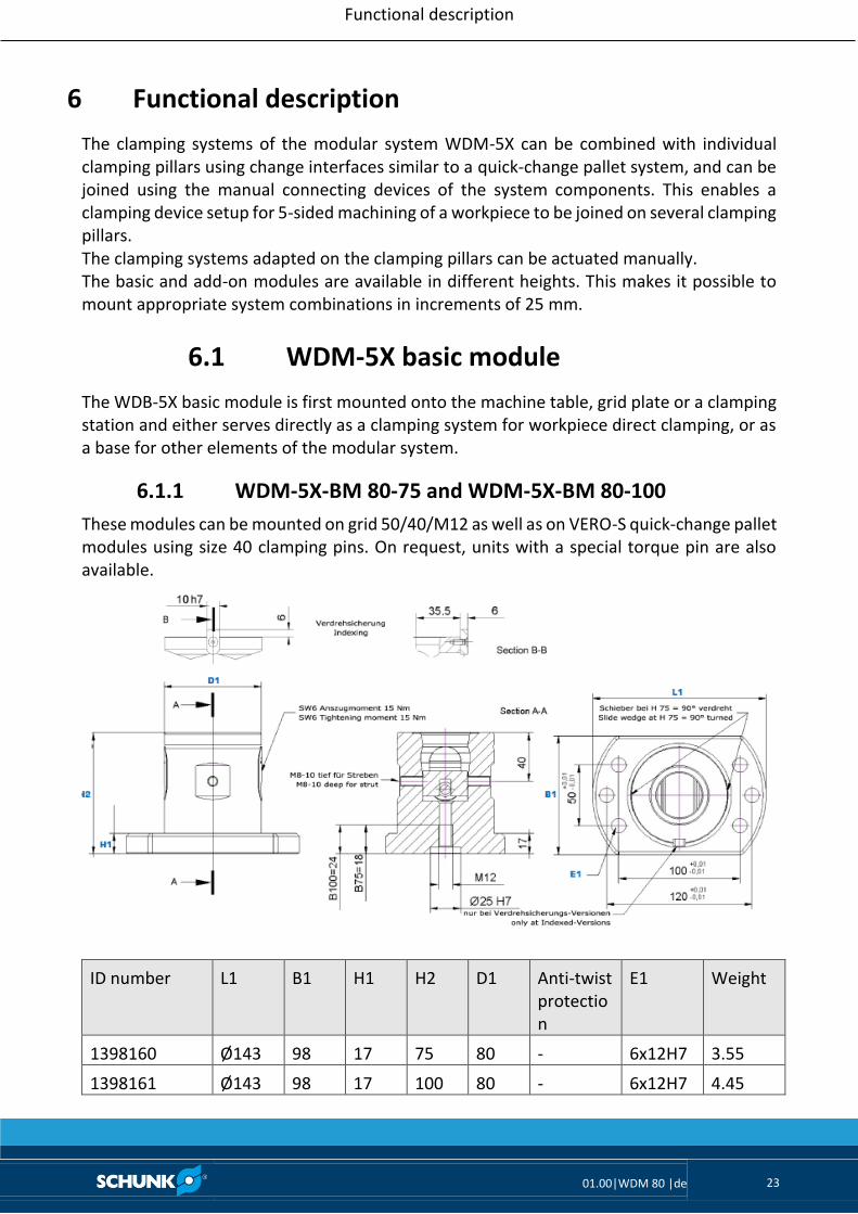
6.1.1 WDM-5X-BM 80-75 and WDM-5X-BM 80-100
These modules can be mounted on grid 50/40/M12 as well as on VERO-S quick-change pallet modules using size 40 clamping pins. On request, units with a special torque pin are also available.
ID number L1 B1 H1 H2 D1 Anti-twist protection
E1 Weight
1398160 Ø143 98 17 75 80 - 6x12H7 3.55
1398161 Ø143 98 17 100 80 - 6x12H7 4.45

Functional description
01.00|WDM 80 |de 24
6.1.2 WDM-5X-BM 80-125, WDM-5X-BM 80-150, WDM-5X-BM 80-175
These modules can be assembled on 50/100/M12-M16 grids, as well as on T-slot tables. The large base feet support flexible assembly.
ID number L1 B1 H1 H2 D1 Anti-twist protection
E1 Weight
1398162 Ø168 130 26 125 80 - 6x12H7 6.65
1398163 Ø168 130 26 150 80 - 6x12H7 7.60
1398164 Ø168 130 26 175 80 - 6x12H7 8.45
6.1.3 WDM-5X-BDM 80-125
This module with double clamping has two clamping areas for mounting a size 40 clamping pin from above and from below.
ID number L1 B1 H1 H2 D1 Anti-twist protection
E1 Weight
1398171 Ø143 98 17 125 80 - 6x12H7 5.00
Functional description
01.00|WDM 80 |de 25
6.2 WDM-5X Basic heigh extension
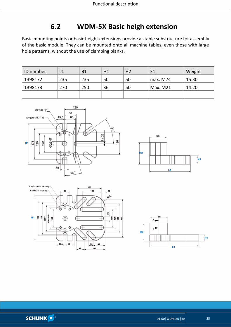
Basic mounting points or basic height extensions provide a stable substructure for assembly of the basic module. They can be mounted onto all machine tables, even those with large hole patterns, without the use of clamping blanks.
ID number L1 B1 H1 H2 E1 Weight
1398172 235 235 50 50 max. M24 15.30
1398173 270 250 36 50 Max. M21 14.20
Weight M12 T25
deep
deep

Functional description
01.00|WDM 80 |de 26
6.3 WDM-5X Add-on module
6.3.1 WDM-5X-SM 80-75
This module is used to raise the height of the basic module. This makes it easy to clamp hard-to-reach workpieces in different heights.
ID number H1 H2 D1 Anti-twist protection
E1 Weight
1398181 11 75 80 - SBA 16 2.85
1398182 11 100 80 - SBA 16 3.65
1398183 11 125 80 - SBA 16 4.70

Functional description
01.00|WDM 80 |de 27
6.3.2 WDM-5X-SDM 80-125 (double clamping module)
This add-on module can be used as a connection for various 5X elements. It is available as a basic module for assembly on machine tables/grid plates.
ID number H1 D1 Anti-twist protection
E1 Weight
1398181 125 80 - 2x SBA 16 4.5

Functional description
01.00|WDM 80 |de 28
6.4 WDM-5X Reduction adapter
6.4.1 Reduction adapter SBA-VL
The reduction adapters implement optimum workpiece accessibility at the machining area. This makes it possible to clamp small bearing surfaces. The soft versions enable machining for any application. The adapters can be positioned using fitting screws or centering collars.
ID number H1 D1 Version Adjustable E1 Weight
1398227 50 80/40 hard - SBA / Ø 16H6 1.00
1398228 50 80/27 hard Arbor/ring Ø2716 SBA / Ø 16H6 1.00
ID number H1 H2 D1 Version E1 Weight
1398229 25 60 80/50 soft SBA 16 / M12x75 1.20
1398230 50 90 80/50 soft SBA 16 / M12x100 1.50

Functional description
01.00|WDM 80 |de 29
6.4.2 Height-adjustable adapter SBA-HE
This adapter compensates for different heights during workpiece clamping. Only one adapter is required to enable heights between 50 mm and 75 mm.
ID number H1 H2 D1 Indexing E1 Weight
1398307 50 75 80 - SBA M20 1.45

Functional description
01.00|WDM 80 |de 30
6.4.3 Plane grip adapter SBA-VLK
The plane grip adapter with star-shaped gripping surface supports milling of small components from all directions. Mounting is performed using an M10 mounting thread via the clamping pin.
ID number H1 H2 D1 Anti-twist protection
E1 Weight
1398308 75 110 80/20 10h7 SBA M20 1.30
6.4.4 Collet chuck adapter SBA-SEZ
Adapter for clamping shafts and round workpieces in collet chucks of size ER50.
ID number H1 H2 D1 D2 D3 Anti-twist protection
E1 Weight
1398309 approx. 100
approx. 135
80 87 78 10h7 SBA M20 2.00
Stop
Fuse

Operation
01.00|WDM 80 |de 31
7 Operation
WARNING
Risk of injury due to losing pallets or workpieces during turning application. • The danger zone must be surrounded by a protective
enclosure during operation. • Do not use the clamping systems on lathes. • The clamping systems are only permitted for stationary
applications with low turning and rotational motions of the clamping structure.
WARNING
Risk of injury due to falling parts during transport of the quick-change pallet system, when the axis of the clamping pin is in a horizontal position, or in the case of overhead application • Use a crane for transportation. • In the case of overhead application, or if the system is in a
horizontal position, secure the pallets or workpieces so that they do not fall when releasing the clamping module.
CAUTION
There is a risk of limbs being crushed by moving parts during manual loading and unloading and the clamping procedure. • Do not reach into the clamping pin holder. • Use loading devices. • Wear protective gloves.
CAUTION
For manual loading and unloading using a crane, there is a danger of damage to the clamping systems by tilting. Do not tilt the workpiece clamping structures when loading and unloading manually.

Maintenance and care
01.00|WDM 80 |de 32
8 Maintenance and care
The clamping systems for workpiece direct clamping VERO-S WDM-5X are designed for low-maintenance operation, meaning it is only necessary to open and disassemble the clamping systems and clamping modules under exceptional circumstances. If it is necessary to disassemble the quick-change pallet system, this may only be performed by trained specialist personnel.
• Clean all the parts thoroughly and check for damage and wear. Damaged and worn parts must be replaced.
• Grease the sliding surfaces of all the other movable components with Renolit HLT 2. Replace damaged parts with original SCHUNK spare parts only. A functional check must be conducted before commissioning.
General operating conditions • Make sure that the contact surfaces of the interface are always clean.
• Always ensure that no chips of any kind enter the interface of the change components.
• Only use high-quality cooling emulsions with anti-corrosive additives during processing.
• Check the clamping systems at regular intervals (at least every two weeks or after 100 clamping operations). Perfect operation is the case whenever the clamping slides move smoothly without increased application of force when actuated by means of the clamping screw.
• Carry out regular visual/functional checks. In case of visible damage or signs of malfunction on the clamping systems, shut it down immediately. The system may only be commissioned again once the faults have been removed. For example, by replacing the damaged unit.

Troubleshooting
01.00|WDM 80 |de 33
9 Troubleshooting
The chuck jaws on the modules no longer clamp properly
Possible cause Remedial measures
The spindle rotation is stiff Clean the spindle and ensure that movement is not impaired
The hexagonal drive on the spindle is defective
Replace the spindle
Flat work surface between the modules not achieved
Clean component at the contact surfaces.
If the clamping area does not unlock perfectly
Possible cause Remedial measures
The module is not lubricated sufficiently Disassemble, clean and relubricate the module (see chapter 8)
The clamping slide or movement mechanism is damaged
Disassemble the module, replace damaged and worn parts with original SCHUNK spare parts (see chapter 8)
A component is broken (e.g. due to overloading)
Replace the module or send it to SCHUNK for repair
Excess tensile load on clamping pins Reduce support weight
Clamping pins locked Be aware of the direction of rotation for unlocking on the manual direct clamping module
Clamping module not completely opened Turn manually in the direction of the "UNLOCK" marking on the drive until you reach the end position

Parts lists
01.00|WDM 80 |de 34
10 Parts lists
10.1 Basic modules
WDM-5X-BM 80-75 (ID no. 1398160)
Item Characterization Quantity
1 Base body 1
2 Right chuck jaw 1
3 Left chuck jaw 1
4 Compensation part 1
5 Spindle 1
6 Needle roller 2
8 Set-screw 2
9 Screw, DIN EN 4762 2
WDM-5X-BM 80-100 (ID no. 1398161)
Item Characterization Quantity
1 Base body 1
2 Right chuck jaw 1
3 Left chuck jaw 1
4 Compensation part 1
5 Spindle 1
6 Needle roller 2
8 Set-screw 2
9 Screw, DIN EN 4762 2
WDM-5X-BM 80-125 (ID no. 1398162)
Item Characterization Quantity
1 Base body 1
2 Right chuck jaw 1
3 Left chuck jaw 1
4 Compensation part 1
5 Spindle 1
6 Needle roller 2
8 Set-screw 2
9 Screw, DIN EN 4762 2

Parts lists
01.00|WDM 80 |de 35
WDM-5X-BM 80-150 (ID no. 1398163)
Item Characterization Quantity
1 Base body 1
2 Right chuck jaw 1
3 Left chuck jaw 1
4 Compensation part 1
5 Spindle 1
6 Needle roller 2
8 Set-screw 2
9 Screw, DIN EN 4762 2
WDM-5X-BM 80-175 (ID no. 1398164)
Item Characterization Quantity
1 Base body 1
2 Right chuck jaw 1
3 Left chuck jaw 1
4 Compensation part 1
5 Spindle 1
6 Needle roller 2
8 Set-screw 2
9 Screw, DIN EN 4762 2
WDM-5X-BDM 80-125 (ID no. 1398171)
Item Characterization Quantity
1 Base body 1
2 Right chuck jaw 2
3 Left chuck jaw 2
4 Compensation part 2
5 Spindle 2
6 Needle roller 4
8 Set-screw 4

Parts lists
01.00|WDM 80 |de 36
10.2 Height extension for basic module
WDM-5X-BP 235-235-50 (ID no. 1398172)
Item Characterization Quantity
1 Base body 1
WDM-5X-BP 270-250-36 (ID no. 1398173)
Item Characterization Quantity
1 Base body 1
10.3 Add-on modules
WDM-5X-SM 80-75 (ID no. 1398181)
Item Characterization Quantity
1 Base body 1
2 Right chuck jaw 1
3 Left chuck jaw 1
4 Compensation part 1
5 Spindle 1
6 Needle roller 2
8 Set-screw 2
9 Screw, DIN EN 4762 1
10 Clamping pin SBA 1
WDM-5X-SM 80-100 (ID no. 1398182)
Item Characterization Quantity
1 Base body 1
2 Right chuck jaw 1
3 Left chuck jaw 1
4 Compensation part 1
5 Spindle 1
6 Needle roller 2
8 Set-screw 2
9 Screw, DIN EN 4762 1
10 Clamping pin SBA 1

Parts lists
01.00|WDM 80 |de 37
WDM-5X-SM 80-125 (ID no. 1398183)
Item Characterization Quantity
1 Base body 1
2 Right chuck jaw 1
3 Left chuck jaw 1
4 Compensation part 1
5 Spindle 1
6 Needle roller 2
8 Set-screw 2
9 Screw, DIN EN 4762 1
10 Clamping pin SBA 1
WDM-5X-SDM 80-125 (ID no. 1398184)
Item Characterization Quantity
1 Base body 1
2 Right chuck jaw 2
3 Left chuck jaw 2
4 Compensation part 2
5 Spindle 2
6 Needle roller 4
8 Set-screw 4
10.4 Reduction adapter
SBA-VL-P 50-M16 (ID no. 1398227)
Item Characterization Quantity
1 Base body 1
SBA-VL-PA 50-M16 (ID no. 1398228)
Item Characterization Quantity
1 Base body 1
SBA-VL 25-M12 (ID no. 1398229)
Item Characterization Quantity
1 Base body 1
2 Screw, DIN EN 4762 1
3 Clamping pin SBA 1
Parts lists
01.00|WDM 80 |de 38
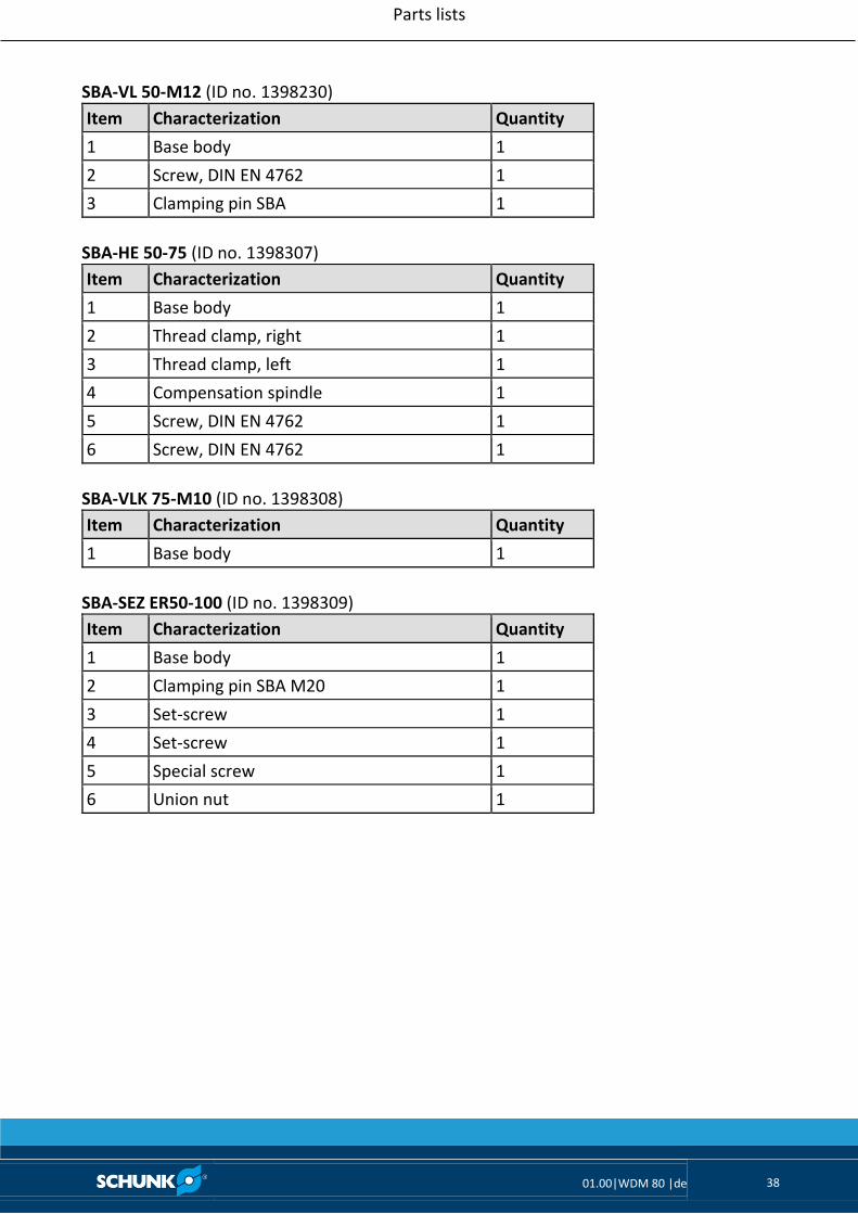
SBA-VL 50-M12 (ID no. 1398230)
Item Characterization Quantity
1 Base body 1
2 Screw, DIN EN 4762 1
3 Clamping pin SBA 1
SBA-HE 50-75 (ID no. 1398307)
Item Characterization Quantity
1 Base body 1
2 Thread clamp, right 1
3 Thread clamp, left 1
4 Compensation spindle 1
5 Screw, DIN EN 4762 1
6 Screw, DIN EN 4762 1
SBA-VLK 75-M10 (ID no. 1398308)
Item Characterization Quantity
1 Base body 1
SBA-SEZ ER50-100 (ID no. 1398309)
Item Characterization Quantity
1 Base body 1
2 Clamping pin SBA M20 1
3 Set-screw 1
4 Set-screw 1
5 Special screw 1
6 Union nut 1

Assembly drawings
01.00|WDM 80 |de 39
11 Assembly drawings
Basic module type A Basic module type B
Assembly drawings
01.00|WDM 80 |de 40
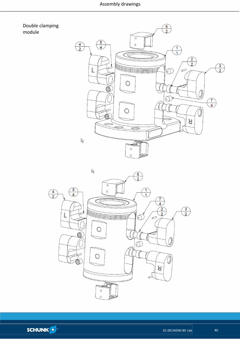
Double clamping module

Assembly drawings
01.00|WDM 80 |de 41
Add-on module