version 1 - media.kieskeurig.nl
TRANSCRIPT


Version 1.0 Published September 2018 Copyright©2018 ASRock INC. All rights reserved.
Copyright Notice:No part of this documentation may be reproduced, transcribed, transmitted, or translated in any language, in any form or by any means, except duplication of documentation by the purchaser for backup purpose, without written consent of ASRock Inc.
Products and corporate names appearing in this documentation may or may not be registered trademarks or copyrights of their respective companies, and are used only for identification or explanation and to the owners’ benefit, without intent to infringe.
Disclaimer:Specifications and information contained in this documentation are furnished for informational use only and subject to change without notice, and should not be constructed as a commitment by ASRock. ASRock assumes no responsibility for any errors or omissions that may appear in this documentation.
With respect to the contents of this documentation, ASRock does not provide warranty of any kind, either expressed or implied, including but not limited to the implied warranties or conditions of merchantability or fitness for a particular purpose.
In no event shall ASRock, its directors, officers, employees, or agents be liable for any indirect, special, incidental, or consequential damages (including damages for loss of profits, loss of business, loss of data, interruption of business and the like), even if ASRock has been advised of the possibility of such damages arising from any defect or error in the documentation or product.
This device complies with Part 15 of the FCC Rules. Operation is subject to the following two conditions: (1) this device may not cause harmful interference, and (2) this device must accept any interference received, including interference that
may cause undesired operation.
CALIFORNIA, USA ONLYThe Lithium battery adopted on this motherboard contains Perchlorate, a toxic substance controlled in Perchlorate Best Management Practices (BMP) regulations passed by the California Legislature. When you discard the Lithium battery in California, USA, please follow the related regulations in advance.“Perchlorate Material-special handling may apply, see www.dtsc.ca.gov/hazardouswaste/perchlorate”
ASRock Website: http://www.asrock.com

AUSTRALIA ONLYOur goods come with guarantees that cannot be excluded under the Australian Consumer Law. You are entitled to a replacement or refund for a major failure and compensation for any other reasonably foreseeable loss or damage caused by our goods. You are also entitled to have the goods repaired or replaced if the goods fail to be of acceptable quality and the failure does not amount to a major failure. If you require assistance please call ASRock Tel : +886-2-28965588 ext.123 (Standard International call charges apply) The terms HDMI® and HDMI High-Definition Multimedia Interface, and the HDMI logo are trademarks or registered trademarks of HDMI Licensing LLC in the United States and other countries.

Contents
Chapter 1 Introduction 1
1.1 Package Contents 1
1.2 Specifications 2
1.3 Motherboard Layout 7
1.4 I/O Panel 10
Chapter 2 Installation 13
2.1 Installing the CPU 14
2.2 Installing the CPU Fan and Heatsink 16
2.3 Installing Memory Modules (DIMM) 24
2.4 Expansion Slots (PCI Express Slots) 27
2.5 Jumpers Setup 28
2.6 Onboard Headers and Connectors 29
2.7 M.2_SSD (NGFF) Module Installation Guide (for X370M-HDV R4.0 / AB350M-HDV R4.0 / A320M-HDV R4.0 only) 33
Chapter 3 Software and Utilities Operation 37
3.1 Installing Drivers 37
3.2 A-Tuning 38
3.2.1 Installing A-Tuning 38
3.2.2 Using A-Tuning 38
3.3 ASRock Live Update & APP Shop 41
3.3.1 UI Overview 41
3.3.2 Apps 42
3.3.3 BIOS & Drivers 45

3.3.4 Setting 46
Chapter 4 UEFI SETUP UTILITY 47
4.1 Introduction 47
4.1.1 UEFI Menu Bar 47
4.1.2 Navigation Keys 48
4.2 Main Screen 49
4.3 OC Tweaker Screen 50
4.4 Advanced Screen 52
4.4.1 CPU Configuration 53
4.4.2 North Bridge Configuration 54
4.4.3 South Bridge Configuration 55
4.4.4 Storage Configuration 56
4.4.5 Super IO Configuration 57
4.4.6 ACPI Configuration 58
4.4.7 Trusted Computing 59
4.4.8 AMD CBS 60
4.4.9 AMD PBS 68
4.5 Tools 69
4.6 Hardware Health Event Monitoring Screen 71
4.7 Security Screen 72
4.8 Boot Screen 73
4.9 Exit Screen 75
X370M-HDV R4.0 / AB350M-HDV R4.0 / A320M-HDV R4.0 / A320M-DVS R4.0
1
Engl
ish
Chapter 1 IntroductionThank you for purchasing ASRock X370M-HDV R4.0 / AB350M-HDV R4.0 / A320M-HDV R4.0 / A320M-DVS R4.0 motherboard, a reliable motherboard produced under ASRock’s consistently stringent quality control. It delivers excellent performance with robust design conforming to ASRock’s commitment to quality and endurance.
In this manual, Chapter 1 and 2 contains the introduction of the motherboard and step-by-step installation guides. Chapter 3 contains the operation guide of the software and utilities. Chapter 4 contains the configuration guide of the BIOS setup.
1.1 Package Contents• ASRock X370M-HDV R4.0 / AB350M-HDV R4.0 / A320M-HDV R4.0 / A320M-DVS
R4.0 Motherboard (Micro ATX Form Factor)• ASRock X370M-HDV R4.0 / AB350M-HDV R4.0 / A320M-HDV R4.0 / A320M-DVS
R4.0 Quick Installation Guide • ASRock X370M-HDV R4.0 / AB350M-HDV R4.0 / A320M-HDV R4.0 / A320M-DVS
R4.0 Support CD • 1 x I/O Panel Shield • 2 x Serial ATA (SATA) Data Cables (Optional)• 1 x Screw for M.2 Socket (Optional) (for X370M-HDV R4.0 / AB350M-HDV R4.0 /
A320M-HDV R4.0 only)
Because the motherboard specifications and the BIOS software might be updated, the content of this manual will be subject to change without notice. In case any modifica-tions of this manual occur, the updated version will be available on ASRock’s website without further notice. If you require technical support related to this motherboard, please visit our website for specific information about the model you are using. You may find the latest VGA cards and CPU support list on ASRock’s website as well. ASRock website http://www.asrock.com.

English
2
1.2 Specifications
Platform • Micro ATX Form Factor• Solid Capacitor design
CPU • Supports AMD Socket AM4 A-Series APUs (Bristol Ridge) and Ryzen Series CPUs (Summit Ridge, Raven Ridge and Pinnacle Ridge)
• 6 Power Phase design• Supports CPU up to 105W
Chipset • AMD Promontory X370 (X370M-HDV R4.0)• AMD Promontory B350 (AB350M-HDV R4.0)• AMD Promontory A320 (A320M-HDV R4.0 / A320M-DVS
R4.0)
Memory • Dual Channel DDR4 Memory Technology• 2 x DDR4 DIMM Slots• AMD Ryzen series CPUs (Pinnacle Ridge) support DDR4
3200+(OC)/2933(OC)/2667/2400/2133 ECC & non-ECC, un-buffered memory*
• AMD Ryzen series CPUs (Summit Ridge) support DDR4 3200+(OC)/2933(OC)/2667/2400/2133 ECC & non-ECC, un-buffered memory*
• AMD Ryzen series CPUs (Raven Ridge) support DDR4 3200+(OC)/2933/2667/2400/2133 non-ECC, un-buffered memory*
• AMD 7th Gen A-Series APUs support DDR4 2400/2133 non-ECC, un-buffered memory*
* For Ryzen Series CPUs (Raven Ridge), ECC is only supported with PRO CPUs.* Please refer to Memory Support List on ASRock’s website for more information. (http://www.asrock.com/)* Please refer to page 24 for DDR4 UDIMM maximum frequency support.• Max. capacity of system memory: 32GB• 15μ Gold Contact in DIMM Slots

X370M-HDV R4.0 / AB350M-HDV R4.0 / A320M-HDV R4.0 / A320M-DVS R4.0
3
Engl
ish
Expansion Slot
AMD Ryzen series CPUs (Summit Ridge and Pinnacle Ridge) • 1 x PCI Express 3.0 x16 Slot (PCIE2: x16 mode)*
AMD 7th A-Series APUs • 1 x PCI Express 3.0 x16 Slot (PCIE2: x8 mode)*
AMD Ryzen series CPUs (Raven Ridge) • 1 x PCI Express 3.0 x16 Slot (PCIE2: x8 mode) (If you use
Athlon 2xxGE series APU, PCIE2 slot will run at x4 mode.)** Supports NVMe SSD as boot disks• 1 x PCI Express 2.0 x1 Slot
Graphics • Integrated AMD RadeonTM Vega Series Graphics in Ryzen Series APU*
• Integrated AMD RadeonTM R-Series Graphics in A-series APU*
* Actual support may vary by CPU• DirectX 12, Pixel Shader 5.0• Shared memory default 2GB, Max Shared memory supports
up to 16GB.* The Max shared memory 16 GB requires 32 GB system memory installed.X370M-HDV R4.0 / AB350M-HDV R4.0 / A320M-HDV R4.0 only:• Three graphics output options: D-Sub, DVI-D and HDMI • Supports Triple Monitor• Supports HDMI with max. resolution up to 4K x 2K
(4096x2160) @ 24Hz / (3840x2160) @ 30Hz• Supports DVI-D with max. resolution up to 1920x1200 @
60Hz• Supports D-Sub with max. resolution up to 2048x1536 @
60Hz• Supports Auto Lip Sync, Deep Color (12bpc), xvYCC and
HBR (High Bit Rate Audio) with HDMI Port (Compliant HDMI monitor is required)
• Supports HDCP with DVI-D and HDMI Ports • Supports Full HD 1080p Blu-ray (BD) playback with DVI-D
and HDMI Ports A320M-DVS R4.0:• Dual graphics output options: support DVI-D and D-Sub by
independent display controllers
English
4
• Supports DVI-D with max. resolution up to 1920x1200 @ 60Hz
• Supports D-Sub with max. resolution up to 2048x1536 @ 60Hz
• Supports HDCP with DVI-D Port• Supports Full HD 1080p Blu-ray (BD) playback with DVI-D
Port
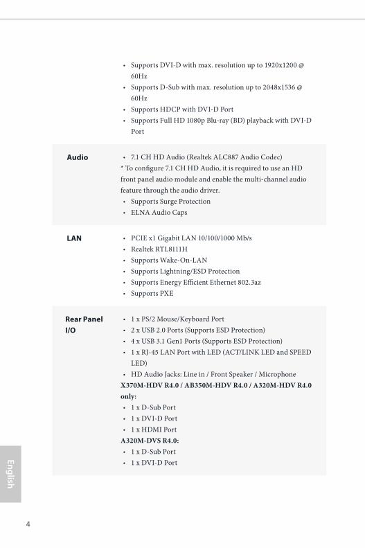
Audio • 7.1 CH HD Audio (Realtek ALC887 Audio Codec) * To configure 7.1 CH HD Audio, it is required to use an HD front panel audio module and enable the multi-channel audio feature through the audio driver.• Supports Surge Protection • ELNA Audio Caps
LAN • PCIE x1 Gigabit LAN 10/100/1000 Mb/s• Realtek RTL8111H• Supports Wake-On-LAN • Supports Lightning/ESD Protection• Supports Energy Efficient Ethernet 802.3az• Supports PXE
Rear Panel I/O
• 1 x PS/2 Mouse/Keyboard Port• 2 x USB 2.0 Ports (Supports ESD Protection)• 4 x USB 3.1 Gen1 Ports (Supports ESD Protection)• 1 x RJ-45 LAN Port with LED (ACT/LINK LED and SPEED
LED)• HD Audio Jacks: Line in / Front Speaker / Microphone
X370M-HDV R4.0 / AB350M-HDV R4.0 / A320M-HDV R4.0 only:• 1 x D-Sub Port • 1 x DVI-D Port• 1 x HDMI Port
A320M-DVS R4.0:• 1 x D-Sub Port • 1 x DVI-D Port

X370M-HDV R4.0 / AB350M-HDV R4.0 / A320M-HDV R4.0 / A320M-DVS R4.0
5
Engl
ish
Storage • 4 x SATA3 6.0 Gb/s Connectors, support RAID (RAID 0, RAID 1 and RAID 10), NCQ, AHCI and Hot Plug
• 1 x Ultra M.2 Socket, supports M Key type 2242/2260/2280 M.2 SATA3 6.0 Gb/s module and M.2 PCI Express module up to Gen3 x4 (32 Gb/s) (with Summit Ridge, Raven Ridge and Pinnacle Ridge) or Gen3 x2 (16 Gb/s)(with A-Series APU and Athlon 2xxGE series APU)* (for X370M-HDV R4.0 / AB350M-HDV R4.0 / A320M-HDV R4.0 only)
* Supports NVMe SSD as boot disks* Supports ASRock U.2 Kit
Connector • 1 x COM Port Header• 1 x TPM Header• 1 x Chassis Intrusion and Speaker Header• 1 x CPU Fan Connector (4-pin)• 2 x Chassis Fan Connectors (1 x 4-pin, 1 x 3-pin)
* The CPU Fan Connector supports the CPU fan of maximum 1A (12W) fan power. • 1 x 24 pin ATX Power Connector• 1 x 4 pin 12V Power Connector• 1 x Front Panel Audio Connector • 2 x USB 2.0 Headers (Support 4 USB 2.0 ports) (Supports ESD
Protection)• 1 x USB 3.1 Gen1 Header (Supports 2 USB 3.1 Gen1 ports)
(Supports ESD Protection)
BIOS Feature
• AMI UEFI Legal BIOS with GUI support• Supports “Plug and Play”• ACPI 5.1 compliance wake up events• Supports jumperfree• SMBIOS 2.3 support• DRAM Voltage multi-adjustment
Hardware Monitor
• CPU/Chassis temperature sensing• CPU/Chassis Fan Tachometer• CPU/Chassis Quiet Fan• CPU/Chassis Fan multi-speed control• CASE OPEN detection• Voltage monitoring: +12V, +5V, +3.3V, Vcore

English
6
OS • Microsoft® Windows® 10 64-bit
Certifica-tions
• FCC, CE• ErP/EuP ready (ErP/EuP ready power supply is required)
* For detailed product information, please visit our website: http://www.asrock.com
Please realize that there is a certain risk involved with overclocking, including adjust-ing the setting in the BIOS, applying Untied Overclocking Technology, or using third-party overclocking tools. Overclocking may affect your system’s stability, or even cause damage to the components and devices of your system. It should be done at your own risk and expense. We are not responsible for possible damage caused by overclocking.
X370M-HDV R4.0 / AB350M-HDV R4.0 / A320M-HDV R4.0 / A320M-DVS R4.0
7
Engl
ish
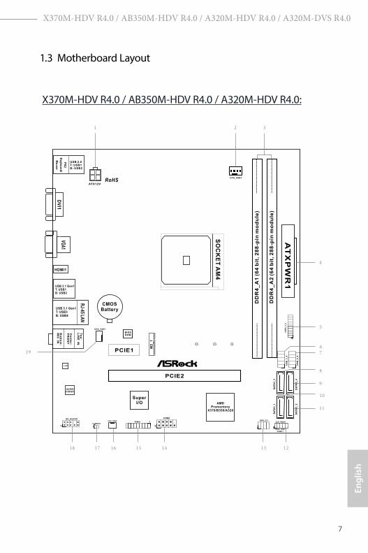
1.3 Motherboard Layout
BIOSROM
AT
XP
WR
1
FS
B8
00
DD
R4
_A
1 (
64
bit
, 2
88
-pin
mo
du
le)
DD
R4
_A
2 (
64
bit
, 2
88
-pin
mo
du
le)
SuperI/O
LAN
AUDIOCODEC
PCIE2
PCIE1
US
B_
3_
4
US
B_
5_
6
HD_AUDIO1
1
CPU_FAN1
1
COM1
3
4
2
9
5
USB 2.0T: USB1B: USB2
PS
2
Ke
yb
oa
rd/
Mo
us
e
CMOSBattery
1
US
B3
_5
_6
1
CHA_FAN2
HDLED RESET
PLED PWRBTN
PANEL1
1
RoHS
1518 16 13 1214
19
SPK_CI1
1
USB 3.1 Gen1T: USB1B: USB2
To
p:
LIN
E IN
Ce
nte
r:
FR
ON
T
Bo
ttom
:M
IC IN
RJ-45 LA
N
USB 3.1 Gen1T: USB3B: USB4
TPMS1 1
HDMI1
ATX12V
7
8
6
CLRMOS1
1
SA
TA
3_
3
SA
TA
3_
4
AMDPromontory
X370/B350/A320
SO
CK
ET
AM
4
CHA_FAN1
11
10
SA
TA
3_
1
SA
TA
3_
2
17
M2
_1
X370M-HDV R4.0 / AB350M-HDV R4.0 / A320M-HDV R4.0:

English
8
BIOSROM
FS
B8
00
DD
R4
_A
1 (
64
bit
, 2
88
-pin
mo
du
le)
DD
R4
_A
2 (
64
bit
, 2
88
-pin
mo
du
le)
SuperI/O
LAN
AUDIOCODEC
PCIE2
PCIE1
US
B_
3_
4
US
B_
5_
6
HD_AUDIO1
1
CPU_FAN1
1
COM1
3
4
2
9
5
USB 2.0T: USB1B: USB2
PS
2
Ke
yb
oa
rd/
Mo
us
e
CMOSBattery
1
US
B3
_5
_6
1
CHA_FAN2
HDLED RESET
PLED PWRBTN
PANEL1
1
RoHS
1518 16 13 1214
19
SPK_CI1
1
USB 3.1 Gen1T: USB1B: USB2
To
p:
LIN
E IN
Ce
nte
r:
FR
ON
T
Bo
ttom
:M
IC IN
TPMS1 1
ATX12V
7
8
6
CLRMOS1
1
SA
TA
3_
3
SA
TA
3_
4
AMDPromontory
A320
SO
CK
ET
AM
4
CHA_FAN1
11
10
SA
TA
3_
1
SA
TA
3_
2
17
A320M-DVS
RJ-45 LA
N
USB 3.1 Gen1T: USB3B: USB4
AT
XP
WR
1
A320M-DVS R4.0:

X370M-HDV R4.0 / AB350M-HDV R4.0 / A320M-HDV R4.0 / A320M-DVS R4.0
9
Engl
ish
No. Description
1 ATX 12V Power Connector (ATX12V1)
2 CPU Fan Connector (CPU_FAN1)
3 2 x 288-pin DDR4 DIMM Slots (DDR4_A1, DDR4_A2)
4 ATX Power Connector (ATXPWR1)
5 USB 3.1 Gen1 Header (USB3_5_6)
6 USB 2.0 Header (USB_3_4)
7 USB 2.0 Header (USB_5_6)
8 SATA3 Connector (SATA3_3)
9 SATA3 Connector (SATA3_4)
10 SATA3 Connector (SATA3_1)
11 SATA3 Connector (SATA3_2)
12 System Panel Header (PANEL1)
13 Chassis Intrusion and Speaker Header (SPK_CI1)
14 COM Port Header (COM1)
15 TPM Header (TPMS1)
16 Chassis Fan Connector (CHA_FAN2)
17 Clear CMOS Jumper (CLRCMOS1)
18 Front Panel Audio Header (HD_AUDIO1)
19 Chassis Fan Connector (CHA_FAN1)

English
10
1.4 I/O Panel
X370M-HDV R4.0 / AB350M-HDV R4.0 / A320M-HDV R4.0:
No. Description No. Description
1 USB 2.0 Ports (USB12) 7 USB 3.1 Gen1 Ports (USB3_12)
2 LAN RJ-45 Port* 8 HDMI Port
3 Line In (Light Blue)** 9 D-Sub Port
4 Front Speaker (Lime)** 10 DVI-D Port
5 Microphone (Pink)** 11 PS/2 Mouse/Keyboard Port
6 USB 3.1 Gen1 Ports (USB3_34)
1 2 4
5678911 10
3

X370M-HDV R4.0 / AB350M-HDV R4.0 / A320M-HDV R4.0 / A320M-DVS R4.0
11
Engl
ish
A320M-DVS R4.0:
1 USB 2.0 Ports (USB12) 6 USB 3.1 Gen1 Ports (USB3_34)
2 LAN RJ-45 Port* 7 USB 3.1 Gen1 Ports (USB3_12)
3 Line In (Light Blue)** 8 D-Sub Port
4 Front Speaker (Lime)** 9 DVI-D Port
5 Microphone (Pink)** 10 PS/2 Mouse/Keyboard Port
* There are two LEDs on each LAN port. Please refer to the table below for the LAN port LED indications.
Activity / Link LED Speed LED
Status Description Status DescriptionOff No Link Off 10Mbps connectionBlinking Data Activity Orange 100Mbps connectionOn Link Green 1Gbps connection
ACT/LINK LED
SPEED LED
LAN Port
1 2 4
567810 9
3

English
12
** To configure 7.1 CH HD Audio, it is required to use an HD front panel audio module and enable the multi-channel audio feature through the audio driver.
Please set Speaker Configuration to “7.1 Speaker”in the Realtek HD Audio Manager.
Function of the Audio Ports in 7.1-channel Configuration:
Port FunctionLight Blue (Rear panel) Rear Speaker OutLime (Rear panel) Front Speaker OutPink (Rear panel) Central /Subwoofer Speaker OutLime (Front panel) Side Speaker Out

X370M-HDV R4.0 / AB350M-HDV R4.0 / A320M-HDV R4.0 / A320M-DVS R4.0
13
Engl
ish
This is a Micro ATX form factor motherboard. Before you install the motherboard, study the configuration of your chassis to ensure that the motherboard fits into it.
Pre-installation PrecautionsTake note of the following precautions before you install motherboard components or change any motherboard settings.
• Make sure to unplug the power cord before installing or removing the motherboard. Failure to do so may cause physical injuries to you and damages to motherboard components.
• In order to avoid damage from static electricity to the motherboard’s components, NEVER place your motherboard directly on a carpet. Also remember to use a grounded wrist strap or touch a safety grounded object before you handle the components.
• Hold components by the edges and do not touch the ICs.• Whenever you uninstall any components, place them on a grounded anti-static pad or
in the bag that comes with the components.• When placing screws to secure the motherboard to the chassis, please do not over-
tighten the screws! Doing so may damage the motherboard.
Chapter 2 Installation

English
14
2.1 Installing the CPU
Unplug all power cables before installing the CPU.
2
1

X370M-HDV R4.0 / AB350M-HDV R4.0 / A320M-HDV R4.0 / A320M-DVS R4.0
15
Engl
ish
3

English
16
2.2 Installing the CPU Fan and HeatsinkAfter you install the CPU into this motherboard, it is necessary to install a larger heatsink and cooling fan to dissipate heat. You also need to spray thermal grease between the CPU and the heatsink to improve heat dissipation. Make sure that the CPU and the heatsink are securely fastened and in good contact with each other.
Installing the CPU Box Cooler SR1
Please turn off the power or remove the power cord before changing a CPU or heatsink.
1
2

X370M-HDV R4.0 / AB350M-HDV R4.0 / A320M-HDV R4.0 / A320M-DVS R4.0
17
Engl
ish
3
4
CPU_FAN1
4-pin FAN cable

English
18
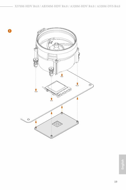
Installing the AM4 Box Cooler SR2
1
2
X370M-HDV R4.0 / AB350M-HDV R4.0 / A320M-HDV R4.0 / A320M-DVS R4.0
19
Engl
ish
3

English
20
4-pin FAN cable
4
CPU_FAN1

X370M-HDV R4.0 / AB350M-HDV R4.0 / A320M-HDV R4.0 / A320M-DVS R4.0
21
Engl
ish
Installing the AM4 Box Cooler SR3
1
2

English
22
3
4

X370M-HDV R4.0 / AB350M-HDV R4.0 / A320M-HDV R4.0 / A320M-DVS R4.0
23
Engl
ish
5
CPU_FAN1
Please note that this connector is the interface to the LED control board on the SR3, it requires the AMD utility "SR3 Settings Software" to control the LED. *The diagram shown here are for reference only. Please refer to page 31 for the orientation of USB Header.
CPU_FAN1
6
USB
4-pin FAN cable
USB 2.0 Header

English
24
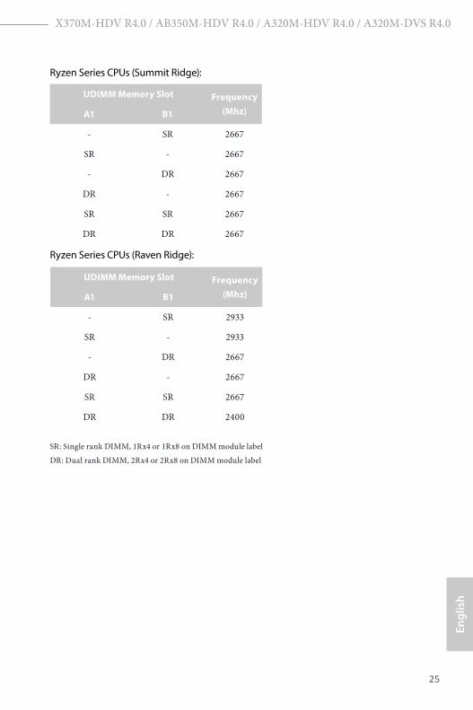
2.3 Installing Memory Modules (DIMM)
This motherboard provides two 288-pin DDR4 (Double Data Rate 4) DIMM slots, and supports Dual Channel Memory Technology.
DDR4 UDIMM Maximum Frequency Support
A-Series APUs:
Ryzen Series CPUs (Pinnacle Ridge):
1. For dual channel configuration, you always need to install identical (the same brand, speed, size and chip-type) DDR4 DIMM pairs.
2. It is unable to activate Dual Channel Memory Technology with only one memory module installed.
3. It is not allowed to install a DDR, DDR2 or DDR3 memory module into a DDR4 slot; otherwise, this motherboard and DIMM may be damaged.
UDIMM Memory Slot Frequency (Mhz)A1 B1
- SR 2400
SR - 2400
- DR 2400
DR - 2400
SR SR 2400
DR DR 2400
UDIMM Memory Slot Frequency (Mhz)A1 B1
- SR 2667
SR - 2667
- DR 2400
DR - 2400
SR SR 2667
DR DR 2400
X370M-HDV R4.0 / AB350M-HDV R4.0 / A320M-HDV R4.0 / A320M-DVS R4.0
25
Engl
ish
Ryzen Series CPUs (Summit Ridge):
Ryzen Series CPUs (Raven Ridge):
SR: Single rank DIMM, 1Rx4 or 1Rx8 on DIMM module label
DR: Dual rank DIMM, 2Rx4 or 2Rx8 on DIMM module label
UDIMM Memory Slot Frequency (Mhz)A1 B1
- SR 2667
SR - 2667
- DR 2667
DR - 2667
SR SR 2667
DR DR 2667
UDIMM Memory Slot Frequency (Mhz)A1 B1
- SR 2933
SR - 2933
- DR 2667
DR - 2667
SR SR 2667
DR DR 2400
English
26
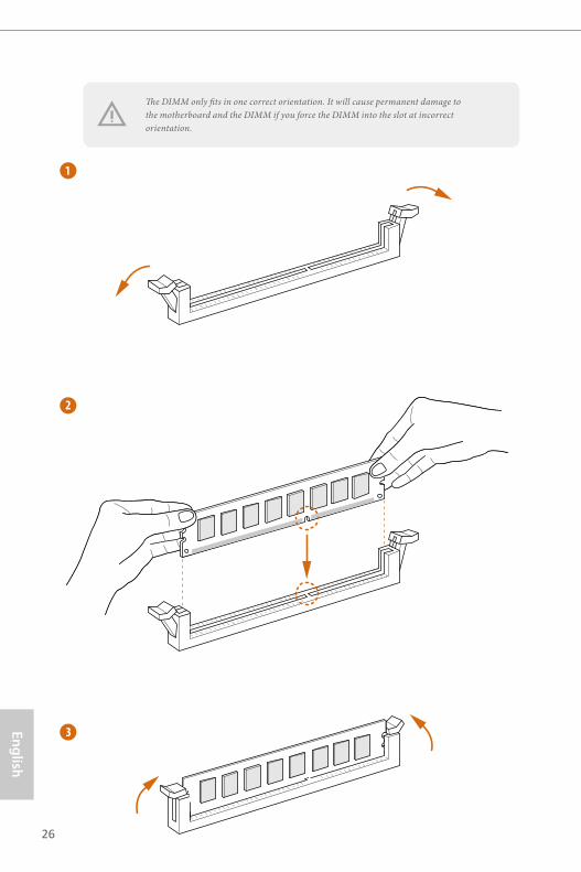
1
2
3
The DIMM only fits in one correct orientation. It will cause permanent damage to the motherboard and the DIMM if you force the DIMM into the slot at incorrect orientation.

X370M-HDV R4.0 / AB350M-HDV R4.0 / A320M-HDV R4.0 / A320M-DVS R4.0
27
Engl
ish
2.4 Expansion Slots (PCI Express Slots)There are 2 PCI Express slots on the motherboard.
PCIe slots:
PCIE1 (PCIe 2.0 x1 slot) is used for PCI Express x1 lane width cards PCIE2 (PCIe 3.0 x16 slot) is used for PCI Express x16 lane width graphics cards.
PCIe Slot Configurations
Before installing an expansion card, please make sure that the power supply is switched off or the power cord is unplugged. Please read the documentation of the expansion card and make necessary hardware settings for the card before you start the installation.
CPU PCIE2
Ryzen series CPUs (Pinnacle Ridge) x16
Ryzen series CPUs (Summit Ridge) x16
Ryzen series CPUs (Raven Ridge) x8
Athlon 2xxGE series APU x4
7th A-Series APUs x8
For a better thermal environment, please connect a chassis fan to the motherboard’s chassis fan connector (CHA_FAN1 or CHA_FAN2 ) when using multiple graphics cards.
English
28
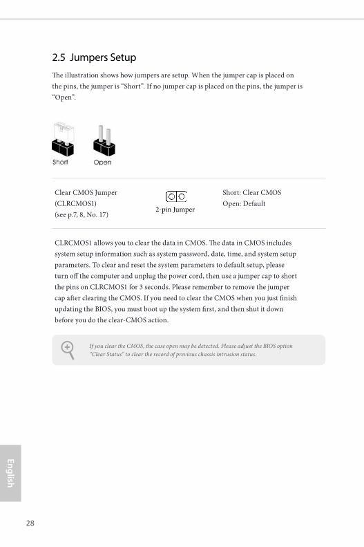
If you clear the CMOS, the case open may be detected. Please adjust the BIOS option “Clear Status” to clear the record of previous chassis intrusion status.
2.5 Jumpers SetupThe illustration shows how jumpers are setup. When the jumper cap is placed on the pins, the jumper is “Short”. If no jumper cap is placed on the pins, the jumper is “Open”.
Clear CMOS Jumper(CLRCMOS1)(see p.7, 8, No. 17)
Short: Clear CMOS Open: Default
CLRCMOS1 allows you to clear the data in CMOS. The data in CMOS includes system setup information such as system password, date, time, and system setup parameters. To clear and reset the system parameters to default setup, please turn off the computer and unplug the power cord, then use a jumper cap to short the pins on CLRCMOS1 for 3 seconds. Please remember to remove the jumper cap after clearing the CMOS. If you need to clear the CMOS when you just finish updating the BIOS, you must boot up the system first, and then shut it down before you do the clear-CMOS action.
2-pin Jumper

X370M-HDV R4.0 / AB350M-HDV R4.0 / A320M-HDV R4.0 / A320M-DVS R4.0
29
Engl
ish
2.6 Onboard Headers and Connectors
System Panel Header(9-pin PANEL1)(see p.7, 8, No. 12)
Connect the power button, reset button and system status indicator on the chassis to this header according to the pin assignments below. Note the positive and negative pins before connecting the cables.
Onboard headers and connectors are NOT jumpers. Do NOT place jumper caps over these headers and connectors. Placing jumper caps over the headers and connectors will cause permanent damage to the motherboard.
GND
RESET#
PWRBTN#
PLED-
PLED+
GND
HDLED-
HDLED+
1
GND
PWRBTN (Power Button): Connect to the power button on the chassis front panel. You may configure the way to turn off your system using the power button.
RESET (Reset Button): Connect to the reset button on the chassis front panel. Press the reset button to restart the computer if the computer freezes and fails to perform a normal restart.
PLED (System Power LED): Connect to the power status indicator on the chassis front panel. The LED is on when the system is operating. The LED keeps blinking when the system is in S1/S3 sleep state. The LED is off when the system is in S4 sleep state or powered off (S5).
HDLED (Hard Drive Activity LED): Connect to the hard drive activity LED on the chassis front panel. The LED is on when the hard drive is reading or writing data.
The front panel design may differ by chassis. A front panel module mainly consists of power button, reset button, power LED, hard drive activity LED, speaker and etc. When connect-ing your chassis front panel module to this header, make sure the wire assignments and the pin assignments are matched correctly.

English
30
Chassis Intrusion and Speaker Header(7-pin SPK_CI1)(see p.7, 8, No. 13)
Please connect the chassis intrusion and the chassis speaker to this header.
Serial ATA3 Connectors(SATA3_1: see p.7, 8, No. 10)(SATA3_2: see p.7, 8, No. 11)(SATA3_3: see p.7, 8, No. 8)(SATA3_4: see p.7, 8, No. 9)
These four SATA3 connectors support SATA data cables for internal storage devices with up to 6.0 Gb/s data transfer rate.
USB 2.0 Header(9-pin USB_3_4)(see p.7, 8, No. 6)(9-pin USB_5_6)(see p.7, 8, No. 7)
There are two headers on this motherboard. Each USB 2.0 header can support two ports.
USB 3.1 Gen1 Header(19-pin USB3_5_6)(see p.7, 8, No. 5)
There is one header on this motherboard. Each USB 3.1 Gen1 header can support two ports.
Front Panel Audio Header(9-pin HD_AUDIO1)(see p.7, 8, No. 18)
This header is for connecting audio devices to the front audio panel.
SAT
A3_
3
SAT
A3_
4
SAT
A3_
1
SAT
A3_
2
DUMMY
GND GND
+B
-B
+A
-A
USB_PWR USB_PWR
1
1
+5VDUMMY
SIGNALGND
DUMMYSPEAKER
DUMMY
J_SENSE
OUT2_L
1
MIC_RETPRESENCE#
GND
OUT2_RMIC2_R
MIC2_L
OUT_RET
1
IntA_PB_D+
Dummy
IntA_PB_D-
GND
IntA_PB_SSTX+
GND
IntA_PB_SSTX-
IntA_PB_SSRX+
IntA_PB_SSRX-
VbusVbus
Vbus
IntA_PA_SSRX-
IntA_PA_SSRX+
GND
IntA_PA_SSTX-
IntA_PA_SSTX+
GND
IntA_PA_D-
IntA_PA_D+
X370M-HDV R4.0 / AB350M-HDV R4.0 / A320M-HDV R4.0 / A320M-DVS R4.0
31
Engl
ish
1. High Definition Audio supports Jack Sensing, but the panel wire on the chassis must support HDA to function correctly. Please follow the instructions in our manual and chassis manual to install your system.
2. If you use an AC’97 audio panel, please install it to the front panel audio header by the steps below: A. Connect Mic_IN (MIC) to MIC2_L. B. Connect Audio_R (RIN) to OUT2_R and Audio_L (LIN) to OUT2_L. C. Connect Ground (GND) to Ground (GND). D. MIC_RET and OUT_RET are for the HD audio panel only. You don’t need to con-nect them for the AC’97 audio panel. E. To activate the front mic, go to the “FrontMic” Tab in the Realtek Control panel and adjust “Recording Volume”.
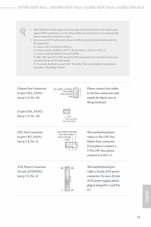
Chassis Fan Connector(4-pin CHA_FAN1)(see p.7, 8, No. 19)
(3-pin CHA_FAN2)(see p.7, 8, No. 16)
Please connect fan cables to the fan connectors and match the black wire to the ground pin.
CPU Fan Connector(4-pin CPU_FAN1)(see p.7, 8, No. 2)
This motherboard pro-vides a 4-Pin CPU fan (Quiet Fan) connector. If you plan to connect a 3-Pin CPU fan, please connect it to Pin 1-3.
ATX Power Connector(24-pin ATXPWR1)(see p.7, 8, No. 4)
This motherboard pro-vides a 24-pin ATX power connector. To use a 20-pin ATX power supply, please plug it along Pin 1 and Pin 13.
FAN_VOLTAGEGND
FAN_SPEEDFAN_SPEED_CONTROL
1234
GND
FAN_VOLTAGECHA_FAN_SPEED
FAN_VOLTAGEGND
CPU_FAN_SPEED
FAN_SPEED_CONTROL
1 2 3 4
12
1
24
13

English
32
ATX 12V Power Connector(4-pin ATX12V1)(see p.7, 8, No. 1)
Please connect an ATX 12V power supply to this connector.
Serial Port Header(9-pin COM1)(see p.7, 8, No. 14)
This COM1 header supports a serial port module.
TPM Header(17-pin TPMS1)(see p.7, 8, No. 15)
This connector supports Trusted Platform Module (TPM) system, which can securely store keys, digital certificates, passwords, and data. A TPM system also helps enhance network security, protects digital identities, and ensures platform integrity.
CCTS#1
RRTS#1
DDSR#1
DDTR#1
RRXD1
GND
TTXD1
DDCD#1
1
RRI#1
1
GND
SMB_
DATA
_MAIN
LAD2
LAD1
GND
S_PW
RDWN#
SERIRQ
#
GND
PCICLK
PCIRST
#
LAD3
+3V
LAD0
+3V
SB
GND
FRAME
SMB_
CLK
_MAIN

X370M-HDV R4.0 / AB350M-HDV R4.0 / A320M-HDV R4.0 / A320M-DVS R4.0
33
Engl
ish
2.7 M.2_SSD (NGFF) Module Installation Guide (for X370M-HDV R4.0 / AB350M-HDV R4.0 / A320M-HDV R4.0 only)The M.2, also known as the Next Generation Form Factor (NGFF), is a small size and versatile card edge connector that aims to replace mPCIe and mSATA. The Ultra M.2 Socket (M2_1) supports SATA3 6.0 Gb/s module and M.2 PCI Express module up to Gen3x4 (32 Gb/s) (with Summit Ridge, Raven Ridge and Pinnacle Ridge) or Gen3 x2 (16 Gb/s) (with A-Series APU and Athlon 2xxGE series APU).
Installing the M.2_SSD (NGFF) Module
Step 1
Prepare a M.2_SSD (NGFF) module and the screw.
2
1
3
ABC
Step 2
Depending on the PCB type and length of your M.2_SSD (NGFF) module, find the corresponding nut location to be used.
No. 1 2 3
Nut Location A B C
PCB Length 4.2cm 6cm 8cm
Module Type Type 2242 Type2260 Type 2280

English
34
ABC
Step 3
Move the standoff based on the module type and length. The standoff is placed at the nut location D by default. Skip Step 3 and 4 and go straight to Step 5 if you are going to use the default nut. Otherwise, release the standoff by hand.
ABC
Step 4
Peel off the yellow protective film on the nut to be used. Hand tighten the standoff into the desired nut location on the motherboard.
Step 5
Align and gently insert the M.2 (NGFF) SSD module into the M.2 slot. Please be aware that the M.2 (NGFF) SSD module only fits in one orientation.
ABC
ABC 20o

X370M-HDV R4.0 / AB350M-HDV R4.0 / A320M-HDV R4.0 / A320M-DVS R4.0
35
Engl
ish
NUT1NUT2C
Step 6
Tighten the screw with a screwdriver to secure the module into place. Please do not overtighten the screw as this might damage the module.

English
36
M.2_SSD (NGFF) Module Support List
For the latest updates of M.2_SSD (NFGG) module support list, please visit our website for details: http://www.asrock.com
Vendor Interface P/NSanDisk PCIe SanDisk-SD6PP4M-128G( Gen2 x2)Intel PCIe INTEL 6000P-SSDPEKKF256G7 (nvme)Intel PCIe INTEL 6000P-SSDPEKKF512G7 (nvme)Kingston PCIe Kingston SHPM2280P2 / 240G (Gen2 x4)Samsung PCIe Samsung XP941-MZHPU512HCGL(Gen2x4)ADATA SATA ADATA - AXNS381E-128GM-BCrucial SATA Crucial-CT240M500SSD4-240GBezlink SATA ezlink P51B-80-120GBIntel SATA INTEL 540S-SSDSCKKW240H6-240GBKingston SATA Kingston SM2280S3G2/120G - Win8.1Kingston SATA Kingston-RBU-SNS8400S3 / 180GDLITEON SATA LITEON LJH-256V2G-256GB (2260)PLEXTOR SATA PLEXTOR PX-128M6G-2260-128GBPLEXTOR SATA PLEXTOR PX-128M7VG-128GBSanDisk SATA SanDisk X400-SD8SN8U-128GSanDisk SATA Sandisk Z400s-SD8SNAT-128G-1122SanDisk SATA SanDisk-SD6SN1M-128GTranscend SATA Transcend TS256GMTS800-256GBV-Color SATA V-Color 120GV-Color SATA V-Color 240GWD SATA WD GREEN WDS240G1G0B-00RC30

X370M-HDV R4.0 / AB350M-HDV R4.0 / A320M-HDV R4.0 / A320M-DVS R4.0
37
Engl
ish
Chapter 3 Software and Utilities Operation 3.1 Installing DriversThe Support CD that comes with the motherboard contains necessary drivers and useful utilities that enhance the motherboard’s features.
Running The Support CDTo begin using the support CD, insert the CD into your CD-ROM drive. The CD automatically displays the Main Menu if “AUTORUN” is enabled in your computer. If the Main Menu does not appear automatically, locate and double click on the file “ASRSETUP.EXE” in the Support CD to display the menu.
Drivers MenuThe drivers compatible to your system will be auto-detected and listed on the support CD driver page. Please click Install All or follow the order from top to bottom to install those required drivers. Therefore, the drivers you install can work properly.
Utilities MenuThe Utilities Menu shows the application software that the motherboard supports. Click on a specific item then follow the installation wizard to install it.

English
38
3.2 A-TuningA-Tuning is ASRock’s multi purpose software suite with a new interface, more new features and improved utilities.
3.2.1 Installing A-Tuning
A-Tuning can be downloaded from ASRock Live Update & APP Shop. After the installation, you will find the icon “A-Tuning“ on your desktop. Double-click the “A-Tuning“ icon, A-Tuning main menu will pop up.
3.2.2 Using A-Tuning
There are five sections in A-Tuning main menu: Operation Mode, OC Tweaker, System Info, FAN-Tastic Tuning and Settings.
Operation ModeChoose an operation mode for your computer.

X370M-HDV R4.0 / AB350M-HDV R4.0 / A320M-HDV R4.0 / A320M-DVS R4.0
39
Engl
ish
OC TweakerConfigurations for overclocking the system.
System InfoView information about the system. *The System Browser tab may not appear for certain models.
English
40
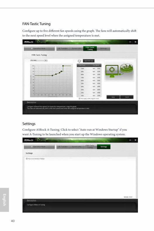
FAN-Tastic Tuning
Configure up to five different fan speeds using the graph. The fans will automatically shift to the next speed level when the assigned temperature is met.
SettingsConfigure ASRock A-Tuning. Click to select "Auto run at Windows Startup" if you want A-Tuning to be launched when you start up the Windows operating system.

X370M-HDV R4.0 / AB350M-HDV R4.0 / A320M-HDV R4.0 / A320M-DVS R4.0
41
Engl
ish
3.3 ASRock Live Update & APP Shop
The ASRock Live Update & APP Shop is an online store for purchasing and downloading software applications for your ASRock computer. You can quickly and easily install various apps and support utilities.With ASRock Live Update & APP Shop, you can optimize your system and keep your motherboard up to date simply with a few clicks.
Double-click on your desktop to access ASRock Live Update & APP Shop utility.
*You need to be connected to the Internet to download apps from the ASRock Live Update & APP Shop.
3.3.1 UI Overview
Category Panel: The category panel contains several category tabs or buttons that when selected the information panel below displays the relative information.
Information Panel: The information panel in the center displays data about the currently selected category and allows users to perform job-related tasks.
Hot News: The hot news section displays the various latest news. Click on the image to visit the website of the selected news and know more.
Information Panel
Hot NewsCategory Panel
English
42
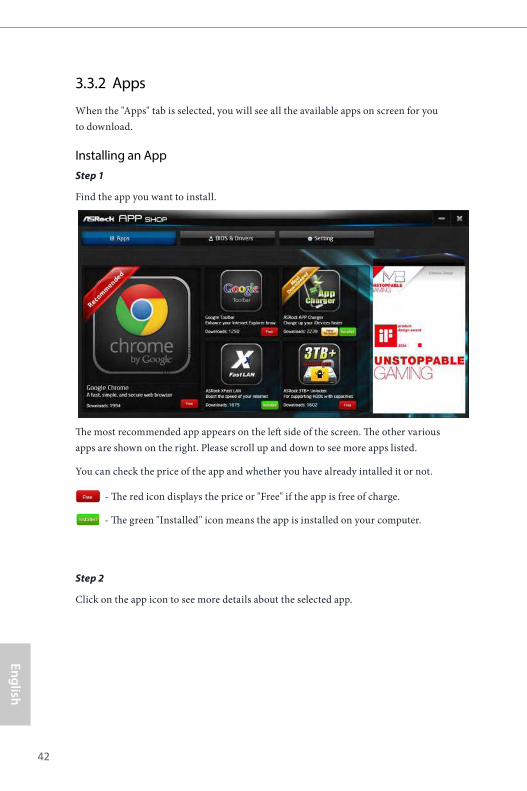
3.3.2 Apps
When the "Apps" tab is selected, you will see all the available apps on screen for you to download.
Installing an AppStep 1
Find the app you want to install.
The most recommended app appears on the left side of the screen. The other various apps are shown on the right. Please scroll up and down to see more apps listed.
You can check the price of the app and whether you have already intalled it or not.
- The red icon displays the price or "Free" if the app is free of charge.
- The green "Installed" icon means the app is installed on your computer.
Step 2
Click on the app icon to see more details about the selected app.
X370M-HDV R4.0 / AB350M-HDV R4.0 / A320M-HDV R4.0 / A320M-DVS R4.0
43
Engl
ish
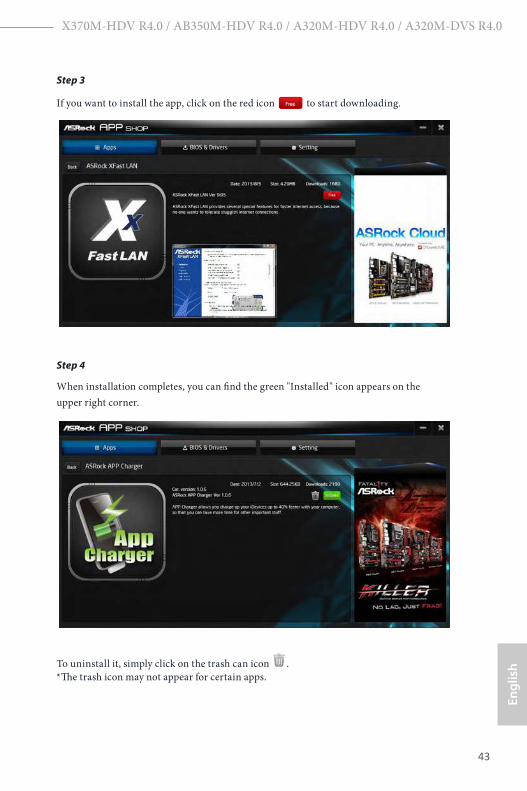
Step 3
If you want to install the app, click on the red icon to start downloading.
Step 4
When installation completes, you can find the green "Installed" icon appears on the upper right corner.
To uninstall it, simply click on the trash can icon . *The trash icon may not appear for certain apps.

English
44
Upgrading an AppYou can only upgrade the apps you have already installed. When there is an available new version for your app, you will find the mark of "New Version" appears below the installed app icon.
Step 1
Click on the app icon to see more details.
Step 2
Click on the yellow icon to start upgrading.
X370M-HDV R4.0 / AB350M-HDV R4.0 / A320M-HDV R4.0 / A320M-DVS R4.0
45
Engl
ish
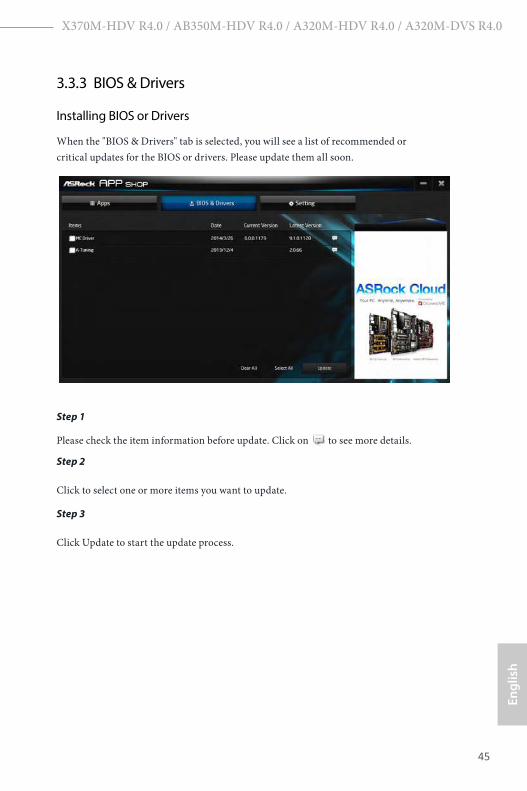
3.3.3 BIOS & Drivers
Installing BIOS or Drivers
When the "BIOS & Drivers" tab is selected, you will see a list of recommended or critical updates for the BIOS or drivers. Please update them all soon.
Step 1
Please check the item information before update. Click on to see more details.
Step 2
Click to select one or more items you want to update.
Step 3
Click Update to start the update process.

English
46
3.3.4 Setting
In the "Setting" page, you can change the language, select the server location, and determine if you want to automatically run the ASRock Live Update & APP Shop on Windows startup.
X370M-HDV R4.0 / AB350M-HDV R4.0 / A320M-HDV R4.0 / A320M-DVS R4.0
47
Engl
ish
Chapter 4 UEFI SETUP UTILITY
4.1 IntroductionThis section explains how to use the UEFI SETUP UTILITY to configure your system. You may run the UEFI SETUP UTILITY by pressing <F2> or <Del> right after you power on the computer, otherwise, the Power-On-Self-Test (POST) will continue with its test routines. If you wish to enter the UEFI SETUP UTILITY after POST, restart the system by pressing <Ctl> + <Alt> + <Delete>, or by pressing the reset button on the system chassis. You may also restart by turning the system off and then back on.
4.1.1 UEFI Menu Bar
The top of the screen has a menu bar with the following selections:
Main For setting system time/date information
OC Tweaker For overclocking configurations
Advanced For advanced system configurations
Tool Useful tools
H/W Monitor Displays current hardware status
Boot For configuring boot settings and boot priority
Security For security settings
Exit Exit the current screen or the UEFI Setup Utility
Because the UEFI software is constantly being updated, the following UEFI setup screens and descriptions are for reference purpose only, and they may not exactly match what you see on your screen.

English
48
4.1.2 Navigation KeysUse < > key or < > key to choose among the selections on the menu bar, and use < > key or < > key to move the cursor up or down to select items, then press <Enter> to get into the sub screen. You can also use the mouse to click your required item.
Please check the following table for the descriptions of each navigation key.
Navigation Key(s) Description
+ / - To change option for the selected items
<Tab> Switch to next function
<PGUP> Go to the previous page
<PGDN> Go to the next page
<HOME> Go to the top of the screen
<END> Go to the bottom of the screen
<F1> To display the General Help Screen
<F7> Discard changes and exit the SETUP UTILITY
<F9> Load optimal default values for all the settings
<F10> Save changes and exit the SETUP UTILITY
<F12> Print screen
<ESC> Jump to the Exit Screen or exit the current screen

X370M-HDV R4.0 / AB350M-HDV R4.0 / A320M-HDV R4.0 / A320M-DVS R4.0
49
Engl
ish
4.2 Main ScreenWhen you enter the UEFI SETUP UTILITY, the Main screen will appear and display the system overview.
English
50
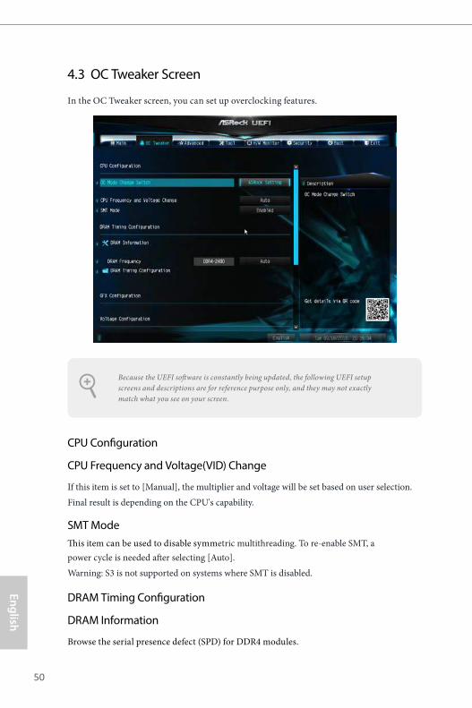
4.3 OC Tweaker Screen
In the OC Tweaker screen, you can set up overclocking features.
CPU Configuration
CPU Frequency and Voltage(VID) Change
If this item is set to [Manual], the multiplier and voltage will be set based on user selection. Final result is depending on the CPU's capability.
SMT ModeThis item can be used to disable symmetric multithreading. To re-enable SMT, a power cycle is needed after selecting [Auto]. Warning: S3 is not supported on systems where SMT is disabled.
DRAM Timing Configuration
DRAM Information
Browse the serial presence defect (SPD) for DDR4 modules.
Because the UEFI software is constantly being updated, the following UEFI setup screens and descriptions are for reference purpose only, and they may not exactly match what you see on your screen.
X370M-HDV R4.0 / AB350M-HDV R4.0 / A320M-HDV R4.0 / A320M-DVS R4.0
51
Engl
ish
DRAM FrequencyIf [Auto] is selected, the motherboard will detect the memory module(s) inserted and assign the appropriate frequency automatically.
GFX Clock FrequencyThis item allows you to alter the frequency for the GPU.
GFX Core Voltage This item allows you to alter the voltage for the GPU.
Voltage Configuration
CPU SOC Voltage (for X370M-HDV R4.0 / AB350M-HDV R4.0 only)
Configure the voltage for the CPU SOC supply level.
DRAM VoltageUse this to select DRAM Voltage. The default value is [Auto].
Save User DefaultType a profile name and press enter to save your settings as user default.
Load User DefaultLoad previously saved user defaults.
Save User UEFI Setup Profile to DiskSave current UEFI settings as an user default profile to disk.
Load User UEFI Setup Profile to DiskLoad previously saved user defaults from the disk.

English
52
4.4 Advanced Screen
In this section, you may set the configurations for the following items: CPU Configuration, North Bridge Configuration, South Bridge Configuration, Storage-Configuration, Super IO Configuration, ACPI Configuration, Trusted Computing, AMD CBS and AMD PBS.
UEFI Configuration
Active Page on Entry
Select the default page when entering the UEFI setup utility.
Full HD UEFIWhen [Auto] is selected, the resolution will be set to 1920 x 1080 if the monitor supports Full HD resolution. If the monitor does not support Full HD resolution, then the resolution will be set to 1024 x 768. When [Disable] is selected, the resolution will be set to 1024 x 768 directly.
Setting wrong values in this section may cause the system to malfunction.

X370M-HDV R4.0 / AB350M-HDV R4.0 / A320M-HDV R4.0 / A320M-DVS R4.0
53
Engl
ish
4.4.1 CPU Configuration
Cool 'n' Quiet
Use this item to enable or disable AMD’s Cool ‘n’ QuietTM technology. The default value is [Enabled]. Configuration options: [Enabled] and [Disabled]. If you install Windows® OS and want to enable this function, please set this item to [Enabled]. Please note that enabling this function may reduce CPU voltage and memory frequency, and lead to system stability or compatibility issue with some memory modules or power supplies. Please set this item to [Disable] if above issue occurs.
AMD fTPM SwitchUse this to enable or disable AMD CPU fTPM.
SVM ModeWhen this option is set to [Enabled], a VMM (Virtual Machine Architecture) can utilize the additional hardware capabilities provided by AMD-V. The default value is [Enabled]. Configuration options: [Enabled] and [Disabled].

English
54
4.4.2 North Bridge Configuration
SR-IOV Support
Enable/disable the SR-IOV (Single Root IO Virtualization Support) if the system has SR-IOV capable PCIe devices.

X370M-HDV R4.0 / AB350M-HDV R4.0 / A320M-HDV R4.0 / A320M-DVS R4.0
55
Engl
ish
4.4.3 South Bridge Configuration
Onboard HD AudioEnable/disable onboard HD audio. Set to Auto to enable onboard HD audio and automatically disable it when a sound card is installed.
Front Panel
Enable/disable front panel HD audio.
Deep Sleep
Configure deep sleep mode for power saving when the computer is shut down.
Restore on AC/Power LossSelect the power state after a power failure. If [Power Off] is selected, the power will remain off when the power recovers. If [Power On] is selected, the system will start to boot up when the power recovers.
English
56
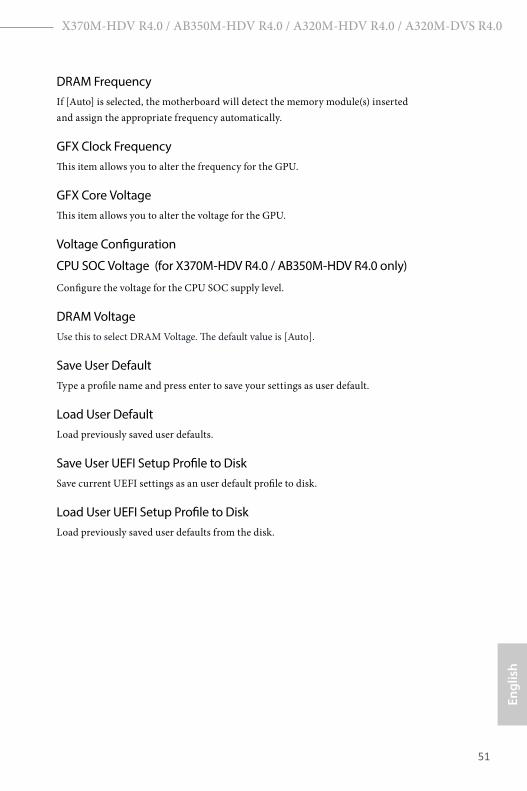
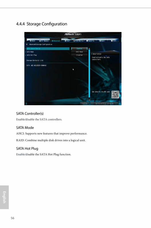
4.4.4 Storage Configuration
SATA Controller(s)Enable/disable the SATA controllers.
SATA ModeAHCI: Supports new features that improve performance.
RAID: Combine multiple disk drives into a logical unit.
SATA Hot PlugEnable/disable the SATA Hot Plug function.
X370M-HDV R4.0 / AB350M-HDV R4.0 / A320M-HDV R4.0 / A320M-DVS R4.0
57
Engl
ish
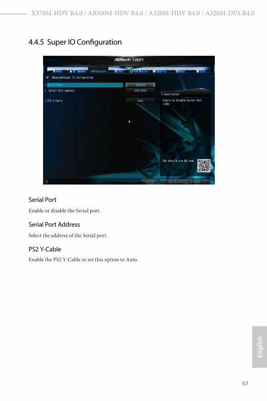
4.4.5 Super IO Configuration
Serial Port
Enable or disable the Serial port.
Serial Port Address
Select the address of the Serial port.
PS2 Y-CableEnable the PS2 Y-Cable or set this option to Auto.

English
58
4.4.6 ACPI Configuration
Suspend to RAMIt is recommended to select auto for ACPI S3 power saving.
ACPI HPET TableEnable the High Precision Event Timer for better performance and to pass WHQL tests.
PS/2 Keyboard Power OnAllow the system to be waked up by a PS/2 Keyboard.
PCIE Devices Power OnAllow the system to be waked up by a PCIE device and enable wake on LAN.
RTC Alarm Power OnAllow the system to be waked up by the real time clock alarm. Set it to By OS to let it be handled by your operating system.
X370M-HDV R4.0 / AB350M-HDV R4.0 / A320M-HDV R4.0 / A320M-DVS R4.0
59
Engl
ish
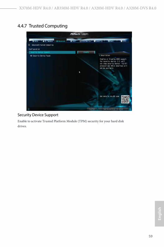
4.4.7 Trusted Computing
Security Device SupportEnable to activate Trusted Platform Module (TPM) security for your hard disk drives.
English
60
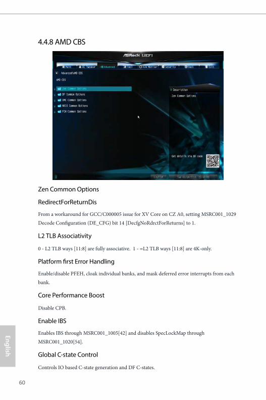
4.4.8 AMD CBS
Zen Common Options
RedirectForReturnDis
From a workaround for GCC/C000005 issue for XV Core on CZ A0, setting MSRC001_1029 Decode Configuration (DE_CFG) bit 14 [DecfgNoRdrctForReturns] to 1.
L2 TLB Associativity
0 - L2 TLB ways [11:8] are fully associative. 1 - =L2 TLB ways [11:8] are 4K-only.
Platform first Error Handling
Enable/disable PFEH, cloak individual banks, and mask deferred error interrupts from each bank.
Core Performance Boost
Disable CPB.
Enable IBS
Enables IBS through MSRC001_1005[42] and disables SpecLockMap through MSRC001_1020[54].
Global C-state Control
Controls IO based C-state generation and DF C-states.

X370M-HDV R4.0 / AB350M-HDV R4.0 / A320M-HDV R4.0 / A320M-DVS R4.0
61
Engl
ish
Opcache Control
Enables or disables the Opcache.
OC Mode
OC1 - 16 cores/3.6GHz on 1.3375V OC2 - 8 cores/3.7GHz on 1.369V OC3 - 4 cores/3.75GHz on 1.374V\nMax Stress - 16 cores/3.8GHz on 1.400V
SEV-ES ASID Space Limit
SEV VMs using ASIDs below the SEV-ES ASID Space Limit must enable the SEV-ES feature. The valid values for this field are from 0x1 (1) - 0x10 (16).
Core/Thread Enablement
Downcore control
Sets the number of cores to be used. Once this option has been used to remove any cores, a POWER CYCLE is required in order for future selections to take effect.
SMTEN
This item can be used to disable symmetric multithreading. To re-enable SMT, a POWER CYCLE is needed after selecting the 'Auto' option. Warning: S3 is NOT SUPPORTED on systems where SMT is disabled.
Streaming Stores Control
Enables or disables the streaming stores functionality.
DF Common Options
DRAM scrub time
Provide a value that is the number of hours to scrub memory.
Redirect scrubber control
Control DF::RedirScrubCtrl[EnRedirScrub]
Disable DF sync flood propagation
Control DF::PIEConfig[DisSyncFloodProp].
Freeze DF module queues on error
Controls DF::PIEConfig[DisImmSyncFloodOnFatalError] Disabling this option sets DF:PIEConfig[DisImmSyncFloodOnFatalError].
English
62
GMI encryption control
GMI encryption control
Control GMI link encryption
xGMI encryption control
Control xGMI link encryption
CC6 memory region encryption
Control whether or not the CC6 save/restore memory is encrypted
Location of private memory regions
Controls whether or not the private memory regions (PSP, SMU and CC6) are at the top of DRAM or distributed. Note that distributed requires memory on all dies. Note that it will always be at the top of DRAM if some dies don't have memory regardless of this option's setting.
System probe filter
Controls whether or not the probe filter is enabled. Has no effect on parts where the probe filter is fuse disabled.
Memory interleaving
Controls fabric level memory interleaving (AUTO, none, channel, die, socket). Note that channel, die, and socket has requirements on memory populations and it will be ignored if the memory doesn't support the selected option.
Memory interleaving size
Controls the memory interleaving size. The valid values are AUTO, 256 bytes, 512 bytes, 1 Kbytes or 2Kbytes. This determines the starting address of the interleave (bit 8, 9, 10 or 11).
Channel interleaving hash
Controls whether or not the address bits are hashed during channel interleave mode. This field should not be used unless the interleaving is set to channel and the interleaving size is 256 or 512 bytes.
Memory Clear
When this feature is disabled, BIOS does not implement MemClear after memory training (only if non-ECC DIMMs are used).

X370M-HDV R4.0 / AB350M-HDV R4.0 / A320M-HDV R4.0 / A320M-DVS R4.0
63
Engl
ish
UMC Common Options
DDR4 Common Options
DRAM Controller Configuration
DRAM Controller Configuration
DRAM Power Options
Cmd2T
Select between 1T and 2T mode on ADDR/CMD
Gear Down Mode
Configure the Gear Down Mode.
CAD Bus Configuration
CAD Bus Timing User Controls
Setup time on CAD bus signals to Auto or Manual
CAD Bus Drive Strength User Controls
Drive Strength on CAD bus signals to Auto or Manual
Data Bus Configuration
Data Bus Configuration User Controls
Specify the mode for drive strength to Auto or Manual
Common RAS
Data Poisoning
Enable/disable data poisoning: UMC_CH::EccCtrl[UcFatalEn] UMC_CH::EccCtrl[WrEccEn] Should be enabled/disabled together.
Security
TSME
Transparent SME: AddrTweakEn = 1; ForceEncrEn =1; DataEncrEn = 0
Data Scramble
Data scrambling: DataScrambleEn

English
64
DRAM Memory Mapping
Chipselect Interleaving
Interleave memory blocks across the DRAM chip selects for node 0.
BankGroupSwap
Configure the BankGroupSwap.
BankGroupSwapAlt
Configure BankGroupSwapAlt.
Address Hash Bank
Configure the bank address hashing.
Address Hash CS
Configure the CS address hashing.
NVDIMM
Memory MBIST
MBIST Enable
Configure the Memory MBIST.
MBIST SubType Test
Select MBIST Subtest - Single Chipselect, Multi Chipselect, Address Line Test or execute All test
MBIST Aggressors
Enable or disable MBIST Aggressor test.
MBIST Per Bit Slave Die Reporting
Enable or disable MBIST per bit slave die result report.
NBIO Common Options
NB Configuration
IOMMU
Use this to enable or disable IOMMU. The default value of this feature is [Disabled].

X370M-HDV R4.0 / AB350M-HDV R4.0 / A320M-HDV R4.0 / A320M-DVS R4.0
65
Engl
ish
Determinism Slider
[Auto]
Use default performance determinism settings
cTDP Control
[Auto]
Use the fused cTDP.
[Manual]
User can set customized cTDP.
Fan Control
[Auto]
Use the default fan controller settings.
[Manual]
User can set customized fan controller settings.
PSI
Disable PSI.
ACS Enable
Enable ACS.
PCIe ARI Support
Enables Alternative Routing-ID Interpretation
CLDO_VDDP Control
[Manual]
If this option is selected, user can set customized CLDO_VDDP voltage.
HD Audio Enable
Enable HD Audio.
FCH Common Options
SATA Configuration Options
English
66
SATA Controller
Disable or enable OnChip SATA controller
Sata RAS Support
Disable or enable Sata RAS Support
Sata Disabled AHCI Prefetch Function
Configure the Sata Disabled AHCI Prefetch function.
Aggresive SATA Device Sleep Port 0
Configure the Aggresive SATA Device Sleep Port 0.
Aggresive SATA Device Sleep Port 1
Configure the Aggresive SATA Device Sleep Port 1.
USB Configuration Options
XHCI controller enable
Configure the USB3 controller.
SD (Secure Digital) Options
SD Configuration Mode
Select SD Mode.
Ac Power Loss Options
Select Ac Loss Control Method.
I2C Configuration Options
Uart Configuration Options
ESPI Configuration Options
XGBE Configuration Options
eMMC Options
NTB Common Options
DRAM Memory Mapping

X370M-HDV R4.0 / AB350M-HDV R4.0 / A320M-HDV R4.0 / A320M-DVS R4.0
67
Engl
ish
Chipselect Interleaving
Interleave memory blocks across the DRAM chip selects for node 0.
BankGroupSwap
Configure the BankGroupSwap.
BankGroupSwapAlt
Configure the BankGroupSwapAlt.
Address Hash Bank
Configure the bank address hashing.
Address Hash CS
Configure the CS address hashing.
NVDIMM
Memory MBIST
MBIST Enable
Configure the Memory MBIST.
MBIST SubType Test
Select MBIST Subtest - Single Chipselect, Multi Chipselect, Address Line Test or execute all test.
MBIST Aggressors
Configure the MBIST Aggressor test.
MBIST Per Bit Slave Die Reporting
Configure the MBIST per bit slave die result report.
English
68
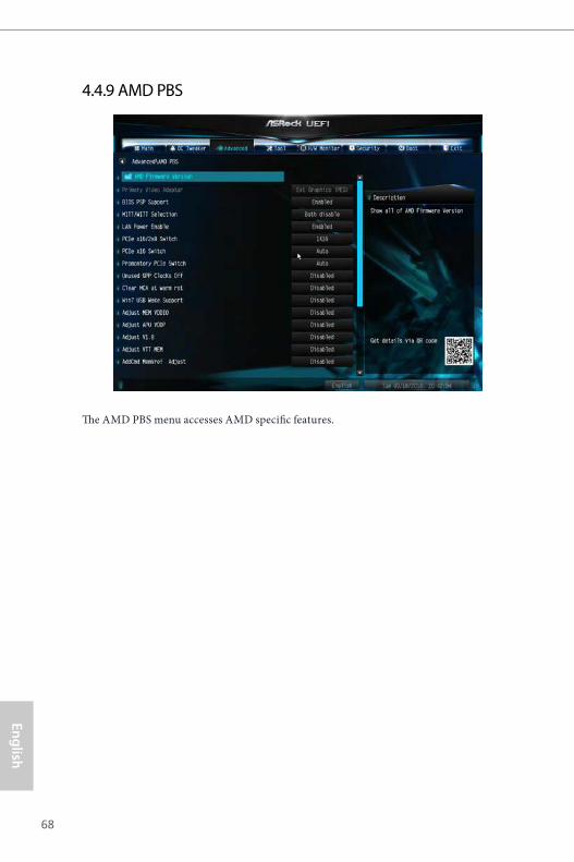
4.4.9 AMD PBS
The AMD PBS menu accesses AMD specific features.
X370M-HDV R4.0 / AB350M-HDV R4.0 / A320M-HDV R4.0 / A320M-DVS R4.0
69
Engl
ish
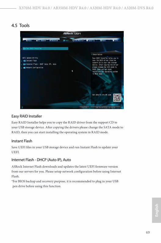
4.5 Tools
Easy RAID InstallerEasy RAID Installer helps you to copy the RAID driver from the support CD to your USB storage device. After copying the drivers please change the SATA mode to RAID, then you can start installing the operating system in RAID mode.
Instant FlashSave UEFI files in your USB storage device and run Instant Flash to update your UEFI.
Internet Flash - DHCP (Auto IP), Auto
ASRock Internet Flash downloads and updates the latest UEFI firmware version from our servers for you. Please setup network configuration before using Internet Flash. *For BIOS backup and recovery purpose, it is recommended to plug in your USB pen drive before using this function.

English
70
Network ConfigurationUse this to configure internet connection settings for Internet Flash.
Internet SettingEnable or disable sound effects in the setup utility.
UEFI Download ServerSelect a server to download the UEFI firmware.
X370M-HDV R4.0 / AB350M-HDV R4.0 / A320M-HDV R4.0 / A320M-DVS R4.0
71
Engl
ish
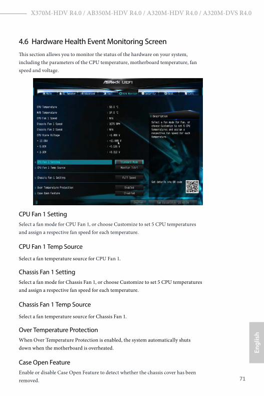
4.6 Hardware Health Event Monitoring ScreenThis section allows you to monitor the status of the hardware on your system, including the parameters of the CPU temperature, motherboard temperature, fan speed and voltage.
CPU Fan 1 SettingSelect a fan mode for CPU Fan 1, or choose Customize to set 5 CPU temperatures and assign a respective fan speed for each temperature.
CPU Fan 1 Temp Source
Select a fan temperature source for CPU Fan 1.
Chassis Fan 1 SettingSelect a fan mode for Chassis Fan 1, or choose Customize to set 5 CPU temperatures and assign a respective fan speed for each temperature.
Chassis Fan 1 Temp Source
Select a fan temperature source for Chassis Fan 1.
Over Temperature ProtectionWhen Over Temperature Protection is enabled, the system automatically shuts down when the motherboard is overheated.
Case Open FeatureEnable or disable Case Open Feature to detect whether the chassis cover has been removed.

English
72
4.7 Security ScreenIn this section you may set or change the supervisor/user password for the system. You may also clear the user password.
Supervisor PasswordSet or change the password for the administrator account. Only the administrator has authority to change the settings in the UEFI Setup Utility. Leave it blank and press enter to remove the password.
User PasswordSet or change the password for the user account. Users are unable to change the settings in the UEFI Setup Utility. Leave it blank and press enter to remove the password.
Secure BootEnable to support Secure Boot.

X370M-HDV R4.0 / AB350M-HDV R4.0 / A320M-HDV R4.0 / A320M-DVS R4.0
73
Engl
ish
4.8 Boot ScreenThis section displays the available devices on your system for you to configure the boot settings and the boot priority.
Fast BootFast Boot minimizes your computer's boot time. In fast mode you may not boot from an USB storage device.
Boot From Onboard LANAllow the system to be waked up by the onboard LAN.
Setup Prompt Timeout
Configure the number of seconds to wait for the setup hot key.
Bootup Num-LockSelect whether Num Lock should be turned on or off when the system boots up.
Boot Beep
Select whether the Boot Beep should be turned on or off when the system boots up. Please note that a buzzer is needed.
Full Screen Logo
Enable to display the boot logo or disable to show normal POST messages.

English
74
AddOn ROM Display
Enable AddOn ROM Display to see the AddOn ROM messages or configure the AddOn ROM if you've enabled Full Screen Logo. Disable for faster boot speed.
Above 4G Decoding
Enable/disable the 64-bit capable devices to be decoded in above 4G address space.
CSM (Compatibility Support Module)
CSM Enable to launch the Compatibility Support Module. Please do not disable unless you’re running a WHCK test.
Launch PXE OpROM Policy Select UEFI only to run those that support UEFI option ROM only. Select Legacy only to run those that support legacy option ROM only. Select Do not launch to not execute both legacy and UEFI option ROM.
Launch Storage OpROM PolicySelect UEFI only to run those that support UEFI option ROM only. Select Legacy only to run those that support legacy option ROM only. Select Do not launch to not execute both legacy and UEFI option ROM.

X370M-HDV R4.0 / AB350M-HDV R4.0 / A320M-HDV R4.0 / A320M-DVS R4.0
75
Engl
ish
4.9 Exit Screen
Save Changes and ExitWhen you select this option the following message, “Save configuration changes and exit setup?” will pop out. Select [OK] to save changes and exit the UEFI SETUP UTILITY.
Discard Changes and ExitWhen you select this option the following message, “Discard changes and exit setup?” will pop out. Select [OK] to exit the UEFI SETUP UTILITY without saving any changes.
Discard ChangesWhen you select this option the following message, “Discard changes?” will pop out. Select [OK] to discard all changes.
Load UEFI DefaultsLoad UEFI default values for all options. The F9 key can be used for this operation.
Launch EFI Shell from filesystem deviceCopy shellx64.efi to the root directory to launch EFI Shell.

Contact Information
If you need to contact ASRock or want to know more about ASRock, you’re welcome to visit ASRock’s website at http://www.asrock.com; or you may contact your dealer for further information. For technical questions, please submit a support request form at http://www.asrock.com/support/tsd.asp
ASRock Incorporation2F., No.37, Sec. 2, Jhongyang S. Rd., Beitou District,
Taipei City 112, Taiwan (R.O.C.)
ASRock EUROPE B.V.Bijsterhuizen 11-11
6546 AR Nijmegen
The Netherlands
Phone: +31-24-345-44-33
Fax: +31-24-345-44-38
ASRock America, Inc.13848 Magnolia Ave, Chino, CA91710
U.S.A.
Phone: +1-909-590-8308
Fax: +1-909-590-1026

DECLARATION OF CONFORMITY
Per FCC Part 2 Section 2.1077(a)
Responsible Party Name: ASRock Incorporation
Address: 13848 Magnolia Ave, Chino, CA91710
+1-909-590-8308/+1-909-590-1026
Phone/Fax No:
hereby declares that the product
Product Name : Motherboard
Model Number :
Conforms to the following speci�cations:
FCC Part 15, Subpart B, Unintentional Radiators
Supplementary Information:
�is device complies with part 15 of the FCC Rules. Operation is subject to the following two conditions: (1) �is device may not cause harmful interference, and (2) this device must accept any interference received, including interference that may cause undesired operation. Representative Person’s Name: James
Signature :
Date : May 12, 2017
X370M-HDV R4.0 / AB350M-HDV R4.0 / A320M-HDV R4.0 / A320M-DVS R4.0

EU Declaration of Conformity For the following equipment:
Motherboard(Product Name)
X370M-HDV R4.0 / AB350M-HDV R4.0 / A320M-HDV R4.0 / A320M-DVS R4.0 / ASRock
(Model Designation / Trade Name)
ASRock Incorporation(Manufacturer Name)
2F., No.37, Sec. 2, Jhongyang S. Rd., Beitou District, Taipei City 112, Taiwan (R.O.C.)(Manufacturer Address)
ASRock EUROPE B.V.(Company Name)
Bijsterhuizen 1111 6546 AR Nijmegen The Netherlands(Company Address)
Person responsible for making this declaration:
(Name, Surname)A.V.P(Position / Title)October 26, 2018(Date)
P/N: 15G062129000AK V1.0
EMC —Directive 2014/30/EU (from April 20th, 2016) ☐ EN 55022:2010/AC:2011 Class B EN 55024:2010/A1:2015
EN 55032:2012+AC:2013 Class B EN 61000-3-3:2013 EN 61000-3-2:2014
LVD —Directive 2014/35/EU (from April 20th, 2016) EN 60950-1 : 2011+ A2: 2013 ☐☐ EN 60950-1 : 2006/A12: 2011
RoHS — Directive 2011/65/EU CE marking
(EU conformity marking)
☐