vertex 2002, kailua-kona 7.11.2002tobias stockmanns, universität bonn1 serial powering of pixel...
Post on 18-Dec-2015
216 views
TRANSCRIPT

Vertex 2002, Kailua-Kona 7.11.2002 Tobias Stockmanns, Universität Bonn 1
Serial Powering of Pixel Modules
T. Stockmanns, P. Fischer, O. Runolfsson and N. Wermes
Vertex 2002, Kailua-Kona 7.11.2002 Tobias Stockmanns, Universität Bonn 2
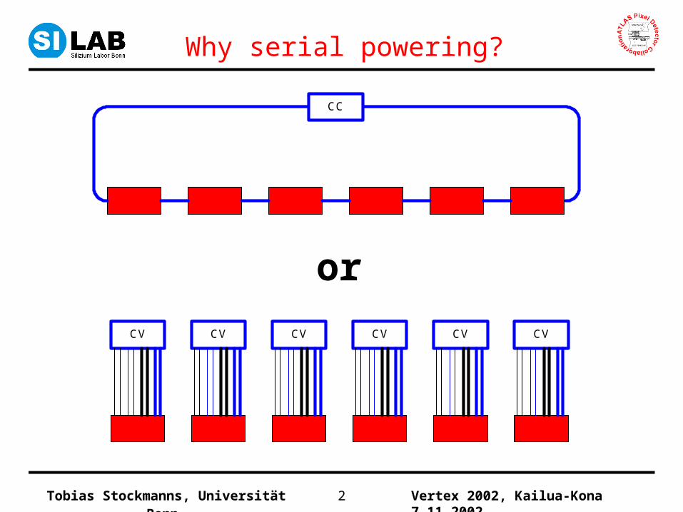
Why serial powering?
CC
CV CV CV CV CV CV
or

Vertex 2002, Kailua-Kona 7.11.2002 Tobias Stockmanns, Universität Bonn 3
Power consumption
• Every ATLAS - pixel module needs:
– 2 supply voltages:
Name Voltage Current Power
VDDA 1.7 V 970 – 1290 mA 1650 – 2200 mW
VDD 2 V 500 – 800 mA 1000 – 1320 mW
Sum 1.5 - 2 A
Total detector
(1750 modules)
2 V 3500 A
– 1 HV bias connection– 3 ground lines
6power linesper module

Vertex 2002, Kailua-Kona 7.11.2002 Tobias Stockmanns, Universität Bonn 4
Cable
Powersupply
PP 3 PP 2
PP 1PP 0
120 m
20 m
9 m
2,8 m
0,5 V
1 V
0,5 V
0,55 V
< 0,5 m
Pixel detector
Modules
3V
Add. 1 V
cable costs cable size
cable mass
Total distance: 152 mMaximum voltage drop: 6.5 VOptimum: No cables at all

Vertex 2002, Kailua-Kona 7.11.2002 Tobias Stockmanns, Universität Bonn 5
16FE FEModule 1
VDDA VDD
Regulator
16FE FEModule 2
VDDA VDD
Regulatorconstant voltagepower supply
constant voltagepower supply
Parallel Powering
• For a stave of 13 modules:
- power + sense lines: 104
- supply voltage: 2 V / 1,7 V
- supply current: 26 A
- power consumption: 47 W
+ voltage drop: 226 W

Vertex 2002, Kailua-Kona 7.11.2002 Tobias Stockmanns, Universität Bonn 6
readout
readout
readout
On chip On chip
16
I0
FE FE
16FE FE
16FE FE
Module 1
Module 2
Module 13
ConstantCurrentPowerSupply
Alternative: Serial Powering
shunt regulator
VDD
linear regulator
VDDA
26 V
24 V
24 V
20 V
2 V
0 V
• For a stave of 13 modules:
- power + sense lines: 2
- supply voltage: 26 V
- supply current: 2 A
- power consumption: 52 W
+ voltage drop: 65 W

Vertex 2002, Kailua-Kona 7.11.2002 Tobias Stockmanns, Universität Bonn 7
Pros and Consof both concepts
Parallel Powering Serial Powering
Pros Cons
• Individual control of each module • Difficult to switch off a single module
• No risk for the full chain • Risk to loose a full chain
• Possible noise crosstalk via power lines
Cons Pros
• low voltage + high current high voltage drop
• high voltage + low current low voltage drop
• high total power of pixel detector • lower power consumption of pixel detector
• one power supply per module • one power supply per chain
• large amount of cables • less amount of cables

Vertex 2002, Kailua-Kona 7.11.2002 Tobias Stockmanns, Universität Bonn 8
Shunt regulators
• 10 shunt regulators built with commercial ICs• All of them operated in series• 2 modified to work with the required voltage• water cooled

Vertex 2002, Kailua-Kona 7.11.2002 Tobias Stockmanns, Universität Bonn 9
Parallel readout of 2 serially powered modules
VME - Crate
PCC
PCC
Module 1
2 A
Module 2
PLL 1 + 2 PixDAQ 1 + 2
Shunt -Regulators
Linear -Regulator

Vertex 2002, Kailua-Kona 7.11.2002 Tobias Stockmanns, Universität Bonn 11
No influence on module performance
Threshold: 4700 e-
Dispersion: 480 e-
Noise: 150e- / 250 e-
Serial powered Parallel powered
Threshold: 4330 e-
Dispersion: 300 e-
Noise: 148 e-

Vertex 2002, Kailua-Kona 7.11.2002 Tobias Stockmanns, Universität Bonn 14
Integration of regulators in newest FE-chip
1,3 1,4 1,5 1,6 1,7 1,8 1,9 2,0 2,1 2,2
1,25
1,30
1,35
1,40
1,45
minimum dropout voltage 0.285V
Linear regulator Iout
= 60mA
Ou
tpu
t vo
ltag
e [V
]Input voltage [V]
0,0 0,5 1,0 1,5 2,0 2,5 3,0-2000
0
2000
4000
6000
8000
10000
12000
14000Shunt regulator
Slope = 1 / 33.4
- 60C
210C
curr
ent
[µA
]
voltage [V]
shunt regulator and linear regulator implemented and tested in the newest radhard version of the FE-chip

Vertex 2002, Kailua-Kona 7.11.2002 Tobias Stockmanns, Universität Bonn 15
Threshold measurement
4 FE-I chips in parallel 1 + 2 chips in series
FEIFEIFEIFEICCCC
FEI
FEI FEI
Threshold: 4680 e-
Dispersion: 100 e-
Noise: 264 e-
Threshold: 4780 e-
Dispersion: 105 e-
Noise: 268 e-

Vertex 2002, Kailua-Kona 7.11.2002 Tobias Stockmanns, Universität Bonn 16
Serial PoweringSensorless Module
• 13 working chips
• 37120 working pixels
typ.Threshold: 4800 e-
Dispersion: 1340 e- 1200 e-
(untuned!)Noise: 214 e- 160 e-
Vertex 2002, Kailua-Kona 7.11.2002 Tobias Stockmanns, Universität Bonn 17
Summary
• Serial Powering of pixel detectors seems to be possible:
– Feasibility of serial powering proven with external regulators
– Regulators implemented into the new radiation hard FE-chips
– Internal regulators tested on single chips and modules
– electrical performance very similar hope that the differences in noise disappear with new version of regulators
• Next steps:
– Using several modules in a series– Measuring the performance of the modules depending on
different situations– Testing possible failure scenarios

Vertex 2002, Kailua-Kona 7.11.2002 Tobias Stockmanns, Universität Bonn 18
„On Module“ – Serial Powering
• On each side of a module the FE-chips are connected in series Current consumption goes down by a factor of 8 with an 8-times higher voltage
• Opposite FE-chips are on the same DC-potential
ConstantCurrent
16 V14 V12 V10 V8 V6 V4 V2 V
16 V14 V12 V10 V8 V6 V4 V2 V

Vertex 2002, Kailua-Kona 7.11.2002 Tobias Stockmanns, Universität Bonn 19
„On Module“ – Serial Powering
• Implementation:
– AC-coupling between FE-chips and MCC necessary
– Special sensor design necessary
• Disadvantage:
– More complicated module design
• Advantages:
– low current consumption
– no risk of loosing a chain of modules
– individual module operation like in parallel powering