vertical farming facility
TRANSCRIPT

a
TOTAL BUILDING DESIGN ENGINEERING
Architectural Engineering Institute, Annual Student Competition
Registration Number: 04-2015
GROWING POWER
VERTICAL FARMING FACILITY
Inte
gra
tion |
Co
nst
ruct
ion
| M
ech
anic
al |
Ele
ctri
cal
| Str
uct
ura
l

04-2015 NARRATIVE | i Flexibility Sustainability Economy Community
TBD ENGINEERING | INTEGRATION
EXECUTIVE SUMMARY Growing Power’s recent success and growth of their nonprofit organization has created a need of a new
vertical farming facility to enhance their mission of providing equal access to healthy, high-quality, safe
and affordable food for people in all communities. The facility will provide space to demonstrate
innovative farming techniques, an area to host large lectures, office space, and a market to sell food
grown on site. In order for the Growing Power facility to be successful, the project goals defined as
flexibility, community, sustainability, and economy, must be achieved through an integrated design
approach, prioritizing efficiency, mutual trust and respect between partners, and an openness to
collaboration. Total Building Design approached and completed the design of the vertical farm with an
integrated process embraced by all team members, which resulted in a quality facility for Growing Power.
INFORMATION EXCHANGE Integration was empowered through an efficient and effective method of information exchange,
intricately mapped though team collaborative planning sessions with the aid of the Last Planner System®.
TBD utilized a co-located space and various methods of digital communication, including virtual
information exchange between different design partners’ modeling software, to create and maintain a
valuable flow of information.
DECISION MAKING PROCESS To ensure all major design decisions benefited the Growing Power organization and their goals, as well as
confirm that the most advantageous decisions were made, a decision matrix was created to analyze the
value added to the project by design solutions. Continuous cost tracking throughout the design phases
enabled cost to influence decisions across all design partners’ scopes, and target values to be shifted from
one Unitformat II section into another.
INTEGRATED DESIGN PACKAGES To create an environment of simultaneous discipline design focus, 5 design packages were identified,
grouping spaces of similar intended use together. The 5 distinct packages were created with synchronized
design by all parties, enabling real time coordination, integration, with clash resolution and system
integration input from all team members concurrently.
BUILDING INFORMATION MODELING Support for an integrated design process was provided by Building Information Modeling (BIM) tools
and processes. The TBD design partners engaged in BIM Project Execution Planning to take full
advantage of the potential added value by identifying BIM goals and clearly explaining the processes
required to achieve those goals and the information exchanges associated with them.
INTEGRATION POINTS The facility developed though an integrated approach took determination, input, and creative problem
solving from all team members, specifically with development of the rainscreen façade system, the unique
greenhouse design and analysis, and the redesign of the gathering space without the visual interruption of
unnecessary columns. Through facilitated, integrated design management and coordination, and value
driven effort, a cost effective facility aligned with Growing Power’s current goals and the potential for
organizational growth, was produced to be turned over to the ownership partners at Growing Power.
04-2015 NARRATIVE | ii Flexibility Sustainability Economy Community
TBD ENGINEERING | INTEGRATION
TABLE OF CONTENTS Executive Summary ....................................................................................................................................... i
Table of Contents .......................................................................................................................................... ii
Project Introduction .................................................................................................................................. 1
Project Goals ............................................................................................................................................. 1
An Integrated Team Environment................................................................................................................. 2
Information Exchange ............................................................................................................................... 2
Collaborative Planning .......................................................................................................................... 2
Co-location ............................................................................................................................................ 4
Face to Face Communication ................................................................................................................ 5
Digital Communication ......................................................................................................................... 5
Decision Making Process .......................................................................................................................... 5
Integrated Design Packages ...................................................................................................................... 6
Building Information Modeling ................................................................................................................ 7
BIM Execution Planning ....................................................................................................................... 7
Design Integration ......................................................................................................................................... 8
Building Context ....................................................................................................................................... 9
Building Enclosure Design ..................................................................................................................... 10
Rainscreen Backup System ................................................................................................................. 10
Moisture Protection and Insulation for any Climate ........................................................................... 10
Architectural Context .......................................................................................................................... 11
Growing Spaces ...................................................................................................................................... 12
Original Design ................................................................................................................................... 12
A More Efficient Growing Space ....................................................................................................... 12
A Flexible Floor Layout ...................................................................................................................... 13
Efficiency Through an Integrated Approach ....................................................................................... 13
Gathering Space ...................................................................................................................................... 14
Original Design ................................................................................................................................... 14
TBD Improvements and Challenges ................................................................................................... 14
Efficiency Through an Integrated Approach ....................................................................................... 15
References ................................................................................................................................................ SD|I
Last Planner System® ............................................................................................................................. SD|II
Integrated Design Packages .................................................................................................................. SD|III
Planning the Implementation of BIM ................................................................................................... SD|IV
04-2015 NARRATIVE | iii Flexibility Sustainability Economy Community
TBD ENGINEERING | INTEGRATION
Defining BIM Information Exchanges .................................................................................................. SD|V
Coordination ......................................................................................................................................... SD|VI
Rainscreen Façade and Glazing ........................................................................................................... SD|VII
Lower Greenhouse Design ................................................................................................................. SD|VIII
Top Greenhouse Redesign .................................................................................................................... SD|IX
Raised Grate Floor ................................................................................................................................. SD|X
Aquaponics ........................................................................................................................................... SD|XI
Gathering Space Design Coordination ................................................................................................. SDX|II
Project Decision Matrix ............................................................................................................................. D1
Design Schedule......................................................................................................................................... D2
Cost Trending Analysis .............................................................................................................................. D3
Basement Floor Plan .................................................................................................................................. D4
Level 1 Floor Plan ...................................................................................................................................... D5
Level 2 Floor Plan ...................................................................................................................................... D6
Level 3 Floor Plan ...................................................................................................................................... D7
Level 4 Floor Plan ...................................................................................................................................... D8
Level 5 Floor Plan ...................................................................................................................................... D9

TBD ENGINEERING | INTEGRATION
04-2015 NARRATIVE | 1 Flexibility Sustainability Economy Community
PROJECT INTRODUCTION Growing Power Inc., a national nonprofit organization, was established in 1993 to support surrounding
communities and the environment they live in by providing affordable, quality food, grown and
distributed with sustainable methods. They aim to better their communities though the education of
sustainable farming techniques with hands on experience, technical aid, and live demonstration. Growing
Power has found great success in hosting a number of projects to grow food, grow minds, and to grow
community. This success has led to a need of a new, sustainable facility to enable Growing Power to
influence more communities while promoting sustainable farming techniques.
The new 52,585 square foot Growing Power facility is to be constructed on a plot of land the nonprofit
currently owns at 5500 West Silver Springs Drive Milwaukee, Wisconsin. The prominent vertical farming
facility embraces four custom designed greenhouses equipped with flexible MEP systems for
demonstrations of farming techniques and the allotment of different growing methods; an open floor
gathering space for presentations and lectures taking advantage of noteworthy structural feats with an
integrated MEP design; and a sustainable, innovative cogeneration heat and power plant providing clean
and affordable energy, all wrapped in a façade that provides Growing Power the flexibility of placing the
facility in any community, in any climate.
PROJECT GOALS To produce a project valuable to the owner, TBD project goals were developed to align with Growing
Power’s vision of inspiring communities to build sustainable food systems that are equitable and
ecologically sound; creating a just world, one food secure community a time. Incorporating those values
with TBD’s own project initiatives, four goals were created and prioritized to be carried through the
entirety of the design and construction phases of the project: flexibility, community, sustainability, and
economy. Prioritizing these goals ensures the development of a project that meets the needs and
expectoration of the owner. The project goals have been defined as:
PROJECT INITIATIVES
Community Strengthen the community outreach by
providing ample space for education and
enabling the surrounding population to
participate in the growing methods used
within the vertical farm.
Economy Provide the best product for the budget
developed by Growing Power while
continuously providing cost savings and
exploring funding expansion.
Flexibility The ability for the facility to be used as a
prototype for other possible sites across
the country, while meeting the changing
needs of Growing Power by providing
options for continuous improvement.
Sustainability Create a facility with a manageable
lifecycle cost aided by the use and
optimization of renewable energy,
renewable resources, and sustainable
practices in design and construction.

TBD ENGINEERING | INTEGRATION
04-2015 NARRATIVE | 2 Flexibility Sustainability Economy Community
AN INTEGRATED TEAM ENVIRONMENT A highly integrated project team environment is widely viewed as a solution to many of the issues
prevalent in the Architecture, Engineering, and Construction (AEC) industry. Although TBD has
recommended a Design-Build (DB) approach to delivering the Growing Power facility (CM|2), the
philosophy of Integrated Project Delivery and its core principles can be applied to any project to improve
the process and the product. An integrated team environment was essential in order to support the project
goals on a facility as complicated as that being pursued by TBD and Growing Power. TBD defined a
number of key factors that would enable the philosophy of IPD to thrive in the team setting, driving a
more efficient process and delivering more value to Growing Power.(5)
Mutual trust and respect, an openness to collaboration, and a sense of security without judgment were
identified as essential contributors to a successful team and the delivery of a successful project. By
establishing TBD early in the
planning and design process as one
team comprised of equals (fig. 1), a
culture defined by a lack of
judgment input was maintained
through the course of the project’s
development. This culture provided
the potential to contribute greatly to
the success of the team, as
evidenced through examples such
as TBD’s initial planning stage,
dubbed Ideation (p. 2).
Numerous tools were employed to support the team’s efforts to function and communicate as a highly
integrated entity, such as the implementation of a modified version of the Last Planner System® (LPS), a
map of the overall project process, team co-location, the development of Integrated Design Packages, and
a goal-oriented decision making process. Driven by a team of management partners who brought useful
industry experience in the field of project integration, the combination of these techniques was designed
to eliminate waste from the design process by facilitating and maintaining effective communication
among TBD team members. The integrated process ensured that the end product was a sustainable,
economic prototype that will enable Growing Power to connect with and educate the surrounding
community for years to come.
INFORMATION EXCHANGE The development of a free and open flow of communication is extremely important to any integrated team
such as TBD’s. Communication is a major cause of conflicts among project teams throughout the
industry, and TBD engaged in multiple tactics to combat this potential challenge. In addition to
supporting team integration, both the Last Planner System® (SD|II) and team co-location proved to be
immense assets in aiding effective communication between partners. While face to face communication
was strongly preferred, TBD also planned for the inevitable situation where all partners were not able to
attend project meetings by defining alternative, digital communication techniques.
COLLABORATIVE PLANNING The Last Planner System® was identified in the preliminary planning phase of the project as a tool that
would support TBD’s integration efforts by allowing the team to develop a project plan in a collaborative
Figure 1. TBD integrated, flat team organization
TBD ENGINEERING | INTEGRATION
04-2015 NARRATIVE | 3 Flexibility Sustainability Economy Community
manner. LPS was founded on the “Plan, Do, Check, Act cycle,” and is designed to facilitate
communication among team members much more effectively than a more traditional, deadline-oriented
scheduling strategy. The Last Planner System® is comprised partly of a master scheduling phase,
followed by implementation of the pull planning technique. The practice of involving the entire team in
collaborative planning sessions proved vital to the project’s development, as it generated an attitude
among team members of adding value to the project to support Growing Power, and created a more
intimate connection between team members and the project plan.
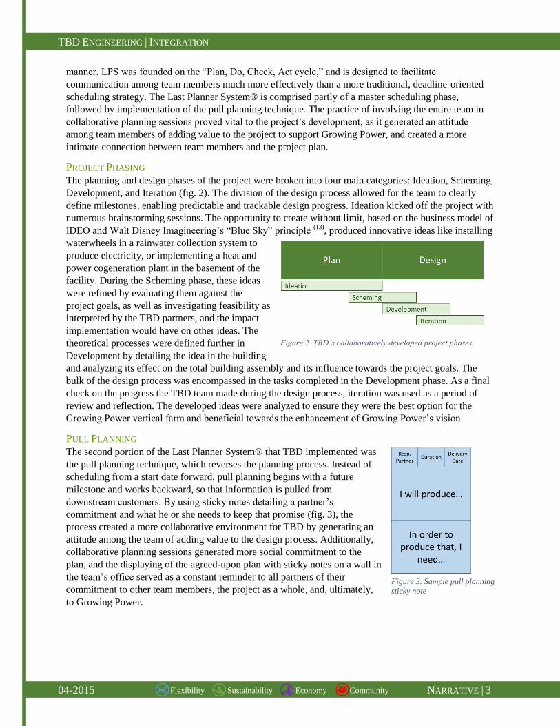
PROJECT PHASING
The planning and design phases of the project were broken into four main categories: Ideation, Scheming,
Development, and Iteration (fig. 2). The division of the design process allowed for the team to clearly
define milestones, enabling predictable and trackable design progress. Ideation kicked off the project with
numerous brainstorming sessions. The opportunity to create without limit, based on the business model of
IDEO and Walt Disney Imagineering’s “Blue Sky” principle (13)
, produced innovative ideas like installing
waterwheels in a rainwater collection system to
produce electricity, or implementing a heat and
power cogeneration plant in the basement of the
facility. During the Scheming phase, these ideas
were refined by evaluating them against the
project goals, as well as investigating feasibility as
interpreted by the TBD partners, and the impact
implementation would have on other ideas. The
theoretical processes were defined further in
Development by detailing the idea in the building
and analyzing its effect on the total building assembly and its influence towards the project goals. The
bulk of the design process was encompassed in the tasks completed in the Development phase. As a final
check on the progress the TBD team made during the design process, iteration was used as a period of
review and reflection. The developed ideas were analyzed to ensure they were the best option for the
Growing Power vertical farm and beneficial towards the enhancement of Growing Power’s vision.
PULL PLANNING
The second portion of the Last Planner System® that TBD implemented was
the pull planning technique, which reverses the planning process. Instead of
scheduling from a start date forward, pull planning begins with a future
milestone and works backward, so that information is pulled from
downstream customers. By using sticky notes detailing a partner’s
commitment and what he or she needs to keep that promise (fig. 3), the
process created a more collaborative environment for TBD by generating an
attitude among the team of adding value to the design process. Additionally,
collaborative planning sessions generated more social commitment to the
plan, and the displaying of the agreed-upon plan with sticky notes on a wall in
the team’s office served as a constant reminder to all partners of their
commitment to other team members, the project as a whole, and, ultimately,
to Growing Power.
Figure 2. TBD’s collaboratively developed project phases
Figure 3. Sample pull planning
sticky note

TBD ENGINEERING | INTEGRATION
04-2015 NARRATIVE | 4 Flexibility Sustainability Economy Community
The initial implementation of the pull planning technique posed a challenge due
to many design partners’ lack of familiarity with the strategy. To familiarize the
team with the concept of pull planning, TBD engaged in an informal simulation
in which the team applied the method to plan and execute the construction of a
small tower out of children’s interlocking toy blocks (fig. 4). This initial session
enlightened many team members to the importance of effective exchange of
information to the delivery of a quality design, as even something as simple as a
tower of blocks did not go as smoothly as the team had envisioned. Throughout
all four phases of TBD’s planning
and design process, pull planning
sessions (fig. 5) were held on a
weekly basis to plan the
development of the team’s Integrated Design Packages (p. 6).
Several key exchanges of information occurred during these
sessions that would not have normally taken place, such as
the interaction between mechanical, structural, and
construction partners in the design of the floor slab system of
the Growing Spaces (p. 12) and the plenum of the Gathering
Space (p. 14).
MAPPING PROJECT PROCESSES
Mapping project processes is a technique often used by the research community in order to understand
project development and establish a baseline plan against which to measure actual progress. Although
collaborative planning through LPS is a
great facilitator for information exchange, a
logical process flow diagram, (fig. 6, D2) is
beneficial in enabling all partners to visually
understand how each fits into the broader
picture of developing an integrated design.
As a form of documentation of the
collaboratively developed plan, the process
map allowed the team to look ahead to
understand the overall direction of the team.
Process mapping is an important tool to support team integration, which allowed TBD to eliminate waste
in the design process and support all four major project goals.
CO-LOCATION The location of essential team members in a common space
significantly contributes to an integrated design process by making
team members easily accessible for questions, responses, and
spontaneous integrated design sessions. Throughout the entirety of
the planning and design phases, TBD team members utilized an
easily accessible, secure, co-located office for the majority of effort
towards the Growing Power facility design. The space had enough
room for all team members to work comfortably, held all team
computers and drawing tables, had ample wall space for the
hanging of relevant material, and contained a meeting space
complete with a SMART Board (fig. 7).
Figure 4. Informal LPS
implementation
Figure 5. Snapshot of TBD collaborative planning
Figure 6. Snapshot of TBD project process map
Figure 7. Components of co-located office

TBD ENGINEERING | INTEGRATION
04-2015 NARRATIVE | 5 Flexibility Sustainability Economy Community
Locating the team members in the same room also permitted the opportunity to witness the development
of the design as it was created. This kept all pertinent players informed of the design and its process while
simultaneously alerting them to their required deliverables necessary for the advancement of design. Co-
location also enhanced design by providing continuous review by multiple team members, ensuring an
optimized product.
FACE TO FACE COMMUNICATION Whether team members were working on the Growing Power project, or other individual projects, an
enormous portion of their time was spent together in the co-located office space, which allowed for
frequent face to face interaction between all team members, the team’s preferred method of
communication. Not only did face to face interaction contribute to the team building process of TBD,
which in turn developed trust in team members, but also enabled effective flows of information through
verbal communication. Everyone could be reached quickly if a question pertaining to their field of
expertise arose, and the questions were promptly answered. The co-location of the team also opened all
conversations to input from other team members, allowing them to provide aid from their own
perspective, resulting in spontaneous, integrated design sessions.
DIGITAL COMMUNICATION While face to face interaction was the preferred method of communication, it was not always an available
option. An effective transfer of information is necessary to the success of an integrated design project and
communication channels must be clearly identified to easily reach
team members. TBD identified four methods of digital
communication to be used during the planning and design phases of
the project to reach team members and information (fig. 8). The
electronic files created during design, including plans, research
articles, calculations, spreadsheets, and reports, were uploaded to
Box, a secure online file sharing and cloud content management service. Any file a team member
uploaded to Box could be viewed by the entire team, creating a way for information to be pulled quickly
when needed without direct contact between partners. The model files were the only files not saved to
cloud storage, but were instead saved locally on a secure server. Cell phones were utilized when questions
needed to be answered or decisions needed to be made quickly with the input of one individual. Publicly
displaying the cell numbers of the team members provided the option to be contacted when needed.
GroupMe, a mobile group messaging app, was an agreed-upon method to reach all partners
simultaneously. This became a highly useful tool for decision making that required the input of a group
when not all team members could be present in the co-located office.
DECISION MAKING PROCESS In order to ensure that all major decisions were made in support of the defined project goals of economy,
sustainability, flexibility, and community, a decision matrix was conceived that facilitated team analysis
of those decision (fig. 9, D1). TBD’s decision matrix discouraged design partners from producing a
system that they were familiar with, by encouraging the exploration of multiple options to design a
facility that most
effectively balanced all
project goals. After
developing a list of ideas,
the design partner most
familiar with the system
Figure 8. TBD digital communication methods
Figure 9. Snapshot of TBD decision matrix

TBD ENGINEERING | INTEGRATION
04-2015 NARRATIVE | 6 Flexibility Sustainability Economy Community
evaluated each option against the four primary project goals, as well as secondary intra-team goals. Final
decisions were made as a collective unit, and consisted of discussing the tradeoff that took place between
the system options and how they contributed to each goal.
To support Growing Power’s goal of delivering an economic facility, cost trending was also used as a tool
to inform design decisions. Management partners employed the use of “over-the-shoulder” (11)
(OTS)
estimating in order to maintain an accurate database of the design’s cost. The OTS strategy involves
defining design milestones to perform a detailed financial estimate of the design to date. Each system of
the facility was tracked independently and charted on a graph (fig. 10, D3), and constant evaluation of the
project’s total value against Growing Power’s defined target allowed the team to identify if any portion of
the facility was experiencing an alarming trend in cost growth, and facilitated numerous discussions
throughout the design process. For example, the
design and installation of an on-site combined
heat and power (CHP) facility was identified
early in the design process as a potential option to
support Growing Power’s goal of community, but
represented a significant portion of the
mechanical system’s target value. This design
option triggered further discussion and
justification from an economic standpoint, and
was ultimately accepted (M|10). Throughout the
planning and design process, a contingency was
carried to account for potential unknowns,
inversely reflecting the level of confidence in the
evaluation of the current estimate against the
design target.
INTEGRATED DESIGN PACKAGES Rather than designing the entire facility independent of each other’s progress, TBD chose to group similar
space types into Integrated Design Packages
(IDP). After analysis of the desired program, TBD
identified five major IDPs within the footprint of
the facility (fig. 11, SD|III), and identified the
enclosure as another key IDP. Throughout the
design phases, the team targeted efforts on one
specific design package at a time, creating more
interactions than a traditional design strategy.
Working within the IDP better displayed the
interactions among building systems and
facilitated discussions within the team regarding
potential conflicts. The near real-time discovery
and resolution of collisions between systems
allowed for much quicker design progression, as
the team spent less time in traditional coordination
meetings and more time detailing and developing
the facility design.
Figure 11. TBD Integrated Design Packages
Figure 10. Evaluation of project cost against established target

TBD ENGINEERING | INTEGRATION
04-2015 NARRATIVE | 7 Flexibility Sustainability Economy Community
BUILDING INFORMATION MODELING Building Information Modeling (BIM) is both a tool and a process that is designed to support the
integration and flow of information among team members. The application of BIM is becoming the new
standard of practice in the AEC industry, although the quantification of the value it adds is difficult due to
varying levels of implementation on a case by case basis. However, promising data was produced from a
case study of the Pegula Ice Arena, which earned a 2014 BIM Award from the American Institute of
Architects, where research measured a savings of over $1 million. (3)
However, the power of BIM is not
limited to achieving only goals related to economy, but can also allow the team to develop a more
sustainable building through energy analysis, utilize the information to improve upon the initial prototype,
and help further Growing Power’s mission of educating the community.
BIM EXECUTION PLANNING In order to take full advantage of the value that can be added through the use of BIM, a plan was put in
place for the implementation of the tool throughout the lifecycle of both the project and the facility
(SD|IV). Utilizing the BIM Project Execution Planning Guide (11)
, TBD developed a detailed plan for the
utilization of BIM throughout the project, following a process consisting of defining BIM goals,
identifying BIM uses, and recognizing how information should be exchanged between the different tools.
BIM GOALS AND USES
A key aspect of the Planning Guide is the idea to “begin with the end in mind.” Instead of identifying how
BIM can add value to a project from the planning phase forward through design, construction, and
operations, reversing the process ensures that each use of BIM is working toward an end goal, and that
developed information is leveraged to improve design communication and integration
A key goal for TBD was to allow for the Growing Power facility designed in Milwaukee, WI to be a
flexible prototype that is continuously improved upon with each new facility’s construction in a different
location. As
such, the
efficient
operation of the
facility was seen
as paramount to
the success of
the overall
project. Goals
were then
identified for the
construction of
the building, and
through the
design and
planning phases
(fig. 12, SD|IV). Figure 12. TBD BIM goals, planned with the operation phase in mind

TBD ENGINEERING | INTEGRATION
04-2015 NARRATIVE | 8 Flexibility Sustainability Economy Community
After clear
definition of the
goals TBD strived
to achieve through
the implementation
of BIM,
applications of
different tools were
identified to
support the pursuit
of those goals, (fig.
13, SD|IV). The
primary uses were
divided by lifecycle phase, and further by TBD’s four custom phases which fit into the more generic
“planning” and “design” phases.
BIM PROCESS AND INFORMATION EXCHANGES
With the goals and uses defined for the implementation of BIM throughout the Growing Power facility’s
lifecycle, a process was undertaken to define how the partners’ models needed to develop and how
software would interface to perform each of the BIM
uses. To begin, a high-level process was modeled for
the team (fig. 14) in order to guide the implementation
of the BIM efforts, beginning with preliminary
programming and energy modeling. Once designs
were authored, they were synchronized to an
integrated central model, where review, coordination,
and analysis could take place, aiding the iterative,
integrated nature of TBD’s design process. In order to
support the design authoring portion of the models,
the AIA’s Level of Development (LOD) matrix (14, 15)
was utilized along with AIA’s LOD Specification.(16)
TBD designed specific information exchanges to
leverage the software at hand, partaking in a detailed
session defining how information could be extracted
from the intelligent model and used to run simulations
and analyses (SD|V).
DESIGN INTEGRATION The result of Total Building Design’s integrated team processes is a highly integrated facility to turn over
to the ownership partners at Growing Power. While the entire building required efficient coordination and
communication, three key aspects of the design stood above the rest as considerable focused efforts of the
team. The context of the facility is extremely important when analyzing its interior systems, as were the
facility’s enclosure, the community gathering space, and the growing spaces.
Figure 13. BIM uses per project phase
Figure 14. Sample BIM process

TBD ENGINEERING | INTEGRATION
04-2015 NARRATIVE | 9 Flexibility Sustainability Economy Community
BUILDING CONTEXT In order to engage design
partners in a more focused
approach, the program described
in schematic documents provided
to TBD was categorized into
integrated design packages (p. 6,
SD|III) based on the intended use
of the space. After analyzing the
schematic documents, the project
goals, and internal team goals,
five distinct design packages
were identified: growing spaces,
administration and learning
space, gathering space, market
space, and support spaces, or
back of house (fig. 15).
TBD designed the Growing Power facility to take advantage of iconic architectural features and
innovative, sustainable integrated building systems. The result, is a multi-use facility comprised of four
terraced growing spaces (green) that showcase a flexible layout of aquaponic farming techniques (SD|XI),
connected to the interior spaces with specially designed view corridors. Additionally, the facility will
include two levels of educational and administrative space (purple) to actively support Growing Power’s
goal of community education
and outreach. Below the
administrative and learning
spaces is a level of gathering,
also designed to enhance
Growing Power’s outreach in
the community with ample
space for lectures,
presentations, and storage to
support a flexible layout. The
storefront of the facility invites
community members into
Growing Power’s market
(cyan), which sells the
sustainably grown produce
from the growing spaces
above. To support the entire
facility, a back of house area (basement, not shown) includes space for shipping and receiving, a
workshop for the creation of plant beds, and mechanical and electrical zones. All packages are connected
by a grand hybrid switchback staircase to unite the operation in connecting the surrounding community to
all aspects of Growing Power. The facility (fig. 16) is supported by a rigid steel frame (red), conditioned
with a water source heat pump distribution system (blue), and features efficient LED lighting controlled
by occupancy and daylight sensors (yellow).
Figure 15. TBD Integrated Design Packages
Figure 16. Rendering of Growing Power facility

TBD ENGINEERING | INTEGRATION
04-2015 NARRATIVE | 10 Flexibility Sustainability Economy Community
BUILDING ENCLOSURE DESIGN The selection of an enclosure impacts design decisions for all team
members, as well as defines the image of the Growing Power
organization to the surrounding community. Multiple options for an
enclosure were considered during the planning and design phases
using TBD’s decision matrix (D1) to ensure the final selection
supported project goals of flexibility, sustainability, economy, and
community. After thorough analysis, a rainscreen assembly (SD|VII)
was determined to be the most beneficial for the project needs,
especially supporting Growing Power’s goal of flexibility. The
rainscreen system (fig. 17) consists of metal studs, an exterior
fiberglass sheathing layer, moisture barrier, Z-furring channel, rigid
insulation, and architectural façade panels. Numerous components of
the rainscreen, such as the insulation, can be adapted based on
specific locations’ project conditions, supporting Growing Power’s
effort to use the facility in Milwaukee as a national prototype. Additionally, the enclosure is easily
constructed (CM|9) and alleviates maintenance issues, like efflorescence and moisture penetration,
associated with other systems. The rainscreen system created easier collaboration between the
construction, structural, and mechanical partners since the wall could utilize multiple insulation R-values
without added challenges to the respective systems.
RAINSCREEN BACKUP SYSTEM The rainscreen assembly permits a great deal of flexibility in the design of its structural backup, allowing
for either CMU or steel stud backup depending on the specific load case of a certain location (Struc|13).
The system designed for Growing Power in Milwaukee consists of steel studs which reduced the
enclosure’s backing weight, aiding in the economization of the structure’s perimeter beams and slightly
increasing the usable interior space. The specific arrangement of studs was verified using AISIWIN
structural modeling, but the stud size, spacing, and strength is also a flexible aspect of the rainscreen’s
backup. The wind loads of Miami-Dade County pose a situation that requires consideration for high wind
loads, but the flexibility of the rainscreen’s backup allows the assembly to be an effective enclosure in all
locations.
MOISTURE PROTECTION AND
INSULATION FOR ANY CLIMATE The differentiating characteristic of the
rainscreen theory is to prevent moisture
from penetrating the enclosure, which
usually occurs due to an air pressure
differential across the enclosure created
by windy conditions. Positive pressure
created outside the enclosure in these
conditions results in moisture being
driven into the wall cavity in more
traditional enclosure systems. The
rainscreen assembly eliminates the
pressure differential across the exterior
wall through an open joint assembly—
Figure 17. Virtual mockup of rainscreen
Figure 18. Equal Pressurization Barrier Section
Equal Pressurization Barrier
The rainscreen
system acts as a
double line of
defense in building
moisture
penetration. The
architectural panels
block driving wind,
which equalizes
pressure across the
assembly and avoids
pressure driven
moisture
penetrations into the
facility (SD|VII)

TBD ENGINEERING | INTEGRATION
04-2015 NARRATIVE | 11 Flexibility Sustainability Economy Community
essentially leaving small gaps between façade panels. By allowing rain and air between the façade panel
and the bulk of the rain screen’s thermal and structural backup system, an equal pressure is achieved
across the wall, which aids the traditional moisture barrier in keeping the Growing Power facility safe
from moisture penetration, (fig. 18).
Additionally, the rainscreen’s utilization of rigid insulation outside the fiberglass sheathing layer allows
for the enclosure to be thermally efficient in any location. The R-value of the insulation can be designed
for any specific location based on the heating and cooling loads of the region. To simulate the flexibility,
TBD modeled the Growing Power facility in both Milwaukee and Miami with Trane TRACE 700,
allowing the team to analyze the rainscreen’s performance against the baseline ASHRAE 90.1, which
proved that the rainscreen can meet the baseline in both locations with a simple upgrade of the rigid
insulation layer. In fact, the assembly can greatly outperform the ASHRAE baseline in both climates (fig.
19, Mech|2).
ARCHITECTURAL CONTEXT Although the rainscreen assembly provides many benefits through its
equal pressurization theory and the flexibility of its backing system and
thermal performance, a major impact of the facility’s enclosure is its
architectural style’s perception by the surrounding community. TBD
chose a terracotta façade panel for the majority of Growing Power’s
prototype in Milwaukee due to its natural composition and reflection of
the community in which the facility is to be located. The terracotta panels
also complement the sizing and placement of the glazing (fig. 20).
Analysis in DAYSIM and Trane TRACE 700 resulted in the selection of a
glazing panel with an appropriate U-value and solar heat gain coefficient
to reduce heat and cooling loads of the facility, supporting Growing
Power’s goal of an economically operable facility while maintaining the
architectural integrity of the facility’s façade (Elec|10). Furthermore, the
team investigated the use of vertical fins on the east and west facades to
block direct, low-angle sunlight from penetrating the facility’s interior
spaces and further reducing the heating and cooling loads, resulting in
slightly reduced energy consumption.
Figure 19. Heating and cooling loads of Milwaukee (left)and Miami (right)
Figure 20. Façade complemented by glazing

TBD ENGINEERING | INTEGRATION
04-2015 NARRATIVE | 12 Flexibility Sustainability Economy Community
GROWING SPACES Growing Power’s primary mode of community outreach and education is through the demonstration of
sustainable growing techniques. Currently, this process takes place in multiple greenhouses on-site, which
are vital in order for the organization to provide “important opportunities for individuals and communities
to network with each other as they work in partnership to promote food security and environmentally
sound food production practices.” The success of the vertical farming facility depends significantly on the
ability for all four greenhouses to operate efficiently. As a space for the growth and maintenance of plant
life is also heavily reliant on various building systems, the greenhouses were a major point of integration
throughout TBD’s design process (SD|VIII).
ORIGINAL DESIGN The original design for the Growing Power facility, contained in schematic documents provided to TBD
(fig. 21), included four levels of rooftop greenhouses to support the organization’s efforts to educate the
community through demonstration of different growing techniques. While understandably an effort to
provide an economic solution for Growing Power, the specified pre-manufactured greenhouses left TBD
room for improvement. The rooftop greenhouses originally specified for the Growing Power facility rose
to a peak height of 26 feet above the finished floor and consisted completely of exterior glazing. Through
extensive research and analysis with various BIM tools, TBD made the decision to investigate
redesigning the growing spaces to allow for optimum plant growth, a safe and flexible layout of
aquaponic systems, reduced conditioning costs, and the creation of an iconic architectural statement when
viewed from the surrounding community.
A MORE EFFICIENT GROWING SPACE TBD’s initial investigation of the specified pre-
manufactured rooftop greenhouses suggested that
the space contained an unnecessary volume of
space to condition, an inefficient plant layout, and
excessive glazing (Elec|5). Further research also
indicated that the pre-manufactured greenhouses
could not be reduced to a favorable height while
maintaining the necessary fire rating to comply
with IBC code (Struc|11). TBD discovered that a
custom greenhouse structure could be designed
that contained less volume and a more efficient
glazing layout, allowing the mechanical system to more efficiently condition the space without negative
impacts on the natural light reaching the plant beds within the space. Additionally, a custom-designed
greenhouse structure provided the potential to take into account multiple locations’ load cases, resulting
in a more prototypable space.
In order to minimize the roof structure’s effect on the natural light obtained by the plant beds, multiple
concepts were devised and analyzed simultaneously in DAYSIM and RAM to ensure both their structural
integrity and their impact on natural light reaching the plant beds (Elec|6). While large steel elements
could have been easily designed and implemented, their negative impact on the plants’ lighting
significantly hindered the greenhouse’s ability to operate efficiently, detracting from Growing Power’s
goal of an economically operated facility to educate the community. The final design consisted of a
glulam structure, sized as narrowly as possible to allow an optimum amount of light to reach the beds and
provide a greenhouse design that is as conducive to efficient plant growth as possible. The use of heavy
Figure 21. Elevation comparison of original greenhouse (left) and TBD
custom design (right)

TBD ENGINEERING | INTEGRATION
04-2015 NARRATIVE | 13 Flexibility Sustainability Economy Community
timber also alleviated the fireproofing concern regarding the greenhouse roof (Struc|11), and provided a
unique architectural feature in the use of a sustainable material in the sawtooth profile of the greenhouses
(fig. 21).
Further daylighting analysis proved that the original design contained excessive glazing that created a
greater conditioning load than necessary. In order to increase the thermal resistivity of the greenhouses’
walls without negatively impacting the plants’ growth, the facility’s rainscreen façade was carried from
the main portion of the building to the east and west sides of the greenhouse, as well as partially up the
south wall (REF).
A FLEXIBLE FLOOR LAYOUT Another major goal for TBD was to provide Growing
Power with the flexibility to install and demonstrate a
variety of growing techniques throughout the rooftop
greenhouses. An aquaponic system (Mech|3) was a
targeted system and provided numerous challenges
and constraints to the flexibility desired. The tanks
designed for the aquaponic system account for a large
load on the structural slab, requiring the slab to be
designed for much higher live loads than normal
(Struc|4) in order for the tanks to be placed anywhere
in the greenhouse and to allow Growing Power the
flexibility to place an aquaponic system in the
greenhouse on any level.
An aquaponic system also consists of a great deal of water piping at the floor level, posing a safety hazard
for those exploring the space. As an educational tool for the community, safety was a vital consideration
for the growing spaces. To reduce the amount of piping resting on the greenhouse floor, TBD designed a
unique, grated floor system that allowed the pipe to be routed under the raised grate (fig. 22, SD|X).
Coincidentally, the plenum below the floor grate also created space to run conduit and other mechanical
piping, removing as many obstructions as possible from blocking the plants’ sunlight.
As the greenhouses were designed to house numerous systems containing vast amount of water, water
leakage was a major consideration that needed to be taken into account throughout the design’s
development. After investigating multiple options, a solution was designed providing two layers of
defense against water penetration into the Growing Power facility (fig. 22, Struc|12).
EFFICIENCY THROUGH AN INTEGRATED APPROACH While the introduction of pre-manufactured greenhouses could provide a much lower up front
construction cost, their implementation left room for improvement with respect to the project goals of
community education, flexibility, and long term economy. TBD’s integrated design approach led to the
creation of a greenhouse design that more effectively supported those goals. Through the definition of an
Integrated Design Package consisting strictly of the growing spaces on each level, TBD focused efforts of
all team members on the greenhouses at once, devising a solution that benefitted all design partners, but
most importantly Growing Power. The use of various analysis tools was essential in order to balance the
needs of each building system and the plant life within, and the communication facilitated by
collaborative planning sessions provided pertinent information to all team members as the design
developed, allowing TBD to design a flexible space to house numerous types of growing systems, while
efficiently conditioning the space and quickening the facility’s watertight milestone.
Figure 22. Detail view of TBD’s greenhouse floor system

TBD ENGINEERING | INTEGRATION
04-2015 NARRATIVE | 14 Flexibility Sustainability Economy Community
GATHERING SPACE Growing Power exists not only to grow food, but also to grow the local community in which the facility
and organization are situated. A key support to the goal of community outreach and education is the
Gathering design package, highlighted by the completely open plan Gathering Space located on the
facility’s second floor.
ORIGINAL DESIGN The schematic documents provided to TBD included the aforementioned space on the second floor of the
Growing Power facility. However, while the original plan was spacious enough to host a large gathering
of people, the columns in the plan created a visual and physical obstruction of the space (fig. 23). TBD
fully agreed with the placement of the gathering space in the context of the facility—the second floor is
slightly less public than the market below, but much more so than the private education and
administrative spaces above. However, in order to support Growing Power’s goal of community
involvement and outreach, TBD identified an opportunity to improve upon the original design for the
gathering space by removing two interior columns (SD|XII). The removal of the interior columns resulted
in more usable space for seating in a large presentation setting, as well as uninterrupted views to those
seated farthest from the presenter. The team proceeded with the decision to support Growing Power’s
goal of community with the understanding that developing a successful design would take great effort by
all partners and a highly integrated approach.
TBD IMPROVEMENTS AND CHALLENGES By focusing the entire team on the Gathering Space design package at the same time, communication was
facilitated through the use of collaborative planning (p. 3). This ensured that the design process went as
smoothly as possible by identifying key points of interaction that needed to occur in the process. The
integrated planning session determined that the first step of redesigning the open Gathering Space was to
begin with a discussion of installation sequencing and shipping logistics to ensure that any structural
element that was designed supported the construction sequencing plan, or that the plan could be altered to
make any necessary accommodations.
In the scheming phase of the Gathering Space’s development, the
team convened to discuss options to overcome the challenge of
eliminating the two interior columns. This discussion resulted in
numerous design guidelines for all systems to be integrated
within the plenum space, such as the idea that the structural
members needed to be shallow enough to allow duct to pass
Figure 23. Comparison of original design for Gathering Space (left) and TBD’s open plan (right)
Figure 24. Transfer girders (red) open
the Gathering Space floor layout

TBD ENGINEERING | INTEGRATION
04-2015 NARRATIVE | 15 Flexibility Sustainability Economy Community
between the steel and the space’s ceiling, or deep enough to safely cut through the members.
Through the extensive use of RAM modeling, TBD
determined that the best option to transfer the facility’s
load to the exterior columns was through the utilization of
three transfer elements, (fig. 24, Struc|7). With the
understanding that these elements had the potential to
consume most of the plenum space, TBD designed a
linear scheme of mechanical and electrical equipment and
fixtures that fit between the locations of the three transfer
elements. The size of some mechanical equipment posed
a potential challenge with the reduced plenum space, so
the team determined that space along the exterior walls
could house the heat pumps feeding the space.
With a schematic layout devised, TBD moved forward developing the integrated design. Again the
targeted approach of the team proved extremely beneficial, as all partners modeled their designs
simultaneously, with the structural layout slightly leading the MEP system layout. Coordination views
developed in Revit (fig. 26), also proved invaluable to the team in the modeling process, as they allowed
all partners to author their design within the context of the entire, integrated space. Continuous
coordination by all design partners significantly reduced the number of conflicts that needed to be
resolved in coordination sessions (SD|VI).
The decision to open up the space also resulted in challenges to be overcome
during the construction process. Structural members of the depth and weight
utilized in the Gathering Space are not rolled at all steel mills, and lengths
exceeding that of a standard semi-permanent trailer require permits to travel
on various highways, presenting the potential for significant added costs.
Additionally, the massive members posed a challenge in that they were
preliminarily identified as a potential to be the project’s critical pick (CM|9).
However, extensive research resulted in solutions to all challenges, as TBD
identified a mill in Arkansas and fabricator near the Milwaukee site, with a
path routed by a shipping partner that resulted in a nominal transportation fee
(CM|9).
EFFICIENCY THROUGH AN INTEGRATED APPROACH Utilizing TBD’s integrated design approach and BIM technology, a solution beneficial to all designed
systems and the building as a whole was created. While the original design contained in schematic
documents was undoubtedly a simpler option to construct and an attempt to provide a more economic
design, TBD determined that its design left room for improvement, specifically in its contribution to the
space’s community education aspect. While altering the design to feature a completely open second floor
created multiple challenges, the strategies implemented by the team allowed a successful design to be
achieved. Through the definition of a specific design package, TBD focused all design partners in the
space at once. The utilization of collaborative planning facilitated important discussion regarding the
interactions between various design systems, resulting in such ideas as making the transfer elements
either deep enough to cut through or shallow enough to run air distribution between the steel and the
ceiling. The end design’s linear lighting and mechanical scheme (fig. 25) was the result of a defined
“coordination view” in each design partner’s virtual model, allowing the team to continuously coordinate
the space to alleviate any possible issues, or catalyze discussion among the team.
Figure 26. Coordination view in Revit
Figure 25. MEP linear scheme to coordinate with girders