vhf transceivers ic-f31gt/gs ic-f31gt-l ic-f31gs-l · vhf transceivers ic-f31gt/gs ic-f31gt-l...
TRANSCRIPT
INSTRUCTION MANUAL
UHF TRANSCEIVERS
iC-f41gt/gs
VHF TRANSCEIVERS
iC-f31gt/gsiC-f31gt-liC-f31gs-l

i
FOREWORDThank you for purchasing the IC-F31GT/IC-F31GS, IC-F31GT-L/ IC-F31GS-L, IC-F41GT/IC-F41GS vhf/uhf transceivers. READ ALL INSTRUCTIONS carefully and completely before using the transceiver.SAVE THIS INSTRUCTION MANUAL–This instruction manual con-tains important operating instructions for the transceiver.
EXPLICIT DEFINITIONS
WORD DEFINITION
RWARNINGPersonal injury, fire hazard or electric shock may occur.
CAUTION Equipment damage may occur.
NOTEIf disregarded, inconvenience only. No risk of personal injury, fire or electric shock.
INSTALLATION NOTES• When transmitting with a portable radio, hold the radio in a verti-
cal position with its microphone 5 to 10 cm away from your mouth. Keep the antenna at least 2.5 cm from your head and body.
• If you wear a portable two-way radio on your body, ensure that the antenna is at least 2.5 cm from your body when transmitting.
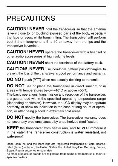
PRECAUTIONSCAUTION! NEVER hold the transceiver so that the antenna is very close to, or touching exposed parts of the body, especially the face or eyes, while transmitting. The transceiver will perform best if the microphone is 5 to 10 cm away from the lips and the transceiver is vertical.
CAUTION! NEVER operate the transceiver with a headset or other audio accessories at high volume levels.
CAUTION! NEVER short the terminals of the battery pack.
CAUTION! NEVER use non-Icom battery packs/chargers to prevent the loss of the transceiver’s good performance and warranty.
DO NOT push [PTT] when not actually desiring to transmit.
DO NOT use or place the transceiver in direct sunlight or in areas with temperatures below –10°C or above +50°C.The basic operations, transmission and reception of the transceiver, are guaranteed within the specified operating temperature range (depending on version). However, the LCD display may be operate correctly, or show an indication in the case of long hours of opera-tion, or after being placed in extremely cold areas.
DO NOT modify the transceiver. The transceiver warranty does not cover any problems caused by unauthorized modification.
KEEP the transceiver from heavy rain, and NEVER immerse it in the water. The transceiver construction is water resistant, not waterproof.
ii
Icom, Icom Inc. and the Icom logo are registered trademarks of Icom Incorpo-rated (Japan) in Japan, the United States, the United Kingdom, Germany, France, Spain, Russia and/or other countries.All other products or brands are registered trademarks or trademarks of their re-spective holders.

TABLE OF CONTENTS
iii
FOREWORD ..................................................................................iEXPLICIT DEFINITIONS ................................................................iINSTALLATION NOTES ..................................................................iPRECAUTIONS ............................................................................. iiTABLE OF CONTENTS ................................................................ iii1 ACCESSORIES ........................................................................1 n Accessory attachment...........................................................12 PANEL DESCRIPTION ........................................................2–4 n Switches, controls, keys and connectors ..............................2 n Function display ....................................................................43 BATTERY PACKS ..............................................................5–10 n Battery pack replacement .....................................................5 n Battery cautions ....................................................................6 n Battery charging ....................................................................7 n Charging NOTE .....................................................................9 n Battery case (Option) ..........................................................104 PROGRAMMABLE FUNCTIONS ....................................11–15 n General ...............................................................................115 CONVENTIONAL OPERATION ..........................................16–18 n Receiving and transmitting ..................................................16 n Call procedure .....................................................................17 n Tx code channel selection ...................................................18 n Manual 5-tone codes ..........................................................18 n Transmitting notes ...............................................................186 OTHER FUNCTIONS .............................................................19 n DTMF PAGER/CODE SQUELCH .......................................197 OPTIONAL UNIT INSTALLATION .........................................20 n Installation ...........................................................................208 CLONING ...............................................................................21 n Cloning ................................................................................219 OPTIONS ..........................................................................22–2310 ABOUT CE .............................................................................24
1ACCESSORIES
1
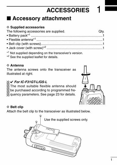
n Accessory attachmentD Supplied accessoriesThe following accessories are supplied. Qty.• Battery pack*1 .............................................................................1• Flexible antenna*1 .......................................................................1• Belt clip (with screws) ..................................................................1• Jack cover (with screw)*2 ............................................................1
*1 Not supplied depending on the transceiver’s version.*2 See the supplied leaflet for details.
D AntennaThe antenna screws onto the transceiver as illustrated at right.
✔For IC-F31GT-L/GS-L The most suitable flexible antenna should be purchased according to programmed fre-quency parameters. See page 23 for details.
D Belt clip Attach the belt clip to the transceiver as illustrated below.
Use the supplied screws only.

PANEL DESCRIPTION
2
2n Switches, controls, keys and connectors
q
w
e
r
t
y
u
i
o
!0
!1
Microphone
Speaker
!2
D Programmable key reference
F0 (Red) P0
F1 (Black) P1
F2 (Black) P2
F3 (Black) P3
2PANEL DESCRIPTION
3
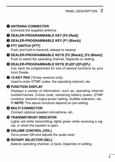
q ANTENNA CONNECTORConnects the supplied antenna.
w DEALER-PROGRAMMABLE KEY [F0 (Red)]
e DEALER-PROGRAMMABLE KEY [F1 (Black)]
r PTT SWITCH [PTT]Push and hold to transmit; release to receive.
t DEALER-PROGRAMMABLE KEYS [F2 (Black)], [F3 (Black)]Push to select the operating channel. Depends on setting.
y DEALER-PROGRAMMABLE KEYS [P0]/[P1]/[P2]/[P3]Can each be programmed for one of several functions by your Icom Dealer.
u 10-KEY PAD (10-key versions only)Used to enter DTMF codes, the operating channel, etc.
i FUNCTION DISPLAYDisplays a variety of information, such as, operating channel number/names, 5-tone code, remaining battery power, DTMF numbers, transmit output power setting, Audible indication, etc.
NOTE: The above functions depend on pre-setting.
o MULTI CONNECTORConnect optional speaker-microphone, etc.
!0 TRANSMIT/BUSY INDICATORLights red while transmitting; lights green while receiving a sig-nal, or when the squelch is open.
!1 VOLUME CONTROL [VOL]Turns power ON and adjusts the audio level.
!2 ROTARY SELECTOR [SEL]Selects operating channel, or bank. Depends on setting.
PANEL DESCRIPTION2
4
n Function display
q
w
e
r t
y
u
i
o
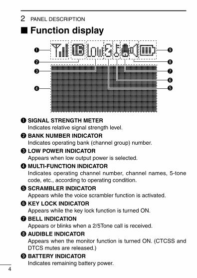
q SIGNAL STRENGTH METERIndicates relative signal strength level.
w BANK NUMBER INDICATORIndicates operating bank (channel group) number.
e LOW POWER INDICATORAppears when low output power is selected.
r MULTI-FUNCTION INDICATORIndicates operating channel number, channel names, 5-tone code, etc., according to operating condition.
t SCRAMBLER INDICATORAppears while the voice scrambler function is activated.
y KEY LOCK INDICATOR Appears while the key lock function is turned ON.
u BELL INDICATIONAppears or blinks when a 2/5Tone call is received.
i AUDIBLE INDICATORAppears when the monitor function is turned ON. (CTCSS and DTCS mutes are released.)
o BATTERY INDICATORIndicates remaining battery power.
3BATTERY PACKS
5
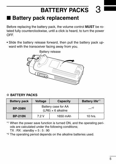
n Battery pack replacementBefore replacing the battery pack, the volume control MUST be ro-tated fully counterclockwise, until a click is heard, to turn the power OFF.
• Slide the battery release forward, then pull the battery pack up-ward with the transceiver facing away from you.
Battery release
D BATTERY PACKS
Battery pack Voltage Capacity Battery life*1
BP-208NBattery case for AA (LR6) × 6 alkaline
—*2
BP-210N 7.2 V 1650 mAh 10 hrs.
*1 When the power save function is turned ON, and the operating peri-ods are calculated under the following conditions;
TX : RX : standby = 5 : 5 : 90*2 The operating period depends on the alkaline batteries used.
3 BATTERY PACKS
6
n Battery cautions• CAUTION! NEVER short terminals (or charging terminals) of the
battery pack. Also, current may flow into nearby metal objects such as a necklace, so be careful when placing battery packs (or the transceiver) in handbags, etc.Simply carrying with or placing near metal objects such as a neck-lace, etc. may cause shorting. This may damage not only the bat-tery pack, but also the transceiver.
• NEVER incinerate used battery packs. Internal battery gas may cause an explosion.
• NEVER immerse the battery pack in water. If the battery pack becomes wet, be sure to wipe it dry BEFORE attaching it to the transceiver.
• Clean the battery terminals to avoid rust or miss contact.• Keep battery contacts clean. It’s a good idea to clean battery ter-
minals once a week.
If your battery pack seems to have no capacity, even after being charged, completely discharge it by leaving the power ON over-night. Then, fully charge the battery pack again. If the battery pack still does not retain a charge (or only very little charge), a new bat-tery pack must be purchased. (p. 22)

3BATTERY PACKS
7
n Battery charging
D Rapid charging with the BC-119NThe optional BC-119N provides rapid charging of the battery pack.The followings are additionally required:• One AD-101 (purchase separately).• An AC adapter (may be supplied with the BC-119N depending on
version).
BC-119N+ AD-101
Turn powerOFF.
When using the BC-119N in a vehicle: If the charge indicator flashes orange, the vehicle battery voltage is low and charging may not be performed. Check the vehicle battery voltage in this case. If the charge indicator flashes red, there may be a problem with the battery pack (or charger). Re-insert the battery pack or contact your dealer.
(Insert together with charging adapter.)
Check orientation for correct charging.
AD-99N— Use Spacer A only!
The adapter (Spacer A) only is required for charging a battery pack with the IC-F30G series transceiver.

3 BATTERY PACKS
8
D Rapid charging with the BC-121N+AD-101The optional BC-121N allows up to 6 battery packs to be charged simultaneously. The followings are additionally required.• Six AD-101.• An AC adapter (BC-157) or the DC power cable (OPC-656)
Charge indicator(each indicator functions independently)
Turn power OFF.AC adapter(Purchased separately)
DC power cable (OPC-656)(Connect with the DC power supply; 13.8 V/at least 7 A)
D Regular charging with the BC-137 #11/BC-146
The optional BC-137 #11 or BC-146 provides regu-lar charging of optional battery pack with/without transceiver.The following is addition-ally required:• An optional AC adapter.
( AD-99N is supplied with BC-137 #11/BC-146)
Turn power OFF.
BC-137 #11or BC-146
(Insert together with AD-99N.)
Check orienta-tion for correct charging.

3BATTERY PACKS
9
n Charging NOTEPrior to using the transceiver for the first time, the battery pack must be fully charged for optimum life and operation.• Recommended temperature range for charging:
Between +10°C and +40°C • Use the supplied charger or optional charger (BC-119N/BC-121N/
BC-144N for rapid charging, BC-137 #11/BC-146 for regular charging) only. NEVER use other manufacturers’ chargers.
The battery pack contains rechargable battery.Charge the battery pack before first operating the transceiver, or when the battery pack becomes exhausted.If you want to prolong the battery life, the following points should be observed:• Avoid over charging. The charging period should be less than 48
hours.• Use the battery pack until it becomes almost completely ex-
hausted, under normal conditions. We recommend battery charg-ing after transmitting becomes impossible.
D Battery pack lifeWhen the operating period becomes extremely short, even after charging the battery pack fully, a new battery pack is needed.

10
3 BATTERY PACKS
n Battery case (Option)When using the optional battery case, install 6 × AA (LR6) size alkaline batteries as illustrated below.
CAUTION: • Use alkaline batteries only. • When installing batteries, make sure they are all the same
brand, type and capacity. Also, do not mix new and old batter-ies together.
• Keep battery contacts clean. It’s a good idea to clean battery terminals once a week.
• Never incinerate used battery cells since internal battery gas may cause them to rupture.
• Never expose a detached battery case to water. If the battery case gets wet, be sure to wipe it dry before using it.

4PROGRAMMABLE FUNCTIONS
11
n GeneralIn the following explanations, programmable function names are bracketed, the specific switch used to activate the function depends on programming.
D KEYPAD LOCK FUNCTIONThis function locks access to all programmable switches (except the switch assigned for the lock function).
Push and hold the [Lock] switch for 1 sec. to toggle the lock func-tion ON and OFF.• “ ” appears while the lock function is ON.• This function may be inhibited on some channels.
D PRIORITY CHANNELThis function is used to select a pre-programmed channel at the push of a switch.
Push the [Priority A/A (Rewrite)/B] switch to select the priority chan-nel.• “Prio A” or “Prio B” appears briefly, then the priority channel is auto-
matically selected.
D SCAN FUNCTIONThe scan function allows you to search a pre-programmed group of channels for signals.
Push the [Scan A/B] switch to start/stop scan.• Scan pauses on a channel when receiving a signal.• Depending on programming, a message may appear while scanning.• “Lockout SCAN” (pre-programmed list SCAN) or “Priority SCAN” can
be pre-programmed.• When the “Power-save function” is activated, the transceiver checks
all pre-programmed channels then returns to the “Power-save func-tion” again.

4 PROGRAMMABLE FUNCTIONS
12
D HIGH/LOW OUTPUT POWERThis function selects high or low output power for a channel.
Push the [High/Low] switch to change transmit output power be-tween high, low1 and low2 output power.• “ ” appears when low1 or low2 output power is selected.
D SCRAMBLER FUNCTION (An optional UT-109 #02* or UT-110 #02* is required.)
This function provides higher communication security.UT-109: Non-rolling type. 32 code numbers are available.UT-110: Rolling type. 1020 (4 groups × 255) code numbers are
available.
Push the [Scrambler] switch to toggle the function ON and OFF.
* NEVER use #01 Low AF level versions of the scrambler unit, as they are not compatible.
4PROGRAMMABLE FUNCTIONS
13
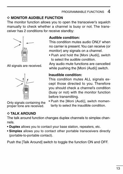
D MONITOR AUDIBLE FUNCTIONThe monitor function allows you to open the transceiver’s squelch manually to check whether a channel is busy or not. The trans-ceiver has 2 conditions for receive standby:
All signals are received.
Audible condition:This condition mutes audio ONLY when no carrier is present. You can receive (or monitor) any signals on a channel.• Push and hold the [Moni (Audi)], switch
to select the audible condition.Any audio mute functions are cancelled while pushing the [Moni (Audi)] switch.
Only signals containing the proper tone are received.
Inaudible condition:This condition mutes ALL signals ex-cept those directed to you. Therefore you should check a channel’s condition (busy or not) with the monitor function before transmitting.• Push the [Moni (Audi)], switch momen-
tarily to select the inaudible condition.
D TALK AROUNDThe talk around function changes duplex channels to simplex chan-nels.• Duplex allows you to contact your base station, repeaters, etc.• Simplex allows you to contact other portable transceivers directly
(portable-to-portable contact).
Push the [Talk Around] switch to toggle the function ON and OFF.

4 PROGRAMMABLE FUNCTIONS
14
D DTMF TRANSMISSIONThis function allows you to send a pre-programmed DTMF code to control a repeater, open another transceiver’s squelch, etc.
Manual transmission:Push desired digit keys in sequence while pushing [PTT].• Pushing [PTT] may not be necessary depending on programming.
Automatic pre-programmed transmission:q Push the [DTMF Autodial] switch to select DTMF autodial mode,
then push [CH Up] or [CH Down] to select the desired channel.w Push the [DTMF Autodial] switch to send a DTMF code.
D DTMF RE-DIAL FUNCTIONThis function allows you to transmit the last-used DTMF code at the push of a key.
Push the [Re-dial] switch momentarily to activate the function.• The previously transmitted DTMF code is automatically transmitted.• If no code has been transmitted since turning the power ON, this func-
tion does not activate.
D EMERGENCY FUNCTIONThe emergency function allows you to send an emergency signal quickly and easily to your base station, etc. in case of emergency.
Push and hold the [Emergency Single/Repeat] switch for 1 sec. to activate the emergency function.• The transceiver selects a pre-programmed channel, then sends an
emergency signal to your base station.• The pre-programmed channel remains selected until a control signal
is received from the base station, or power is turned OFF.• The emergency call is repeatedly transmitted at pre-programmed in-
tervals.

4PROGRAMMABLE FUNCTIONS
15
D DISPLAY LIGHTINGThe function display has 3 backlight conditions.ON : Backlight stays ON continuously. OFF : No backlight.AUTO : When any key is pushed, the backlight turns ON for 5
sec. automatically.

5 CONVENTIONAL OPERATION
16
n Receiving and transmitting NOTE: Transmitting without an antenna may damage the trans-ceiver. See p. 1 for antenna attachment. Turn power ON as described on p. 3.
Receiving:q Push [CH Up]/[CH Down], or rotate [SEL] to select a channel.w Listen for a transmission and adjust [VOL] to a comfortable lis-
tening level. • When no transmission is heard, push and hold monitor while ad-
justing [VOL] (your transceiver may not be programmed with the monitor function).
The transceiver is now set to receive desired calls on the selected channel.
Transmitting:Wait for the channel to become clear to avoid interference.q While pushing and holding [PTT], speak into the microphone at
a normal voice level. • When a tone signalling system is used, the call procedure de-
scribed at right may be necessary.w Release [PTT] to return to receive.
IMPORTANT: To maximize the readability of your transmitted sig-nal, pause a few seconds. After pushing [PTT], hold the microphone 5 to 10 cm from your mouth and speak at a normal voice level.

5CONVENTIONAL OPERATION
17
n Call procedureWhen your system employs tone signalling (excluding CTCSS and DTCS), the call procedure may be necessary prior to voice trans-mission. The tone signalling employed may be a selective calling system which allows you to call specific station(s) only and prevent unwanted stations from contacting you.
q Select the desired Tx code channel or 5-tone code according to your System Operator’s instructions.
• This may not be necessary depending on programming. • Refer to the next page for selection.w Push the call switch (assigned to one of the dealer program-
mable switches: [P0], [P1], [P2], [P3], [F2] and [F3]).e After transmitting a 5-tone code, the remainder of your commu-
nication can be carried out in the normal fashion.
Selective calling Non-selective calling

5 CONVENTIONAL OPERATION
18
n Tx code channel selectionYour radio may be programmed for Tx code channel selection. In this case, you can choose a Tx code channel to be transmitted when using the selective calling function (p. 17).
Push [Tx Code CH Up/Down] (assigned to one of the dealer-pro-grammable switches) to select the desired Tx code channel.• The selected code channel (containing a pre-programmed 5-tone
code) is transmitted when using the selective calling function.
n Manual 5-tone codesDepending on the programming, you may be able to send 5-tone codes manually.
Push [Tx Code] to activate the function, then enter the desired transmit code (up to 7 digits) using the keypad.• Activate the selective calling function to transmit the 5-tone code.• The digit to be edited blinks.
n Transmitting notes
D TIME-OUT TIMERAfter continuously transmitting past a pre-programmed time pe-riod, the time-out timer is activated, causing the transceiver to stop transmitting.
D PENALTY TIMEROnce the time-out timer is activated, transmission is further in-hibited for a period determined by the penalty timer.
6OTHER FUNCTIONS
19
n DTMF PAGER/CODE SQUELCH
D DTMF pagerThis function uses DTMF tones for calling and can be used as a “common pager” to inform you that one of your group has called even if the operator is temporarily away from the transceiver.• When the connection code is received, a beep sounds, then “ ”
flashes and shows the called station’s code number.• The called station’s code number is memorised automatically, and is easy to re-call with “ID-MR select function”.
D Code squelchThis conveniently eliminates unwanted audio and is useful in group activities or security related activities where unwanted output can be a problem. The function is similar to a CTCSS tone squelch.
In order to use the above functions, cloning is necessary via a PC using the optional CS-F30G cloning software. Using this software, the transceiver’s model, individual RX Code CH, TX Code CH, Special Tone Link2 (must be ‘E’) in 5Tone screen, 5Tone Signaling Form in Memory-CH screen, Log, RX C-No, Key&Display, Common Auto Reset Timer B, and other settings related to operation can be set. Refer to the HELP file that comes with the CS-F30G cloning software for available settings.
OPTIONAL UNIT INSTALLATION7
20
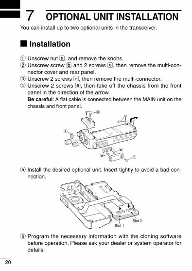
You can install up to two optional units in the transceiver.
n Installation
q Unscrew nut a, and remove the knobs.w Unscrew screw b and 2 screws c, then remove the multi-con-
nector cover and rear panel.e Unscrew 2 screws d, then remove the multi-connector. r Unscrew 2 screws e, then take off the chassis from the front
panel in the direction of the arrow. Be careful: A flat cable is connected between the MAIN unit on the
chassis and front panel.
a
bd
d
c
e
t Install the desired optional unit. Insert tightly to avoid a bad con-nection.
Slot 1Slot 2
y Program the necessary information with the cloning software before operation. Please ask your dealer or system operator for details.

8CLONING
21
n Cloning
Cloning allows you to quickly and easily transfer the programmed contents from one transceiver to another transceiver. Or, program data from a PC into a transceiver, using the optional CS-F30G cloning software.
D PC-to-transceiver cloningPlease refer to the HELP file that comes with the CS-F30G clon-ing software.
CAUTION: Improper cloning operation will cause a cloning error. In such a case, memory contents may be lost. Cloning must then be repeated.
9 OPTIONS
22
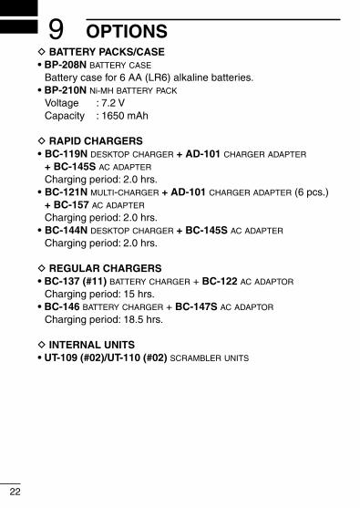
D BATTERY PACKS/CASE• BP-208N battery case
Battery case for 6 AA (LR6) alkaline batteries.• BP-210N Ni-MH battery pack
Voltage : 7.2 V Capacity : 1650 mAh
D RAPID CHARGERS• BC-119N desktop charger + AD-101 charger adapter
+ BC-145S ac adapter
Charging period: 2.0 hrs.• BC-121N multi-charger + AD-101 charger adapter (6 pcs.)
+ BC-157 ac adapter
Charging period: 2.0 hrs.• BC-144N desktop charger + BC-145S ac adapter
Charging period: 2.0 hrs.
D REGULAR CHARGERS• BC-137 (#11) battery charger + BC-122 ac adaptor
Charging period: 15 hrs.• BC-146 battery charger + BC-147S ac adaptor
Charging period: 18.5 hrs.
D INTERNAL UNITS• UT-109 (#02)/UT-110 (#02) scrambler units

D OTHER OPTIONS• EM-80/EM-89/HM-131SC speaker-microphones
• FA-SC12L/FA-SC13L flexible antennas
FA-SC12L: 66–76 MHzFA-SC13L: 76–88 MHz
• FA-SC56VS/FA-SC57VS/FA-SC73US stubby antennas
FA-SC56VS: 150–162 MHzFA-SC57VS: 160–174 MHzFA-SC73US: 450–490 MHz
• VS-1SC vox/ptt case + HS-94/HS-95/HS-97HS-94: Ear hook typeHS-95: Neck-arm typeHS-97: Throat microphone
• MB-103/MB-86 belt clips
MB-103 : Same as that supplied with the transceiver.MB-86 : Swivel belt clip
• MB-96N/MB-96F belt hangers
MB-96N : Swivel belt hanger.MB-96F : Standard type hanger.
• SP-13 earphone + AD-52 earphone jack adapter
• AD-98FSC antenna connector converter
Allows you to connect an external antenna with BNC connector.
Approved Icom optional equipment is designed for optimal perfor-mance when used with an Icom transceiver.Icom is not responsible for the destruction or damage to an Icom transceiver in the event the Icom transceiver is used with equip-ment that is not manufactured or approved by Icom.
Some options may not be available in some countries. Please ask your dealer for details.
23
9OPTIONS

CE Versions of the IC-F31GT/IC-F31GS, IC-F31GT-L/IC-F31GS-L, IC-F41GT/IC-F41GS which display the “CE” symbol on the serial num-ber label, comply with the essential requirements of the European Radio and Telecommunication Terminal Directive 1999/5/EC.
This warning symbol indicates that this equipment operates in non-harmonised frequency bands and/or may be subject to licensing conditions in the country of use. Be sure to check that you have the correct version of this radio or the correct program-ming of this radio, to comply with national licensing requirements.
• List of Country codes (ISO 3166-1)
Country Codes Country Codes
123456789
1011121314151617
AustriaBelgiumBulgariaCroatiaCzech RepublicCyprusDenmarkEstoniaFinlandFranceGermanyGreeceHungaryIcelandIrelandItalyLatvia
ATBEBGHRCZCYDKEEFIFRDEGRHUISIEITLV
18192021222324252627282930313233
LiechtensteinLithuaniaLuxembourgMaltaNetherlandsNorwayPolandPortugalRomaniaSlovakiaSloveniaSpainSwedenSwitzerlandTurkeyUnited Kingdom
LILTLUMTNLNOPLPTROSKSIESSECHTRGB
24
10 ABOUT CE

MEMO

MEMO

MEMO

1-1-32 Kamiminami, Hirano-ku, Osaka 547-0003, Japan
< Intended Country of Use >ATFIITPLGBRO
BEFRLVPTISTR
CYDELTSKLIHR
CZGRLUSINO
DKHUMTESCH
EEIENLSEBG
A-5672H-1EU-tPrinted in Japan© 2000–2009 Icom Inc.
Printed on recycled paper with soy ink.