via manzoni - gessi di montaggio/in_art_39212... · via manzoni. 2 caution - warning 1 - warning!!...
TRANSCRIPT

Gessi SpA - Parco Gessi 13037 Serravalle Sesia (Vercelli) - Italy
Phone +39 0163 454111 - Facsimile +39 0163 459273
www.gessi.com - [email protected]
BATH MIXING PROGRAMPROGRAMME DU MITIGEUR POUR LA SALLE DE BAIN
PROGRAMA MEZCLADORES BAÑO
Art. 39212VIA MANZONI

2
CAUTION - WARNING1 - WARNING!! PLEASE TAKE NOTICE THAT the suggested maximum pressure and/or temperature
MUST NEVER BE EXCEEDED, as it may damage and/or cause ruptures and/or leakages and/or even break the product, and present a potential hazard and danger to safety, health and/or property. Following are the technical data with respect to the installation of Gessi plumbing products.
►�Working�pressure�should�not�be�lower�than�0,5�bar�(7,25�psi)�and�not�be�higher�than�5�bar�(72�Psi).�In�case of higher working pressure use a pressure reducer valve.
►Maximum�test�installation�pressure:�8�bar�(116�psi).►�Avoid�major�pressure�differences�between�hot�and�cold�water�supply.�Differences�in�pressure,�water�
with high mineral content, and soapy substances can corrode the internal and external parts of the hoses and slowly weaken the materials thereby causing leakage.
►Maximum�working�temperature�for�Gessi�products�is�70°C�(158�°F).
2 - WARNING!! PLEASE TAKE NOTICE THAT the product should never be used as a tool, hammer or for any purposes other than the one it has been designed for.
3 - WARNING!! PLEASE TAKE NOTICE THAT the product should always be installed and tested by a professional plumber.
4 - WARNING!! For product installation, please refer to the LOCAL PLUMBING CODE.
5 - WARNING!! PLEASE TAKE NOTICE THAT electric cables should never be attached to the product as they may present a health and safety hazard.
6 - WARNING!!�PLEASE�TAKE�NOTICE�THAT�heavy�objects� should�never� be�placed�on�or� dropped�on the product as they may damage the same and cause splinters, which may present a health and safety hazard.
7 - WARNING!! PLEASE TAKE NOTICE THAT the instructions manual should carefully read before installation and the installation procedure provided therein must be properly followed and complied with.
8 - WARNING!! PLEASE TAKE NOTICE THAT during installation the use of excessive force should be avoided in order to prevent damage to the product and/or its components and pieces. NEVER force a component or piece into another. NEVER force screws or over tighten screws.
9 - WARNING!! No one uses aluminum FITTINGS for water connections.
3
ATTENTION - AVERTISSEMENT1 - ATTENTION!! NOUS VOUS PRIONS DE TENIR COMPTE QUE la pression et/ou la température
maximum suggérée NE DOIT JAMAIS ETRE DEPASSEE, car elle pourrait abîmer et/ou provoquer des ruptures et/ou des fuites et/ou des pannes du produit et, donc, représenter un risque et danger potentiel pour la sécurité, la santé et/ou les choses. Ci-dessous nous indiquons les données techniques concernant l’installation des produits sanitaires Gessi.
►�La�pression�de�service�ne�doit�pas�être�inférieure�à�0,5�bar�(7,25�psi)�et�supérieure�à�5�bar�(72�Psi).�En�cas de pressions de service plus hautes utiliser une soupape de réduction de la pression.
►Pression�maximum�d’essai�à�l’installation:�8�bar�(116�psi).►�Eviter�des�différences�de�pression�importantes�entre�l’alimentation�de�l’eau�chaude�et�celle�de�l’eau�
froide. Les différences de pression, l’eau avec une haute teneur minérale et les substances savonnées peuvent corroder les parties internes et externes des flexibles et, lentement, affaiblir les matières en provoquant des fuites.
►La�température�maximum�de�service�pour�les�produits�Gessi�est��70°C�(158�°F).
2 - ATTENTION!!�NOUS�VOUS�PRIONS�DE�TENIR�COMPTE�QUE�le�produit�ne�doit�jamais�être�utilisé�comme outil, marteau ou pour tout autre but, autre que celui pour lequel il a été conçu.
3 - ATTENTION!!�NOUS�VOUS�PRIONS�DE�TENIR�COMPTE�QUE�le�produit�doit�être�toujours�installé�et testé par un plombier professionnel.
4 - ATTENTION!! Pour l’installation du produit, référez-vous au LOCAL PLUMBING CODE, s.v.p.
5 - ATTENTION!! NOUS VOUS PRIONS DE TENIR COMPTE QUE les câbles électriques ne doivent jamais�être�reliés�au�produit�car�ils�pourraient�représenter�un�danger�pour�la�sécurité�et�la�santé.
6 - ATTENTION!!�NOUS�VOUS�PRIONS�DE�TENIR�COMPTE�QUE�les�objets�lourds�ne�doivent�jamais�être�posés�ou�fait�tomber�sur�le�produit,�car�il�peuvent�provoquer�la�projection�d’éclats�et�représenter�un danger pour la sécurité et la santé.
7 - ATTENTION!!�NOUS�VOUS�PRIONS�DE�TENIR�COMPTE�QUE� le�manuel�d’instructions�doit�être�lu� attentivement� avant� l’installation� et� que� les� procédures� d’installation� prévues� ici� doivent� être�adéquatement suivies et respectées.
8 - ATTENTION!! NOUS VOUS PRIONS DE TENIR COMPTE QUE, pendant l’installation, il faut éviter l’emploi�d’une�force�excessive�de�sorte�à�éviter�des�dommages�au�produit�et/ou�à�ses�composants�et�pièces.�NE�JAMAIS�forcer�un�composant�ou�une�pièce�à�l’intérieur�d’une�autre.�NE�JAMAIS�forcer�les�vis et ne pas les serrer excessivement.
9 - ATTENTION!! Ne pas utiliser raccords de aluminium pour les connexions de l’eau.
4
CUIDADO - ADVERTENCIA1 - ¡CUIDADO!! LES ROGAMOS QUE TENGAN EN CUENTA QUE NUNCA la presión y/o la temperatura
máxima�aconsejada�NO�TIENE�QUE�SER�SUPERADA,�ya�que�podría�dañar�y/o�causar�rupturas�y/o�pérdidas�y/o�averías�del�producto�y,�por�lo�tanto,�representar�un�riesgo�y�un�peligro�potencial�para�la seguridad, la saludad y/o la propiedad. A continuación Les proporcionamos los datos técnicos relativos�a�la�instalación�de�los�productos�de�grifería�Gessi.
►�La�presión�de�ejercicio�no�tiene�que�ser�inferior�a�0,5�bar�(7,25�psi)�y�superior�a�5�bar�(72�Psi).�En�caso�de�presiones�de�ejercicio�mayores,�utilicen�una�válvula�de�reducción�de�la�presión.
►Presión�máxima�de�ensayo�durante�la�instalación:�8�bar�(116�psi).►�Eviten�grandes�diferencias�de�presión�entre�la�alimentación�del�agua�fría�y�aquella�del�agua�caliente.�Las�diferencias�de�presión,�el�agua�con�una�lato�contenido�mineral�y�las�sustancias�jabonosas�pueden�corroer las partes interiores y exteriores de los flexos y, lentamente, e, lentamente, debilitar los materiales causando pérdidas.
►La�temperatura�máxima�de�ejercicio�para�los�productos�Gessi�es�70°C�(158�°F).
2 - ¡CUIDADO!! LES ROGAMOS QUE TENGAN EN CUENTA QUE nunca el producto no tiene que ser utilizado�como�en�lugar�de�herramienta,�martillos�o�para�finalidades�diferentes�de�aquellas�para�las�cuales�ha�sido�diseñado.
3 - ¡CUIDADO!! LES ROGAMOS QUE TENGAN EN CUENTA QUE el producto tiene que ser instalado y ensayado siempre por un fontanero profesional.
4 - ¡CUIDADO!! Para la instalación del producto Les rogamos que contacten con el LOCAL PLUMBING CODE.
5 - ¡CUIDADO!! LES ROGAMOS QUE TENGAN EN CUENTA QUE nunca los cables eléctricos no tiene que�ser�conectado�al�producto�ya�que�podrían�representar�un�peligro�para�la�seguridad�y�la�salud.
6 - ¡CUIDADO!!�LES�ROGAMOS�QUE�TENGAN�EN�CUENTA�QUE�nunca��objetos�pesados�no�tienen�que�ser�apoyados�o�dejados�caer�sobre�el�producto�ya�que�podrían�causar�la�proyección�de�astillas�y�representar un peligro para la seguridad y la salud.
7 - ¡CUIDADO!! LES ROGAMOS QUE TENGAN EN CUENTA QUE el manual de instrucción tiene que�ser� leído�con�cuidado�antes�de� la� instalación�y�que�hay�que�cumplir�adecuadamente�con� los�procedimientos de instalación proporcionados.
8 - ¡CUIDADO!! LES ROGAMOS QUE TENGAN EN CUENTA QUE, durante la instalación, hay que evitar el�uso�de�una�fuerza�excesiva�de�manera�que�se�puedan�evitar�daños�del�producto�y/o�componentes�y�piezas. NO fuercen NUNCA un componente o una pieza, la una dentro de la otra. NO fuercen NUNCA los tornillos y no los cierren excesivamente.
9 - ¡CUIDADO!! No utilicen ACCESORIOS de aluminio para las conexiones del agua.
5
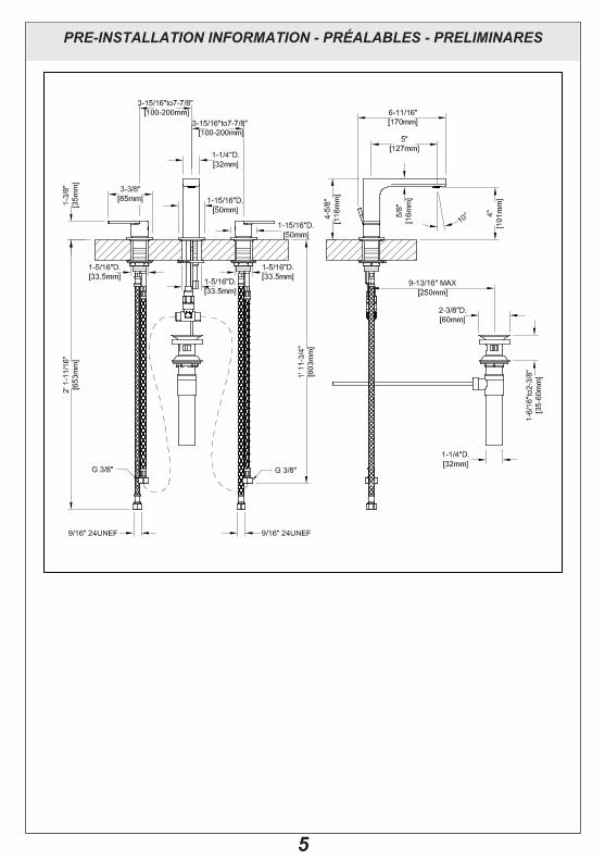
PRE-INSTALLATION INFORMATION - PRÉALABLES - PRELIMINARES
6
PRE-INSTALLATION INFORMATION - PRÉALABLES - PRELIMINARES
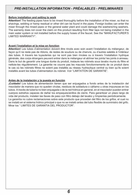
Before installation and setting to workAttention! The feeding pipes have to be rinsed thoroughly before the installation of the mixer, so that no shavings, welding or hemp residual or other dirt can be found in the pipes. Foreign bodies can enter the mixer through the rinsed pipes or the general water plant and could damage the washers/ring washers. The�warranty�does�not�cover�the�claim�on�this�product�resulting�from�filter�taps�not�being�installed�in�the�main water system or not installed before the supply hoses of the faucet. See the “MANUFACTURER’S LIMITED�WARRANTY”.�
Avant l’installation et la mise en fonctionAttention!�Les�tubes�d’alimentation�doivent�être�rincés�avec�soin�avant�l’installation�du�mélangeur,�de�façon�qu’il�ne�reste�pas�de�riblons,�de�restes�de�soudure�ou�de�chanvre,�ou�d’autres�saletés�à�l’intérieur�des� tubes.� A� travers� les� tuyauteries� qui� ne� sont� pas� bien� rincées� ou� à� travers� l’installation� hydrique�générale,�des�corps�étrangers�peuvent�entrer�dans�le�mélangeur�et�abîmer�les�joints/�les�joints�à�anneau.�Dans�le�but�de�garantir�une�longue�durée�du�produit,�instaure�les�robinets�sous�lavabo�munis�du�filtre�et�nettoie-les régulièrement. La garantie ne couvre pas les mauvais fonctionnements de ce produit dans le�cas�où�les�robinets�filtres�ne�soient�pas�installés�au�réseau�hydraulique�central�ou�bien�qu’ils�soient�installés avant les tubes d’alimentation du robinet. Voir “LIMITATION DE GARANTIE”.
Antes de la instalación y la puesta en función¡Cuidado! Los� tubos�de�alimentación� tienen�que�ser�enjuagados�a� fondo�antes�de� la� instalación�del�mezclador�de�manera�que�no�queden�virutas,�residuos�de�soldadura�o�cáñamo�u�otras�impurezas�en�los�tubos.�A�través�de�tubería�no�bien�enjuagada�o�de�la�red�hídrica�en�general,�en�el�mezclador�pueden�entrar�cuerpos�extraños�capaces�de�dañar�los�empaques/anillos�de�cierre.�Para�garantizar�un�plazo�largo�de�vida�del�producto,�instalen�las�llaves�de�paso�con�filtro�debajo�del�lavabo�y�límpienlas�periódicamente.�La�garantía�no�cubre�reclamaciones�sobre�este�producto�que�procedan�del�filtro�de�los�grifos,�el�cual�no�se�instalò�en�el�sistema�hídrico�principal�o�que�no�se�instalò�antes�del�tubo�flexible�de�suministro�del�grifo.�Mirar�los�“�LIMITES�DE�GARANTIA�DEL�PRODUCTOR”.
7
PRE-INSTALLATION INFORMATION - PRÉALABLES - PRELIMINARES
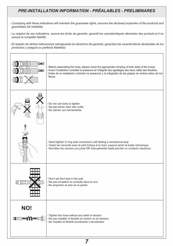
- Before assembling the hose, please check the appropriate crimping of both sides of the hoses.-�Avant�l’installation�contrôler�la�présence�et�l’intégrité�des�agrafages�des�deux�côtés�des�flexibles.- Antes de la instalación controlen la presencia y la integridad de las grapas en ambos lados de los flexos.
- Do not use tools to tighten. - Ne pas serrer avec des outils. - No cierren con herramienta.
- Hand-tighten O-ring seal connectors until feeling a mechanical stop.- �Visser�les�raccords�avec�le�joint�torique�à�la�main,�jusqu’á�sentir�la�butée�mécanique.-��Atornillen�los�racores�con�junta�OR�manualmente�hasta�percibir�un�contacto�mecánico.�
- Don’t set the hose in the wall.- Ne pas encastrer la conduite dans le mur.- No empotren el tubo en la pared.
- Tighten the hose without any twist or tension.-��Ne�pas�installer�le�flexible�en�torsion�ou�en�tension.-�No�instalen�el�flexible�torciéndolo�o�tensándolo.�
- Complying with these indications will maintain the guarantee rights, ensures the declared properties of the products and guarantees full reliability.
- Le respect de ces indications, assure les droits de garantie, garantit les caractéristiques déclarées des produits et il en assure la complète fiabilité.
- El respeto de dichas indicaciones salvaguarda los derechos de garantía, garantiza las características declaradas de los productos y asegura su perfecta fiabilidad.
2 x Ø
OK!
OK!
2 x Ø
OK!
OK!
NO!
8
PRE-INSTALLATION INFORMATION - PRÉALABLES - PRELIMINARES
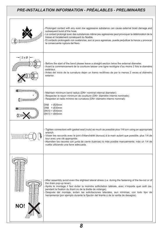
- Prolonged contact with any even low aggressive substance can cause external braid damage and subsequent burst of the hose.-��Le�contact�prolongé�avec�des�substances�même�peu�agressives�peut�provoquer�la�détérioration�de�la�tresse�et�l’éclatement�conséquent�du�flexible.-��El�contacto�prolongado�con�sustancias,�aun�si�poco�agresivas,�puede�perjudicar�la�trenza�y�provocar�la�consecuente�ruptura�del�flexo.�
- Before the start of the bend please leave a straight section twice the external diameter.-��Avant�le�commencement�de�la�courbure�laisser�une�ligne�rectiligne�d’au�moins�2�fois�le�diamètre�extérieur.-��Antes�del�inicio�de�la�curvatura�dejen�un�tramo�rectilíneo�de�por�lo�menos�2�veces�el�diámetro�exterior.
-�Maintain�minimum�bend�radius�(DN=�nominal�internal�diameter):-�Respecter�le�rayon�minimum�de�courbure�(DN=�diamètre�interne�nominale):�-�Respeten�el�radio�mínimo�de�curvatura�(DN=�diámetro�interno�nominal):
DN6���=�Ø25mm�DN8���=�Ø30mm�DN10�=�Ø35mm�DN13�=�Ø45mm�
-��Tighten�connectors�with�gasket�seal�(nuts)�as�much�as�possible�plus�1/4�turn�using�an�appropriate�wrench.
-���Visser�les�raccords�avec�le�joint�d’étanchéité�(écrous)�à�la�main�autant�que�possible,�plus�1/4�de�tour avec une clé appropriée.
-��Atornillen�los�racores�con�junta�de�cierre�(tuercas)�lo�más�posible�manualmente,�más�un�1/4�de�vuelta utilizando una llave adecuada.
-��After�assembly�avoid�even�the�slightest�lateral�stress�(i.e.�during�the�fastening�of�the�tie-rod�or�of�the�drain�pop-up�lever).-��Après� le�montage� il� faut� éviter� la�moindre� sollicitation� latérale,� avec� n’importe� quel� outil� (ex.�pendant�la�fixation�du�tirant�ou�de�la�tirette�de�vidange).-��Después� del� montaje,� eviten� las� solicitaciones� laterales,� aun� mínimas,� con� todo� tipo� de�herramienta�(por�ejemplo�durante�la�fijación�del�tirante�o�de�la�varilla�de�desagüe).
2 x Ø
OK!
OK!
2 x Ø
OK!
OK!
NO!
9
PRE-INSTALLATION INFORMATION - PRÉALABLES - PRELIMINARES
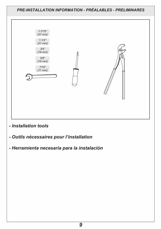
- Installation tools
- Outils nécessaires pour l’installation
- Herramienta necesaria para la instalación
7/16”[11 mm]
5/8”[16 mm]
1-7/16”[37 mm]
1-1/4”[31 mm]
3/4”[19 mm]

10
PRE-INSTALLATION INFORMATION - PRÉALABLES - PRELIMINARES
Before�the�installation�to�screw�the�supply�flexible�tubes�to�the�controls�and�install�the�pop-up�waste rod on the body of the spout.
Avant�de�l’�installation�visser�les�tubes�flexible�d’�alimentation�aux�commandes�et�installer la tige de contrôle de l’écoulement.
Antes�de�la�instalaciòn�atornillar�los�tubos�flexibles�de�alimentaciòn�a�los�mandos�y�Instalen el asta de controle de descarga.
Fig. 1 Fig. 2
11
INSTALLATION - INSTALLATION - INSTALACIÓN
Fig. 3
Fig. 4
< 11/16“[17mm]
X < 11/16“[17mm]
X
7/16”[11 mm]
1-1/4”[31 mm]
1-1/4”[31 mm]
12
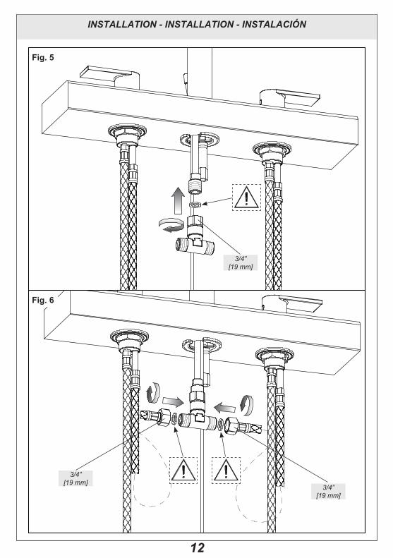
INSTALLATION - INSTALLATION - INSTALACIÓN
Fig. 5
Fig. 6
3/4”[19 mm]
3/4”[19 mm]
3/4”[19 mm]
13
INSTALLATION - INSTALLATION - INSTALACIÓN
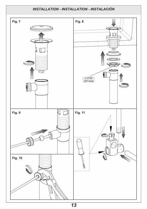
Fig. 7 Fig. 8
Fig. 9 Fig. 11
Fig. 10
1-7/16”[37 mm]
14
INSTALLATION - INSTALLATION - INSTALACIÓN
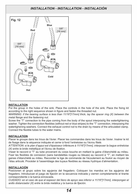
Fig. 12
Hot
Cold
Red
Blue
5/8”[16 mm]
5/8”[16 mm]
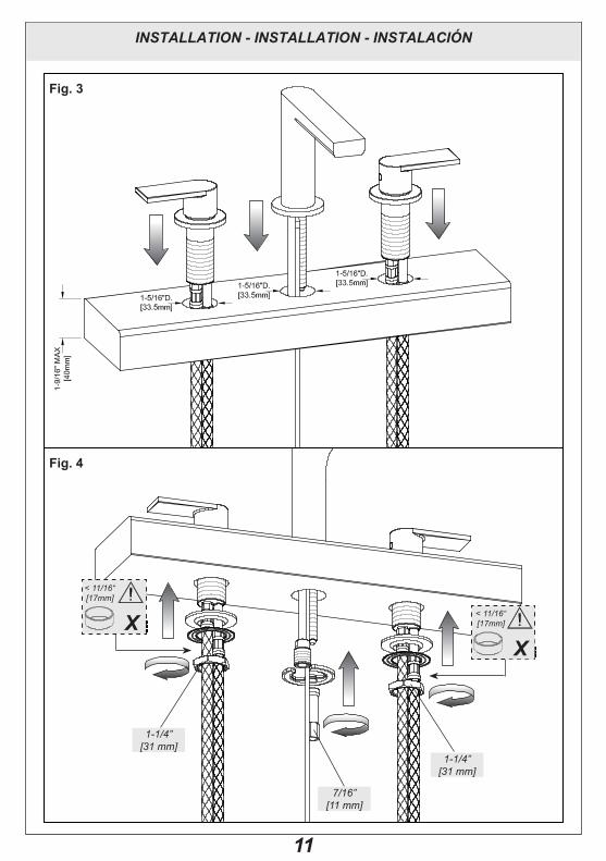
INSTALLATIONPut� the�group� in� the�holes�of� the� sink.�Place� the� controls� in� the�hole�of� the� sink.�Place� the� fixing� kit�according�to�the�right�sequence�shown�in�figure�and�fasten�the�threaded�nut.WARNING: if the bearing surface is less than 11/16"[17mm] thick, lay the spacer ring (X) between the metal flange and the fastening nut. Screw�the�“T”�connection�to�the�pipe�coming�from�the�body�of�the�spout�interposing�the�watertightening�washer.�Tighten�the�connection�flexibles�(without�red�or�blue�stripes)�to�the�“T”�connection,�interposing�the�watertighening washers. Connect the exhaust control rod to the drain by means of the articulated clamp. Connect�the�flexible�tubes�to�the�water�mains.
INSTALLATIONPlacer le groupe dans les trous de l’évier. Placer les commandes dans les trous de l’évier. Insérer le kit de�fixage�dans�la�séquence�indiquée�et�cerrer�à�fond�l’entretoise�ou�l’écrou�fileté.ATTENTION: si le plan d’appui est d’épaisseur inférieure à 11/16"[17mm], interposer la bague entretoise (X) entre la bride métallique et l’écrou de fixation. Visser�le�raccord�à�“T”�au�tube�provenant�du�corps�bouche�en�mettant�la�gaine�d’étanchéité�au�milieu.�Fixer�les�flexibles�de�connexion (sans�bandelettes�rouges�ou�bleues)�au�raccord�à�“T”,�en�mettant� les�gaines d’étanchéité au milieu. Raccorder la tige de commande de l’écoulement au fouloir au moyen de l’étau�articulé.�Procéder�à�l’assemblage�des�tuyaux�flexibles�au�réseau�hydrique�d’alimentation.
INSTALLACIÓNPosicionen� el� grupo� sobre� los� agujeros� del� fregadero.� Coloquen� los� mandos� en� los� agujeros� del�fregadero.�Introduzcan�el�juego�de�fijación�en�la�secuencia�indicada�y�cierren�completamente�el�tirante�correspondiente o la tuerca enroscada.CUIDADO: en el caso de que el espesor del llano de apoyo sea inferior a 11/16"[17mm], interpongan el anillo distanciador (X) entre la brida metálica y la tuerca de fijación.

15
INSTALLATION - INSTALLATION - INSTALACIÓN
Atornillen� el� racor� en� “T”� al� tubo� que� procede� del� cuerpo� del� caño� interponiendo� la� junta� de� cierre.�Fijen� los�flexibles�de�conexión (sin�cintas� rojas�o�azules)�al� racor�en� “T”,� interponiendo� las� juntas�de�cierre. Conecten�la�varilla�de�mando�del�desagüe�a�la�válvula�mediante�el�enganche�articulado.�Sigan�la�conexión�de�los�flexibles�a�la�red�hídrica�de�alimentación.
16
WORkING - FONCTIONNEMENT - FUNCIONAMIENTO
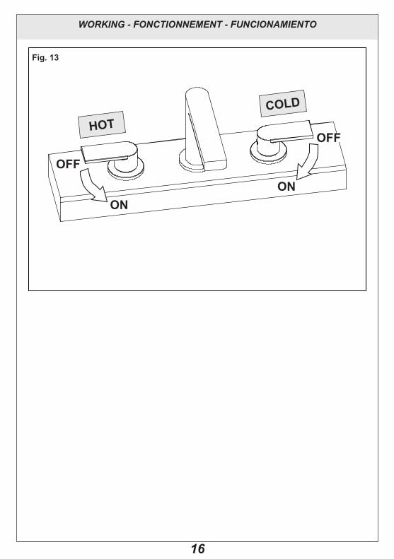
Fig. 13
OFF
ON
HOTCOLD
ON
OFF
17
MAINTENANCE - ENTRETIEN - MANUTENCIÓN
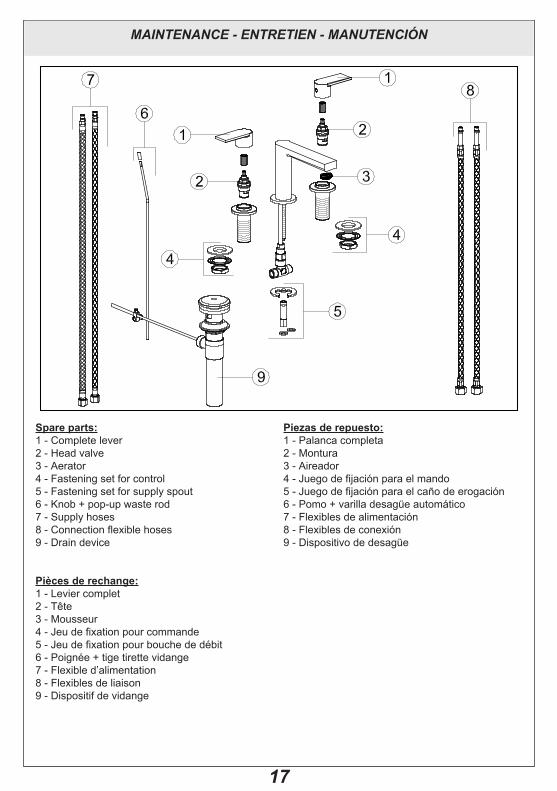
Spare parts:1�-�Complete�lever2�-�Head�valve3�-�Aerator4�-�Fastening�set�for�control5�-�Fastening�set�for�supply�spout6�-�Knob�+�pop-up�waste�rod7�-�Supply�hoses8�-�Connection�flexible�hoses9 - Drain device
Pièces de rechange:1�-�Levier�complet2�-�Tête3�-�Mousseur4�-�Jeu�de�fixation�pour�commande5�-�Jeu�de�fixation�pour�bouche�de�débit6�-�Poignée�+�tige�tirette�vidange7�-�Flexible�d’alimentation8�-�Flexibles�de�liaison9 - Dispositif de vidange
Piezas de repuesto:1�-�Palanca�completa2�-�Montura3�-�Aireador4�-�Juego�de�fijación�para�el�mando5�-�Juego�de�fijación�para�el�caño�de�erogación6�-�Pomo�+�varilla�desagüe�automático7�-�Flexibles�de�alimentación8�-�Flexibles�de�conexión9�-�Dispositivo�de�desagüe
18
MAINTENANCE - ENTRETIEN - MANUTENCIÓN
Fig. 14 Fig. 15
AB
C
D
E
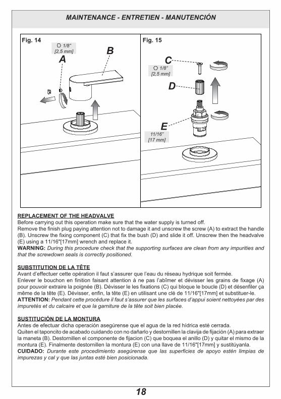
REPLACEMENT OF THE HEADVALVE Before carrying out this operation make sure that the water supply is turned off.Remove�the�finish�plug�paying�attention�not�to�damage�it�and�unscrew�the�screw�(A)�to�extract�the�handle�(B).�Unscrew�the�fixing�component�(C)�that�fix�the�bush�(D)�and�slide�it�off.�Unscrew�then�the�headvalve�(E)�using�a�11/16"[17mm] wrench and replace it. WARNING: During this procedure check that the supporting surfaces are clean from any impurities and that the screwdown seals is correctly positioned.
SUBSTITUTION DE LA TÊTEAvant d’effectuer cette opération il faut s’assurer que l’eau du réseau hydrique soit fermée.Enlever� le�bouchon�en� finition� faisant�attention�à�ne�pas� l’abîmer�et�dévisser� les�grains�de� fixage� (A)�pour�pouvoir�extraire�la�poignée�(B).�Dévisser�le�les�fixations�(C)�qui�bloque�le�boucle�(D)�et�désenfiler�ça�même�de�la�tête�(E).�Dévisser,�enfin,�la�tête�(E)�en�utilisant�une�clé�de�11/16"[17mm] et substituer-le.ATTENTION: Pendant cette procédure il faut s’assurer que les surfaces d’appui soient nettoyées par des impuretés et du calcaire et que la garniture de la tête soit bien placée.
SUSTITUCIÓN DE LA MONTURAAntes�de�efectuar�dicha�operación�asegúrense�que�el�agua�de�la�red�hídrica�esté�cerrada.Quiten�el�taponcito�de�acabado�cuidando�con�no�dañarlo�y�destornillen�la�clavija�de�fijación�(A)�para�extraer�la�maneta�(B).�Destornillen�el�componente�de�fijacion�(C)�que�boquea�el�anillo�(D)�y�quitar�el�mismo�de�la�montura�(E).�Finalmente�destornillen�la�montura�(E)�con�una�llave�de�11/16"[17mm] y sustitúyanla. CUIDADO: Durante este procedimiento asegúrense que las superficies de apoyo estén limpias de impurezas y cal y que las juntas esté bien posicionada.
1/8”[2,5 mm]
1/8”[2,5 mm]
11/16”[17 mm]
19
MAINTENANCE - ENTRETIEN - MANUTENCIÓN
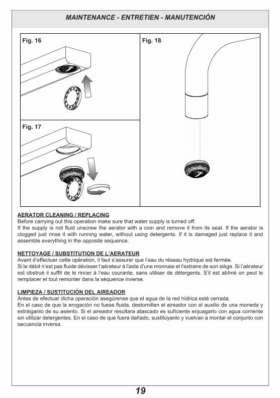
AERATOR CLEANING / REPLACINGBefore carrying out this operation make sure that water supply is turned off.If� the�supply� is�not�fluid�unscrew� the�aerator�with�a�coin�and� remove� it� from� its�seat.� If� the�aerator� is�clogged� just� rinse� it�with� running�water,�without�using�detergents.� If� it� is�damaged� just� replace� it�and�assemble everything in the opposite sequence.
NETTOYAGE / SUBSTITUTION DE L’AERATEURAvant d’effectuer cette opération, il faut s’assurer que l’eau du réseau hydrique est fermée.Si�le�débit�n’est�pas�fluide�dévisser�l’aérateur�à�l'aide d'une monnaie et l'extraire de son siège. Si l’aérateur est�obstrué� il�suffit�de� le�rincer�à� l’eau�courante,�sans�utiliser�de�détergents.�S’il�est�abîmé�on�peut� le�remplacer et tout remonter dans la séquence inverse.
LIMPIEZA / SUSTITUCIÓN DEL AIREADORAntes�de�efectuar�dicha�operación�asegúrense�que�el�agua�de�la�red�hídrica�esté�cerrada.En�el�caso�de�que�la�erogación�no�fuese�fluida,�destornillen�el�aireador�con�el�auxilio�de�una�moneda�y�extráiganlo�de�su�asiento.�Si�el�aireador�resultara�atascado�es�suficiente�enjuagarlo�con�agua�corriente�sin�utilizar�detergentes.�En�el�caso�de�que�fuera�dañado,�sustitúyanlo�y�vuelvan�a�montar�el�conjunto�con�secuencia inversa.
Fig. 16 Fig. 18
Fig. 17
20
MAINTENANCE - ENTRETIEN - MANUTENCIÓN
MIXER CLEANINGWater�contains�limestone�in�different�qualities,�which�remains�kept�on�the�surfaces�of�the�product,�leaving�deposits after the water has been evaporated. It is possible to prevent the forming of limestone deposits and to keep your product clean by drying it always with a soft cloth immediately after use. DETERGENTS, SOLVENTS,�CHEMICAL�AGENTS,�ABRASIVE�SPONGES,�WIRE�WOOL,�ALCOHOL,�ETC.�SHOULD�NOT BE USED as these could irreparably damage products’ surfaces compromising their aesthetics, brightness�and�satinizing.�CLEAN�EXCLUSIVELY�WITH�WATER�AND�SOAP�DRYING�THEM�WITH�A�SOFT�CLOTH.�Clean�regularly�the�aerator�filter�after�having�it�disassembled�and�after�having�removed�the�limestone�which�obstructs�the�outlets.�When�using�spray�soap,�splash�first�on�a�clean�cloth�or�on�a�sponge, NEVER directly on the product.
NETTOYAGE DU MÉLANGEURL’eau contenant du calcaire en quantité variable, celui-ci après évaporation se retrouve en dépôt sur le matériau�de�finition.� Il�est�possible�d’éviter�un�tel�dépôt,�en�essuyant� la�surface�avec�un�chiffon�doux,�après utilisation. L’UTILISATION DE DETERGENTS, SOLVANTS, AGENTS CHIMIQUES, EPONGES ABRASIVES, PAILLE METALLIQUE, ALCOOL, ETC. SONT INTERDITS au risque de détériorer irrémédiablement� la� finition� du� produit,� en� compromettant� l’esthétique,� la� brillance� et� le� satinage.�NETTOYAGE� EXCLUSIF� A� L’EAU� ET� AU� SAVON,� EN� ESSUYANT� AVEC� UN� CHIFFON� DOUX.�Nettoyer� régulièrement� le� filtre� de� l’aérateur,� après� l’avoir� démonté� avec�précaution,� pour� éliminer� le�calcaire qui en obstrue la grille. En cas d’utilsation de savon en spray, NE JAMAIS vaporiser directement sur le produit mais sur un chiffon.
LIMPIEZA DEL MEZCLADOREl�agua�contiene�cal�en�cantidades�variables,�el�cual�queda�en�la�superficie�del�producto,�dejando�unos�sedimentos después de la evaporación del agua. Es posible prevenir las formaciones de sedimentos de cal y mantener el producto limpio, secándolo, inmediatamente después del uso, con un trapo. NO TIENEN QUE SER UTILIZADOS DETERGENTES, DISOLVENTES, AGENTES QUÍMICOS, ESPONJAS ABRASIVAS�O�METÁLICAS,�ALCOHOL,�ETC.�que�perjudicarían�irremediablemente�las�superficies�del�productos, comprometiendo su estética, su brillo y el satinado. LIMPIEN EXCLUSIVAMENTE CON AGUA�Y�JABÓN�SECANDO�CON�UN�TRAPO�SUAVE.�Limpien�periódicamente�el�filtro�del�aireador�tras�haberlo desmontado y eliminado los sedimentos de cal que obstruyen las salidas. En el caso de que se utilice�jabón�spray,�pulverícenlo�antes�sobre�un�trapo�limpio�o�sobre�una�esponja,�NUNCA�directamente�sobre el producto.
ET�42507�-�R0