video communication system - sony · video communication system version 2.10 software upgrade...
TRANSCRIPT

PCS-G50Video Communication System
Version 2.10Software Upgrade
Release Notes

CONFIDENTIAL
The material in this manual consists of information that is the property of SonyElectronics Inc. and is intended for use by the purchasers of the equipmentdescribed in this manual. Sony Electronics Inc. expressly prohibits theduplication of any portion of this manual or the use thereof for any purposeother than the operation or maintenance of the equipment described in thismanual without the express written permission of Sony Electronics Inc.
The software described herein may also be governed by the terms of aseparate end user license agreement.
Printed in USA
October 2005
©2005 Sony Electronics Inc.
Broadcast & Business Solutions Company
3300 Zanker Road, San Jose, CA 95134

Table of Contents
1. NEW FEATURES . . . . . . . . . . . . . . . . . . . . . . . . . . . . . . . . . . . . . . . . . . . . . . . . . . 1
1-1. Version 2.10. . . . . . . . . . . . . . . . . . . . . . . . . . . . . . . . . . . . . . . . . . . . . . . 1
1-1-1. Standard Encryption . . . . . . . . . . . . . . . . . . . . . . . . . . . . . . . . . . .11-1-2. PRI. . . . . . . . . . . . . . . . . . . . . . . . . . . . . . . . . . . . . . . . . . . . . . .21-1-3. Streaming . . . . . . . . . . . . . . . . . . . . . . . . . . . . . . . . . . . . . . . . . .21-1-4. TOS in LAN Settings . . . . . . . . . . . . . . . . . . . . . . . . . . . . . . . . . . .21-1-5. UPnP . . . . . . . . . . . . . . . . . . . . . . . . . . . . . . . . . . . . . . . . . . . . .31-1-6. Terminal Information Displayed on Launcher . . . . . . . . . . . . . . . . . .31-1-7. New Service Command . . . . . . . . . . . . . . . . . . . . . . . . . . . . . . . . .31-1-8. New SIP Functions . . . . . . . . . . . . . . . . . . . . . . . . . . . . . . . . . . . .4
2. PROGRAM IMPROVEMENTS . . . . . . . . . . . . . . . . . . . . . . . . . . . . . . . . . . . . . . . . . 5
2-1. Version 2.10. . . . . . . . . . . . . . . . . . . . . . . . . . . . . . . . . . . . . . . . . . . . . . . 5
2-1-1. Fine Tuning Camera Angle. . . . . . . . . . . . . . . . . . . . . . . . . . . . . . .52-1-2. Transmission of Presentation Data . . . . . . . . . . . . . . . . . . . . . . . . .52-1-3. H.263 4CIF . . . . . . . . . . . . . . . . . . . . . . . . . . . . . . . . . . . . . . . . .52-1-4. Web Interface . . . . . . . . . . . . . . . . . . . . . . . . . . . . . . . . . . . . . . .52-1-5. User Interface . . . . . . . . . . . . . . . . . . . . . . . . . . . . . . . . . . . . . . .62-1-6. Muting During DTMF Tone . . . . . . . . . . . . . . . . . . . . . . . . . . . . . . .62-1-7. Standby Mode . . . . . . . . . . . . . . . . . . . . . . . . . . . . . . . . . . . . . . .62-1-8. Bit Rate for ARC Video . . . . . . . . . . . . . . . . . . . . . . . . . . . . . . . . .62-1-9. Camera Control Target . . . . . . . . . . . . . . . . . . . . . . . . . . . . . . . . .6
2-1-10. Setup Data . . . . . . . . . . . . . . . . . . . . . . . . . . . . . . . . . . . . . . . . .62-1-11. Enabling or Disabling Connection-Related Settings . . . . . . . . . . . . . .62-1-12. Miscellaneous Improvements. . . . . . . . . . . . . . . . . . . . . . . . . . . . .62-1-13. Known Issues . . . . . . . . . . . . . . . . . . . . . . . . . . . . . . . . . . . . . . .7
2-2. Version 2.01. . . . . . . . . . . . . . . . . . . . . . . . . . . . . . . . . . . . . . . . . . . . . . . 7
2-2-1. Presentation Data . . . . . . . . . . . . . . . . . . . . . . . . . . . . . . . . . . . .7
3. OPERATION NOTES . . . . . . . . . . . . . . . . . . . . . . . . . . . . . . . . . . . . . . . . . . . . . . . 8
3-1. Documents Available . . . . . . . . . . . . . . . . . . . . . . . . . . . . . . . . . . . . . . . . 8
3-2. Memory Stick Required for Upgrade . . . . . . . . . . . . . . . . . . . . . . . . . . . . 8
3-3. Compatibility with Memory Stick Pro (1 GB) . . . . . . . . . . . . . . . . . . . . . . 8
3-4. LAN Encryption Compatibility . . . . . . . . . . . . . . . . . . . . . . . . . . . . . . . . . 8
3-5. Object Camera . . . . . . . . . . . . . . . . . . . . . . . . . . . . . . . . . . . . . . . . . . . . . 8
3-6. AUTO Video Mode. . . . . . . . . . . . . . . . . . . . . . . . . . . . . . . . . . . . . . . . . . . 8
3-7. Input of Far-End Terminal . . . . . . . . . . . . . . . . . . . . . . . . . . . . . . . . . . . . 9
i

3-8. Recommended Settings for Active-Motion Conferencing . . . . . . . . . . . . 9
3-9. Bit rate for QoS Forward Error Correction (FEC) . . . . . . . . . . . . . . . . . . 12
3-10. Destination for Saving/Reading Files on Memory Stick . . . . . . . . . . . . 13
3-11. Number of Lines and Points in ISDN Multipoint Conference . . . . . . . . . 13
3-12. Service Commands. . . . . . . . . . . . . . . . . . . . . . . . . . . . . . . . . . . . . . . . . 14
3-12-1. How to Use Service Commands . . . . . . . . . . . . . . . . . . . . . . . . . .143-12-2. Service Command List . . . . . . . . . . . . . . . . . . . . . . . . . . . . . . . .15
3-13. Keyboard Shortcuts . . . . . . . . . . . . . . . . . . . . . . . . . . . . . . . . . . . . . . . . 17
4. INTEROPERABILITY . . . . . . . . . . . . . . . . . . . . . . . . . . . . . . . . . . . . . . . . . . . . . 18
4-1. H.320 Endpoint . . . . . . . . . . . . . . . . . . . . . . . . . . . . . . . . . . . . . . . . . . . 18
4-2. H.323 Endpoint . . . . . . . . . . . . . . . . . . . . . . . . . . . . . . . . . . . . . . . . . . . 19
4-3. Miscellaneous Terminals . . . . . . . . . . . . . . . . . . . . . . . . . . . . . . . . . . . . 21
5. VERSION HISTORY . . . . . . . . . . . . . . . . . . . . . . . . . . . . . . . . . . . . . . . . . . . . . . 22
ii
PCS-G50 Video Communication System
1. NEW FEATURES
1-1. Version 2.10
1-1-1. Standard Encryption
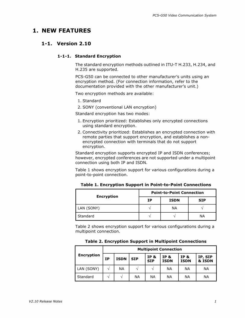
The standard encryption methods outlined in ITU-T H.233, H.234, and H.235 are supported.
PCS-G50 can be connected to other manufacturer’s units using an encryption method. (For connection information, refer to the documentation provided with the other manufacturer’s unit.)
Two encryption methods are available:
1. Standard
2. SONY (conventional LAN encryption)
Standard encryption has two modes:
1. Encryption prioritized: Establishes only encrypted connections using standard encryption.
2. Connectivity prioritized: Establishes an encrypted connection with remote parties that support encryption, and establishes a non-encrypted connection with terminals that do not support encryption.
Standard encryption supports encrypted IP and ISDN conferences; however, encrypted conferences are not supported under a multipoint connection using both IP and ISDN.
Table 1 shows encryption support for various configurations during a point-to-point connection.
Table 2 shows encryption support for various configurations during a multipoint connection.
Table 1. Encryption Support in Point-to-Point Connections
EncryptionPoint-to-Point Connection
IP ISDN SIP
LAN (SONY) √ NA √
Standard √ √ NA
Table 2. Encryption Support in Multipoint Connections
Encryption
Multipoint Connection
IP ISDN SIP IP & SIP
IP & ISDN
IP & ISDN
IP, SIP & ISDN
LAN (SONY) √ NA √ √ NA NA NA
Standard √ √ NA NA NA NA NA
V2.10 Release Notes 1

PCS-G50 Video Communication System
The following restrictions apply to the standard encryption function:
• ISDN connection: Standard encryption is not supported with a non-bonding connection. Use standard encryption with a bonding connection.
• IP connection: The maximum bit rate is 2 Mbps.
1-1-2. PRI
ISDN PRI I/F (PCSA-PRI) is supported.
1-1-3. Streaming
Streaming of video and audio signals on a network is supported.
Streaming is supported regardless of whether or not conferencing is in progress and regardless of the conference configuration (ISDN, LAN, point-to-point, multipoint).
The following settings can be selected for video signals with MPEG4:
Not specified64 Kbps128 Kbps256 Kbps 512 Kbps
Audio signals are fixed to 64 Kbps with MPEG4 AAC.
The recommended reception environments are:
Windows XPWindows Explorer 6.XQuickTime 6.X
1-1-4. TOS in LAN Settings
TOS (TypeOfService) in LAN settings can be set to the following types of transmission data:
Audio
Video
Remote camera control information
DSB data
NOTE: When the system is upgraded, the video setting must be copied to the audio, camera control and DSB data settings.
2 V2.10 Release Notes

PCS-G50 Video Communication System
1-1-5. UPnP
To support UPnP, the Auto setting is added to NAT in the LAN settings. The Auto setting automatically starts negotiations with the router, then automatically registers the information necessary for NAT.
The routers in Table 3 are compatible with V2.10 software.
The following routers are also compatible with V2.10 software (using the most recent firmware version for each router).
I/O Data NP-BBRM
NTT-West Web Caster 710
YAMAHA RT57
1-1-6. Terminal Information Displayed on Launcher
The following terminal information can be displayed on the launcher screen:
GK user number
GK user name
NAT address
IP address
Do not display
SIP registered user name (Optional PCSA-SP1 software is required.)
SIP address (Optional PCSA-SP1 software is required.)
1-1-7. New Service Command
PKS**** Defines video packet size, where **** represents values from 0000 to 9999.
NOTE: Refer to “How to Use Service Commands” on page 14.
Table 3. Supported UPnP Routers/Gateways
MFG Model HW Version Firmware Out
CallH.239 OUT IN In
CallH.239
IN OUT
Netgear WGR614 V4 V5.0_07 OK OK OK OK OK OK
Netgear RP614 V3 V.60 OK OK OK OK OK OK
Dlink DI524 C1 3.02 OK OK OK FAIL — —
Dlink DI624 C3 2.5 FAIL OK FAIL FAIL — —
Belkin F5D7230-4 2000 4.05.03 OK OK OK FAIL — —
Buffalo WBR2-G45S None 2.3 OK OK OK OK OK OK
Linksys WRT54G V2.2 3.03.6 OK OK OK OK OK OK
USR USR8054 None V1.67b44 OK OK OK OK OK OK
SMC 7994VWBR None V1.00.014 OK OK OK FAIL — —
V2.10 Release Notes 3
PCS-G50 Video Communication System
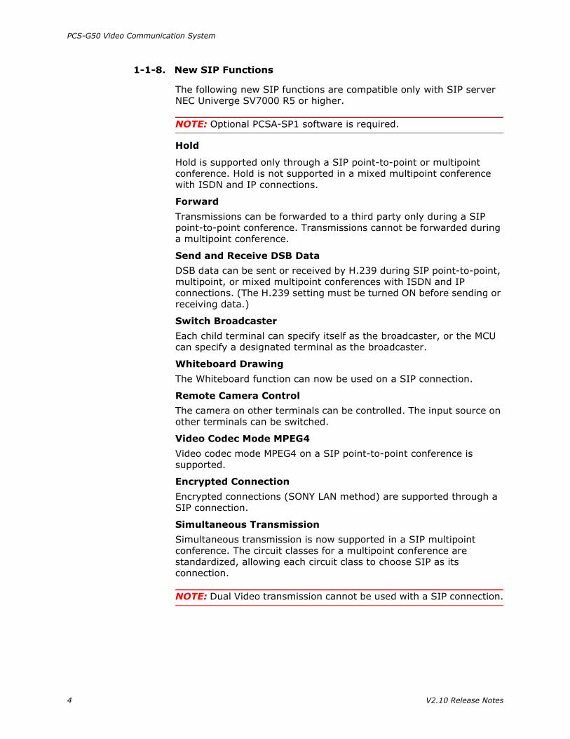
1-1-8. New SIP Functions
The following new SIP functions are compatible only with SIP server NEC Univerge SV7000 R5 or higher.
NOTE: Optional PCSA-SP1 software is required.
Hold
Hold is supported only through a SIP point-to-point or multipoint conference. Hold is not supported in a mixed multipoint conference with ISDN and IP connections.
Forward
Transmissions can be forwarded to a third party only during a SIP point-to-point conference. Transmissions cannot be forwarded during a multipoint conference.
Send and Receive DSB Data
DSB data can be sent or received by H.239 during SIP point-to-point, multipoint, or mixed multipoint conferences with ISDN and IP connections. (The H.239 setting must be turned ON before sending or receiving data.)
Switch Broadcaster
Each child terminal can specify itself as the broadcaster, or the MCU can specify a designated terminal as the broadcaster.
Whiteboard Drawing
The Whiteboard function can now be used on a SIP connection.
Remote Camera Control
The camera on other terminals can be controlled. The input source on other terminals can be switched.
Video Codec Mode MPEG4
Video codec mode MPEG4 on a SIP point-to-point conference is supported.
Encrypted Connection
Encrypted connections (SONY LAN method) are supported through a SIP connection.
Simultaneous Transmission
Simultaneous transmission is now supported in a SIP multipoint conference. The circuit classes for a multipoint conference are standardized, allowing each circuit class to choose SIP as its connection.
NOTE: Dual Video transmission cannot be used with a SIP connection.
4 V2.10 Release Notes

PCS-G50 Video Communication System
2. PROGRAM IMPROVEMENTS
2-1. Version 2.10
2-1-1. Fine Tuning Camera Angle
Camera angle can be fine tuned. When first pressing the arrow button on the remote commander, the camera moves slowly; as the button is held, the camera moves faster.
2-1-2. Transmission of Presentation Data
The time required to transmit presentation data via DSB is reduced.
2-1-3. H.263 4CIF
The performance of video mode (H.263 4CIF) is improved.
2-1-4. Web Interface
The Web interface is improved as follows:
• Web control is now available to users who want to release streamed data that has been received.
• The MIC Off indicator is displayed on the terminal.
• To avoid confusion as to which terminal is in control, the terminal name is displayed in the Web control window. (See Figure 1.)
Figure 1
V2.10 Release Notes 5

PCS-G50 Video Communication System
2-1-5. User Interface
The user interface is improved as follows:
• A confirmation dialog box now appears when recording is ended.
• Invalid multicast addresses can no longer be saved (224.0.0.0-239.255.255.255).
• Files recorded on a memory stick now appear in a list on the Memory Stick menu.
• The “broadcast in progress” indicator is animated during a multipoint conference. When the indicator is terminated, the indicator shrinks and fades.
2-1-6. Muting During DTMF Tone
Audio from MIC/AUX-IN is now muted during DTMF tone transmission.
2-1-7. Standby Mode
The unit can be released from standby mode by pressing any button on the remote control (other than the Power On button).
2-1-8. Bit Rate for ARC Video
In an environment with significant packet loss from automatic route control (ARC), the minimum bit rate for video transmission is set to 64 Kbps; bit rate no longer falls to 0.
2-1-9. Camera Control Target
The camera control target (FAR/NEAR) can be changed quickly by pressing and holding the (FAR/NEAR) button on the remote commander.
2-1-10. Setup Data
Only setup data from the same model and version can be loaded. This prevents malfunctions that may occur if setup data from a different model or version are loaded.
2-1-11. Enabling or Disabling Connection-Related Settings
Turning individual settings ON and OFF in communication mode enables or disables connection-related settings during an MCU connection.
2-1-12. Miscellaneous Improvements
• ISDN sub addresses now function properly.
• The Wizard is no longer launched if an ISDN-related setting is performed.
• ISDN multipoint transmissions can now be performed if H.320MCU (PCSA-M0G70, PCSA-M0G50) is the only option installed.
6 V2.10 Release Notes

PCS-G50 Video Communication System
• Multipoint transmission from the Web interface no longer fails if either the H.320MCU option (PCSA-M0G70, PCSA-M0G50) or the H.323MCU option (PCSA-M3G70, PCSA-M3G50) is not installed.
• During a cascade connection, a point name is no longer occasionally displayed.
• Input can now be switched properly from the Web interface.
• Still images are now sent correctly when:
• A cascade connection is established when a child terminal in a multipoint connection becomes the MCU using the On-the-Fly function.
• An attempt is made to send still images from the Web by pressing the AutoStop button when no sequential still images are being sent.
• When video input is set to IR1, IR1 is now displayed correctly after restart.
• The launcher is now displayed correctly when power is turned ON under the following conditions:
• Video mode is PAL.• The number of monitors to be used is 1.• Monitor output is set to DSB RGB.
• When both the main and sub camera (PCSA-CT70) are connected, the Web is displayed correctly and is no longer displayed in blue.
2-1-13. Known Issues
• The broadcaster icon is displayed during a connection between two terminals. This occurs when one or more terminals exit a multipoint conference and the connection is reduced to two points. PCS still functions internally as if in multipoint mode, and one of the two remaining terminals becomes the broadcaster.
• Still images sent to a remote child terminal may be delayed approximately 0.5 seconds when sent by a child terminal during a cascade connection.
• When a split screen is displayed during a multipoint connection, switching between terminals from the Web is not prohibited as it should be. Switching from the remote controller is properly prohibited.
• In a multipoint conference using PRI with five or more terminals where a 6B line is used per terminal, video from all terminals may not be sent or received correctly. If this situation occurs, set video mode of all terminals to the default setting, or set video mode on the MCU to H.263.
2-2. Version 2.01
2-2-1. Presentation Data
Presentation data is now transmitted and received properly.
V2.10 Release Notes 7

PCS-G50 Video Communication System
3. OPERATION NOTES
3-1. Documents Available
The following PCS-G50 operation documents are available:
• Operation Guide
• Quick Connection Guide Using Speed Dial
• Connection Sheet (LAN Connection)
• Operating Instructions
• Operating Instructions for Web Control Function
The first three documents are provided in hard copy with the unit. All documents are available on CD-ROM and at the following URL:
http://bssc.sel.sony.com/BroadcastandBusiness/markets/10010/ literature.shtml
3-2. Memory Stick Required for Upgrade
A memory stick of 128 MB or greater is required to upgrade PCS-G50.
3-3. Compatibility with Memory Stick Pro (1 GB)
Memory Stick Pro is supported. Operation is confirmed with memory sticks that have a data capacity of up to 1 GB.
3-4. LAN Encryption Compatibility
LAN-encrypted conferencing is supported by PCS-1/11 V3.00 and higher.
3-5. Object Camera
Communication with IR (infrared ray) is supported with the main camera and the sub camera as an object camera; however, only one IR sub camera can be used.
NOTE: PCS-DS150 is discontinued.
3-6. AUTO Video Mode
When video mode is set to AUTO in the Communication Setup menu, Interlace and 4CIF modes are set automatically and cannot be changed.
Interlace mode may be activated even if it is set to OFF. Interlace and 4CIF modes are active only with H.264 or H.263 video codec.
8 V2.10 Release Notes

PCS-G50 Video Communication System
3-7. Input of Far-End Terminal
When input to the remote terminal (PCS-G50) is switched to AUX2 in dual camera or split picture mode (which utilizes two video inputs), the switch is applied to the second video input. Otherwise, the switch is applied to the first video input.
When input to the remote terminal (PCS-G50) is switched to AUX2, Input-2 should be switched to AUX2.
The input selection function operates well in dual camera or split picture mode; however, this function does not operate well at the remote terminal for single-video-source conferencing.
Select AUX1 for the main system when you want the remote terminal to select a single video source from multiple sources for single-video-source conferencing.
The input selection function operates well at the remote terminal in point-to-point connections with PCS-G50 when AUX2 is specified before starting the conference.
3-8. Recommended Settings for Active-Motion Conferencing
When you use conferencing in active-motion situations, use the recommended settings in Table 4.
Table 4. Recommended Settings
Bandwidth (Kbps) Video Mode Video Frames
(fps) Audio Mode
64–127 H.264 CIF 15 G.728
128–192 H.264 CIF 30 G.728
192–384 H.264 CIF 30 G.722.1
384–2048 H.264 CIF 30 MPEG AAC
2048–4072 H.263 CIF 30 MPEG AAC
V2.10 Release Notes 9

PCS-G50 Video Communication System
How to Set Modes
Set the modes manually as follows:
1. In the Setup menu, click Communication. (See Figure 2.)
Figure 2
2. On page 2 of the Communication menu, click the Video Mode pulldown menu, and choose the appropriate mode. (See Figure 3.)
Figure 3
10 V2.10 Release Notes

PCS-G50 Video Communication System
3. On page 3 of the Communication menu, choose Interlace Mode > Off. (See Figure 4.)
Figure 4
4. Choose 4CIF Mode > Off. (See Figure 5.)
Figure 5
AUTO Mode
When you set the mode to AUTO, the priority is video resolution rather than video motion. In normal conferencing situations, the default video codec modes perform perfectly with respect to resolution and motion. However, in more active-motion situations, blocks, artifacts, jitter, and frame jump may occur.
V2.10 Release Notes 11

PCS-G50 Video Communication System
In AUTO mode, PCS-G50 uses the settings shown in Table 5.
NOTE: The priority may be different from the video/audio mode that is actually used, depending on the remote party.
3-9. Bit rate for QoS Forward Error Correction (FEC)
When Hybrid mode or FEC setup is set to ON, the bandwidth used for actual video transmission occupies three-fifths of the communication bandwidth provided because FEC error correction information is added. The remaining two-fifths of the communication bandwidth is the overhead.
Figure 6 shows when the FEC function is used.
Figure 6
In Hybrid mode, ARQ, FEC & ARQ, and FEC modes are selected dynamically based on the packet loss ratio and the network RTT. In FEC & ARQ mode, packets that cannot be recovered by FEC are recovered using ARQ (Real-time ARQ, Automatic Repeat reQuest).
Table 5. AUTO Mode Settings
Bandwidth (Kbps) Video Mode Video Frames
(fps) Audio Mode
Up to 383 H.264 CIF 15 —
384–511 H.264 CIF 30 —
512–1023 H.264 ISIF ISIF —
1024–2999 H.264 ISIF ISIF —
3000–4000 H.263 4CIF 30 —
Up to 127 (LAN) — — G.722.1
Up to 127 (ISDN) — — G.728
128 and higher — — MPEG4 AAC
PACKET LOSS
RTT
160 mSEC70 mSEC
FEC
FEC & ARQ
ARQ
FEC
FEC & ARQ
FEC & ARQ
FEC
FEC & ARQ
FEC
10%
5%
12 V2.10 Release Notes
PCS-G50 Video Communication System
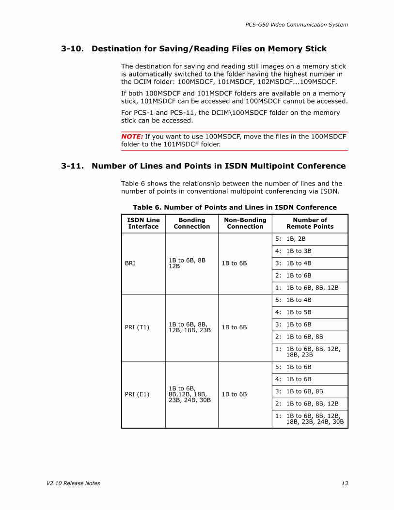
3-10. Destination for Saving/Reading Files on Memory Stick
The destination for saving and reading still images on a memory stick is automatically switched to the folder having the highest number in the DCIM folder: 100MSDCF, 101MSDCF, 102MSDCF...109MSDCF.
If both 100MSDCF and 101MSDCF folders are available on a memory stick, 101MSDCF can be accessed and 100MSDCF cannot be accessed.
For PCS-1 and PCS-11, the DCIM\100MSDCF folder on the memory stick can be accessed.
NOTE: If you want to use 100MSDCF, move the files in the 100MSDCF folder to the 101MSDCF folder.
3-11. Number of Lines and Points in ISDN Multipoint Conference
Table 6 shows the relationship between the number of lines and the number of points in conventional multipoint conferencing via ISDN.
Table 6. Number of Points and Lines in ISDN Conference
ISDN Line Interface
Bonding Connection
Non-Bonding Connection
Number of Remote Points
BRI 1B to 6B, 8B12B 1B to 6B
5: 1B, 2B
4: 1B to 3B
3: 1B to 4B
2: 1B to 6B
1: 1B to 6B, 8B, 12B
PRI (T1) 1B to 6B, 8B, 12B, 18B, 23B 1B to 6B
5: 1B to 4B
4: 1B to 5B
3: 1B to 6B
2: 1B to 6B, 8B
1: 1B to 6B, 8B, 12B, 18B, 23B
PRI (E1)1B to 6B, 8B,12B, 18B, 23B, 24B, 30B
1B to 6B
5: 1B to 6B
4: 1B to 6B
3: 1B to 6B, 8B
2: 1B to 6B, 8B, 12B
1: 1B to 6B, 8B, 12B, 18B, 23B, 24B, 30B
V2.10 Release Notes 13

PCS-G50 Video Communication System
3-12. Service Commands
3-12-1. How to Use Service Commands
1. Access the Setup menu as follows:
Press and hold the MENU button on the remote commander.
2. Select Dial using the button on the remote commander.
3. Access the Service menu as follows:
Press 7 then 2 on the remote commander (without pressing the PUSH ENTER button).
The Service menu appears. (See Figure 7.)
NOTE: To cancel Service mode and return to the Setup menu, select Cancel using the arrow buttons, and press RETURN.
Figure 7
4. Select Command using the arrow buttons, and press PUSH ENTER.
A list of the commands is displayed.
5. Enter the command(s) from the command list using the remote commander.
NOTE:
• To set two or more commands, type a space between the commands, then enter them simultaneously.
• Set only one type of LAN interface. Otherwise, the LAN interface does not operate normally.
• The validated command can always be confirmed from the command list.
• Use only commands from the command list. If any other character string is entered, internal operation may be incorrect.
6. Select Save using the arrow buttons, and press PUSH ENTER.
The Setup menu is displayed.
7. When the LAN interface is set (including when the setting is returned to its initial value), restart the system using the power switch on the communication terminal.
14 V2.10 Release Notes
PCS-G50 Video Communication System
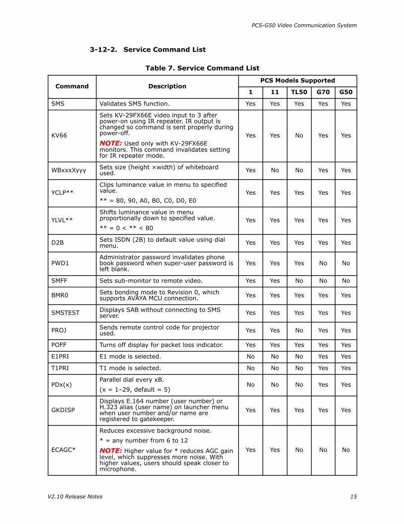
3-12-2. Service Command List
Table 7. Service Command List
Command DescriptionPCS Models Supported
1 11 TL50 G70 G50
SMS Validates SMS function. Yes Yes Yes Yes Yes
KV66
Sets KV-29FX66E video input to 3 after power-on using IR repeater. IR output is changed so command is sent properly during power-off.
NOTE: Used only with KV-29FX66E monitors. This command invalidates setting for IR repeater mode.
Yes Yes No Yes Yes
WBxxxXyyy Sets size (height ×width) of whiteboard used. Yes No No Yes Yes
YCLP**Clips luminance value in menu to specified value.
** = 80, 90, A0, B0, C0, D0, E0Yes Yes Yes Yes Yes
YLVL**Shifts luminance value in menu proportionally down to specified value.
** = 0 < ** < 80Yes Yes Yes Yes Yes
D2B Sets ISDN (2B) to default value using dial menu. Yes Yes Yes Yes Yes
PWD1Administrator password invalidates phone book password when super-user password is left blank.
Yes Yes Yes No No
SMFF Sets sub-monitor to remote video. Yes Yes No No No
BMR0 Sets bonding mode to Revision 0, which supports AVAYA MCU connection. Yes Yes Yes Yes Yes
SMSTEST Displays SAB without connecting to SMS server. Yes Yes Yes Yes Yes
PROJ Sends remote control code for projector used. Yes Yes No Yes Yes
POFF Turns off display for packet loss indicator. Yes Yes Yes Yes Yes
E1PRI E1 mode is selected. No No No Yes Yes
T1PRI T1 mode is selected. No No No Yes Yes
PDx(x)Parallel dial every xB.
(x = 1–29, default = 5) No No No Yes Yes
GKDISPDisplays E.164 number (user number) or H.323 alias (user name) on launcher menu when user number and/or name are registered to gatekeeper.
Yes Yes Yes Yes Yes
ECAGC*
Reduces excessive background noise.
* = any number from 6 to 12
NOTE: Higher value for * reduces AGC gain level, which suppresses more noise. With higher values, users should speak closer to microphone.
Yes Yes No No No
V2.10 Release Notes 15

PCS-G50 Video Communication System
#1236987# Version upgrade of LCD controller software is supported. No No Yes No No
#7896321# Version upgrade feature of LCD controller software. No No Yes No No
HMxChanges Hold sound for SIP phone.
x = 1:Canon; 2:GymnopedieYes No No No No
NATDISP Displays NAT address on Launcher menu. Yes Yes No No No
PKS****Defines video packet size.
**** = 0000 to 9999Yes Yes No Yes Yes
TCBIn Presenter mode of PCSA-CTG70, displays a frame on screen when a moving object is detected.
No No No Yes Yes
NOCIPNDoes not include Calling Party Number (sender number information) in SETUP message during transmission.
Yes Yes Yes No No
SNDCMP Adds Sending Complete to SETUP message during transmission. Yes Yes Yes No No
NOSC Does not add Sending Complete to SETUP message during transmission. Yes Yes Yes No No
Table 7. Service Command List (Continued)
Command DescriptionPCS Models Supported
1 11 TL50 G70 G50
16 V2.10 Release Notes

PCS-G50 Video Communication System
3-13. Keyboard Shortcuts
Table 8. Keyboard Shortcuts
Command Function Comments
00 Communication state display Effective only while communicating.
1~6 Camera preset movement
1~6 (long push) Camera preset registration
71 Main camera
72 Object
73 AUX1
74 AUX2
77 Toggle from 71 to 74
81 Main camera for remote site
82 Object for remote site
83 AUX1 for remote site
84 AUX2 for remote site
88 Toggle from 81 to 84
99 Long push menu Effective only in the menu.
# Address book
* DTMF
PnP Full screen Effective only while not communicating.
Far/Near(long push)
Camera control changes to remote site.
Correspondence schedule from:
PCS-1/11 V3.12PCS-G70/G50 V2.1PCS-TL50 V2.2
V2.10 Release Notes 17

PCS-G50 Video Communication System
4. INTEROPERABILITY
PCS-G50 has been tested with the equipment listed in Tables 9 through 11.
4-1. H.320 Endpoint
Table 9. H.320 Endpoint Interoperability
Equipment Software Version
Aethra VegaSTAR GOLD 6.00.22
Polycom iPower 970 5.1
Polycom iPower 9000 6.2.0.1208
Polycom View Station 512MP 7.5.4
Polycom View Station EX 6.0.3
Polycom View Station FX 6.0.3
Polycom VSX3000 8.0.0
Polycom VSX7000 8.0.0
Sony PCS-1 3.14
Sony PCS-11 3.14
Sony PCS-1600 3.33
Sony PCS-6000 5.02
Sony PCS-G70 2.10
Sony PCS-G50 2.10
Sony PCS-TL50 2.10
Tandberg 500 (Classic) B9.2
Tandberg 550 (Classic) E4.2
Tandberg 550MXP F2.6
Tandberg 770 (Classic) E4.2
Tandberg 770MXP F2.6
Tandberg 800 (Classic) B9.2
Tandberg 880 (Classic) E4.2
Tandberg 880MXP F2.6
Tandberg 990 (Classic) E4.2
Tandberg 990MXP F2.6
Tandberg 1000 (Classic) E4.2
Tandberg 1000MXP F2.6
Tandberg 1500MXP F2.6
Tandberg 2000MXP F2.6
Tandberg 2500 (Classic) E4.2
Tandberg 3000MXP F2.6
Tandberg 6000 (Classic) E4.2
18 V2.10 Release Notes
PCS-G50 Video Communication System
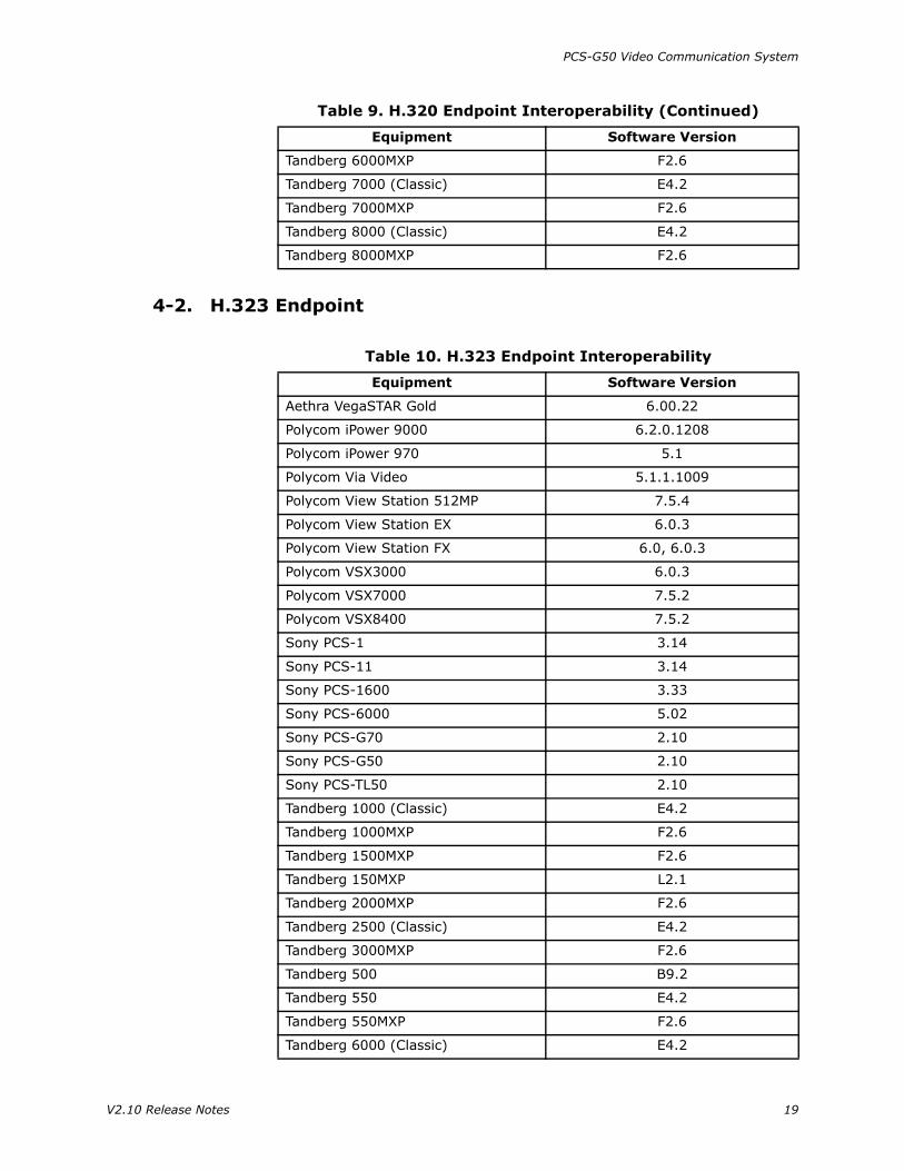
4-2. H.323 Endpoint
Tandberg 6000MXP F2.6
Tandberg 7000 (Classic) E4.2
Tandberg 7000MXP F2.6
Tandberg 8000 (Classic) E4.2
Tandberg 8000MXP F2.6
Table 9. H.320 Endpoint Interoperability (Continued)
Equipment Software Version
Table 10. H.323 Endpoint Interoperability
Equipment Software Version
Aethra VegaSTAR Gold 6.00.22
Polycom iPower 9000 6.2.0.1208
Polycom iPower 970 5.1
Polycom Via Video 5.1.1.1009
Polycom View Station 512MP 7.5.4
Polycom View Station EX 6.0.3
Polycom View Station FX 6.0, 6.0.3
Polycom VSX3000 6.0.3
Polycom VSX7000 7.5.2
Polycom VSX8400 7.5.2
Sony PCS-1 3.14
Sony PCS-11 3.14
Sony PCS-1600 3.33
Sony PCS-6000 5.02
Sony PCS-G70 2.10
Sony PCS-G50 2.10
Sony PCS-TL50 2.10
Tandberg 1000 (Classic) E4.2
Tandberg 1000MXP F2.6
Tandberg 1500MXP F2.6
Tandberg 150MXP L2.1
Tandberg 2000MXP F2.6
Tandberg 2500 (Classic) E4.2
Tandberg 3000MXP F2.6
Tandberg 500 B9.2
Tandberg 550 E4.2
Tandberg 550MXP F2.6
Tandberg 6000 (Classic) E4.2
V2.10 Release Notes 19

PCS-G50 Video Communication System
Tandberg 6000MXP F2.6
Tandberg 7000 (Classic) E4.2
Tandberg 7000MXP F2.6
Tandberg 770 E4.2
Tandberg 770MXP F2.6
Tandberg 800 (Classic) B9.2
Tandberg 8000 (Classic) E4.2
Tandberg 8000MXP F2.6
Tandberg 880 E4.2
Tandberg 880MXP F2.6
Tandberg 990 (Classic) E4.2
Tandberg 990MXP F2.6
Table 10. H.323 Endpoint Interoperability (Continued)
Equipment Software Version
20 V2.10 Release Notes

PCS-G50 Video Communication System
4-3. Miscellaneous Terminals
Table 11. Miscellaneous Interoperability
Terminal Equipment Software Version
H.320 MCUPolycom MGC100 7.0.2
Tandberg MCU D3.1
H.323 MCU
RadVision viaIP400 4.0.31
Polycom MGC100 7.0.2
Tandberg MCU D3.1
Gateway/ Gatekeeper
RadVision viaIP GW 4.0.0.38
RadVision viaIP GK 3.6.0.5
SIP Server NEC SV 7000 —
SIP Endpoint
Aethra VegaSTAR Gold 6.00.22
Sony PCS-1 3.14
Sony PCS-11 3.14
Sony PCS-G70 2.10
Sony PCS-TL50 2.10
Tandberg 8000MXP F2.6
Tandberg 7000MXP F2.6
Tandberg 6000MXP F2.6
Tandberg 3000MXP F2.6
Tandberg 2000MXP F2.6
Tandberg 1500MXP F2.6
Tandberg 1000MXP F2.6
Tandberg 990MXP F2.6
Tandberg 880MXP F2.6
Tandberg 770MXP F2.6
Tandberg 150MXP L2.1
V2.10 Release Notes 21

PCS-G50 Video Communication System
5. VERSION HISTORY
Table 12. Version History
Version Date Released Major Features and Improvements
2.01 07/15/2005• Presentation data transmitted and received
properly.
2.10 09/14/2005
• Support for:
Standard encryptionPRIStreamingUPnP
• TOS set by data type.
• Terminal information displayed on launcher.
• New service command added:
PKS****
• New SIP functions added.
• Web and user interface improved.
• Miscellaneous improvements added.
22 V2.10 Release Notes