video interface for car-solutions.com porsche cayenne with
TRANSCRIPT

model : PIP-RGB-HE-STD-V5 / product code : PIP-RG-0810-861
Video Interface for
Porsche Cayenne with PCM 2.1
User Guide
www.car-solutions.com [email protected]
Car-S
olutio
ns.co
m

-. POP(Picture On Picture) Function (Only available on navigation mode)
-. Auto detection for NTSC & PAL&SECOM signals.
-. Parking Guide Line function added
-. “Sync On Green” supported (Auto detection)
-. Able to change modes via mode switch
-. Able to change modes via using the original buttons(Soldering point will be different depending on car models)
-. OSD Menu added (Controlled by Remote control)
1.1 Features
2www.car-solutions.com [email protected]
Car-S
olutio
ns.co
m

1. Input Spec. (MULTI VIDEO INTERFACE)-. 3 x AV Input (External video source).-. 1 x CVBS (REAR CAMERA) Input (Rear camera source)-. 1 x Analog RGB Input (Car commander original monitor output)-. 1 x Analog RGB Input (Navigation System output)-OPTION
2. Output Spec.-. 2 X CVBS OUTPUT (Video Out for installing Headrest monitor)-. 1 x Audio OUTPUT-. 1 X LCD OUTPUT(LCD Operation)-. 4 X Audio Select Output
3. Power Spec.- Input Power : 8VDC ~ 24VDC - Consumption Power : 5WATT, Max
4. Switch Input mode- NAVI/CVBS1,2 Original MUTE Function : Possible to mute each input by operating Dip S/W- Possible to switch Input mode with remote control or toggle switch.- Rear View Camera mode : When to sense rear gear power, be switched to Rear view
camera mode (Impossible to switch to rear mode with Toggle S/W or the remote control)
1.2 Main Specification
3www.car-solutions.com [email protected]
Car-S
olutio
ns.co
m

4
CVBS OUT HEADRESTMONITOR
MCU
VIDEOCIRCUIT
VIDEO MUX
POWERCIRCUIT
AV 1
CVBS (Rear Camera)
Power Input(+8VDC~+24VDC)
DIP S/W
Remote Control Switch for source toggle & REAR SENSE
Navigation Input(Analog RGB) CAR Installation
OEM LCDDISPLAY
AV 2
CAR SCREEN INPUT(CAR MAIN BOARD)
1.3 System Diagram
AUDIO OUT
AV 3
www.car-solutions.com [email protected]
Car-S
olutio
ns.co
m

1.4 Components
5
POWER cable (10P) * 1ea(HPOWER0005)
RGB cable * 1ea(HNAVIC0002)
MODE cable * 1ea(HARETC0001)
IR cable (3P) * 1ea(HIRCAB0001)
AV cable * 1ea(HAVCAB0002)
REMOTE CONTROL * 1ea(REMOTE0001)
GROUND cable (14P) * 1ea(HGROUN0002)
Sub-board * 1ea(QCPASS0065)
FFC cable (30P) * 1ea(FFCABL0002)
www.car-solutions.com [email protected]
Car-S
olutio
ns.co
m

MODELED
Power/CAN RGB(IN) AV (IN/OUT)
LCD IN/OUTTEST(IR)DIP S/W
1.4 Exterior
DimensionHorizontal length 150mm Vertical length 95mm Height 21mm
6www.car-solutions.com [email protected]
Car-S
olutio
ns.co
m

1.5 Wiring diagram
FILTER & FUSE BOX
* Power cable
AV3-SelAV2-SelAV1-SelNAVI SelCAN(L)-N.CCAN(H)-N.CSAFE-N.CREAR-C
ACCGND
1m
7www.car-solutions.com [email protected]
Car-S
olutio
ns.co
m

※ ON : DOWN, OFF : UP
※DIP S/W Use Example
-. Use Input Mode : AV1, Navigation (RGB), Main-. Rear Camera : When to be installed on CVBS 4
▷ DIP S/W : 1 OFF▷ DIP S/W : 2 OFF ▷ DIP S/W : 3 ON ▷ DIP S/W : 4 ON▷ DIP S/W : 5 OFF▷ DIP S/W : 6 OFF▷ DIP S/W : 7 ON (enable CVBS4)▷ DIP S/W : 8 OFF
2.1 DIP switch
#PIN Function DIP S/W selection
1 RGB INPUT MUTEON : Skipping RGB ModeOFF : RGB Display
2 AV1 MUTEON : Skipping AV1OFF : AV1 Display
3 AV2 MUTEON : Skipping AV2OFF : AV2 Display
4 AV3 MUTEON : Skipping AV3OFF : AV3Display
5 OEM MUTEON : Skipping OEMOFF : OEM Display
6 N.C
7 REAR MODEON : External Rear CameraOFF : OEM Rear Camera
8 N.C
8www.car-solutions.com [email protected]
Car-S
olutio
ns.co
m

*FACTORY MODE (Interface setting) : Operated with pressing ▲ -> ▼ -> ▲ ->MENU buttons of the remote in sequence.
Dimension : 85 * 40 * 8 (mm)
Key Function
POWER & PIP Not for use
MENU OSD implementation
OK Making a selection
▲ Move upward, control of POP position
▼ Move downward
◀ Move leftward
▶ Move rightward
(Example : PIP implementation)
2.2 Remote controller
9www.car-solutions.com [email protected]
Car-S
olutio
ns.co
m

IMAGE- BRIGHTNESS- CONTRAST- SATURATION - HUE- SHARPNESS- USER IMAGE : To choose a option among 4 prepared color shade.
OSD- LANGUAGE : Choosing OSD language
while using Touch OSD (English, Chinese only)
- TRANS : Transparency control of the OSD background- H_POSITION : Horizontal movement of the OSD window- V_POSITION : Vertical movement of the OSD window
UTIL - FACTORY RESET : To reset all the values about navigation, DVD screento factory default. (NOT available for reset of the position value of images, only for functions inside OSD menu)
Analog RGB
Video
Analog RGB
Video
Analog RGB
Video
2.3 OSD (On Screen Display)
10www.car-solutions.com [email protected]
Car-S
olutio
ns.co
m

PARK
- PARK ENABLE
- H-POSITION
- V-POSITION
· Factory Mode- Operated with pressing ▲ -> ▼ -> ▲ ->MENU buttons of the remote in sequence.
2.3 OSD (On Screen Display)
UTIL
- BUTTON : Car Model Setting for using Navi button
(Refer to the next page for details)
- FACTORY RESET : Initializing
11www.car-solutions.com [email protected]
Car-S
olutio
ns.co
m

※ This setting needed with wire soldering, if want to use Navi button for switching AV sources. (Refer to the next page for further details.)
2.3 OSD (On Screen Display)
12www.car-solutions.com [email protected]
Car-S
olutio
ns.co
m

①
②
* Factory Default : DISPLAY - DISABLE
① When the car gear is in reverse, Enter to the Factory mode by ▲ → ▼ → ▲→MENU button of remote control.
Then, the left image will be displayed on the screen.
② Set “PARK ENABLE” to “ON” on the park mode, then the line will be displayed as shown left.
* If you would like to remove this line, just select “Off” on the above process.
2.4 Parking guide line
13www.car-solutions.com [email protected]
Car-S
olutio
ns.co
m
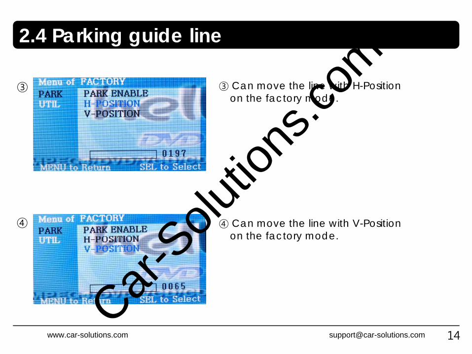
③
④
③ Can move the line with H-Positionon the factory mode.
④ Can move the line with V-Positionon the factory mode.
2.4 Parking guide line
14www.car-solutions.com [email protected]
Car-S
olutio
ns.co
m

Ignition key should be taken off before starting installation, interface power connection must be the last step in installation.
Power cable should be separated when connecting interface.
Should be no any electronic devices or magnetic pole around installation place.
All steps of installation should be done by well-trained specialist.
Dismantling without manufacturer’s permission can not be guaranteed, (No permission to break attached label on the board.)
Kindly check all parts are in the box, when receiving the product, if anything missing, inform to the supplier or manufacturer.
According to our sales policy, any problems caused by user’s mistake, careless can not be guaranteed.
3.1 Cautions on installation
15www.car-solutions.com [email protected]
Car-S
olutio
ns.co
m

LED
POWER/CAN RGB(IN)
PIP RGB Hi-End
TEST
A/V(IN/OUT)
DIP S/W MODE LCD IN/OUT
Control Box
•If want to use Navi button, Soldergray wire of offered LCD cable to appointed point inside Head Unit.- Applicable models : Cayenne 05~08 year, W164US, W211, Pheaton)
MONITOR
OfferedFFC
OriginalFFC
3.2 Installation diagram
16
R D
ATA
(red)
G D
ATA
(green)
B DATA
(blue)
N.C
SYNC (w
hite)GN
D (b
lack)N
.C
VID
EO
AUDIO R
AUDIO L
REAR C
AV
1
AV
2
AV
3
AV
/OU
T
YELLOW
YELLOW
RED
WH
ITE
AV3-SEL
AV2-SEL
AV1-SEL
NAVI SEL
CAN(L)
CAN(H)
SAFE
REAE-C
GND
ACC
※ Please make sure that the installation should be carefully conducted to avoid from the damage of a monitor by ESD(Electrostatic discharge) and misalignment while connecting the module of a monitor with cables.
www.car-solutions.com [email protected]
Car-S
olutio
ns.co
m
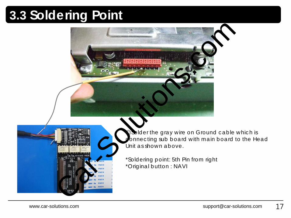
◎Solder the gray wire on Ground cable which is connecting sub board with main board to the Head Unit as shown above.
*Soldering point: 5th Pin from right*Original button : NAVI
3.3 Soldering Point
17www.car-solutions.com [email protected]
Car-S
olutio
ns.co
m
Q. I can not switch A/V sources.A. Check IR or Ground cable connection. Check LED lamps in the interface, if it is not on, check power cable.
Q. All I got on the screen is black.A. Check second LED lamp of the interface is on, if not, check A/V sources connected are working well.
(Second lamp indicates AV sources connected works well.) Check interface connection has been done well.
Q. Displayed image color is not proper. (too dim or not suitable color) A. Try to select “INITIAL” in OSD menu, if it does not work, inform the manufacturer.)
Q. Rear camera image does NOT appear.A. Set DIP switch #7 in “ON”
Q. Unwanted A/V mode is displayed. (A/V source switching order : OEM->RGB->AV1->AV2->AV3) A. Check DIP Switch Setting.
Q. OEM image is not displayed.A. Check interface’s LCD In/Out cable connection. If the status keeps on, inform the manufacturer.
Q. Screen only displays white like left picture.A. Check LCD out cable is connected well, if this status keeps, inform the manufacturer.
4. Troubleshooting
18www.car-solutions.com [email protected]
Car-S
olutio
ns.co
m