view zone offroad c37n/c38n instructions - 4x4 media4x4media.info/instructions/zon/c2311.pdf ·...
TRANSCRIPT

»Zone Offroad Products • 491 W. Garfield Ave., Coldwater, MI 49036 • 888.998.ZONE • www.zoneoffroad.com
Read and understand all instructions and warnings prior to installation of product and operation of vehicle.Zone Offroad Products recommends this system be installed by a professional technician. In addition to these instructions, profes-sional knowledge of disassembly/ reassembly procedures and post installation checks must be known. Minimum tool requirements include the following: Assorted metric and standard wrenches, hammer, hydraulic floor jack and a set of jack stands. See the "Special Tools Required" section for additional tools needed to complete this installation properly and safely.
»Product Safety Warning
Certain Zone Suspension Products are intended to improve off-road performance. Modifying your vehicle for off-road use may result in the vehicle handling differently than a factory equipped vehicle. Extreme care must be used to prevent loss of control or vehicle rollover. Failure to drive your modified vehicle safely may result in serious injury or death. Zone Offroad Products does not recom-mend the combined use of suspension lifts, body lifts, or other lifting devices.
You should never operate your modified vehicle under the influence of alcohol or drugs. Always drive your modified vehicle at re-duced speeds to ensure your ability to control your vehicle under all driving conditions. Always wear your seat belt.
»technical SuPPort
Live Chat provides instant communication with Zone tech support. Anyone can access live chat through a link on www.zoneoffroad.com .
www.zoneoffroad.com may have additional information about this product including the lat-est instructions, videos, photos, etc.
Send an e-mail to [email protected] detailing your issue for a quick response.
888.998.ZONE Call to speak directly with Zone tech support.
»Pre-inStallation noteS
1. Special literature required: OE Service Manual for model/year of vehicle. Refer to manual for proper disassembly/reassembly procedures of OE and related components.
2. Adhere to recommendations when replacement fasteners, retainers and keepers are called out in the OE manual.
3. Larger rim and tire combinations may increase leverage on suspension, steering, and related components. When selecting combinations larger than OE, consider the ad-ditional stress you could be inducing on the OE and related components.
4. Post suspension system vehicles may experience drive line vibrations. Angles may require tuning, slider on shaft may require replacement, shafts may need to be lengthened or trued, and U-joints may need to be replaced.
5. Secure and properly block vehicle prior to installation of Zone Offroad Products. Always wear safety glasses when using power tools.
6. If installation is to be performed without a hoist, Zone Offroad Products recommends rear alterations first.
7. Due to payload options and initial ride height variances, the amount of lift is a base figure. Final ride height dimensions may vary in accordance to original vehicle attitude. Always measure the attitude prior to beginning installation.
rev071415
C2311 Installation Instructions2011-15 Chevy/GM 2500/3500 HD 4wd3" Suspension System
Difficulty Leveleasy 1 2 3 4 5 difficult
Estimated installation: 3-4 hours
Special Tools RequiredTorsion Bar Tool - GM #CH48809
Tire/Wheel FitmentTire: 34x11.50 (285/75/17)
Wheel:
- 17/18/20 x 9 w/ 5" to 6" BS
- Over 20", use 20" specs

C1244, C1245 Installation - pg. 2
*Important* Verify you have all of the kit components before beginning installation.
C2311 Kit ContentsQty Part1 DRV Arm Assembly1 HD Ball Joint2 Rubber Bushing1 Ball Joint Cap1 Grease Zerk1 O-ring 1 PASS Arm Assembly1 HD Ball Joint2 Rubber Bushing1 Ball Joint Cap1 Grease Zerk1 O-ring2 7/8" Differential Spacer Sleeve - Frt2 1/2" Differential Spacer Sleeve - Rear2 11+ Hd Torsion Keys1 Bolt pack 679 - Diff Drop 2 9/16"-12 x 5" bolt
2 9/16"-12 x 5-1/2" bolt
8 9/16" SAE thru hardened washer
4 9/16"-12 prevailing torque nut
C1207 Rear 2" Block Kit Contents2 2" Flat Block - 18mm pin4 3/4" x 3-1/4 x 13-1/2 Square U-bolt8 3/4" Serrated Edge Flanged Nut

C1244, C1245 Installation - pg. 3
PRE-INSTALLATION NOTES1. The torsion bars are under extreme pressure and require the use of a Kent Moore
#CH48809 torsion bar tool or equivalent for proper unloading/loading. Follow tool manufacturer instructions.
INSTALLATION INSTRUCTIONS1. Park vehicle on clean, flat, and level surface. Block the rear wheels for safety.
2. Measure the ride height of the vehicle and record - see side box.
3. Raise the front of the vehicle with a hydraulic jack. Support the frame rails with jackstands. Figure 1
Torsion Key
Torsion Bar
Adjuster Bolt
Figure 1
4. Measure the length of the torsion bar adjuster bolts (top of the adjuster bolt head to adjuster) and record - see side box.
5. Remove the adjuster bolts, keep driver's and pass side bolts separate.
6. Use the torsion bar removal tool to remove the threaded adjuster assembly. Release the pressure from torsion bar with the unloading tool. Caution: There is an extreme amount of energy stored in the torsion bars. Use extreme care with the proper tools to avoid serious injury or death.
7. Slide the torsion bars forward to allow the factory keys to be removed. On older vehicles, it may be necessary to use an air hammer to get the bars to break free.
8. Apply a small amount of grease to the hex on each end of the torsion bar. Install the new torsion keys. When installed the keys should be nearly horizontal and pointing toward each other. Because of slight differences in hex shape, the fac-tory and Zone keys will appear to have very similar indexing. Do not install the torsion bar bridge or bolt at this time.
Important—measure before starting!Measure from the center of the wheel up to the bottom edge of the wheel opening
LF__________ RF__________
LR__________ RR__________
Important - Measure from the exposed length of the torsion bar adjusters before starting:
Drv_________ Pass__________
Caution: There is an extreme amount of energy stored in the tor-sion bars. Use extreme care with the proper tools to avoid serious injury or death.

C1244, C1245 Installation - pg. 4
Shock Extension/New Shock Installation9. Remove the upper shock nuts and lower shock bolt. Remove shocks from ve-
hicle. Installing longer aftermarket replacement shocks with the spacer on top of the bar pin. Attach shock to the upper mount with new 12mm nuts and washer tighten upper mount to 55 ft-lbs, lower mount to 95 ft-lbs. Figure 2
Figure 2
Upper Control Arm Installation:10. Remove the upper ball joint nut, reinstall a couple of turns. Hit the side of the
knuckle to dislodge the upper ball joint from the steering knuckle. Remove the factory upper control arm from the vehicle. Figure 3a, 3b
Figure 3a

C1244, C1245 Installation - pg. 5
Figure 3b
11. Install new upper control arm assembly with factory cam bolts. Arms are side specific. Snug, but do not tighten at this time. Attach the upper ball joint to the steering knuckle with provided nut, washer, and cotter pin. Tighten the upper ball joint nut to 55 ft-lbs before installing cotter pin. Figure 4
Figure 4
Note:
02567 part # is stamped in the driver's side arm
02765 is stamped in the passenger's side arm.
Ball joint will be offset towards the rear of the vehicle
Grease the Ball Joint!!!

C1244, C1245 Installation - pg. 6
Differential Drop Installation:12. The differential area on the driver's side will need to have a small chamfer
ground into it for clearance when the differential is lowered. Locate the area shown and use a rotary die grinder tool to put a small 1/4" wide chamfer onto the differential, not much material is required to be removed. Figure 5
Figure 5
13. Work on one side of the vehicle at a time. Remove the hardware that attaches the differential mounts to the frame. Figure 6a
Figure 6a

C1244, C1245 Installation - pg. 7
14. Lower the differential and install the spacers between the frame mounting points and the factory brackets. Use the short spacer at the rear mount with 9/16" x 5" hardware. Use the tall spacer at the front mount with 9/16" x 5-1/2" hardware. Figure 6b
Figure 6b
Torsion Key Installation15. Install the torsion bar adjuster assembly with torsion bar tool.
16. Set the overall length of the exposed thread and bolt head to the original mea-surement. The minimum recommended length is 3/4". This may need to be adjusted if heavy accessories are added to the front of the vehicle.
17. Lower the front end to the ground, roll the vehicle forward and back to settle the suspension.
18. Check the final ride height measurement. This should not be more than 27-3/4". If it is greater than this, the adjusters need to be lowered.
19. Center the upper control arm cams. Tighten the cam bolts to 140 ft-lbs.
20. A front end alignment must now be performed.
21. Check hardware after 500 miles. Adjust headlights.
C1244, C1245 Installation - pg. 8
Rear Installation1. Block the front wheels for safety. Raise the rear of the vehicle and support with
jack stands under the frame rails, just ahead of the front leaf spring hangers.
2. Remove the wheels.
3. Raise rear of vehicle and support frame with jackstands.
4. Support the rear axle with a hydraulic jack.
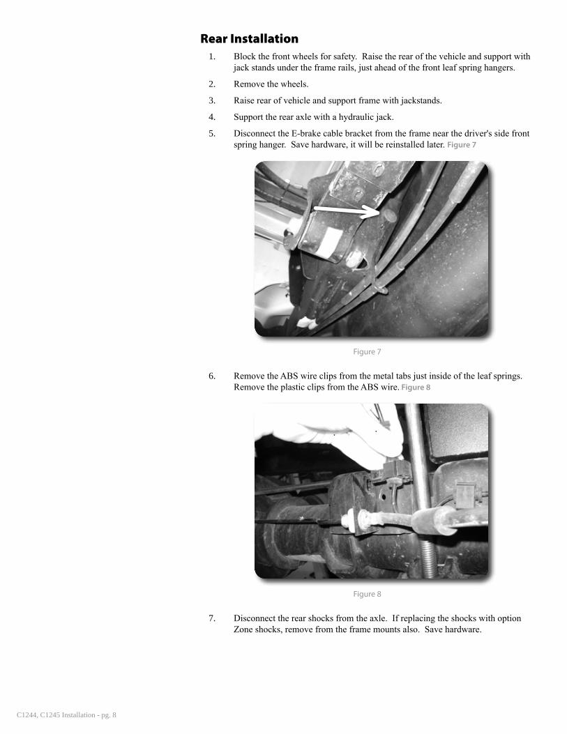
5. Disconnect the E-brake cable bracket from the frame near the driver's side front spring hanger. Save hardware, it will be reinstalled later. Figure 7
Figure 7
6. Remove the ABS wire clips from the metal tabs just inside of the leaf springs. Remove the plastic clips from the ABS wire. Figure 8
Figure 8
7. Disconnect the rear shocks from the axle. If replacing the shocks with option Zone shocks, remove from the frame mounts also. Save hardware.

C1244, C1245 Installation - pg. 9
8. Locate the brake line bracket at the top of the differential. Using an adjustable wrench carefully bend the bracket upward so that ends of the rubber brake lines point toward the frame. Figure 9, 10 Carefully adjust the brake hardlines that run along the axle.
Figure 9
Figure 10
9. With the axle well supported, remove the passenger’s side u-bolts and lower u-bolt plate. Loosen, but do not remove the u-bolt hardware on the driver’s side. This will allow the axle to move more easily and aid in installation.

C1244, C1245 Installation - pg. 10
2" Lift Block Installation10. Install the new blocks between the axle and the leaf spring. Align the pins/holes
and raise the axle to seat the assembly. Install the new provided u-bolts with the factory u-bolt plate. Figure 12 Fasten with the provided locking flange nuts. Snug hardware. Final torque will be down with the vehicle on the ground.
Figure 12
11. Repeat block installation of the driver's side.
12. With both sides complete, secure the ABS wire to the inside u-bolt with the provided zip ties. Figure 13
Figure 13
13. Check all cables for adequate slack at full droop, make adjustments if necessary.
14. INSTALLING NEW OPTIONAL ZONE SHOCKS ONLY: The passenger's side bump stop bracket on the axle must be trimmed slightly to add clearance for the new larger rear shocks. Grind the inside front corner to gain approximately 1/4" of clearance. Figure 14 Paint bare metal to prevent rust.

C1244, C1245 Installation - pg. 11
Figure 14
15. Reattach shocks to the axle with factory hardware. If installing new optional Zone shocks, install them with the original frame and axle hardware. Torque hardware to 85 ft-lbs.
16. Remove the driver's side parking brake cable from the driver's side bracket that was removed from the frame. Move the passenger's side cable into the lower section of the bracket. Reattach the bracket to the frame and tighten hardware securely. Figure 15
Figure 15
17. Remove clips on wheels Figure 16. Reinstall wheels and lower vehicle to the ground. Torque u-bolts to 150 ft-lbs. Torque lug nuts to 140 ft-lbs.

C1244, C1245 Installation - pg. 12
Figure 16
Post-Installation1. Check all hardware for proper torque.
2. Reconnect the positive and negative battery cables.
Front Tire Clearance1. Depending on the tire/wheel combination used, the front lower corner of the
front bumper may need to be trimmed. This is very common with most GM/Chevy trucks.
2. For additional clearance, the front lower edge of the inner fenders can be relocated forward 1". Located and disconnect the two bolts holding the lower edge of the fender to the bottom of the bumper. Redrill the 2 mounting holes 1" forward and reconnect. Figure C
Post-Installation Warnings1. Check all fasteners for proper torque. Check to ensure for adequate clearance between all rotating, mobile, fixed, and heated members. Verify clearance between exhaust and brake lines, fuel lines, fuel tank, floor boards and wiring harness. Check steering gear for clearance. Test and inspect brake system.
2. Perform steering sweep to ensure front brake hoses have adequate slack and do not contact any rotating, mobile or heated members. Inspect rear brake hoses at full extension for adequate slack. Failure to perform hose check/ re-placement may result in component failure.
3. Perform head light check and adjustment.
4. Re-torque all fasteners after 500 miles. Always inspect fasteners and components during routine servic-ing.

C1244, C1245 Installation - pg. 13
Figure C
Final Check1. The vehicle will need a complete front end alignment.
2. Check all hardware after 500 miles.
3. Adjust headlights.