vip-2e volume initiated programmable controller ... · volume initiated programmable controller...
TRANSCRIPT

Form No. 999428 – Rev. 3 Effective 7/12/12
Volume Initiated Programmable Controller Programming Guide
VIP-3E
VIP-2E

Form No. 999428 – Rev. 3 Effective 7/12/12
Form No. 999428 – Rev. 3 Effective 7/12/12
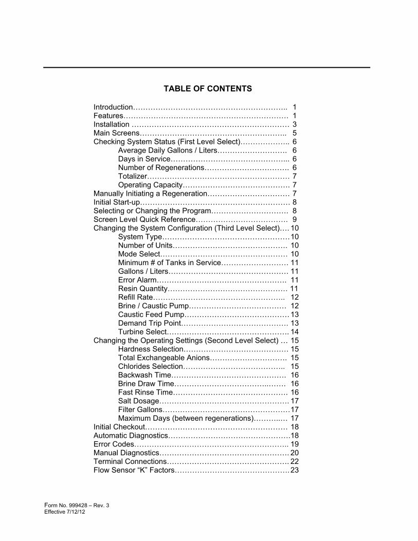
TABLE OF CONTENTS Introduction…………………………………………………….. 1 Features………………………………………………………… 1 Installation ……………………………………………………… 3 Main Screens………………………………………………….. 5 Checking System Status (First Level Select)……………….. 6 Average Daily Gallons / Liters………………………. 6 Days in Service………………………………………... 6 Number of Regenerations……………………………. 6 Totalizer………………………………………………… 7 Operating Capacity……………………………………. 7 Manually Initiating a Regeneration…………………………… 7 Initial Start-up…………………………………………………… 8 Selecting or Changing the Program…………………………. 8 Screen Level Quick Reference………………………………. 9 Changing the System Configuration (Third Level Select)…. 10 System Type…………………………………………… 10 Number of Units………………………………………. 10 Mode Select…………………………………………… 10 Minimum # of Tanks in Service……………………… 11 Gallons / Liters………………………………………… 11 Error Alarm……………………………………………. 11 Resin Quantity………………………………………… 11 Refill Rate…………………………………………….. 12 Brine / Caustic Pump………………………………… 12 Caustic Feed Pump…………………………………… 13 Demand Trip Point……………………………………. 13 Turbine Select…………………………………………. 14 Changing the Operating Settings (Second Level Select) … 15 Hardness Selection…………………………………… 15 Total Exchangeable Anions…………………………. 15 Chlorides Selection………………………………….. 15 Backwash Time………………………………………. 16 Brine Draw Time………………………………..……. 16 Fast Rinse Time………………………………………. 16 Salt Dosage……………………………………………. 17 Filter Gallons…………………………………………… 17 Maximum Days (between regenerations)………..… 17 Initial Checkout………………………………………………… 18 Automatic Diagnostics…………………………………………. 18 Error Codes…………………………………………………….. 19 Manual Diagnostics……………………………………………. 20 Terminal Connections…………………………………………. 22 Flow Sensor “K” Factors………………………………………. 23

Form No. 999428 – Rev. 3 Effective 7/12/12

Form No. 999428 Rev. 3 Effective 7/12/12
1
OVERVIEW
Introduction
The VIP-2/3E Control is a computer based, demand initiated controller for commercial and industrial Water Softener, Dealkalizer, and Filter systems. The controller operates by sensing water flow to optimally control system operation. Softeners, Dealkalizers, and Filters can be operated as two, three, or four tank alternating, parallel, or variable flow softener systems. Additionally, the computer provides powerful features, which allow precise monitoring of system performance and detailed assistance in diagnosing problems.
The VIP-2/3E works with a full line of 1” (A), 11/2” (B), 2” (C), and 3” (E) commercial and industrial softener, dealkalizer, and filter valves. The control accepts flow signals from a number of Hall effect type flow sensors. When operated in conjunction with ¾” (Z), 1” (A), 1-1/2” (B), or 2” (C) VIP flow sensors, the computer will automatically make low flow rate corrections to improve accuracy. For larger system requirements, the controller operates with 3”, 4” or larger insertion type paddlewheel flow meters.
Features
4 Button Key Pad 1 - SELECT 2 - UP ARROW 3 - DOWN ARROW 4 - REGEN
Alphanumeric Display
Nema 4X Enclosure with hinged cover
Twist Lock Connectors are located on bottom of control. The connectors are for systems 1 thru 4 – from left to right.
Bottom View of Control
#1 Flow Meter Connector
#1 Valve Connector
Form No. 999428 Rev. 3 Effective 7/12/12
2
OVERVIEW
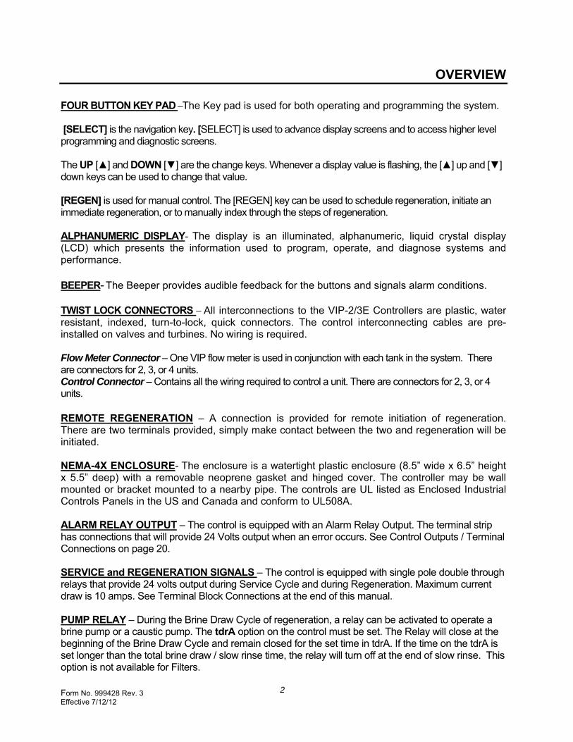
FOUR BUTTON KEY PAD –The Key pad is used for both operating and programming the system.
[SELECT] is the navigation key. [SELECT] is used to advance display screens and to access higher level programming and diagnostic screens.
The UP [▲] and DOWN [▼] are the change keys. Whenever a display value is flashing, the [▲] up and [▼] down keys can be used to change that value.
[REGEN] is used for manual control. The [REGEN] key can be used to schedule regeneration, initiate an immediate regeneration, or to manually index through the steps of regeneration. ALPHANUMERIC DISPLAY- The display is an illuminated, alphanumeric, liquid crystal display (LCD) which presents the information used to program, operate, and diagnose systems and performance. BEEPER- The Beeper provides audible feedback for the buttons and signals alarm conditions. TWIST LOCK CONNECTORS – All interconnections to the VIP-2/3E Controllers are plastic, water resistant, indexed, turn-to-lock, quick connectors. The control interconnecting cables are pre-installed on valves and turbines. No wiring is required.
Flow Meter Connector – One VIP flow meter is used in conjunction with each tank in the system. There are connectors for 2, 3, or 4 units. Control Connector – Contains all the wiring required to control a unit. There are connectors for 2, 3, or 4 units. REMOTE REGENERATION – A connection is provided for remote initiation of regeneration. There are two terminals provided, simply make contact between the two and regeneration will be initiated. NEMA-4X ENCLOSURE- The enclosure is a watertight plastic enclosure (8.5” wide x 6.5” height x 5.5” deep) with a removable neoprene gasket and hinged cover. The controller may be wall mounted or bracket mounted to a nearby pipe. The controls are UL listed as Enclosed Industrial Controls Panels in the US and Canada and conform to UL508A. ALARM RELAY OUTPUT – The control is equipped with an Alarm Relay Output. The terminal strip has connections that will provide 24 Volts output when an error occurs. See Control Outputs / Terminal Connections on page 20. SERVICE and REGENERATION SIGNALS – The control is equipped with single pole double through relays that provide 24 volts output during Service Cycle and during Regeneration. Maximum current draw is 10 amps. See Terminal Block Connections at the end of this manual.
PUMP RELAY – During the Brine Draw Cycle of regeneration, a relay can be activated to operate a brine pump or a caustic pump. The tdrA option on the control must be set. The Relay will close at the beginning of the Brine Draw Cycle and remain closed for the set time in tdrA. If the time on the tdrA is set longer than the total brine draw / slow rinse time, the relay will turn off at the end of slow rinse. This option is not available for Filters.

Form No. 999428 Rev. 3 Effective 7/12/12
3
INSTALLATION
CONTROL INSTALLATION
Wall Mounting
Pipe Mounting
Plastic Wall Mounting brackets are supplied with the VIP Control. The brackets should be bolted onto the back of the control with the screws provided. The mounting tabs are shown at the left and right of the control at the right.
Mounting Brackets
Attach the Wall Mount brackets (rotated 180O) on the back of the control. Mount the section of Unistrut in the position indicated in the photographs below (screws and washers are provided). The photo on the left can be used as a guide if the support pipe runs vertically. If the support pipe runs horizontally then the photo on the right can be used as a guide. The Unistrut pipe clamp is then mounted to the Unistrut and positioned as desired and held in place with the nut and bolt provided.
Unistrut Pipe Clamp
Photo showing position of Unistrut if support piping is
running vertical
Photo showing position of Unistrut if support piping is
running horizontal
Unistrut
Wall Mount Brackets
Unistrut
Unistrut Pipe Clamp
Form No. 999428 Rev. 3 Effective 7/12/12
4
INSTALLATION
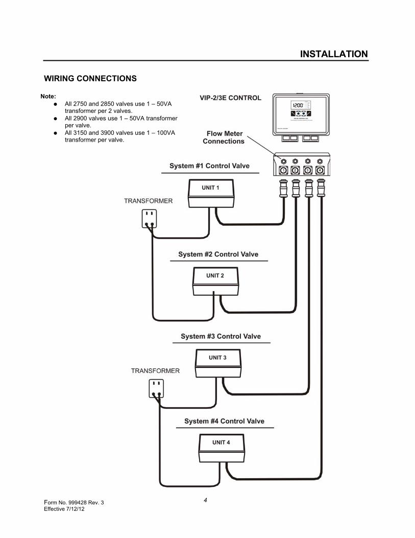
WIRING CONNECTIONS
Note: All 2750 and 2850 valves use 1 – 50VA
transformer per 2 valves. All 2900 valves use 1 – 50VA transformer
per valve. All 3150 and 3900 valves use 1 – 100VA
transformer per valve.

Form No. 999428 Rev. 3 Effective 7/12/12
5
OPERATION NOTE: If This Is A First Time Start-Up, Refer to and Complete The Programming Steps In Programming The VIP-2/3E Control.
The Main Screens The Main Screens – The unit/charge bar screen and the flow rate screen are the default display screens for the controller. The Main Screens are the starting points from which system, status, settings, configuration, and diagnostics can be reached. Once the control has been initially programmed or after being left idle for four (4) minutes, the display will always revert back to the Main Screen from any other screen.
Unit / Charge Bar Screen
In normal operation, the system will continuously step through the units in a system and display Unit/Charge Bar Screen and then the Flow Rate Screen.
The Unit Number identifies an individual unit in the system and it’s corresponding Charge Bars. It also indicates to which unit the next Flow Rate screen is referring. The Flow Rate Screen indicates the amount of flow passing through the system for a particular tank. The Charge Bar indicates the percentage of unused operating capacity remaining. The figure indicates that 100% of the operating capacity remains. As capacity is depleted, the charge bar segments are reduced. During reconditioning, the charge bar segments are added as the regeneration cycle takes place.
Recharge
When the small RCHG segment is visible in the display, a regeneration has been scheduled for that unit. The regeneration will occur in a sequence determined by the computer. When the word Recharge flashes in the display, regeneration is currently underway for that unit. The Recharge segment will continue to flash until the regeneration is complete.
Form No. 999428 Rev. 3 Effective 7/12/12
6
OPERATION
Checking System Status (First Level Select)
The [SELECT] key is the navigational key. Pressing and releasing this key repeatedly can access operation and status information screens,
NOTE: BEEPER – A beeper sounds while pressing buttons for setup. One beep signals a change in the display. Three repeated beeps indicates the button pressed is invalid, telling you to try another button.
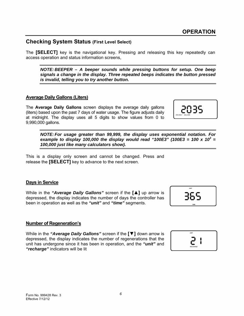
Average Daily Gallons (Liters)
The Average Daily Gallons screen displays the average daily gallons (liters) based upon the past 7 days of water usage. The figure adjusts daily at midnight. The display uses all 5 digits to show values from 0 to 9,990,000 gallons.
NOTE: For usage greater than 99,999, the display uses exponential notation. For example to display 100,000 the display would read “100E3” (100E3 = 100 x 103 = 100,000 just like many calculators show).
This is a display only screen and cannot be changed. Press and release the [SELECT] key to advance to the next screen.
Days in Service
While in the “Average Daily Gallons” screen if the [▲] up arrow is depressed, the display indicates the number of days the controller has been in operation as well as the “unit” and “time” segments.
Number of Regeneration’s
While in the “Average Daily Gallons” screen if the [▼] down arrow is depressed, the display indicates the number of regenerations that the unit has undergone since it has been in operation, and the “unit” and “recharge” indicators will be lit

Form No. 999428 Rev. 3 Effective 7/12/12
7
OPERATION
Totalizer
The Totalizer screen indicates the total amount of treated water that has passed by the turbines. Accumulated flow is shown in gallons (liters) up to 9,990,000 gallons. For display values greater than five (5) digits, a scientific notation is used. When 999E4 (9,990,000) is reached the counter will roll over back to 0 and resume counting.
Press and release the [▼] down arrow key to manually reset this value to zero. Press and release the [SELECT] key to advance to the next screen.
Operating Capacity
The Operating Capacity screen displays the “per tank” operating capacity (in grains) of the system. Capacity is a function of the Resin (Ft3) and the salt dosage (lbs./ Ft3) used to regenerate. If the capacity is over 99,999 grains, exponential notation is used.
This is a display only screen and cannot be changed. Press and release to advance back to the Main screen.
Manually Initiating a Regeneration
Press and hold [REGEN] button for 3 seconds to start a regeneration. RECHARGE will flash in the display for the unit currently regenerating. If the control is programmed for Softeners or Dealkalizers, only one unit will regenerate and return to stand-by or service as programmed. If the control is programmed for Filters, all the filters will regenerate in sequence. The RECHARGE will flash on the filter regenerating and the RCHG will be lit on the other units indicating regeneration is scheduled for those units. To remove the additional scheduled regenerations simply push and hold the [REGEN] button for 3 seconds a second time.
Form No. 999428 Rev. 3 Effective 7/12/12
8
PROGRAMMING VIP-2/3E CONTROL
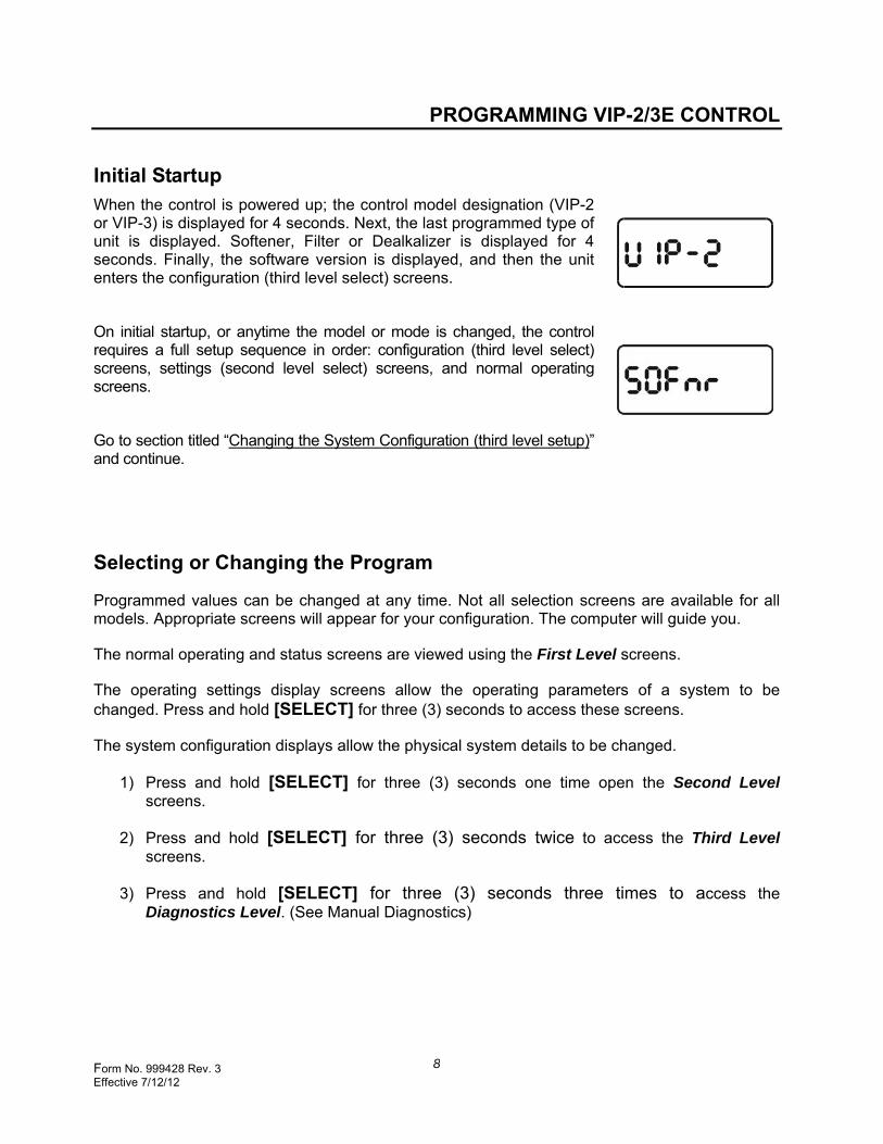
Initial Startup When the control is powered up; the control model designation (VIP-2 or VIP-3) is displayed for 4 seconds. Next, the last programmed type of unit is displayed. Softener, Filter or Dealkalizer is displayed for 4 seconds. Finally, the software version is displayed, and then the unit enters the configuration (third level select) screens.
On initial startup, or anytime the model or mode is changed, the control requires a full setup sequence in order: configuration (third level select) screens, settings (second level select) screens, and normal operating screens.
Go to section titled “Changing the System Configuration (third level setup)” and continue.
Selecting or Changing the Program
Programmed values can be changed at any time. Not all selection screens are available for all models. Appropriate screens will appear for your configuration. The computer will guide you.
The normal operating and status screens are viewed using the First Level screens.
The operating settings display screens allow the operating parameters of a system to be changed. Press and hold [SELECT] for three (3) seconds to access these screens.
The system configuration displays allow the physical system details to be changed.
1) Press and hold [SELECT] for three (3) seconds one time open the Second Level screens.
2) Press and hold [SELECT] for three (3) seconds twice to access the Third Level screens.
3) Press and hold [SELECT] for three (3) seconds three times to access the Diagnostics Level. (See Manual Diagnostics)

Form No. 999428 Rev. 3 Effective 7/12/12
9
PROGRAMMING VIP-2/3E CONTROL
Screen Level Quick Reference
The guide that follows can be used as a quick reference for the different levels of programming.
FIRST LEVEL DATA –
Average Daily Gallons
Days in Service
Number of Regenerations Completed
Total Gallons
Operating Capacity
SECOND LEVEL DATA –
Hardness for Softener or TEA for Dealkalizer
Chloride content – Dealkalizer only
Backwash Time
Brine Draw / Slow Rinse Time
Rinse Time
Salt Dosage
Minimum Days between Regenerations THIRD LEVEL DATA –
System Type Select (Softener, Filter or Dealkalizer)
Number of Units
Mode Select - Alternating or Parallel (or Variable – VIP-3E)
Minimum Number of Units in Service
Gallons or Liters Select
Beep (on / off)
Resin Quantity
Refill Rate
Time Delay Relay Output (tdrA)
Caustic Feed – Dealkalizer only (yes – no)
Trip Point Set (VIP-3)
Turbine Size or Adj.
Note: Pushing and holding the select button for 3 seconds – twice in a row will open the Third Level Data. When programming from this point – the control will automatically go through the Second Level Data also.

Form No. 999428 Rev. 3 Effective 7/12/12
10
PROGRAMMING VIP-2/3E CONTROL
Changing The System Configuration (Third Level Select)
The third level select screens are accessed in two ways:
Initial Startup The first time the control is powered up, the system enters Third Level Select screens. Manual Entry Press and hold the [SELECT] button for 3 seconds then release. Press and hold [SELECT] for 3 seconds a second time; the control will enter the third level setup screens.
System Type Select
The System Type selection screen is used to designate what type of system the control will operate. The three options are Softener, Filter, or Dealkalizer. When Softener or Dealkalizer is selected, the control will operate a variety of valves or valve nest stagers with 5-cycle reconditioning steps – service, backwash, brine rinse, fast rinse, and separate time fill. When Filter is selected, the control will operate a variety of valves or valves nest stagers with 3-cycle reconditioning steps – service, backwash, and fast rinse.
The [▲] up and [▼] down arrow keys are used to change the selection. Pressing the [SELECT] key confirms the choice and advances the control to the next screen.
NOTE: BEEPER – A beeper sounds while pressing buttons for setup. One beep signals a change in the display. Repeat beeps indicate the button pressed is invalid, telling you to try another button.
Number of Units Select
The number of units selection screen is used to tell the system how many units will be used in the system. The minimum is 2 units and the maximum is 4 units.
Mode Select
Different softener and filter valves can be operated in a variety of different modes. Three (3) choices are possible with the VIP II/III Control.
ALT A system that operates in an alternating mode. PAR A system that operates in a parallel mode. VAR A system that moves units into and out of service as
conditions require.
Use the [▲] up or [▼] down keys to identify the correct choice and press [SELECT].

Form No. 999428 Rev. 3 Effective 7/12/12
11
PROGRAMMING VIP-2/3E CONTROL
Minimum Service Tanks
In order to assure a minimum system flow, the control is programmed with a minimum number of tanks that should be in service under normal working conditions. For most applications set this value to 1. For some applications, you may wish to ensure a higher minimum available flow capacity. For those applications set the value higher. Consult the factory if you need application assistance.
Gallons (Liters) Selection
All water flow or usage displays can be shown in gallons (gallons per minute) or liters (liters per minute).
Use the [▲] up or [▼] down keys to identify the correct choice and press [SELECT].
Error Alarm
If the controller should encounter an error condition and the beeper is ON, the speaker will beep 5 times every second and the error code will be displayed. If this feature is turned OFF, the error code will be displayed, but no beeping will occur.
Use the [▲] up or [▼] down keys to identify the correct choice and press [SELECT].
Resin Quantity
The Resin Quantity select or display is used to let the controller know how much resin (per tank) is being used in a softener. The controller allows a range of .5 – 150 Ft3 per tank. This screen is not available when FILTER is selected.
Use the [▲] up or [▼] down keys to identify the correct choice and press [SELECT].
Form No. 999428 Rev. 3 Effective 7/12/12
12
PROGRAMMING VIP-2/3E CONTROL
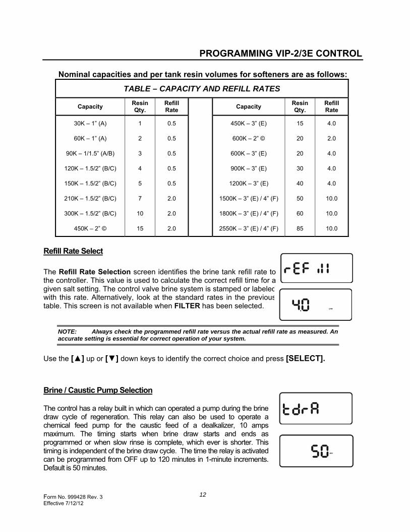
Nominal capacities and per tank resin volumes for softeners are as follows:
TABLE – CAPACITY AND REFILL RATES
Capacity Resin Qty.
Refill Rate
Capacity Resin Qty.
Refill Rate
30K – 1” (A)
60K – 1” (A)
90K – 1/1.5” (A/B)
120K – 1.5/2” (B/C)
150K – 1.5/2” (B/C)
210K – 1.5/2” (B/C)
300K – 1.5/2” (B/C)
450K – 2” ©
1
2
3
4
5
7
10
15
0.5
0.5
0.5
0.5
0.5
2.0
2.0
2.0
450K – 3” (E)
600K – 2” ©
600K – 3” (E)
900K – 3” (E)
1200K – 3” (E)
1500K – 3” (E) / 4” (F)
1800K – 3” (E) / 4” (F)
2550K – 3” (E) / 4” (F)
15
20
20
30
40
50
60
85
4.0
2.0
4.0
4.0
4.0
10.0
10.0
10.0
Refill Rate Select
The Refill Rate Selection screen identifies the brine tank refill rate to the controller. This value is used to calculate the correct refill time for a given salt setting. The control valve brine system is stamped or labeled with this rate. Alternatively, look at the standard rates in the previous table. This screen is not available when FILTER has been selected.
NOTE: Always check the programmed refill rate versus the actual refill rate as measured. An accurate setting is essential for correct operation of your system.
Use the [▲] up or [▼] down keys to identify the correct choice and press [SELECT].
Brine / Caustic Pump Selection The control has a relay built in which can operated a pump during the brine draw cycle of regeneration. This relay can also be used to operate a chemical feed pump for the caustic feed of a dealkalizer, 10 amps maximum. The timing starts when brine draw starts and ends as programmed or when slow rinse is complete, which ever is shorter. This timing is independent of the brine draw cycle. The time the relay is activated can be programmed from OFF up to 120 minutes in 1-minute increments. Default is 50 minutes.

Form No. 999428 Rev. 3 Effective 7/12/12
13
PROGRAMMING VIP-2/3E CONTROL
Caustic Feed Pump Activation – ( Dealkalizer only ) A caustic feed pump may be activated during brine draw, only if Dealkalizer is chosen under type of equipment. The caustic pump default is “no”, but can be turned on any time. The length of time that the pump is activated is equal to the time set in the tdrA screen. Answering “YES” to caustic also allows the control to calculate the capacity of the dealkalizer based on caustic addition. If the pump is off, the capacity calculated is based on sodium chloride only regenerations, which is approximately 30% less capacity than using salt and caustic. This screen will not appear if Filter or Softener is selected.
Demand Trip Point Variable Flow System Configuration
The Variable Demand Trip Point screen displays the trip point setting for VIP II/III Systems. When the average flow per tank exceeds this trip point, additional units will be brought into service. Provided the units have been in service for at least 30 minutes, when the average flow per tank drops below a computer defined percentage of this value, units will be taken out of service.
The trip point may be adjusted to meet each application’s specific need. The table below suggests trip point settings for various softener systems.
Suggested Demand Trip Point for VIP II/III Units (GPM/Tank)
Softener
Capacity GPM 30,000 6 60,000 12 90,000 18
120,000 24 210,000 27 300,000 45 450,000 59 600,000 94 900,000 120
1,200,000 145 1,500,000 165 1,800,000 190 2,550,000 200
NOTE: Values should be adjusted as required to meet the needs of each specific application. The table values are a suggestion only.

Form No. 999428 Rev. 3 Effective 7/12/12
14
PROGRAMMING VIP-2/3E CONTROL Turbine Select
The turbine selection screen displays the nominal size of the turbine being used by the unit. Five turbine size selections are available – ¾”, 1”, 11/2”, 2”, and ADJ
During periods of low flow, the computer will correct the flow meter readings to improve accuracy when a ¾”, 1”, 1 ½”, or 2” flow meter is used. If a different sensor is used, the setting ADJ must be selected. The control will prompt you to input the correct pulses per gallon value at the next screen.
Use the [▲] up or [▼] down keys to identify the correct choice and press [SELECT].
Turbine Adjustable Selection
If the “ADJ” setting was selected on the previous screen, the turbine pulses per gallon value must be programmed into the control. The tables in the appendix will be helpful in making the correct choice. Consult the factory if you have any questions. See Flow Sensor “K” Factors on page 21.
NOTE: If this is an initial programming sequence or if the model or system has been changed, programming will continue with the operating settings (second level select). If only configuration items (other than the model and system) have been changed; or, after a 4-minute idle period, the control will revert back to the Main Screen.

Form No. 999428 Rev. 3 Effective 7/12/12
15
PROGRAMMING VIP-2/3E CONTROL
Changing The Operating Settings (Second Level Select)
The Second Level select screens are accessed in two ways:
By Continuation After completing the third level select screens on an initial start-up, the control continues with second level select screens. Manual Entry Press and hold the [SELECT] button for 3 seconds to access the second level screens.
Hardness Selection – (Softeners Only)
Set the grains per gallon hardness of your water supply (determined by the water analysis or call your local water department).
Use the [▲] up arrow to increase the number and the [▼] down arrow to reduce the number. Each press of a button changes the display by 1, between 1 and 25. Between 25 and 125, the display changes by 5. Press and hold the buttons for fast advance. This screen is not available when FILTER is selected.
NOTE: To compensate for iron in the water supply, add 5 to the hardness number for each 1ppm of iron.
Total Exchangeable Anions – (Dealkalizer Only) Total Exchangeable Anions (TEA) is required when setting up a dealkalizer. Set the grains per gallon of the total exchangeable anions of the water supply (determined by the water analysis). Default is 20 grains.
Use the [▲] up button to increase the number and the [▼] down button to reduce the number. Each press of a button changes the display by 1, between 1 and 25. Between 25 and 125, the display changes by 5. Press and hold the buttons for fast advance. This screen is not available when Filter or Softener is selected.
Chlorides Selection – (Dealkalizer Only) The chloride content of the water being treated in conjunction with the total exchangeable anions is used to calculate the capacity of the dealkalizer. Chlorides are settable in increments of 1 from 0 to 25 grains and in increments of 5, between 25 and 100 grains. Default is 5 grains. This screen is not available when Filter or Softener is selected. Use the [▲] up or [▼] down buttons to identify the correct choice and press [SELECT].
Form No. 999428 Rev. 3 Effective 7/12/12
16
PROGRAMMING VIP-2/3E CONTROL
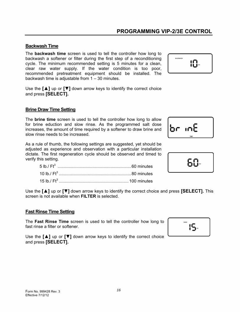
Backwash Time
The backwash time screen is used to tell the controller how long to backwash a softener or filter during the first step of a reconditioning cycle. The minimum recommended setting is 5 minutes for a clean, clear raw water supply. If the water condition is too poor, recommended pretreatment equipment should be installed. The backwash time is adjustable from 1 – 30 minutes.
Use the [▲] up or [▼] down arrow keys to identify the correct choice and press [SELECT].
Brine Draw Time Setting
The brine time screen is used to tell the controller how long to allow for brine eduction and slow rinse. As the programmed salt dose increases, the amount of time required by a softener to draw brine and slow rinse needs to be increased.
As a rule of thumb, the following settings are suggested, yet should be adjusted as experience and observation with a particular installation dictate. The first regeneration cycle should be observed and timed to verify this setting.
5 lb./ Ft3 ............................................................. 60 minutes
10 lb./ Ft3 ............................................................ 80 minutes
15 lb./ Ft3 .......................................................... 100 minutes
Use the [▲] up or [▼] down arrow keys to identify the correct choice and press [SELECT]. This screen is not available when FILTER is selected.
Fast Rinse Time Setting
The Fast Rinse Time screen is used to tell the controller how long to fast rinse a filter or softener.
Use the [▲] up or [▼] down arrow keys to identify the correct choice and press [SELECT].
Form No. 999428 Rev. 3 Effective 7/12/12
17
PROGRAMMING VIP-2/3E CONTROL
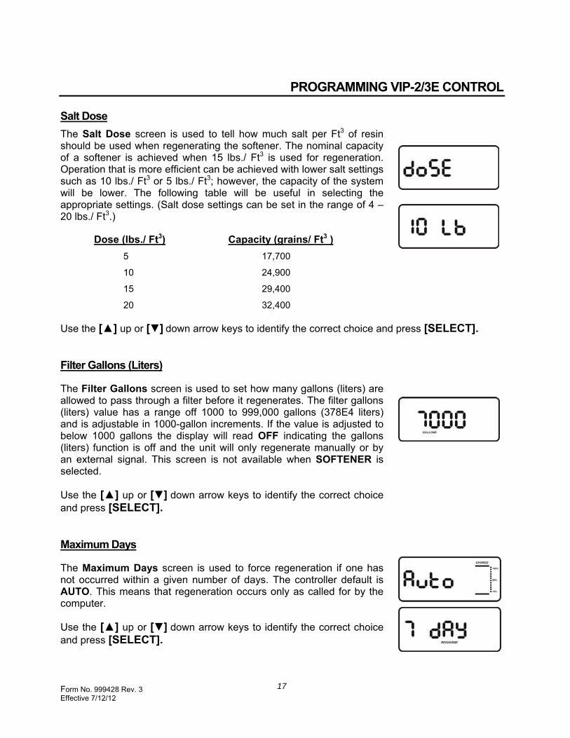
Salt Dose
The Salt Dose screen is used to tell how much salt per Ft3 of resin should be used when regenerating the softener. The nominal capacity of a softener is achieved when 15 lbs./ Ft3 is used for regeneration. Operation that is more efficient can be achieved with lower salt settings such as 10 lbs./ Ft3 or 5 lbs./ Ft3; however, the capacity of the system will be lower. The following table will be useful in selecting the appropriate settings. (Salt dose settings can be set in the range of 4 – 20 lbs./ Ft3.)
Dose (lbs./ Ft3) Capacity (grains/ Ft3 )
5 17,700
10 24,900
15 29,400
20 32,400
Use the [▲] up or [▼] down arrow keys to identify the correct choice and press [SELECT].
Filter Gallons (Liters)
The Filter Gallons screen is used to set how many gallons (liters) are allowed to pass through a filter before it regenerates. The filter gallons (liters) value has a range off 1000 to 999,000 gallons (378E4 liters) and is adjustable in 1000-gallon increments. If the value is adjusted to below 1000 gallons the display will read OFF indicating the gallons (liters) function is off and the unit will only regenerate manually or by an external signal. This screen is not available when SOFTENER is selected.
Use the [▲] up or [▼] down arrow keys to identify the correct choice and press [SELECT].
Maximum Days
The Maximum Days screen is used to force regeneration if one has not occurred within a given number of days. The controller default is AUTO. This means that regeneration occurs only as called for by the computer.
Use the [▲] up or [▼] down arrow keys to identify the correct choice and press [SELECT].
Form No. 999428 Rev. 3 Effective 7/12/12
18
SYSTEM DIAGNOSTICS
The VIP-2/3E Electronic Control offers an unprecedented amount of information and assistance for monitoring system performance and diagnosing system problems. The tools for accessing this information are reviewed in detail in the following sections – Automatic Diagnostics, Manual Diagnostics, and Service Center Diagnostics.
Initial Checkout Before moving to the more advanced tools, always perform the following initial checkout.
1. Is the display correct?
If the display is blank, check power.
If an error code is showing (Example: Er1-3), go to the Automatic Diagnostics section.
2. Are plumbing isolation valves fully open? Is the manual bypass valve fully closed?
3. Are power, control, and turbine cables installed correctly and securely?
4. Are inlet, outlet, and drain lines installed correctly?
5. Is there salt in the brine system? Is the brine tubing installed correctly? Has bridging occurred in the brine system? Does the valve draw and refill properly?
6. Is the hardness setting correct for your water supply? Has the hardness level changed since it was tested?
7. Is the control programmed correctly? Review and understand each of the programmed settings.
If you do not find the problem after making the initial check, go to the Manual Diagnostics section of this manual.
Automatic Diagnostics
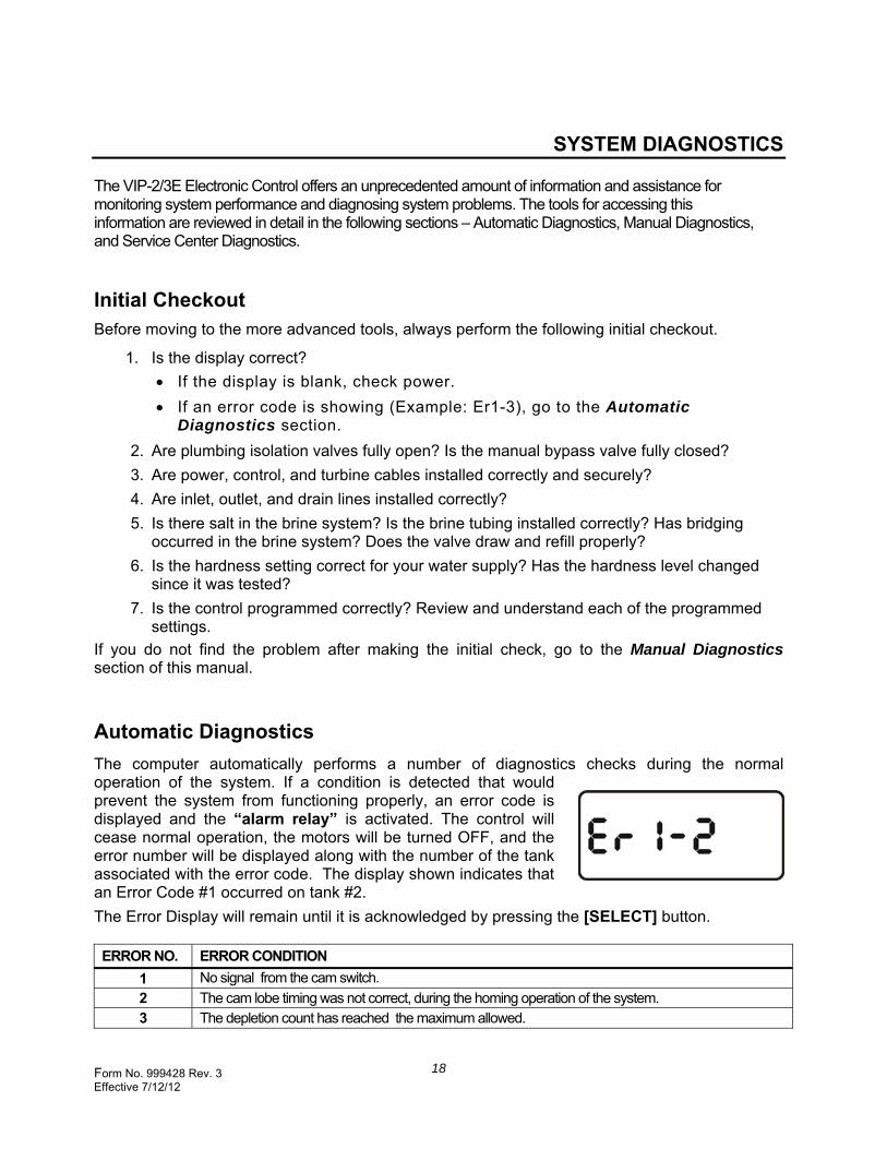
The computer automatically performs a number of diagnostics checks during the normal operation of the system. If a condition is detected that would prevent the system from functioning properly, an error code is displayed and the “alarm relay” is activated. The control will cease normal operation, the motors will be turned OFF, and the error number will be displayed along with the number of the tank associated with the error code. The display shown indicates that an Error Code #1 occurred on tank #2.
The Error Display will remain until it is acknowledged by pressing the [SELECT] button. ERROR NO. ERROR CONDITION
1 No signal from the cam switch.
2 The cam lobe timing was not correct, during the homing operation of the system. 3 The depletion count has reached the maximum allowed.
Form No. 999428 Rev. 3 Effective 7/12/12
19
SYSTEM DIAGNOSTICS
Description of ERROR CODES ERROR #1 : Error #1 will occur any time a signal from the cam switch is not received during positioning of the valve. The error will be detected either during homing of the valve or when positioning the valve during a regeneration. The controller will allow a grace period up to 150 seconds for a cam switch position change to be detected. If this error occurs, there is a problem with a broken or shorted wire, a motor is no longer operational, or the switch is broken. The control will stay in the Fourth Level Diagnostics until the problem is corrected and manually stepped out. The valves will then rotate to home position either stand-by or service. ERROR #2 : Error #2 can occur only during homing of the valves. This error indicates a problem in the timing of the switch closures as the cam rotates. There is a specific relation ship between the shortest distance a detent is detected and the longest distance a detent is detected. If this relationship is not detected, Error #2 is reported. There is a problem with the motor not running, a broken switch or a broken or shorted wire. The problem should be corrected and the control stepped out of the Fourth Level Diagnostics to restart the homing sequence. ERROR #3 : Error #3 is the depletion error. The control tracks the number of times a unit’s capacity is depleted. Error #3 is displayed when the number of depletions reaches 8 in total. Each time a depletion occurs, the control adds 1 to the total. Each time a unit is regenerated before it is depleted, the control subtracts 1 from the total. In normal operation, a unit will not be completely exhausted when it is triggered to regenerate. If the system is undersized, the units can not be regenerated fast enough, therefore depletions will occur. If the programming is not correct for a unit, this error could occur (check hardness, salt dosage, refill rate and resin quantity). Pressing [SELECT] will clear the error, transfer the control to the Fourth Level Diagnostics, and reset the depletion level on the unit to “0”. Only one tank is reported for each Error #3 message. If multiple tanks have a depletion count equal to 8, each will have a separate Error #3 message that must be cleared.
Suppressing an Alarm Condition The ALARM OUTPUT is activated when an ERROR occurs. An activated alarm can be temporarily suppressed by pressing the [REGEN] button while the error is displayed. The alarm will be deactivated for 60 seconds. Acknowledging an Error Pressing the [SELECT] button when an Error is displayed will acknowledge the error and temporarily deactivate the alarm and advance the control to Level 4 Diagnostics. The condition of each tank can be viewed. If the Error Code #3 was displayed, acknowledging the error will clear the error and reset the depletion code for that tank to “zero”. If Error Code #1 or #2 was displayed, the unit is taken “offline” and the control will advance to the Level 4 Diagnostics. The “offline” unit can be manually advanced for troubleshooting and correcting the cause for the ERROR. Leaving the Fourth Level Diagnostics screen will trigger the control to re-home all the valves in sequence.

Form No. 999428 Rev. 3 Effective 7/12/12
20
SYSTEM DIAGNOSTICS
Manual Diagnostics
The control functions are accessed through the Fourth Level Diagnostics screen. This screen is used to Manually Index Regeneration Cycles, diagnose problems with the turbine, valve position, outputs, and inputs. The Manual Diagnostics Screen can be accessed in two ways:
2) Pressing the [SELECT] key when an error code is showing 2) Fourth Level Diagnostics Screens Press and hold [SELECT] key for 3 seconds one time, repeat a second time, and then repeat a third time will open the Manual Diagnostics Screen.
Turbine Counts – A two or three-digit number on the left side of the display is the turbine count. This number will increment with each revolution of the turbine water meter. When a full gallon has counted, the digits will reset to zero and the beeper will sound. This verifies that the flow meter is functioning correctly.
Motor – The Motor segment will be displayed any time a valve motor is operating.
Switch Position – A “P” under the Valve Switches segments indicates that the position switch is closed. A “-” indicates that the switch is open.
Unit Number – A “1”, “2”, “3”, or “4” in the second position under the Valve Switches segments indicates the unit number to which the switch information applies.
Charge Bars – is used to indicate the position the valve.
Service – 0 bars
Backwash – 1 bar
Brine Draw / Rinse – 2 bars
Fast Rinse – 3 bars
Refill – 4 bars
Stand-by – 5 bars If the valve is in transition from one cycle to another the bar will flash. The charge bars do not show during initial homing of the system. RCHG – Indicates the unit is scheduled for regeneration. RECHARGE – Indicates the unit is in regeneration. (blinking). Colon – If this icon is “on”, the external regen input is activated.

Form No. 999428 Rev. 3 Effective 7/12/12
21
SYSTEM DIAGNOSTICS
Display All Segments
If the [▼] down arrow is depressed while in the manual diagnostics display, the controller turns on all display segments. This verifies the segments and that the button is working.
Online / Offline
If the [▲] up arrow is held while in Fourth Level Diagnostics, the “Online / Offline” status of a unit is displayed. Releasing the button advances the display to show the status of the next unit. Each press and release scrolls through the unit numbers.
If the [▲] up arrow is held and the [▼] down arrow is depressed, the unit is taken “Offline”. An “Offline” unit is ignored by the system and can be manually indexed through its regeneration steps individually by depressing the [Recharge] button. Only one unit can be manually designated as “Offline” at a time.
Press and hold the [▲] up arrow and then the [▼] down arrow a second time to bring the unit back “Online”. If the unit is in regeneration, the regeneration will continue and the unit will return to normal operation.
Manually Cycle a Unit through Regeneration
Advance the control to Fourth Level Diagnostics. Take the unit to be manually advanced “Offline”. Press and hold the [REGEN] button for 3 seconds. The unit will advance to the backwash cycle. After the unit is in backwash, press the [REGEN] button again and the unit will advance to the next cycle. This can be continued until the unit has returned to service. Once in service, the unit can be put back “Online”. This function can be used to manually advance a valve through the reconditioning cycle to check valve operation in each step.
Form No. 999428 Rev. 3 Effective 7/12/12
22
CONTROL OUTPUTS
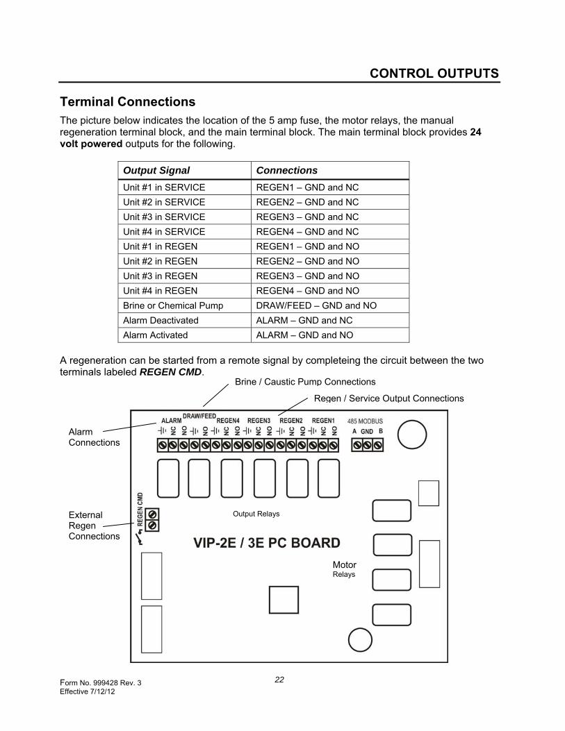
Terminal Connections The picture below indicates the location of the 5 amp fuse, the motor relays, the manual regeneration terminal block, and the main terminal block. The main terminal block provides 24 volt powered outputs for the following.
Output Signal Connections
Unit #1 in SERVICE REGEN1 – GND and NC
Unit #2 in SERVICE REGEN2 – GND and NC
Unit #3 in SERVICE REGEN3 – GND and NC
Unit #4 in SERVICE REGEN4 – GND and NC
Unit #1 in REGEN REGEN1 – GND and NO
Unit #2 in REGEN REGEN2 – GND and NO
Unit #3 in REGEN REGEN3 – GND and NO
Unit #4 in REGEN REGEN4 – GND and NO
Brine or Chemical Pump DRAW/FEED – GND and NO
Alarm Deactivated ALARM – GND and NC
Alarm Activated ALARM – GND and NO
A regeneration can be started from a remote signal by completeing the circuit between the two terminals labeled REGEN CMD.
External Regen Connections
Alarm Connections
Motor Relays
Output Relays
Brine / Caustic Pump Connections
Regen / Service Output Connections

Form No. 999428 Rev. 3 Effective 7/12/12
23
FLOW METER CALIBRATION
Flow Sensor “K” Factors The “K” Factor the different size Flow Sensors are listed in the table below. The “K” Factors used in the VIP Control are built into it’s algorithm for the .75”, 1”, 1.5” and 2” Flow Meters. The “K” Factor for a flow meter is the number of pulses per gallon of water. If ADJ is selected, then the VIP has the capability to accept the “K” Factor from any Flow Meter with a square wave signal output. Signet Paddle Wheel Model 2536 is one such meter. The Tables below provide the “K” Factor associated with the various sizes and types of pipe available.
Type of Sensor Pipe Size Pulses Per Gallon (“K” Factor)
VIP PVC & Brass
.75” 200
1” 100
1.5” 46
2” 46
Signet 2536 and
Iron Pipe
Sch 40 Pipe Sch 80 Pipe
1” Tee 287 -
1.5” Tee 91 -
2” Tee 54 -
2” Saddle 54 65
3” Saddle 23.2 26
4” Saddle 13.3 14.7
Signet 2536 and
PVC Pipe
Sch 40 Pipe Sch 80 Pipe
1” Tee - 352
1.5” Tee - 117
2” Tee - 67
2” Saddle 55 67
3” Saddle 23.7 27
4” Saddle 13.5 15
Signet 2536
and
Copper Pipe
Type K Type L Type M
3” Tee 28 27 26
4” Tee 15.8 15.2 14.9

Form No. 999428 Rev. 3 Effective 7/12/12
24
1890 Woodlane DriveWoodbury, MN 55125