vision™ oplc™ v130 com modules: v100-17-can, … · only qualified service personnel should...
TRANSCRIPT

Unitronics
Vision™ OPLC™ V130 COM Modules: V100-17-CAN, V100-17-RS4/X, V100-17-ET2
This guide shows you how to install an additional communication module in a V130 controller. Instructions and technical specifications are included for modules: V100-17-CAN (CANbus) V100-17-RS4 (RS232/RS485, not isolated) V100-17-RS4X (RS232/RS485, isolated) V100-17-ET2 (Ethernet)
Danger Symbols When any of the following symbols appear, read the associated information carefully. Symbol Meaning Description
Danger The identified danger causes physical and property damage.
Warning The identified danger could cause physical and property damage.
Caution Caution Use caution.
Before using this product, the user must read and understand this document. All examples and diagrams are intended to aid understanding, and do not guarantee operation.
Unitronics accepts no responsibility for actual use of this product based on these examples. Please dispose of this product according to local and national standards and regulations. Only qualified service personnel should open this device or carry out repairs.
Failure to comply with appropriate safety guidelines can cause severe injury or property damage.
Do not attempt to use this device with parameters that exceed permissible levels. To avoid damaging the system, do not connect/disconnect the device when power is on.
Environmental Considerations
Do not install in areas with: excessive or conductive dust, corrosive or flammable gas, moisture or rain, excessive heat, regular impact shocks or excessive vibration.
Do not place in water or let water leak onto the unit. Do not allow debris to fall inside the unit during installation.
General
Turn off power before making communications connections. Do not touch live wires
Unused pins should not be connected. Ignoring this directive may damage the device. Double-check all wiring before turning on the power supply.
9/07 V130 COM Modules: V100-17-CAN, V100-17-RS4/X, V100-17-ET2
2 Unitronics
Installation Instructions
This section comprises all of the installation procedures for each of the modules.
Caution Installing modules also requires you to remove and replace PCB boards already
installed in the controller. Make certain that the pins fit correctly into their matching receptacle.
Opening the Controller
Before performing these actions, touch a grounded object to discharge any electrostatic charge.
Avoid touching the PCB board directly. Hold the PCB board by its connectors.
1. Turn off the power supply, disconnect, and dismount the controller. 2. The back cover of the controller comprises 4 screws, located in the corners. Remove the screws,
and pull off the back cover.
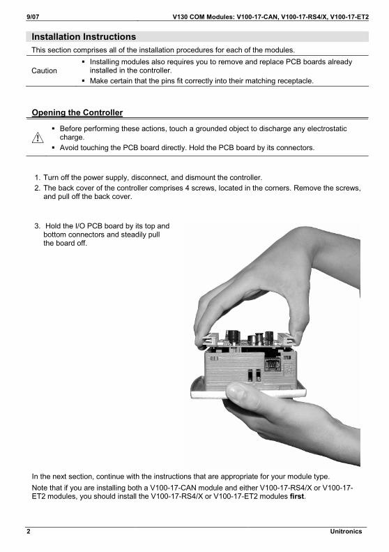
3. Hold the I/O PCB board by its top and
bottom connectors and steadily pull the board off.
In the next section, continue with the instructions that are appropriate for your module type. Note that if you are installing both a V100-17-CAN module and either V100-17-RS4/X or V100-17-ET2 modules, you should install the V100-17-RS4/X or V100-17-ET2 modules first.

Installation Guide 9/07
Unitronics
Installing V100-17-CAN (CANbus)1. Remove the plastic tab marked X. 2. Plastic tab X comprises a cutout that covers
the CANbus port location. Snip through the cutout holders and remove the cutout.
3. On the V100-17-CAN, locate the: - white plastic pin. The main board comprises an insertion point for this pin. - 6-pin female CANbus connector. The main board comprises a male 6-pin CANbus connector.
4. Insert the module as shown in the accompanying figure.
Caution Make certain that the pins fit
correctly into their matching receptacle.
5. When the module is properly installed in the controller, it is held in place by the white plastic pin.

9/07 V130 COM Modules: V100-17-CAN, V100-17-RS4/X, V100-17-ET2
4 Unitronics
6. Replace the plastic tab marked X and then close the controller as shown on page 6.
Note that in order to remove the module, you must compress the ends of the white pin with a pair of pliers while pulling the module out of the controller.
Installing V100-17-RS4/X (RS232/RS485)/ V100-17-ET2 (Ethernet)The installation procedure for both modules is nearly identical.
1. Remove the plastic tabs marked X and Y. Note that if the controller already contains a V100-17-CAN, you must remove it.
2. Next, remove the ribbon cable shown in the accompanying figure.
a. Press the sides of the cable connector and pull it slightly upwards; this releases the cable.
b. Pull the cable from the board. 3. Locate the two screws that fasten the board to
the controller and remove them.

Installation Guide 9/07
Unitronics
4. Hold the main board by Port 1 and by the I/O expansion port, and pull it out of the controller.
5. Remove the plastic tab marked A and B, and then break the tab in two.
6. Install the module as shown in the accompanying figure.
9/07 V130 COM Modules: V100-17-CAN, V100-17-RS4/X, V100-17-ET2
6 Unitronics
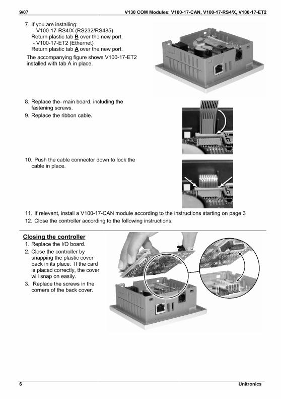
7. If you are installing: - V100-17-RS4/X (RS232/RS485) Return plastic tab B over the new port. - V100-17-ET2 (Ethernet) Return plastic tab A over the new port.
The accompanying figure shows V100-17-ET2 installed with tab A in place.
8. Replace the- main board, including the fastening screws.
9. Replace the ribbon cable.
10. Push the cable connector down to lock the cable in place.
11. If relevant, install a V100-17-CAN module according to the instructions starting on page 3 12. Close the controller according to the following instructions.
Closing the controller1. Replace the I/O board. 2. Close the controller by
snapping the plastic cover back in its place. If the card is placed correctly, the cover will snap on easily.
3. Replace the screws in the corners of the back cover.

Installation Guide 9/07
Unitronics
Module Information and Specifications
V100-17-CAN (CANbus module)Use this CANbus module to create a decentralized control network using CAN protocols: CANopen: 127 controllers or external devices Unitronics’ proprietary UniCAN: 60 controllers, (512 data bytes per scan) The CANbus port is galvanically isolated.
Standard Kit contents
V100-17-CAN 5-pin CANbus connectorTermination resistor
CANbus Wiring
Network terminators. Place terminators at each end of the CANbus network
Resistance must be set to 1%, 121Ω, 1/4W
Connect ground signal to the earth at only one point, near the power supply
The network power supply need not be at the end of the network
CANbus Connector
121terminating
resistor
121terminating
resistor
Circuitprotectiondevice
+-
24V PowerSupply
-V
L
H
+V
PE
-V
L
H
+V
PE
-V
L
H+V
PE

9/07 V130 COM Modules: V100-17-CAN, V100-17-RS4/X, V100-17-ET2
8 Unitronics
V100-17-CAN Technical Specifications CANbus port 1
Nodes CANopen Unitronics’ CANbus protocols 127 60
Power requirements 24VDC (±4%), 40mA max. per unit Galvanic isolation Yes, between CANbus and controller
Cable type Twisted-pair; DeviceNet® thick shielded twisted pair cable is recommended.
Cable length/baud rate 25 m 100 m 250 m 500 m 500 m 1000 m* 1000 m*
1 Mbit/s 500 Kbit/s 250 Kbit/s 125 Kbit/s 100 Kbit/s 50 Kbit/s 20 Kbit/s
* If you require cable lengths over 500 meters, contact technical support.
Weight 9.2g (0.32 oz)
Installation Guide 9/07
Unitronics
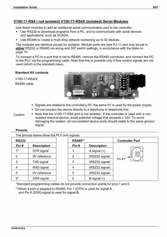
V100-17-RS4 ( not isolated) V100-17-RS4X (isolated) Serial ModulesUse these modules to add an additional serial communication port to the controller. Use RS232 to download programs from a PC, and to communicate with serial devices
and applications, such as SCADA. Use RS485 to create a multi-drop network containing up to 32 devices. The modules are identical except for isolation. Module ports are type RJ-11 and may be set to either RS232 or RS485 via wiring and DIP switch settings, in accordance with the table on page 10. To connect a PC to a port that is set to RS485, remove the RS485 connector, and connect the PC to the PLC via the programming cable. Note that this is possible only if flow control signals are not used (which is the standard case).
Standard Kit contents
V100-17-RS4/X RS485 cable
Caution
Signals are related to the controller’s 0V; the same 0V is used by the power supply. Do not connect the device directly to a telephone or telephone line. Note that the V100-17-RS4 port is not isolated. If the controller is used with a non-
isolated external device, avoid potential voltage that exceeds ± 10V. To avoid damaging the system, all non-isolated device ports should relate to the same ground signal.
Pinouts The pinouts below show the PLC port signals.
RS232 RS485** Controller Port Pin # Description Pin # Description 1* DTR signal 1 A signal (+)
2 0V reference 2 (RS232 signal)
3 TXD signal 3 (RS232 signal)
4 RXD signal 4 (RS232 signal)
5 0V reference 5 (RS232 signal)
6* DSR signal 6 B signal (-)
Pin #1
*Standard programming cables do not provide connection points for pins 1 and 6. **When a port is adapted to RS485, Pin 1 (DTR) is used for signal A, and Pin 6 (DSR) signal is used for signal B.

9/07 V130 COM Modules: V100-17-CAN, V100-17-RS4/X, V100-17-ET2
10 Unitronics
RS232 to RS485: Changing DIP Switch Settings
The port is set to RS232, termination ON, by factory default.
Switch Settings 1 2 3 4 5 6
RS232* ON ON OFF OFF ON ON RS485 OFF OFF ON ON OFF OFF RS485 with termination**
ON ON ON ON OFF OFF
*Default factory setting **Causes the unit to function as an end unit in an RS485 network
V100-17-RS4/X Technical Specifications
RS232 Port Specifications Voltage limits ±20V
Input voltage ±20VDC absolute maximum Cable length 15m maximum (50 feet)
RS485 Port Specifications Input Voltage -7 to +12V differential max. Cable type Shielded twisted pair, in compliance with EIA RS485 Cable length 1200m maximum (4000 feet) Baud rate 300– 115,200 bps Nodes Up to 32
Isolation V100-17-RS4 No V100-17-RS4-X Yes
Weight V100-17-RS4/X 12.6g (0.44 oz)

Installation Guide 9/07
Unitronics
V100-17-ET2 (Ethernet)Use this module to add an Ethernet port to the controller and implement communications via TCP/IP, such as MODBUS over TCP. Standard Kit contents
V100-17-ET2
RJ45 Connector Pinout Ethernet LEDS
Pin # Description LED Function 1 T+ = Positive transmit signal 2 T- = Negative transmit signal
Green (LNK)
ON when link exists
3 R+ = Positive receive signal 6 R- = Negative receive signal
Yellow (ACT)
Blinks during RX/TX
Ethernet Connections Controller to hub/switch connection Controller to controller connection Controller Hub/Switch Controller Controller Pin # Function Pin # Function Pin # Function Pin # Function1 T+ 1 T+ 1 T+ 3 R+ 2 T- 2 T- 2 T- 6 R- 3 R+ 3 R+ 3 R+ 1 T+ 6 R- 6 R- 6 R- 2 T-
:
V100-17-ET2 Technical Specifications Port type RJ45 Transmission speed 10/100Mbps Star Topology Network topology Star, based on external hub/switch Cable type Category 5 STP (shielded twisted
pair) is recommended; UTP (unshielded twisted pair) may also be used
Drop line length Up to 100 meters, controller to hub/switch or controller to controller.
Weight 22g (0.77 oz)

9/07 V130 COM Modules: V100-17-CAN, V100-17-RS4/X, V100-17-ET2
12 Unitronics
The information in this document reflects products at the date of printing. Unitronics reserves the right, subject to all applicable laws, at any time, at its sole discretion, and without notice, to discontinue or change the features, designs, materials and other specifications of its products, and to either permanently or temporarily withdraw any of the forgoing from the market. All information in this document is provided "as is" without warranty of any kind, either expressed or implied, including but not limited to any implied warranties of merchantability, fitness for a particular purpose, or non-infringement. Unitronics assumes no responsibility for errors or omissions in the information presented in this document. In no event shall Unitronics be liable for any special, incidental, indirect or consequential damages of any kind, or any damages whatsoever arising out of or in connection with the use or performance of this information. The tradenames, trademarks, logos and service marks presented in this document, including their design, are the property of Unitronics (1989) (R"G) Ltd. or other third parties and you are not permitted to use them without the prior written consent of Unitronics or such third party as may own them
DSP-V100-COM 09/07