jazz™ oplc™ user guide - · pdf file5 preface jazz™ oplc™ user guide...
TRANSCRIPT

2/2006 JZ10-21-G20
User Guide
No part of this document may be used for any purpose other than for the purposes specifically indicated herein nor may it be reproduced or transmitted in any form or by any means, electronic or mechanical, including photocopying and/or recording, for any purpose without written permission from Unitronics.
The information appearing in this document is for general purposes only. Unitronics makes no warranty of any kind with regard to the information appearing in this document, including, but not limited to, implied warranties of merchantability and/or fitness for a particular use or purpose. Unitronics assumes no responsibility for the results, direct and/or indirect, of any misuse of the information appearing in this document nor for any use of the Unitronics products referred to herein in any manner deviating from the recommendations made in this document. Unitronics assumes no responsibility for the use of any parts, components, or other ancillary appliances including circuitry other than as recommended hereunder or other than that embodied in the Unitronics product.
Unitronics retains all rights to its proprietary assets including, but not limited to its software products which are copyrighted and shall remain the property of Unitronics. Copyright protection claimed includes all Forms and matters of copyrightable materials and information legally allowed including but not limited to material generated from the software programs which are displayed on the screen of the Unitronics products such as styles, templates, icons, screen displays, looks, etc. Duplication and/or any unauthorized use thereof are strictly prohibited without prior written permission from Unitronics.
All brand or product names are used for identification purpose only and may be trademarks or registered trademarks of their respective holders.
Unitronics reserves the right to revise this publication from time to time and to amend its contents and related hardware and software at any time. Technical updates (if any) may be included in subsequent editions (if any).
5
Preface Jazz™ OPLC™ User Guide
This guide contains essential information for Jazz™ OPLC™ users. Note that illustrations showing the Jazz™ OPLC™ refer to all Jazz™ OPLC™ models, except where otherwise specified. Warnings and Safety Guidelines Read this section carefully before installing and operating the device. Chapter 1: Overview Contains a general description of the device’s features and functions. Chapter 2: Mounting Describes mounting considerations and procedures. Chapter 3: Power Supply Explains wiring procedures and considerations. Chapter 4: I/Os Presents I/O options. Chapter 5: Customizing the HMI Panel Customize the operating panel by labeling the keyboard keys. Chapter 6: Information Mode Describes how to use Information Mode to view runtime values, view and set RTC values, reset and initialize the controller, and check I/O module status. Appendix A: New PLC Users Provides information for new PLC users.

7
Table of Contents Preface 5 Warnings and Safety Guidelines 9
Guidelines for user safety and equipment protection............................................................9 Warnings .............................................................................................................................10
Chapter 1: Overview 11 Introducing the Jazz™ OPLC™............................................................................................11
Chapter 2: Mounting 15 Before You Begin ................................................................................................................15 Panel Mounting....................................................................................................................17 DIN-Rail Mounting ...............................................................................................................18
Chapter 3: Power Supply 19 Power Supply ......................................................................................................................19 Safety Considerations .........................................................................................................19 Wiring the Power Supply .....................................................................................................19
Chapter 4: I/Os 21 Wiring Considerations .........................................................................................................21 On-board I/Os......................................................................................................................21 I/O Options: According to Model .........................................................................................22
Chapter 5: Customizing the HMI Panel 25 Labeling Slides ....................................................................................................................25
Chapter 6: Information Mode 27 Using Information Mode ......................................................................................................27
Appendix A: New PLC Users 29 Parts of a PLC .....................................................................................................................29 How PLCs Work ..................................................................................................................29
Table of Figures 31


9
Warnings and Safety Guidelines Guidelines for user safety and equipment protection
This manual is intended to aid trained and competent personnel in the installation of this equipment as defined by the European directives for machinery, low voltage, and EMC. Only a technician or engineer trained in the local and national electrical standards should perform tasks associated with the electrical wiring of this device. Symbols are used to highlight information relating to the user’s personal safety and protection of the equipment throughout this manual. When any of the following symbols appear, the associated information must be read carefully and understood fully.
Danger Symbols
Symbol Meaning Description
Titl Danger
The identified danger causes physical and property damage.
Warning
The identified danger could cause physical and property damage.
Caution Caution Use caution.

Jazz™ OPLC™ User Guide
10
Warnings • Under no circumstances will Unitronics be liable or responsible for any consequential
damage that may arise as a result of installation or use of this equipment.
• All examples and diagrams shown in the manual are intended to aid understanding. They do not guarantee operation.
• Unitronics accepts no responsibility for actual use of this product based on these examples.
• Due to the great variety of possible applications for this equipment, the user must assess the suitability of this product for specific applications.
• Make sure to have safety procedures in place to stop any connected equipment in a safe manner if the controller should malfunction or become damaged for any reason.
• Do not replace electrical parts or try to repair this product in any way.
• Only qualified service personnel should open the device’s housing or carry out repairs.
• The manufacturer is not responsible for problems resulting from improper or irresponsible use of this device.
• Please dispose of this product in accordance with local and national standards and regulations.
• Before using this product, check all product documentation, such as the product’s installation guide and technical specifications, for safety guidelines and other relevant information.

11
Chapter 1: Overview Introducing the Jazz™ OPLC™1
The Jazz™ OPLC™ is a micro OPLC; a compact PLC controller that contains a fully integrated operating panel and an on-board I/O configuration. Economically priced, Jazz™ OPLC™ does everything a ‘smart relay’ can—plus benefits your application with full PLC functionality and a flexible operator interface.
Figure 1. The Jazz™ OPLC
You can obtain updated information regarding specific Jazz™ options from local Unitronics distributors, or the company website located at: http://www.unitronics.com/jazz.htm .
1 Acronym for Operating panel + Programmable Logic Controller
Jazz™ OPLC™ User Guide
12
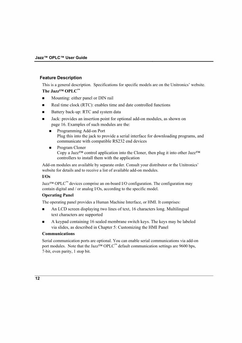
Feature Description This is a general description. Specifications for specific models are on the Unitronics’ website. The Jazz™ OPLC™
Mounting: either panel or DIN rail Real time clock (RTC): enables time and date controlled functions Battery back-up: RTC and system data Jack: provides an insertion point for optional add-on modules, as shown on
page 16. Examples of such modules are the: Programming Add-on Port
Plug this into the jack to provide a serial interface for downloading programs, and communicate with compatible RS232 end devices
Program Cloner Copy a Jazz™ control application into the Cloner, then plug it into other Jazz™ controllers to install them with the application
Add-on modules are available by separate order. Consult your distributor or the Unitronics’ website for details and to receive a list of available add-on modules. I/Os Jazz™ OPLC™ devices comprise an on-board I/O configuration. The configuration may contain digital and / or analog I/Os, according to the specific model. Operating Panel The operating panel provides a Human Machine Interface, or HMI. It comprises:
An LCD screen displaying two lines of text, 16 characters long. Multilingual text characters are supported
A keypad containing 16 sealed membrane switch keys. The keys may be labeled via slides, as described in Chapter 5: Customizing the HMI Panel
Communications Serial communication ports are optional. You can enable serial communications via add-on port modules. Note that the Jazz™ OPLC™ default communication settings are 9600 bps, 7-bit, even parity, 1 stop bit.
Chapter 1: Overview
13
Programming Unitronics’ U90 Ladder programming software enables you to create both your Jazz™ PLC and HMI applications in a single PC environment. Jazz™ programming kits such as the JZ-PRG Kit supply the elements you need in order to build and install Jazz™ applications. These elements include U90 Ladder software plus other software utilities, such as Remote Access and DataXport. The kit also includes a serial add-on port module, adapter, and the cable required for PC-PLC application download. PLC Ladder application
Enables Jazz™ to perform its control tasks Ladder code memory: 24K (virtual) Easy to build: simple drag-and-drop functions such as compare, logic, math,
store, clock, and loops Supports special functions such as Immediate Read/Write and MODBUS
communications via system bits and integers HMI application
Customizes your Jazz™ operator interface Enables you to create up to 60 displays and conditionally display status
messages, error messages, and instructions on the Jazz™ LCD screen Displays variable values for bits, integers, timers, times, dates, I/O status, and
conditional text Assigns functions to the Jazz™ keypad keys Enables the operator to enter information via the Jazz™ keypad
Jazz™ OPLC™ User Guide
14
Safety Guidelines
• Failure to comply with appropriate safety guidelines can result in
severe personal injury or property damage. Always exercise proper caution when working with electrical equipment.
• Check the user program before running it.
• Do not attempt to use the controller with voltage exceeding permissible levels. Permissible voltage levels are listed in the device’s technical specifications.
• Install an external circuit breaker and take all appropriate safety measures against short-circuiting in external wiring.
Caution • Ascertain that terminal blocks are properly secured in place.

15
Chapter 2: Mounting This chapter gives mounting instructions.
Before You Begin Before you begin installation procedures, check the Jazz™ OPLC™ package contents. Standard packages contain the Jazz™ OPLC™, green plastic plug-in connectors and 4 mounting brackets, each with a screw inserted for panel mounting. These elements are illustrated in Figure 2 below. The kit also includes a gasket that you should seat in back of the operating panel before panel-mounting the unit. Note that keypad slides are already inserted behind the operating panel’s faceplate.
Figure 2. Jazz™ OPLC™, Connectors, Brackets, and Gasket
Please note that detailed dimensions are given in the product’s installation guide.
Jazz™ OPLC™ User Guide
16
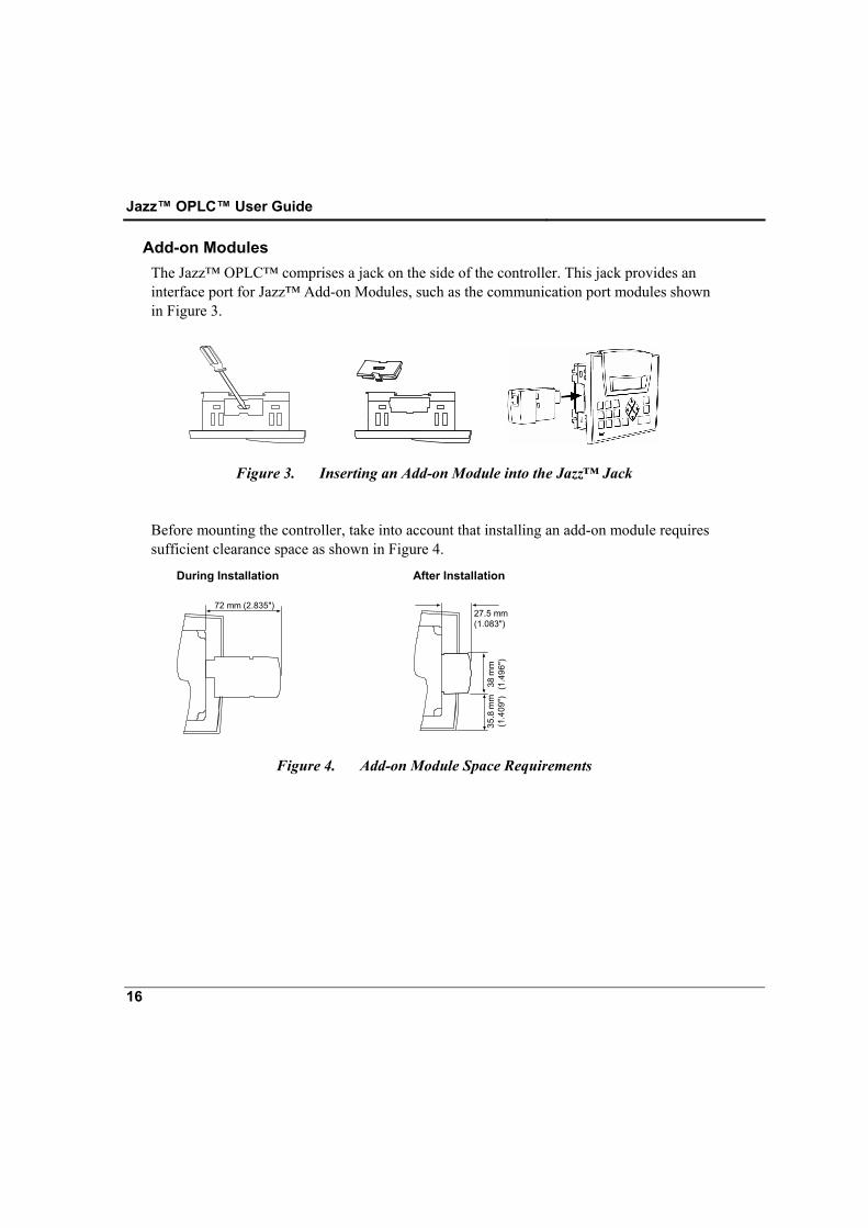
Add-on Modules The Jazz™ OPLC™ comprises a jack on the side of the controller. This jack provides an interface port for Jazz™ Add-on Modules, such as the communication port modules shown in Figure 3.
Figure 3. Inserting an Add-on Module into the Jazz™ Jack
Before mounting the controller, take into account that installing an add-on module requires sufficient clearance space as shown in Figure 4.
During Installation After Installation
72 mm (2.835")
27.5 mm(1.083")
38 m
m(1
. 496
" )35
. 8 m
m(1
. 409
" )
Figure 4. Add-on Module Space Requirements
Chapter 2: Mounting
17
Safety and Environmental Guidelines
• Do not install in areas with: excessive or conductive dust, corrosive or
flammable gas, moisture or rain, excessive heat, regular impact shocks or excessive vibration.
• Do not place in water or let water leak onto the controller.
• Do not allow debris to fall inside the unit during installation.
• Double-check all the wiring before turning on the power supply.
• Do not touch live wires.
• Stay as far as possible from high-voltage cables and power equipment.
• Leave a minimum of 10mm space for ventilation between the top and bottom edges of the controller and the enclosure walls.
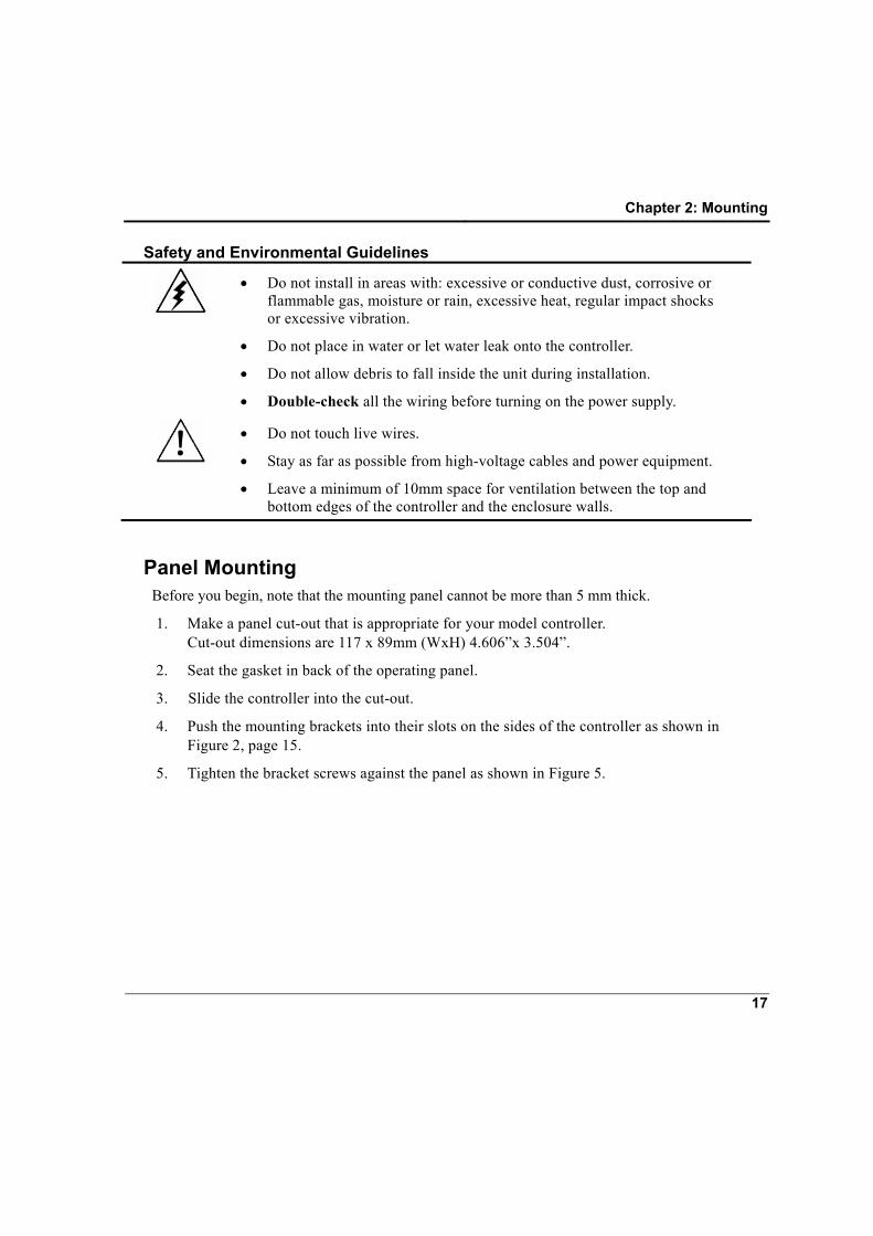
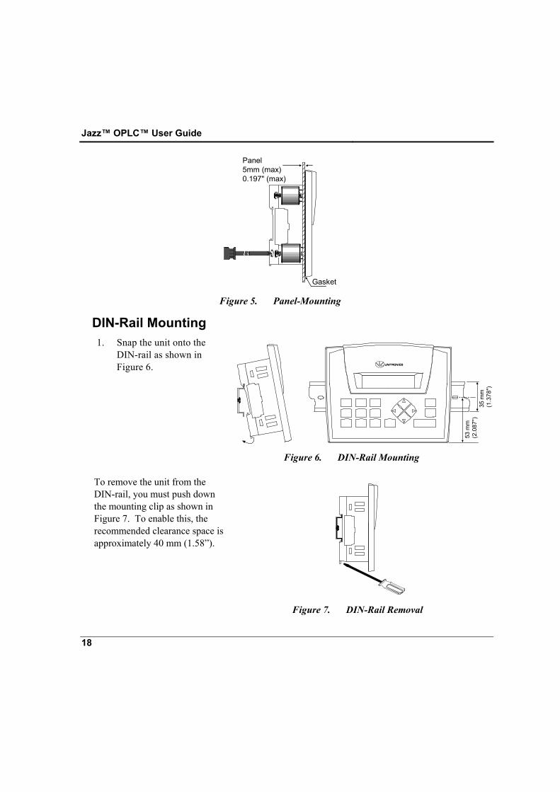
Panel Mounting Before you begin, note that the mounting panel cannot be more than 5 mm thick.
1. Make a panel cut-out that is appropriate for your model controller. Cut-out dimensions are 117 x 89mm (WxH) 4.606”x 3.504”.
2. Seat the gasket in back of the operating panel.
3. Slide the controller into the cut-out.
4. Push the mounting brackets into their slots on the sides of the controller as shown in Figure 2, page 15.
5. Tighten the bracket screws against the panel as shown in Figure 5.
Jazz™ OPLC™ User Guide
18
Gasket
Panel5mm (max)0.197" (max)
Figure 5. Panel-Mounting
DIN-Rail Mounting 1. Snap the unit onto the
DIN-rail as shown in Figure 6.
35 m
m(1
.378
")
53 m
m(2
.087
")
..
Figure 6. DIN-Rail Mounting
To remove the unit from the DIN-rail, you must push down the mounting clip as shown in Figure 7. To enable this, the recommended clearance space is approximately 40 mm (1.58”).
Figure 7. DIN-Rail Removal
19
Chapter 3: Power Supply Power Supply
The controller requires an external power supply in accordance with the controller’s technical specifications. You must use an external circuit protection device as shown in Figure 8, page 20.
Safety Considerations
• Do not touch live wires.
• A non-isolated power supply can be used provided that a 0V signal is connected to the chassis.
• Standard safety considerations require that metal cabinet panels be earthed to avoid electrocution.
• Do not connect either the ‘Neutral or ‘Line’ signal of the
110/220VAC to the device’s 0V pin.
• In the event of voltage fluctuations or non-conformity to voltage power supply specifications, connect the device to a regulated power supply.
• The wiring of this device is specifically designed to be safe and easy. A technician or engineer trained in the local and national electrical standards should perform all tasks associated with the electrical wiring of the device.
• Double-check all wiring before turning on the power supply.
Wiring the Power Supply
• Do not use tin, solder, or any other substance on the stripped wire
that might cause the wire strand to break.
• Install at maximum distance from high-voltage cables and power equipment.
• To avoid damaging the wire, do not exceed a maximum torque of 0.5 N·m (5 kgf·cm).
Jazz™ OPLC™ User Guide
20
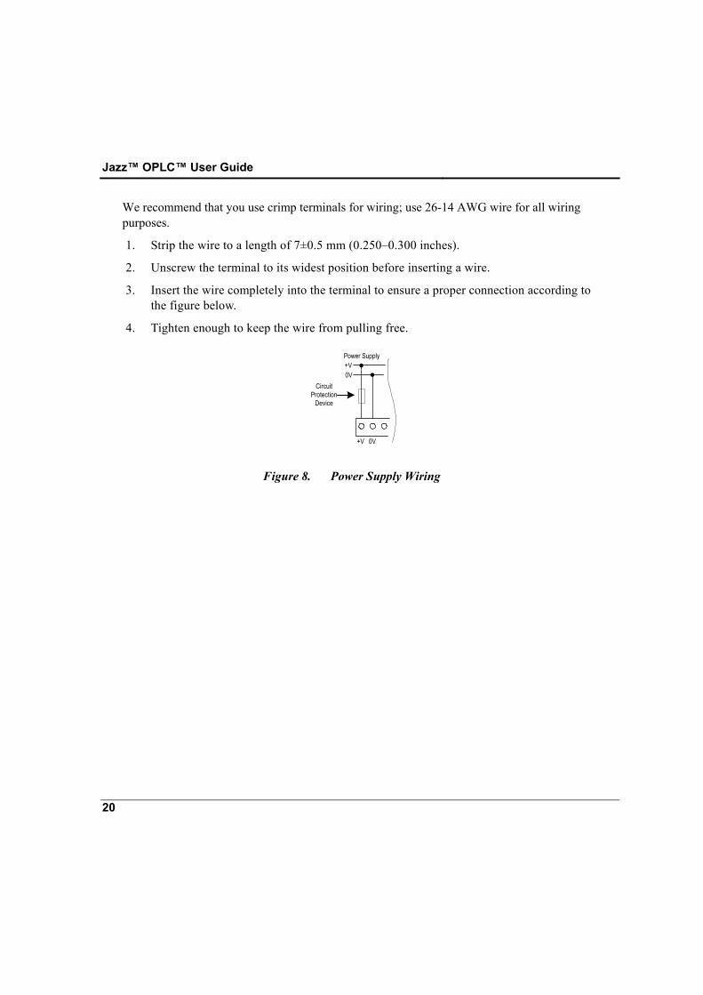
We recommend that you use crimp terminals for wiring; use 26-14 AWG wire for all wiring purposes.
1. Strip the wire to a length of 7±0.5 mm (0.250–0.300 inches).
2. Unscrew the terminal to its widest position before inserting a wire.
3. Insert the wire completely into the terminal to ensure a proper connection according to the figure below.
4. Tighten enough to keep the wire from pulling free.
0V+V
+V 0V
Power Supply
CircuitProtection
Device
Figure 8. Power Supply Wiring
21
Chapter 4: I/Os The controller offers an on-board I/O configuration which varies according to the controller model. The configuration may contain analog and/or digital I/Os.
Wiring Considerations • A technician or engineer trained in the local and national
electrical standards should perform all tasks associated with the electrical wiring of the controller.
• Input or output cables should not be run through the same multi-core cable or share the same wire.
• Do not lay input/output cables near high voltage power cables.
• Allow for voltage drop and noise interference with input/output lines used over an extended distance. Please use wire that is properly sized for the current load.
• Double-check all the wiring before turning on the power supply.
• Unused pins should not be connected. Ignoring this directive may damage the controller.
On-board I/Os I/O Connectors
I/O connection points are provided by external connectors at the top and bottom of the controller. The connectors plug in, enabling quick, easy removal. They provide screw-type connection points for the power source, inputs, and outputs. The connection points are clearly labeled on the controller itself. The top connector generally provides connections for the power supply, analog and / or digital inputs and high-speed counter. The bottom connector generally provides analog and / or digital output connection points.
Jazz™ OPLC™ User Guide
22
Connecting I/Os 1. Strip the wire to a length of 7±0.5mm (0.250–0.300 inches).
2. Unscrew the terminal to its widest position before inserting a wire.
3. Insert the wire completely into the terminal to ensure a proper connection.
4. Tighten enough to keep the wire from pulling free.
Wire Size and Specifications
• Wire the inputs and outputs using 26-14 AWG wire.
• To avoid damaging the wire, do not exceed a maximum torque of 0.5 N·m (5 kgf·cm).
• Do not use tin, solder, or any other substance on the stripped wire that might cause the wire strand to break.
• We recommend that you use crimp terminals for wiring.
I/O Options: According to Model Technical specifications regarding specific I/O configurations may be found on the company website’s technical library, or on the Setup CD generally included with programming kits.
Digital Inputs Depending on your controller model, inputs may be set to pnp (source) or npn (sink) via settings and appropriate wiring. Input values are placed in operands represented by the letter “I” when you write your program. They are numbered from 0.
High-Speed Counter According to your controller model, certain inputs may be able to function as either a high-speed counters or as normal digital inputs.
Chapter 4: I/Os
23
Analog I/Os Specific controller models contain analog I/Os.
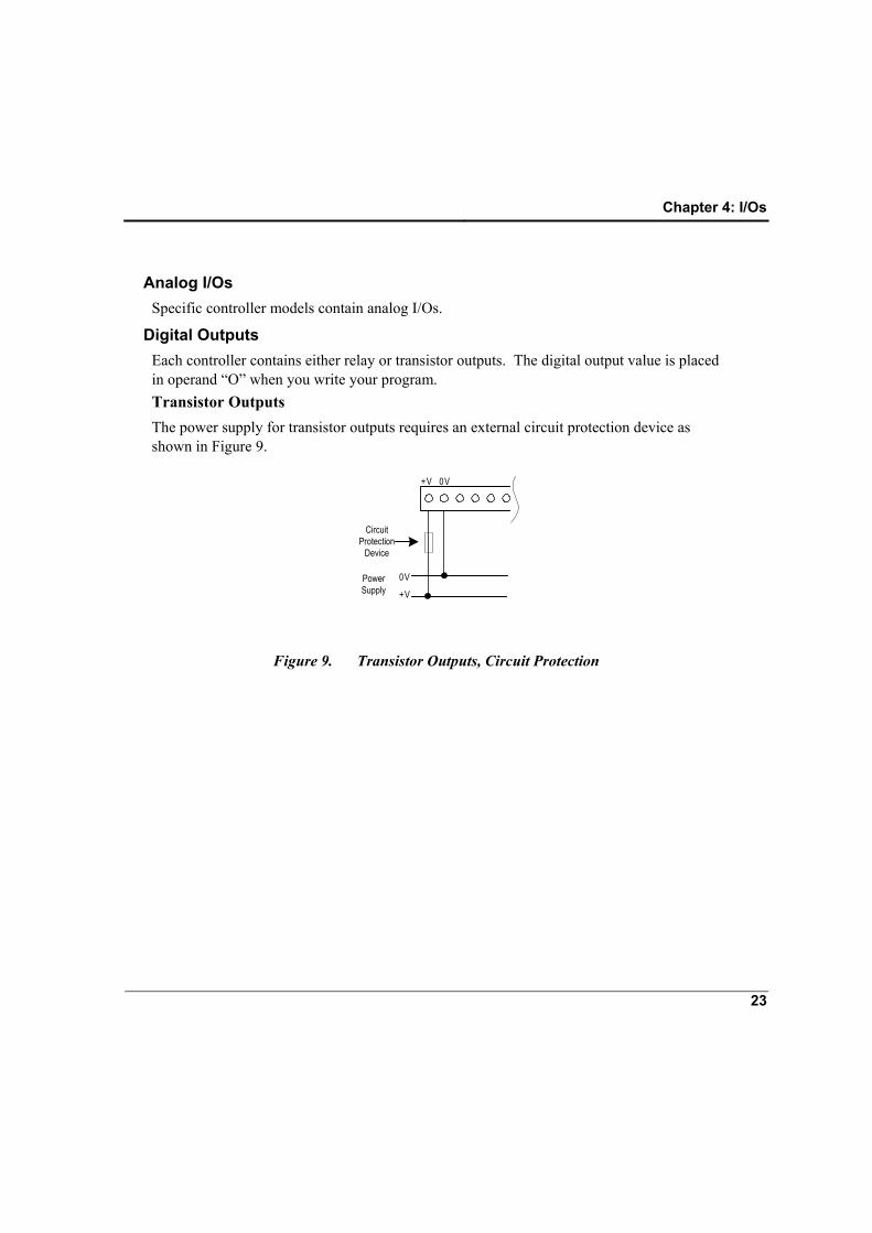
Digital Outputs Each controller contains either relay or transistor outputs. The digital output value is placed in operand “O” when you write your program. Transistor Outputs The power supply for transistor outputs requires an external circuit protection device as shown in Figure 9.
0V
+V
0V+V
CircuitProtection
Device
PowerSupply
Figure 9. Transistor Outputs, Circuit Protection
Jazz™ OPLC™ User Guide
24
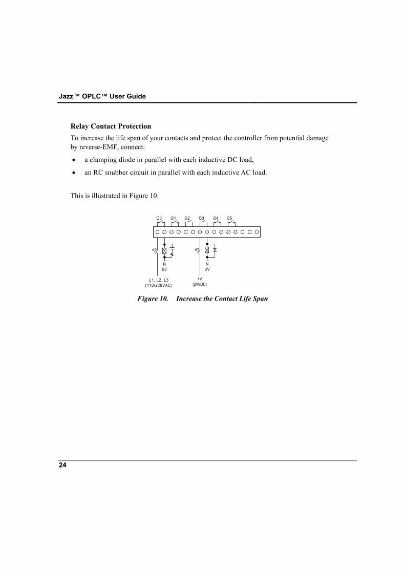
Relay Contact Protection To increase the life span of your contacts and protect the controller from potential damage by reverse-EMF, connect:
• a clamping diode in parallel with each inductive DC load,
• an RC snubber circuit in parallel with each inductive AC load. This is illustrated in Figure 10.
O0 O1 O2 O3 O4 O5
L1, L2, L3(110/220VAC)
N0V
N0V
+V(24VDC)
Figure 10. Increase the Contact Life Span
25
Chapter 5: Customizing the HMI Panel You can customize the operating panel by labeling the keyboard keys. You can label most of the controller’s keys by inserting keyboard slides into slots under the faceplate of the operating panel. Keyboard slides are strips of plastic that are designed and cut to fit under specific groups of keys. To label keys, you write or print text onto a slide; then insert it in the appropriate slot. The text will be visible through the operating panel covering. There is a special slide that allows you to display a picture, such as company logo or a system symbol. Note that slides cannot be inserted under the following keys: the directional arrows, < ↵ > and < i > keys. The controller is shipped with a set of slides is already inserted into the operating panel. Additional sets may be obtained by separate order. Note: Slides must be inserted before the controller is mounted.
Labeling Slides You can label slides using a fine-tip permanent marker, or by using a professional labeling tool to obtain a more professional in appearance.
Jazz™ OPLC™ User Guide
26
Removing and Inserting Your Slides
Caution • Slides fit very tightly into the operating panel slots. This keeps the correct label over the correct key. When you remove or insert slides, work carefully, as excessive force may damage the slide.
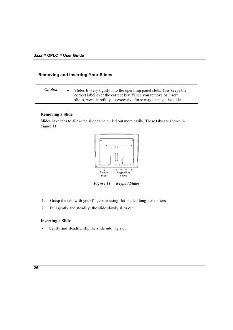
Removing a Slide Slides have tabs to allow the slide to be pulled out more easily. These tabs are shown in Figure 11.
Pictureslide
Keypad keyslides
Figure 11 Keypad Slides
1. Grasp the tab, with your fingers or using flat-bladed long-nose pliers.
2. Pull gently and steadily; the slide slowly slips out. Inserting a Slide
• Gently and steadily, slip the slide into the slot.
27
Chapter 6: Information Mode Information Mode is a utility that is embedded in the operating system of the controller. Via Information Mode, you can view data on the LCD screen and perform certain actions such as resetting the controller. You can enter Information Mode at any time without regard to what is currently displayed on the LCD screen. Viewing data does not affect the controller’s program or whatever task the controller may be performing. Note that executing certain actions in Information Mode, such as initializing the controller, can influence the program. Note that when you use Information Mode, the keyboard is dedicated to that purpose. The keys return to normal application functions when you exit Information Mode.
Using Information Mode 1. To enter Information mode, press the <i> button on the controller’s keyboard down for
several seconds.
2. The controller enters Information Mode.
3. To navigate between categories, use the right/left arrow keys.
4. To enter a category, press the Enter button.
5. Use the directional arrows to move between options, the Enter button to select options, and the keypad to enter data, such as changing the time of the controller’s RTC.
6. To exit Information mode, press the <i> button. Each press returns one level up. Press the number of times necessary to exit.
You can set a password to block users from entering the System category in Information Mode, by writing a power–up value into SI 179, Info Password.
Caution • The controller will block entry into the System Category until the correct password has been entered. This is why you must record any password you set for your controller.
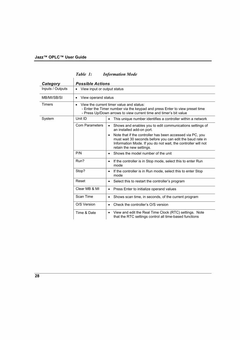
Table 1 shows information that can be accessed in this mode.
Jazz™ OPLC™ User Guide
28
Table 1: Information Mode
Category Possible Actions Inputs / Outputs • View input or output status
MB/MI/SB/SI • View operand status
Timers • View the current timer value and status: - Enter the Timer number via the keypad and press Enter to view preset time - Press Up/Down arrows to view current time and timer’s bit value
System Unit ID • This unique number identifies a controller within a network
Com Parameters • Shows and enables you to edit communications settings of an installed add-on port.
• Note that if the controller has been accessed via PC, you must wait 30 seconds before you can edit the baud rate in Information Mode. If you do not wait, the controller will not retain the new settings.
P/N • Shows the model number of the unit
Run? • If the controller is in Stop mode, select this to enter Run mode
Stop? • If the controller is in Run mode, select this to enter Stop mode
Reset • Select this to restart the controller’s program
Clear MB & MI • Press Enter to initialize operand values
Scan Time • Shows scan time, in seconds, of the current program
O/S Version • Check the controller’s O/S version
Time & Date • View and edit the Real Time Clock (RTC) settings. Note that the RTC settings control all time-based functions

29
Appendix A: New PLC Users PLCs, or Programmable Logic Controllers, are electronic control systems based on microprocessors. A PLC performs control functions in accordance with its software program of external automated equipment.
Parts of a PLC Operating Panel The operating panel provides what is called the HMI, or Human Machine Interface, between you and the PLC. The panel is composed of an LCD screen and a customizable keypad. The LCD screen displays messages to the operator. You assign functions to the keys when you write your software program. Inputs Inputs receive signals from external devices such as switches, push buttons and variable voltage signals from analog devices. The inputs convert the voltage to signals that the PLC can process. Outputs Outputs send signals from the PLC to external devices such as lights or contactor coils. Outputs convert the PLC program results into signals that these external devices can process. CPU The Central Processing Unit is the brain of the PLC. It executes the control program.
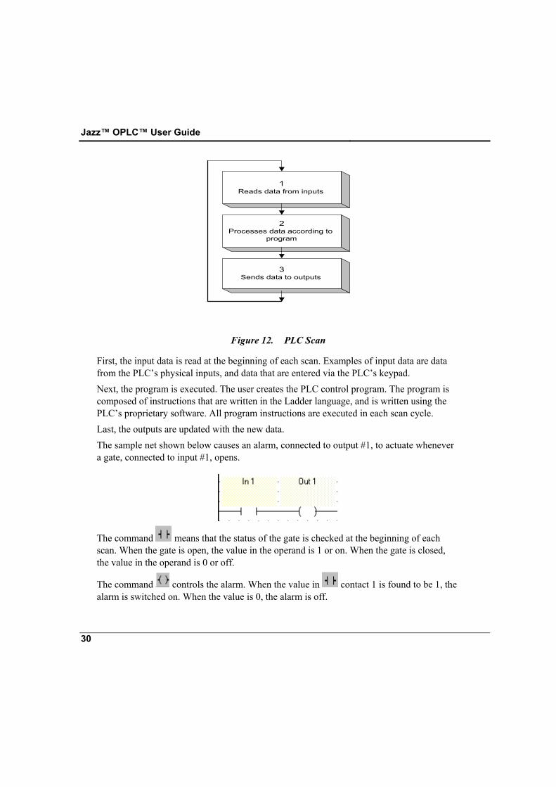
How PLCs Work The figure below shows the PLC cycle. This cycle is called a scan. The scan cycle is performed continuously.
Jazz™ OPLC™ User Guide
30
1Reads data from inputs
2Processes data according to
program
3Sends data to outputs
Figure 12. PLC Scan
First, the input data is read at the beginning of each scan. Examples of input data are data from the PLC’s physical inputs, and data that are entered via the PLC’s keypad. Next, the program is executed. The user creates the PLC control program. The program is composed of instructions that are written in the Ladder language, and is written using the PLC’s proprietary software. All program instructions are executed in each scan cycle. Last, the outputs are updated with the new data. The sample net shown below causes an alarm, connected to output #1, to actuate whenever a gate, connected to input #1, opens.
The command means that the status of the gate is checked at the beginning of each scan. When the gate is open, the value in the operand is 1 or on. When the gate is closed, the value in the operand is 0 or off.
The command controls the alarm. When the value in contact 1 is found to be 1, the alarm is switched on. When the value is 0, the alarm is off.
31
Table of Figures Figure 1. The Jazz™ OPLC .......................................................................... 11 Figure 2. Jazz™ OPLC™, Connectors, Brackets, and Gasket...................... 15 Figure 3. Inserting an Add-on Module into the Jazz™ Jack......................... 16 Figure 4. Add-on Module Space Requirements ............................................ 16 Figure 5. Panel-Mounting.............................................................................. 18 Figure 6. DIN-Rail Mounting........................................................................ 18 Figure 7. DIN-Rail Removal ......................................................................... 18 Figure 8. Power Supply Wiring..................................................................... 20 Figure 9. Transistor Outputs, Circuit Protection ........................................... 23 Figure 10. Increase the Contact Life Span ...................................................... 24 Figure 11 Keypad Slides ................................................................................ 26 Figure 12. PLC Scan........................................................................................ 30

Jazz™ OPLC™ User Guide
32
Notes