vista imaging installation guide section 2.7.1.1 procedure for sites interfacing vista imaging with...
TRANSCRIPT

VistA Imaging Installation Guide January 2017 - Revision 29
MAG*3.0*130, 133, 131, 135, 140, 167
Department of Veterans Affairs Product Development
Health Provider Systems

VistA Imaging System MAG*3.0*130, January 2017 MAG*3.0*131, MAG*3.0*133, MAG*3.0*135, MAG*3.0*140, MAG*3.0*167 ii Installation Guide--Rev. 29
Preface This guide is written to assist IRM personnel to install the VistA Imaging System V. 3.0 application. IRM personnel should have knowledge of workstations, Windows server and workstation software, and network component installation. This guide is intended to supplement (but not replace) installation manuals provided by the vendor of Imaging System components.
**Copyright Notice: Portions of the imaging technology of VistA Imaging System are
copyrighted by AccuSoft Corporation.
Revision History
5 Nov 2003 Updated manual with information pertaining to Patches 22 and 24 (rev 1).
6 Apr 2004 p3 updates for sections 2.4.5, 2.4.5.1 and 2.7.1.1. Sections 2.4.5.2 and 2.4.5.4 declared obsolete and have been deleted. Cleanup of Appendix C (no content changes). (rev 2.
6 May 2004 p32 updates for Chapter 3 (replacement chapter). (rev 3)
04 Aug 2004 p33 updates to sections 2.5.4 – 2.5.6.3, 2.7.2, and 4.1 – 4.1.2.10. (rev 4) Updated section 1.1.1 and 2.4.2 to remove old hardware information. Updated sections 2.2 – 2.2.4 to reflect use of Windows 2000 on file servers. Deleted obsolete sections 2.4.2.1 and 2.4.2.2 and all subsections in A.1.3. Removed outdated Windows NT and G3 compression references throughout.
30 Sept 2004 P8 updates (rev 5): - Section 2.5.1 Overview of Installation of Imaging Workstation Software - Sections 2.5.5 – 2.5.5.6 Setting Up and Using Autoupdate - Sections 2.5.6 – 2.5.6.3 Edit the Imaging Workstation Configuration File with the
MAGSYS Tool - Sections 2.5.8. – 2.5.8.9 Testing Imaging System Function - Section 2.7.1.1 Procedure for Sites Interfacing VistA Imaging with the MUSE
System - Section 2.7.1.2 Setting Up the Clinical Capture Workstation to Allow Means Tests
Scanning Configuration - Section 4.1.1.3 Capture Workstation Configuration for Matrox - Section 4.3.1 Configuring a TWAIN Device - Section 6.1.2.5 VistA Imaging Capture, Test Mode
18 Feb 2005 Corrections to Sept 30, 2004 – P8 documentation updates. (rev 6)
9 Mar 2005 P48 updates (rev 7): - Section 2.5.6.3 Workstation Configuration File (MAG308.INI) Setting - Section 2.7.3.3 Configuring the capture workstation for means test scanning

28 Mar 2005 Additional updates (rev 8): - Section 2.5.6.3 Workstation Configuration File (MAG308.INI) Setting - Section 2.7.3.3 Configuring the capture workstation for means test scanning.
05 Dec 2005 Patch 57 updates (rev 9): A. McFarren, C. Huesman. - Revised outdated content in the following sections: 1.1.1, 1.2.1, 1.2.5, 1.3.3, 2.0,
2.2.1, 2.4.2, 2.4.6, 2.5.1, 2.5.3, 2.5.5.2, 2.5.5.4, 2.6, 2.7.1.1, 3.2.1 - Added information about Diagram Annotation tool to section 2.7.4 - Revised and expanded information in Appendix C - Incorporated p45 changes to the following sections: 2.2.4, 2.5.4.2, 2.5.6.1-3.
27 Jun 2006 Patch 51 and 18 updates (rev 10): A. McFarren, J. Christensen. - Updated section 3.2.3 to reflect p51 changes. - Updated all of Chapter 3 to reflect p18 changes.
18 Jul 2006 Patch 20 updates (rev 11): S. Davis, A. McFarren, R. Coney - Updated sections 2.4.1-2.4.5.2, 2.6.1, 2.7 – 2.7.3.4, and 6.1.4.1 to reflect p20
changes.
04 May 2007 Updates for Patch 46 and Patch 65 (rev 12): A. McFarren, C. Huesman. - Added revision number to title page, footer, and revision table. - Added new TeleReader sections (2.5.4 and 2.7.2) for Patch 46. Updated sections
1.1.1, 1.2.1, 2.5.5, and 2.7.2 for Patch 46. - Updated sections 3.2.3, 3.2.3.1, 3.2.4—3.2.4.4, 3.3.2, 3.3.3, 3.3.3.1, and 3.3.3.3.2 for
Patch 65.
14 Jan 2008 Updates for Patch 76 and general corrections (rev 13): A. McFarren, S. Davis, C. Huesman. - Removed obsolete OS information from sections 2.5.1, 2.5.2, and 2.5.6.2. Applied
p81-related changes previously missed to sections 2.4.3 and 2.4.4 - Added new sections Voxar integration sections (3.2.4.5, 3.2.4.5.1 and 3.2.4.5.2),
updated sections 3.2.1, 3.2.1.1, 3.2.2.5, 3.2.3, 3.2.3.2, 3.2.4.3 and 3.3.2.1
29 Feb 2008 Patch 59 (rev 14): S. Davis, C. Huesman. - Updated section 6.1.4.2 to reflect p59 changes.
Aug 19 2008 Patch 95 (rev 15) updates and general maintenance; A. McFarren, D. Carozza. - Updated and reformatted list of patches in section 1.2.1 - Updated and expanded sections 2.7.1.1 and 2.7.2 for Patch 95. - Fixed outdated Demo Mode content (updates to section 2.5.7.3, deleted obsolete
Demo Mode section (6.1.2.4), feature no longer present).
10 Feb 2010 Patch 93 and Patch 101 (rev 16) updates and general maintenance, D. White, J. Kennedy - Updated sections 1.2.5, 2.3.4, 6.1.5, 6.1.6, 6.1.2.3 for Patch 93 - Updated Section 3 for Patch 101
05 Oct 2010 Patches 90, 94, and 114 (rev 17). C. Gilbert, M. Kaji, D. White, J. Kennedy - Updated section 3 for Patch 90 - Updated section 6.1.2.2 for Patch 94 - Added new sections 2.7.6 and 2.7.6.1 for Patch 114
01 Feb 2011 Patches 105 and 98 (rev 18). R. Coney, C. Gilbert, H. Suri, D.White - Updated sections 2.3.1, 2.3.3, and added 2.3.3.1 for Patch 98 - Updated section 1.1.1 and added 2.7.6, 2.7.6.1-4 for Patch 105 - Non-patch updated section “Securing IIS. OCIS is now IPRM.

21 Mar 2011 Patch 115 (rev 19). M. Kaji, M. Turian, J. Kennedy - Updated section 3 for Patch 115
04 May 2011 Patch 106 (rev 20). C. Gilbert, D. White - Updated sections 1.1.1, 2.5.7.2, 2.5.7.3, 2.5.9, 2.7.3.2, and added new section
2.5.9.10
31 May 2011 Patch 39 (rev 21). C. Gilbert, D. White - Updated sections 2.3.4, 2.4.2, 2.4.4, 2.4.5.1, 2.4.5.2, 2.6, 2.7.1, 2.7.3, 3.3.2.6,
3.3.3.2.6, and 6.1.4 - Added new sections 2.4.7 and 2.7.3.1 - Made global text corrections listed on pages 1 and 2 of the Change Pages document
01 Sept 2011 Patch 117 (rev 22). M. Kaji, H. Suri, L. Scorza - Revised sections 1.1.1, 2.3.4, 2.5.1, 2.5.2, 2.5.3 – 2.5.5, 2.5.5.2, 6.1.5. - Removed section 2.5.8.
09 Nov 2011 Patch 104 (rev 23). R. Coney, A. Sunbear. - Revised section 1.1.1.
26 Nov 2012 Patch 122 (rev 24). C. Gilbert, K. Bahr, L. Scorza - Revised sections 1.1.1, 2.3.4, and 2.6.6.1. - Added new section: Appendix D: Setting Parameter Values.
15 Mar 2013 Patch 124 (rev 25) P Yeager, H. Suri, C. Huth - Revised sections 1.1.1 , 2.6.7, 2.6.7.1, and 2.6.7.4 - Added new terms to Index
01 August 2013 Patch 34/116/118, 119, 127, 129 (rev 26) P. Yeager, C. Gilbert, C. Huth - Revised sections 2.5.1, 2.5.5, 2.5.5.1, 2.5.5.2, 2.5.5.3, 2.5.5.4, 2.5.6, 2.5.7, 2.5.7.2,
2.6.2.1, 2.7.6.1, - Deleted sections 2.3.3.1, 2.6.2.2 - Added section 2.6.2.3 - Updated Index
16 September 2012 (rev 27) Revised with updates for Patch 135 throughout; new section 2.8 for Patch 130 and 140; revisions to sections 2.5.5.1, 2.5.5.6, and new section - 2.7.3 for Patch 131. Revised sections 3.2.1, 3, .2.2., 3.2.3, 3.2.4; deleted section 3.2.7, for Patch 133.Updated Index. J. Christensen, C. Gilbert, L Scorza, C. Huth
18 January 2017 In support of MAG*3.0*167, edited Section 2.6.1.1 and removed table in Section 2.6.1.2, as these options are no longer available. Also, added text to 2.6.1 (on MUSE settings) and 2.6.1.2 (error codes).
Garrett Kirin, Stacey Marner

Table of Contents Chapter 1 Introduction ................................................................................................................1 1.1 The VistA Imaging System .....................................................................................................1
1.1.1 VistA Imaging System Components ........................................................................1 1.1.2 Workstation Placement ............................................................................................4 1.1.3 System Utilization Studies .......................................................................................4 1.1.4 Summary ..................................................................................................................5
1.2 Site Requirements for Use of the VistA Imaging System ......................................................5 1.2.1 Package Requirements .............................................................................................5 1.2.2 User Access to Workstations ...................................................................................5 1.2.3 Staffing Requirements .............................................................................................6 1.2.4 Contractors’ Services ...............................................................................................6 1.2.5 Imaging System Approved Components .................................................................6 1.2.6 Reporting Problems .................................................................................................7
1.3 Imaging System Evolution ......................................................................................................7 1.3.1 Introduction ..............................................................................................................7 1.3.2 Network Topology Requirements ............................................................................8 1.3.3 Tier 1 and Tier 2 File Servers Requirements ...........................................................8 1.3.4 Future Plans for the VistA Imaging System ............................................................8
Chapter 2 VistA Imaging Core Infrastructure Installation ...................................................11 2.1 Assumptions ..........................................................................................................................11 2.2 Imaging File Server Setup ....................................................................................................11
2.2.1 Configuration and Naming Conventions ...............................................................11 2.2.2 Creating Imaging Accounts ...................................................................................12 2.2.3 Verifying Folder and Share Permissions ...............................................................13 2.2.4 Maintaining File Server Security ...........................................................................13
2.3 VistA Hospital Information System Management Software Setup ......................................14 2.3.1 VistA RPC Broker Installation ..............................................................................14 2.3.2 Loading Imaging Package - KIDS Installation ......................................................15 2.3.3 Device Setup ..........................................................................................................19 2.3.4 Assign Imaging Menu Option and Security Keys .................................................19
2.4 Background Processor Installation .......................................................................................20 2.4.1 Introduction ............................................................................................................20 2.4.2 Requirements & Functions ....................................................................................20 2.4.3 Distribution ............................................................................................................21 2.4.4 Installation Instructions ..........................................................................................21 2.4.5 Imaging M File Setup ............................................................................................25 2.4.6 Tier 2 Software Installation ...................................................................................29 2.4.7 Monitoring BP Servers ..........................................................................................31
2.5 Imaging Workstation Setup ..................................................................................................33 2.5.1 Overview of Installation of Imaging Workstation Software..................................33 2.5.2 Install the Latest Windows Operating System Approved by the VA ....................34 2.5.3 Install RPC Broker Client Software .......................................................................34

2.5.4 Install Sentillion Vergence Desktop Components .................................................34 2.5.5 Install the VistA Imaging Workstation Software ...................................................35 2.5.6 Setting Up and Using Autoupdate .........................................................................41 2.5.7 Edit the Imaging Workstation Configuration File with the MAGSYS Tool .........42 2.5.8 Testing Imaging System Function .........................................................................52
2.6 Installing Optional Components ...........................................................................................57 2.6.1 MUSE EKG Interface ............................................................................................57 2.6.2 Associating Display and Capture with CPRS ........................................................59 2.6.3 Configuring VistA Imaging to Process a GCC ......................................................65 2.6.4 Diagram Annotation Tool Interface .......................................................................66 2.6.5 TeleReader Interface ..............................................................................................67 2.6.6 TeleReader Configurator Interface ........................................................................67 2.6.7 VistA Imaging AWIV ............................................................................................68
2.7 Reverting to the MAG*3.0*122 Version of the Clinical Clients..........................................70 2.7.1 Reverting to the MAG*3.0*122 TeleReader Client ..............................................71 2.7.2 Reverting to the MAG*3.0*122 Clinical Display Client.......................................71
2.8 Reverting to a Previous Version of Client Software that is NOT MAG*3.0*122 ...............71
Chapter 3 VistARad Installation ...............................................................................................72 3.1 Introduction ...........................................................................................................................72 3.2 VistARad Workstation Setup ................................................................................................72
3.2.1 Workstation Preparation ........................................................................................72 3.2.2 Configuration for High-Resolution Monitors ........................................................74 3.2.3 Software Installation for Diagnostic Workstations ................................................80 3.2.4 VistARad Client Software Setup ...........................................................................83 3.2.5 Optional Interface Configuration ...........................................................................87 3.2.6 Maintenance of High-Resolution Monitors ...........................................................91
3.3 VistA Server Setup for VistARad .........................................................................................92 3.3.1 VistA Hospital Information System (Host) Requirements ....................................92 3.3.2 Basic Configuration ...............................................................................................92 3.3.3 Detailed Configuration...........................................................................................99
3.4 Testing a VistARad Installation ..........................................................................................114 3.4.1 Requirements for Testing .....................................................................................114 3.4.2 Performing Testing ..............................................................................................115
3.5 Running VistARad in Training Mode.................................................................................115
Chapter 4 Installing Image Acquisition Devices ....................................................................119 4.1 Video Inputs ........................................................................................................................119
4.1.1 Video Capture Board Installation and Setup .......................................................120 4.1.2 Setup Notes for Specific Instruments ..................................................................124
4.2 Still Digital Cameras ...........................................................................................................128 4.3 TWAIN Devices .................................................................................................................129
4.3.1 Configuring a TWAIN Device.............................................................................129 4.3.2 Scanned Documents .............................................................................................129 4.3.3 Color Page and Transparency Scanners ...............................................................129
4.4 Laser X-ray Film Digitizers ................................................................................................130 4.4.1 Configure Hardware and Install Drivers and Software ........................................130 4.4.2 Testing Scanner Software ....................................................................................130

Chapter 5 Workstation Furniture and Physical Security .....................................................131 5.1 Stationary Display Workstations ........................................................................................131 5.2 Mobile Display Workstation ...............................................................................................131 5.3 Electrical Power Isolation Transformers ............................................................................131 5.4 Securing Workstations ........................................................................................................131
Chapter 6 Troubleshooting ......................................................................................................133 6.1 Troubleshooting ..................................................................................................................133
6.1.1 Cannot Connect to the VistA Server ....................................................................133 6.1.2 Cannot Display or Capture Images ......................................................................134 6.1.3 Slowness when Displaying or Capturing Images ................................................137 6.1.4 Other Helpful Hints..............................................................................................137 6.1.5 QA Review Utility ...............................................................................................138 6.1.6 QA Image Edit Utility ..........................................................................................139
Appendix A Security .................................................................................................................141 A.1 Workstation Security.............................................................................................................141
A.1.1 BIOS Changes ........................................................................................................141 A.1.2 Virus Protection .....................................................................................................141 A.1.3 Windows System Policies and Profiles ..................................................................141 A.1.4 Imaging Software ...................................................................................................141 A.1.5 Physical Protection .................................................................................................141 A.1.6 Medical Center Policy ............................................................................................142
A.2 Windows Server Security......................................................................................................142 A.2.1 Folder and Share Security ......................................................................................142 A.2.2 Hidden Shares ........................................................................................................142
Appendix B Backups.................................................................................................................143
Appendix C Using MediaStor and DiskXtender ....................................................................145 C.1 Adding Media to Tier 2 .........................................................................................................145
C.1.1 Inserting Media ......................................................................................................145 C.1.2 Adding Media to the Application Pool ..................................................................146
C.2 Setting up New Media for Image Storage .............................................................................148 C.2.1 Labeling & Assigning Media .................................................................................148 C.2.2 Adding Media to the Move Group .........................................................................151
C.3 Using Media Copy for Backups ............................................................................................152 C.3.1 Making a Media Copy ............................................................................................152 C.3.2 Removing Original Media ......................................................................................155 C.3.3 Promoting Copy Media ..........................................................................................156
C.4 Using Platter Compaction to Migrate to High-capacity Media.............................................158 C.4.1 Performing Platter Compactions ............................................................................158
C.5 Configure Server Schedules ..................................................................................................160 C.6 Configure Server Alerts ........................................................................................................161
Appendix D Setting Parameter Values ...................................................................................163 Annotation Parameters Example ..................................................................................................163

Index ..................................................................................................................................165
VistA Imaging System MAG*3.0*130, January 2017 MAG*3.0*131, MAG*3.0*133, MAG*3.0*135, MAG*3.0*140, MAG*3.0*167 1 Installation Guide--Rev. 29
Chapter 1 Introduction 1.1 The VistA Imaging System The VistA Imaging System is an extension of the Veterans Health Information System Technology Architecture (VistA) hospital information system that captures a wide range of clinical images, scanned documents, and other non-textual data files and makes them part of the patient’s electronic health record.
The VistA Imaging System is unique in that management of the medical images is an integral part of a hospital information system. Image and text data are provided in an integrated manner that facilitates the clinician’s task of correlating that data and making patient care decisions in a timely and accurate way.
The system is designed to provide the treating physician with a complete view of patient data, and at the same time allow consulting physicians to have access to that image and text data. It serves as a tool to aid communication and consultation among physicians -- whether in the same department, in different medical services, or at different sites.
1.1.1 VistA Imaging System Components The VistA Imaging System is composed of a variety of components, including:
• VistA Imaging software on the VistA Hospital Information System. • Clinical Imaging workstations for image display and image capture. • Diagnostic (VistARad) workstations for dedicated high-resolution image display. • One or more DICOM Gateways interfaced to DICOM-compliant image sources. • Background Processor server(s), used to manage image storage and transfer on Tier 1 and Tier 2
servers. • The VistA Imaging Exchange (VIX) service to support remote image views and VA-DoD
image sharing. • The Advanced Web Image Viewer (AWIV), which adds image display capabilities to
VistAWeb. • The Advanced Web Image Viewer Web Application, which is hosted on the CVIX and
enables use of the AWIV via Microsoft Internet Explorer, independently of VistAWeb. • A network which integrates all these components with the VistA Hospital Information System. Each component is described below. For information about hardware requirements, refer to documents posted at http://vaww.va.gov/imaging/IMGplanproc.htm or contact the VistA Imaging development group.
VistA Imaging Software on VistA System: The VistA Imaging System uses FileMan files and software located on the VistA servers. These files hold image information in M globals, including…
• Control information for Imaging client software • Multimedia data type information

Chapter 1 – Introduction
• Image locations • Image attributes This information is used by other VistA Imaging components to access image files and control image display.
Clinical Imaging Workstations: Workstations running the Clinical Display and/or Clinical Capture software can be located throughout the hospital. These Windows-based applications allow…
• Acquisition of images • Display of the complete multimedia online patient record, including optional access to ECG
tracings stored on a Marquette MUSE EKG Management system.
Clinical Imaging workstations typically run CPRS. In addition to being integrated with CPRS, the Clinical Display and Capture software can display information from the following VistA packages:
• Clinical Procedures (and Medicine) • Surgery • Laboratory • Radiology • Text Integration Utility (TIU), supporting Progress Notes and Consults Clinical Imaging workstations can be interfaced with image producing devices. The resulting images are incorporated into the patient’s online record using the Clinical Capture software. Examples of devices that can be interfaced include…
• Digital cameras • Document scanners • Endoscopes • Ultrasound scanners • Video cameras which can be connected to microscopes or ophthalmoscopes • X-ray scanners The list of devices that can be interfaced is constantly expanding. For detailed information, refer to the Clinical Capture Devices for VistA Imaging document, posted at http://vaww.va.gov/imaging/IMGplanproc.htm.
Clinical Imaging workstations, whether based on PC or thin client hardware, must meet certain minimum display quality standards. These requirements are dependent on the type of images being displayed. The Clinical Display and Capture software checks display quality on startup and will prevent image display if monitor resolution/bit depth is not sufficient. For details, see the System Requirements for the Use of Thin Client Technology with VistA Imaging posted at http://vaww.va.gov/imaging/ThinClientDirective.pdf.
Sites can configure whether or not TeleReader will be able to access and read images on a workstation that accesses VistA Imaging through a Thin Client.
Clinical Display has the ability to display images from remote sites that a patient has seen at. For more information, see the Clinical Display User Manual.
Chapter 1 – Introduction
Diagnostic (VistARad) Workstations: A high end workstation running VistARad software is suitable for primary diagnostic interpretation of radiology exams produced by CR, CT, MRI, and other modalities. VistARad workstations can be located in the Radiology department or wherever primary diagnostic interpretation is required.
VistARad is integrated with the Radiology package, and bases its exam lists on Status Code definitions stored in the Radiology package’s Examination Status file (#72).
A VistARad workstation must be a dedicated workstation—only the VistARad software and a few approved supporting programs can be installed. VistARad workstations must incorporate high-resolution display adapters and 1, 2, or 4 high-resolution grayscale monitors. It should have sufficient processor speed and memory to display large exams with a minimum of delay.
VistA Imaging Advanced Web Image Viewer (AWIV): The AWIV adds image display capabilities to VistAWeb in much the same way that the Clinical Display application adds image display capabilities to CPRS. The AWIV is a Web-based application that provides a subset of the features of Clinical Display. When the AWIV is installed, images associated with progress notes or radiology reports can be accessed from within the VistAWeb application. The AWIV can be launched only from VistAWeb (version 13 or later) in a VA-approved version of Microsoft Internet Explorer. The AWIV retrieves information and images from across the VA WAN. This may affect the performance of the AWIV in displaying images.
The AWIV can be accessed from within the VistAWeb application and through the AWIV Web Application, which is hosted on the Centralized VistA Image Exchange (CVIX). AWIV installation information is covered briefly in this manual. For information about using the AWIV, see the VistA Imaging AWIV User Guide and the VistA Imaging AWIV Web Application Guide. DICOM Gateways: DICOM Image and Text Gateways are used to transfer images and data from DICOM-compliant acquisition modalities to the VistA Imaging system. Once images are stored on VistA Imaging servers, they can be displayed on the Clinical Imaging and VistARad workstations.
DICOM Gateways are covered in detail in the DICOM Gateway Installation Guide.
Background Processor Server and Imaging Servers: At least one Background Processor Server must be present to perform utility functions such as copying image files to and from Imaging Tier 1 and Tier 2. Imaging Tier 1 Servers are used to store the most recently acquired and accessed image files.VIX (VistA Image Exchange) service: The VIX is typically installed on the Imaging server cluster. The VIX provides enhanced VA-VA remote image viewing, and along with the CVIX (the Centralized VIX) enables VA-DoD image sharing. For additional information, refer to the VIX Administrator’s Guide. Local Area Imaging Network: The VistA Imaging System uses a local area network (LAN) to connect VistA Imaging workstations to image file servers and to the main VistA Hospital Information System. The local area network uses Fast (100 mb/s) Ethernet or Gigabit Ethernet technology (Gigabit Ethernet is strongly recommended for sites running VistARad).

Chapter 1 – Introduction
1.1.2 Workstation Placement Clinical Workstations are typically located in a number of departments and patient care areas. Each site must decide where to locate their workstations based on the services that will be using them. The CPRS application will generally be run on the VistA Imaging workstations.
Image input workstation locations may include the…
• Cardiology department • Gastroenterology endoscopy lab • Bronchoscopy examination room • Surgical pathology reading room • Hematology laboratory • Dermatology and rheumatology clinics • Operating room • Radiology and nuclear medicine department
Image display workstations should be placed in conference areas, including…
• The auditorium • Service conference rooms • Ward conference areas
… As well as patient treatment areas on…
• Wards • Clinics • Emergency room • Intensive care units A larger monitor or projector should be used in conference areas. Special color image printers can be located in the medical media department, or another convenient location. Ordinary printers can be used to print images and reports from VistA Imaging.
A medical center may want to incrementally build their imaging system, serving a subset of medical services in the beginning and increasing the number of workstations gradually. There are clusters of services that see the same patients and need to share images to provide treatment. They often hold joint conferences weekly. Workstations will be best utilized if they address the needs of such clusters. Generally, all services need access to radiology images.
1.1.3 System Utilization Studies In order to monitor workstation usage to meet regulatory requirements and for licensing purposes, the VistA Imaging Project is logging a number of workstation statistics. This information also provides valuable feedback to the system developers and Information Resources Management (IRM) support staff. It may help determine the need for additional user training in particular areas or to assist in decisions related to the location of VistA Imaging workstations.

Chapter 1 – Introduction
1.1.4 Summary The VistA Imaging System has been received very well by its users, and serves as an incentive for clinicians to use the automated patient record system. The VistA Imaging System is meeting real needs for integrated image and text data that cannot be met in other ways.
1.2 Site Requirements for Use of the VistA Imaging System
1.2.1 Package Requirements The VistA Imaging System is designed to be used with the following VistA packages. Required packages:
• Kernel V. 8.0 • VA FileMan V. 22 • RPC Broker 1.1
Additional packages that may be needed, depending on a site’s implementation requirements):
• Consult/Request Tracking V. 3.0-required for capturing images to the Consult/Request Tracking package.
• Medicine V. 2.3– required for capturing images to the Medicine package. • Laboratory V. 5.2 – required for capturing images to the Laboratory package. • Radiology/Nuclear Medicine V. 5.0 – required for capturing images to the Radiology
package. • Surgery V. 3.0 – required for capturing images to the Surgery package. • TIU V. 1.0 – required for capturing images to the Text Integration Utility package. • PIMS V 5.3 - required for displaying Patient Profile report and patient security lookup. • Health Summary 2.7 – required for displaying Health Summary report.
The software developers for the following patches have developed callable routines to support GUI applications such as the VistA Imaging System. Please ensure that the following patches are installed for the packages with which VistA Imaging will be used. During the install process a warning will be displayed for each of the patches that are missing. Patches are available via the National Patch Module on FORUM.
DG*5.3*124 DG*5.3*249 DG*5.3*265 DG*5.3*276 DG*5.3*277 GMRC*3.0.51
LR*5.2*121 MC*2.3*30 TIU*1.0*1 TIU*1.0*47 TIU*1.0*63 TIU*1.0*223
RA*5.0*23 RA*5.0*56 SR*3.0*66 XWB*1.1*28 XWB*1.1*41 XWB*1.1*34
1.2.2 User Access to Workstations Access to the workstations must be restricted in order to prevent…
• Modifications to the workstation setup, files, and directory structures • Filling of the disk with extraneous software and internet files

Chapter 1 – Introduction
Methods are described in Appendix A of this document and in the VistA Imaging System Security Guide.
1.2.3 Staffing Requirements VA staffing guidelines recommend that a network of 50 workstations should have one FTEE to manage the workstations; a full time network manager may also be needed. An imaging network is similar. We have found that at least one FTEE is needed for a 50-workstation imaging network. A site with fewer workstations and servers may be able to reduce this to a minimum of one half FTEE. The VistA Imaging System manager will need to be familiar with PC hardware, software, setup, and troubleshooting. This individual should also be familiar with Windows and M. There is training available commercially, and within the VA, in these areas.
It is very important to have clinical ADP (Automatic Data Processing) support staff to assist users in interfacing imaging devices and other systems to the VistA Imaging workstations and network. They will need to provide training to clinicians using the system, especially during the first year of operation. At smaller imaging system installations, a single individual with appropriate background could both support the network and serve as the clinical ADP support person.
1.2.4 Contractors’ Services It is essential that sites provide maintenance on imaging components. Maintenance contracts provide this service with the minimum of VA staff time. VA staff will still need to be familiar with common problems. However, once the problem is identified, its resolution should become the contractor’s responsibility.
It is important to have a “hot spare” workstation available at all times. VistA Imaging workstations are used during medical procedures and clinical conferences. If a workstation is not available, this will interfere with the delivery of clinical care. This requires that IRM be ready to attend to trouble calls from imaging users immediately.
It is recommended that sites contract for installation of VistA Imaging System core components, including Windows-based file servers, Tier 2 and associated storage management software. The network operating system should be installed before delivery. It is also possible to purchase expertise in network installation, configuration, and maintenance. If this is done, be sure to require network documentation from the contractor.
1.2.5 Imaging System Approved Components The VistA Imaging System consists of a group of off-the-shelf components that are integrated to create a unique system. Some of these components are on the cutting edge of technology. For some components, there are many variations available in the market place. However, each variation has subtle differences that may not be known to their vendors.
The VistA Imaging System is regulated by the FDA as a medical device. This means that all hardware used with VistA Imaging must be tested by the VistA Imaging Project Team. It also means that no modifications can be made in the field to VistA Imaging software.
Therefore, the VistA Imaging staff has carefully tested equipment and software that is recommended to be sure they meet specified requirements, and to determine a configuration to
Chapter 1 – Introduction
best allow integration with other components. VistA Imaging staff maintains a list of tested and supported equipment, and require that sites use equipment from this list to receive VA support.
Note: All equipment for use with the VistA Imaging System must meet specifications defined by the VistA Imaging staff. For more information refer to documents posted at http://vaww.va.gov/imaging/IMGplanproc.htm or contact the VistA Imaging HSD&D group. Users may ask to run other software on Clinical Imaging Workstations. VistARad workstations have special restrictions, which are covered in Chapter 3 of this document. For support and security reasons, we recommend some limitations on user access to the workstation. In any case, a site may choose to restrict its users from running other software, such as word processing, if this is felt not to be a cost-effective use of the imaging equipment. Note: Additional software (such as word processors) is NOT to be installed on diagnostic workstations running VistARad. Only software expressly approved by the VistA Imaging Group team may be installed on diagnostic workstations running VistARad.
1.2.6 Reporting Problems The VistA Imaging System is a complex system. If you encounter problems that cannot be handled at the site, please document them in a Remedy call and contact the National VistA Support desk. You will be referred to the VistA Imaging support team.
1.3 Imaging System Evolution
1.3.1 Introduction A hospital imaging system can be implemented at one time or incrementally over a period of time. Even if equipment is purchased and installed at one time, it is best to gradually add users and service functionality to the system. It takes time for the IRM staff to be trained and gain experience in how to support imaging technology. Also, it takes time for the initial users of the system to become comfortable enough with the applications to use them during procedures and conferences. Devices within services will need to be connected to workstations. Clinical advocates, or ADPACs (Automatic Data Processing Application Coordinator), are very helpful in bringing together clinical image users and IRM staff to implement the capture of new image types. This is exciting and rewarding but does require effort on the part of IRM.
Begin by identifying an initial group of interested users who will share images. There are clusters of services that see the same patients and need to share images to provide treatment. For example, the GI (gastrointestinal) endoscopy lab may examine a patient and perform a biopsy. The specimen is then sent to the laboratory service. The pathology report may indicate that surgery is necessary. Typically, these three services hold a weekly conference where they plan treatment for patients. Another group is those services participating in Tumor Board Conferences. Radiology images are used by everyone. EKGs are also of wide interest. Workstations will be best utilized if they address the needs of such clusters. Select such a cluster as the starting point.
The G.I., surgical pathology, surgery and radiology services are excellent candidates for initial users of the VistA Imaging System. Workstations would be placed in the following areas:
• G.I. endoscopy suite
Chapter 1 – Introduction
• Surgical pathology office • Conference rooms • Operating room suite
VistA Imaging workstations should be installed where they will be most beneficial. It is useful to differentiate between those workstations that are used to capture images and those workstations that are used predominately to display images. Image capture workstations are placed near the source of the images, while image display workstations should be located in common areas (e.g., conference rooms, ICUs, shared ward offices, etc.). In addition, VistA Imaging software can be loaded on workstations in clinicians’ offices.
As imaging systems grow, they require…
• Expanded network capacity • Additional image file server space • A bigger Tier 2 • Additional IRM management
1.3.2 Network Topology Requirements Contact the VHA Architecture Planning Workgroup (APW) when planning network infrastructure for your site. The network subgroup can be reached by sending a mail message to the VHA CIO APW Network sub-group mail group on Exchange. Be sure to send a copy of any draft plans to the VistA Imaging team for review.
1.3.3 Tier 1 and Tier 2 File Servers Requirements When estimating Tier 1 andTier 2 requirements, it is important to consider image file size and image acquisition rates. Sites should contact their VistA Implementation Manager for preparation of a VistA Imaging System proposal. Further information to assist you in selecting appropriate hardware can be found at http://vaww.va.gov/imaging/IMGplanproc.htm or by contacting VistA Imaging HSD&D group.
1.3.4 Future Plans for the VistA Imaging System Imaging system technology is new, complicated, rapidly improving, and now affordable. PC processor and magnetic disk technology seems to double, in both speed and capacity, every 18 months. Ethernet has made an order of magnitude leap to 1000 Mbits/second. High-resolution diagnostic quality 2k x 2k display drivers and gray-scale monitor technology is now available for PCs. Tier 2 hardware/software technology is becoming more available at reasonable prices. The DICOM standard that is well established for radiology equipment is being adopted by the other members of the medical imaging community. Off-the-shelf software is available for many image-related functions. All of these factors work to favor the incremental construction of the VistA Imaging System that is being described in the following paragraphs.
The following list describes several major development efforts underway within the VistA Imaging Project:
• New versions of VistA Imaging System will be further enhanced to provide more features for the multimedia patient record. There will be more options to allow customized views and additional linkages between images and text. Additional types of data will be supported.

Chapter 1 – Introduction
• Document management support will be expanded. A number of sites are interested in document imaging for medical records, clinical diagrams, or handwritten forms.
• Enhancements will be made to facilitate telemedicine and the routing of images to other sites. • There will be increased integration with other VistA packages. • More interfaces with commercial image management systems.

Chapter 1 – Introduction
This page is intentionally left blank.

VistA Imaging System MAG*3.0*130, January 2017 MAG*3.0*131, MAG*3.0*133, MAG*3.0*135, MAG*3.0*140, MAG*3.0*167 11
Installation Guide--Rev. 29
Chapter 2 VistA Imaging Core Infrastructure Installation This chapter describes the installation process for the VistA Imaging System. The following components will be installed:
• Windows-based servers for image storage • VistA Hospital Information System Image Management Software • Background Processor system and software • VistA Imaging workstation software • DiskXtender Jukebox (Tier 2) Software • Optional VistA Imaging Components See the VistA Imaging DICOM Gateway Installation Guide for detailed instructions on installing and interfacing the VistA Imaging DICOM Gateways with DICOM compliant modalities.
All needed hardware is assumed to be available and approved for use with VistA Imaging.
2.1 Assumptions To install all VistA Imaging System components, the staff must have a working knowledge of Windows and VistA.
This guide does not cover specific hardware platform installation and implementation instructions. It is intended to give IRM staff general uniform guidelines for configuring the VistA Imaging System. Each hardware vendor is responsible for providing specific guidelines for installation and implementation of their hardware platform.
2.2 Imaging File Server Setup
2.2.1 Configuration and Naming Conventions Configure each server as a standalone server. Make the server a member of the domain for the VISN. Do not make the server a domain controller.
Note the following information:
• According to VA Naming Conventions, your domain will be VHAxxx where xxx is the site's 3-character assigned name (e.g.,VHAWIM is the domain name at Wilmington). Their domain will be VHAxx where xx is the VISN number to which the site belongs (i.e. VHA05 is the domain Name for VISN5).
• Recommended Imaging file server name
VHA + 3-letter site name + IMM + 1 digit (sequential)
e.g., VHAWASIMM1 or VHAPORIMM1
• Recommended Imaging Tier 2 server name VHA + 3-letter site name + IMM + JB + 1 digit (sequential)
i.e., VHAWASIMMJB1 or VHAPORIMMJB2

Chapter 2 – VistA Imaging Core Infrastructure Installation
VistA Imaging System MAG*3.0*130, January 2017 MAG*3.0*131, MAG*3.0*133, MAG*3.0*135, MAG*3.0*140, MAG*3.0*167 12 Installation Guide--Rev. 29
• Recommended cluster name VHA + 3-letter site name + CLU + 1 sequential digit for cluster number
The Imaging cluster number is usually set to “2” to allow the local Exchange cluster to begin with “1”.
i.e., VHAWASCLU2
Clusters are generally set-up by the imaging equipment vendor during the initial hardware and operating system installation.
2.2.2 Creating Imaging Accounts User accounts and computer resource accounts should be created in the master domain. No user accounts should reside on the local system.
Once accounts are created in the master domain, access to local resources, such as network shares, is given by granting share access to the master domain accounts.
In the Master/VISN domain for the site, do the following: 1. Create a master “imaging user” account called VHAxxxIU, where xxx represents the
assigned 3-character site name. This account is referred to as “the IU account” in this manual.
IU Account Properties
• User cannot change password • Password never expires
Notes: The IU account will be used by Imaging applications and will be given privileged access to the image shares. Do not share the IU account password with any users of the Imaging system. Users will log onto Imaging workstations with their normal VISN domain account.
The IU account name and password will also need to be entered into the Imaging Site Parameters file (#2006.1) as described in section 2.4.5 (the password will be encrypted).
If the password is compromised for any reason, the site must change the password in the master domain user file as well as in the Imaging Site Parameter file (#2006.1).
2. Create a master “imaging administrator” account called VHAxxxIA where xxx represents the assigned 3-character site name. This account is referred to as “the IA account” in this manual.
IA Account Properties
• User cannot change password • Password never expires
Note: The IA account will be used to log into utility systems such as the Background Processor and DICOM Gateways. This account will have permissions for storing and retrieving files from the image shares.

Chapter 2 – VistA Imaging Core Infrastructure Installation
VistA Imaging System MAG*3.0*130, January 2017 MAG*3.0*131, MAG*3.0*133, MAG*3.0*135, MAG*3.0*140, MAG*3.0*167 13 Installation Guide--Rev. 29
2.2.3 Verifying Folder and Share Permissions On the Imaging file servers, verify that IMAGE folders are set up as follows:
1. Each folder should be shared as IMAGEn$, where "n" is a sequential number beginning with 1 (e.g., IMAGE1$ for the first partition, IMAGE2$ for the second partition, etc.).
Note: The $ at the end of image share name makes it a hidden share -- it will not show up in the browse list.
2. Share and folder permissions should be set as follows:
Share Permissions
• VHAxx\VHAxxxIU – Change control • VHAxx\VHAxxxIA, Administrators - Full control
(Note: Substitute xx and xxx with your VISN domain and site code)
File/Folder Permissions
• Everyone (local group) - Change control • Administrators (local group) - full control
Note: It is important that you remove the Everyone group and the VHAxx\Domain Admins group from the Share permissions. These groups have full control by default.
2.2.4 Maintaining File Server Security Because of patient confidentiality requirements, the VistA Imaging System must maintain a high level of security for the image files and shares. When configured properly, the VistA Imaging System will not permit user access to shares where patient images reside. The application will manage its own connections to the shares when files are stored and retrieved. Individual users should not have access to browse image shares. Sites are required to follow these guidelines for configuring imaging file servers and shares.
There are several ways to administer security on the servers. Review the following information:
• At a minimum, you should check the shares that are being advertised from the server and be sure that the correct access privileges are given to shares and folders. This will prevent unauthorized access to files on the server and reduce the risk of virus attacks.
• Ensure that there are no shares with permissions set to allow the Everyone group Full Control. This is the default when a share is created.
• Individual user accounts or groups (other than the IU account) should not be granted any permissions to the image shares.
• Be sure to change any default account passwords such as guest and administrator.
• Virus protection software must be installed on the servers to protect imaging file servers against viruses. The VA recommends VirusScan for virus protection on workstations and on VistA Imaging file servers. For guidance in locating security software information, contact the Information Protection and Risk Management (IPRM) office at their web site at http://www.iprm.oit.va.gov/. For additional assistance, contact the VA Help Desk.

Chapter 2 – VistA Imaging Core Infrastructure Installation
VistA Imaging System MAG*3.0*130, January 2017 MAG*3.0*131, MAG*3.0*133, MAG*3.0*135, MAG*3.0*140, MAG*3.0*167 14 Installation Guide--Rev. 29
• For remote sites to have access to your images you must allow access to remote client IP addresses on your local Tier 1 and Tier 2 servers. You must also open incoming TCP port 445 and all outgoing TCP ports to your image and jukebox servers. As long as your VistA Imaging servers are kept up to date with all Microsoft Critical Updates and virus updates, your Imaging servers are exempt from restriction by Access Control Lists (ACL). Imaging servers can be removed from the ACL or the listed ports can be opened to allow remote users access. Imaging servers can (and should) be placed in a separate VLAN in order to isolate them from SMS software pushes. Critical Updates and virus updates should be applied manually according to the instructions on the VistA Imaging Listserv.
• This policy has concurrence by the VHA LAN Managers and the VHA Biomedical Engineers. We hope that the next version of the VA Medical Device Isolation Architecture Guide will have revisions to reflect this policy.
2.3 VistA Hospital Information System Management Software Setup
2.3.1 VistA RPC Broker Installation The VA GUI applications communicate with the VistA database by using the VA Kernel RPC Broker. The following steps briefly explain the installation of the VA Kernel RPC Broker Client Agent software. For more detailed information, see the RPC Broker Systems Management Guide.
Note: This dialog is for Clinical and administrative Workstations only. It is not recommended for Imaging Storage Servers of BP Servers; use the registry editor for these implementations.
1. Log in to your workstation as an administrator.
2. Install the VA Kernel RPC Broker Client Agent software.
3. Run XWB1_xWS.EXE and follow the setup wizard.
4. Answer Yes when given the option of running the VA Kernel RPC Broker Client Agent program on startup.
5. Log in to the workstation/server as an administrator, start the Registry editor (Start | Run | Regedit) and navigate to the HKEY_LOCAL_MACHINE\Software\Vista\Broker\Servers key.
6. Create a new string value (Edit | New | String Value) and use the local VistA server name and port number as the name of the value.
Note: Separate the name and port number with a comma (,).

Chapter 2 – VistA Imaging Core Infrastructure Installation
VistA Imaging System MAG*3.0*130, January 2017 MAG*3.0*131, MAG*3.0*133, MAG*3.0*135, MAG*3.0*140, MAG*3.0*167 15 Installation Guide--Rev. 29
7. Close the Registry Editor.
8. If the server name is not resolved through DNS or WINS, open the HOSTS file located in \WINDOWS\system32\drivers\etc, enter an IP/Alias mapping (see sample below), and then save and close the file. #HOSTS 10.2.1.1 vista.yoursite.med.va.gov 10.2.1.2 vista.remotesite.med.va.gov #END
9. If you would like your users to be prompted to connect to multiple sites when they launch the application, add additional lines to the registry key that includes the IP address and port of the site’s VistA servers.
10. If you set up servers to connect to a server that can be resolved automatically through the domain name server (DNS) (e.g. vista.yoursite.med.va.gov), no entries are needed in the server’s HOSTS file.
Note: It is a best practice to use DNS to resolve hostnames and not edit HOSTS files.
11. Run the VA Kernel RPC Broker test program to test the connection to VistA.
RPCTest.exe is a test program distributed and installed on your PC in the C:\Program Files\VISTA\BROKER folder when the VA Kernel Broker Client Agent software is installed. When executed, it can be used to test the connection to the VistA System. This is valuable in troubleshooting problems with the VistA Imaging System. Please review the VA Kernel RPC Broker documentation for more information and examples on the test application.
2.3.2 Loading Imaging Package - KIDS Installation The VistA Imaging System files and routines are distributed as a KIDS package named MAG3_0.KID. The VistA site parameters are configured using the configuration utilities in the Background Processor that are described in the Background Processor section below. Please note that the MAG3_0.KID build does a check on the required applications and patches outlined in section 1.2.1. Follow these steps to load the VistA Imaging Package and install KIDS:

Chapter 2 – VistA Imaging Core Infrastructure Installation
VistA Imaging System MAG*3.0*130, January 2017 MAG*3.0*131, MAG*3.0*133, MAG*3.0*135, MAG*3.0*140, MAG*3.0*167 16 Installation Guide--Rev. 29
Note:
• When placing imaging globals, be sure to journal all of MAG*. Failure to do so may compromise database integrity and you may encounter loss of patient image data when a backup is restored and journaling is rolled back.
• Before installing the KIDS package, ask all VistARad users to log out. If VistARad workstations are in use during a KIDS install, users may experience a transitory error and will need to exit and re-log on into VistA.
1. Copy the file MAG3_0.KID to a folder on your M Server Computer.
2. Log into the M system.
3. Set your DUZ(0) variable to “@”.
4. Run the Kernel Installation & Distribution System (KIDS) Option.
The following is a screen capture of the Kernel Installation & Distribution System (KIDS) Option.
Select OPTION NAME: XPD MAIN Kernel Installation & Distribution System Edits and Distribution ... Utilities ... Installation ... Select Kernel Installation & Distribution System Option: INstallation 1 Load a Distribution 2 Verify Checksums in Transport Global 3 Print Transport Global 4 Compare Transport Global to Current System 5 Backup a Transport Global 6 Install Package(s) Restart Install of Package(s) Unload a Distribution Select Installation Option: 1 Load a Distribution Enter a Host File: MAG3_0.KID KIDS Distribution saved on Mar 19, 2002@16:50:55 Comment: VistA Imaging v3.0 with VistARad This Distribution contains Transport Globals for the following Package(s): IMAGING 3.0 Distribution OK! Want to Continue with Load? YES// Loading Distribution... IMAGING 3.0 Use INSTALL NAME: IMAGING 3.0 to install this Distribution. 1 Load a Distribution 2 Verify Checksums in Transport Global 3 Print Transport Global 4 Compare Transport Global to Current System

Chapter 2 – VistA Imaging Core Infrastructure Installation
VistA Imaging System MAG*3.0*130, January 2017 MAG*3.0*131, MAG*3.0*133, MAG*3.0*135, MAG*3.0*140, MAG*3.0*167 17 Installation Guide--Rev. 29
5 Backup a Transport Global 6 Install Package(s) Restart Install of Package(s) Unload a Distribution Select Installation Option: INstall Package(s) Select INSTALL NAME: IMAGING 3.0 Loaded from Distribution 3/20/02@09:07:4 => VistA Imaging v3.0 with VistARad ;Created on Mar 19, 2002@16:50:55 This Distribution was loaded on Mar 20, 2002@09:07:49 header of VistA Imaging v3.0 with VistARad ;Created on Mar 19, 2002@16:50:55 It consisted of the following Install(s): IMAGING 3.0 Checking Install for Package IMAGING 3.0 Install Questions for IMAGING 3.0 Incoming Files: 2005 IMAGE 2005.02 OBJECT TYPE (including data) 2005.03 PARENT DATA FILE (including data) 2005.1 IMAGE AUDIT … … 2006.82 IMAGING WINDOWS SESSIONS 2006.95 IMAGE ACCESS LOG Incoming Mail Groups: Enter the Coordinator for Mail Group 'OFFLINE IMAGE TRACKERS': DOE,JOE JD Want KIDS to Rebuild Menu Trees Upon Completion of Install? YES// NO Want KIDS to INHIBIT LOGONs during the install? YES// NO Want to DISABLE Scheduled Options, Menu Options, and Protocols? YES// NO Enter the Device you want to print the Install messages. You can queue the install by enter a 'Q' at the device prompt. Enter a '^' to abort the install. DEVICE: HOME// TELNET -------------------------------------------------------------------------------- Install Started for IMAGING 3.0 : Mar 20, 2002@09:10:41 Build Distribution Date: Mar 19, 2002 Installing Routines: Mar 20, 2002@09:10:45 Running Pre-Install Routine: PRE^MAGIPOST I will setup the 'P-IMAGING' entry in the Terminal Type file. I will setup an 'Imaging Workstation' entry in the Device file. Installing Data Dictionaries: Mar 20, 2002@09:10:53

Chapter 2 – VistA Imaging Core Infrastructure Installation
VistA Imaging System MAG*3.0*130, January 2017 MAG*3.0*131, MAG*3.0*133, MAG*3.0*135, MAG*3.0*140, MAG*3.0*167 18 Installation Guide--Rev. 29
Installing Data: . Mar 20, 2002@09:10:58 Installing PACKAGE COMPONENTS: Installing SECURITY KEY Installing PRINT TEMPLATE Installing INPUT TEMPLATE Installing MAIL GROUP Installing HL7 APPLICATION PARAMETER Installing PROTOCOL Located in the MAG (IMAGING) namespace. Located in the MAG (IMAGING) namespace. Located in the MAG (IMAGING) namespace. Installing REMOTE PROCEDURE Installing OPTION Mar 20, 2002@09:11:04 Running Post-Install Routine: POST^MAGIPOST Select one of the following: T Test P PRODUCTION Enter the type of account: P// Defining SITE PARAMETERS! You ARE: IMGDEM01.MED.VA.GOV Initial namespace: IG Creating the MAG SERVER mail group. Saving source code for Imaging... Code saved for 25 routines. Updating Routine file... Updating KIDS files... IMAGING 3.0 Installed. Mar 20, 2002@09:11:20 Install Message sent #12403 Install Completed
Chapter 2 – VistA Imaging Core Infrastructure Installation
VistA Imaging System MAG*3.0*130, January 2017 MAG*3.0*131, MAG*3.0*133, MAG*3.0*135, MAG*3.0*140, MAG*3.0*167 19 Installation Guide--Rev. 29
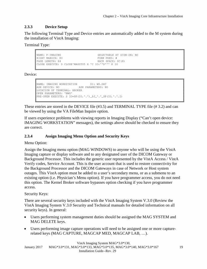
2.3.3 Device Setup The following Terminal Type and Device entries are automatically added to the M system during the installation of VistA Imaging:
Terminal Type: NAME: P-IMAGING SELECTABLE AT SIGN-ON: NO RIGHT MARGIN: 80 FORM FEED: # PAGE LENGTH: 64 BACK SPACE: $C(8) CLOSE EXECUTE: D CLOSE^MAGGTU5 X "C IO:""D""" K IO
Device: NAME: IMAGING WORKSTATION $I: WS.DAT ASK DEVICE: NO ASK PARAMETERS: NO LOCATION OF TERMINAL: BROKER OPEN PARAMETERS: "NWS" PRE-OPEN EXECUTE: S IO=$P(IO,".")_$J_"."_$P(IO,".",2)
These entries are stored in the DEVICE file (#3.5) and TERMINAL TYPE file (# 3.2) and can be viewed by using the VA FileMan Inquire option.
If users experience problems with viewing reports in Imaging Display (“Can’t open device: IMAGING WORKSTATION” messages), the settings above should be checked to ensure they are correct.
2.3.4 Assign Imaging Menu Option and Security Keys Menu Option:
Assign the Imaging menu option (MAG WINDOWS) to anyone who will be using the VistA Imaging capture or display software and to any designated user of the DICOM Gateway or Background Processor. This includes the generic user represented by the VistA Access / VistA Verify codes, Service Account. This is the user account that is used to restore connectivity for the Background Processor and the DICOM Gateways in case of Network or Host system outages. This VistA option must be added to a user’s secondary menu, or as a submenu to an existing option (i.e. Physician’s Menu option). If you have programmer access, you do not need this option. The Kernel Broker software bypasses option checking if you have programmer access.
Security Keys:
There are several security keys included with the VistA Imaging System V.3.0 (Review the VistA Imaging System V.3.0 Security and Technical manuals for detailed information on all security keys). In general:
• Users performing system management duties should be assigned the MAG SYSTEM and MAG DELETE keys.
• Users performing image capture operations will need to be assigned one or more capture-related keys (MAG CAPTURE, MAGCAP MED, MAGCAP LAB, …).

Chapter 2 – VistA Imaging Core Infrastructure Installation
VistA Imaging System MAG*3.0*130, January 2017 MAG*3.0*131, MAG*3.0*133, MAG*3.0*135, MAG*3.0*140, MAG*3.0*167 20 Installation Guide--Rev. 29
• Users of VistA Imaging Display will need to be assigned at least one of the two display-related keys (MAGDISP CLIN, MAGDISP ADMIN) depending on their duties.
• Only users assigned the MAG EDIT key can edit the indexing information associated with an image. The MAG EDIT key is used to correct an image field when an index field is incorrect or incomplete, such as correcting a wrong specialty that was selected. The MAG EDIT key and the MAG QA REVIEW key allow is also required to access to the QA Review Utility when performing quality assurance reviews of the scanned images. Only the Chief, HIM or authorized designated personnel (e.g., VistA Imaging Coordinator, Scanning Supervisor) should be assigned this key.
• Users who need to view only a patient photo should be assigned only to the MAG PAT PHOTO ONLY key.
• Users with the MAG ANNOTATE MGR key can add, edit, and delete annotations.
2.4 Background Processor Installation
2.4.1 Introduction The Background Processor software runs on a Windows-based server. It communicates with the VistA database by using the VistA RPC Broker.
• The purpose of the Background Processor is to manage the storage of clinical images at the time of capture to ensure that they are archived into a Tier 2 system.
• The Image files are aged or purged from Tier 1 storage after a period of disuse. This period of time is site configurable.
• The Image files that have been purged off of Tier 1are restored to Tier 1 when they are requested by VistA Imaging workstation activity.
• The purpose of this automatic file migration between servers is to provide a cost-effective mechanism to accelerate access to clinical images while insuring long-term availability.
2.4.2 Requirements & Functions Required software on a Background Processor server includes:
• Broker client agent 1.1 or later • Windows 2003 Server or later. • PCAnywhere V. 12.5 SP4 or later (recommended for remote support)
The Background Processor provides the following functions:
• Manages the file server share space
• Populates Tier 1 with image files that have most recently been viewed. (by moving files from Tier 2 to Tier 1)
• Manages the archiving of newly captured images to Tier 2
• Provides a mechanism for ad hoc deleting of image files

Chapter 2 – VistA Imaging Core Infrastructure Installation
VistA Imaging System MAG*3.0*130, January 2017 MAG*3.0*131, MAG*3.0*133, MAG*3.0*135, MAG*3.0*140, MAG*3.0*167 21 Installation Guide--Rev. 29
• Provides a mechanism for creating abstracts of images
• Provides a mechanism for purging images from Tier 1 when they have not been accessed within a time frame established by the management tools at each VistA site
• Provides status and alert messages to designated Mailman recipients
• Background Processor Verifier validates integrity of the image database
2.4.3 Distribution
The Background Processor software, Mag3_0P135BPSetup.exe, is distributed with VistA Imaging System. Three components are included in this file: the Queue Processor, the Verifier, and the Purge software.
The Background Processor software is client software that presumes the presence of the proper Imaging KIDS package on VistA. Refer to the most recent Imaging patch description for the Background Processor for compatibility information.
Once they are installed, the executables for the Background Processor applications are located in the folder Program Files\Vista\Imaging\BackProc and are named:
• Magbtm.exe – Queue Processor • MagVerifier.exe – Verifier • MagPurge.exe - Purge
2.4.4 Installation Instructions 1. On the system where the Background Processor will be installed, create a registry entry for
the Background Processor to communicate with the Broker on the VistA HIS:
Log in to the server as an administrator, start the Registry editor. If you are running Windows 2008 Server or other 64 bit OS, the VA Kernel RPC Broker configuration, host and port number, will need to be set in the following registry key: HKEY_LOCAL_MACHINE\SOFTWARE\Wow6432Node\Vista\Broker\Servers The registry key for 32 bit OS is in:
a. HKEY_LOCAL_MACHINE\Software\vista\Broker\Servers Create a new string value (Edit | New | String Value). Use the VistA server name and port number as the name of the value. Separate the name and the port number with a comma.
b. Close the Registry Editor.
2. You can install the Background Processor client while the VistA System is active. Installation takes less than two minutes.
3. Important: Make sure that the Background Processor client is not active when you attempt to install the MAG*3.0*135 client.

Chapter 2 – VistA Imaging Core Infrastructure Installation
VistA Imaging System MAG*3.0*130, January 2017 MAG*3.0*131, MAG*3.0*133, MAG*3.0*135, MAG*3.0*140, MAG*3.0*167 22 Installation Guide--Rev. 29
For 64 bit OS installs: 1. Log into the BP Server as an administrator.
2. For step 2 below, use the “Run As Administrator” option when installing BP Storage software on a 64 bit Windows OS, such as Win 2008 Server.
2.4.4.1 To install the Background Processor client: 1. Remove any previously installed versions of the VistA Imaging Background Processor using
the appropriate option in Control Panel:
2. • WIN 2003 SERVER: Start | Control Panel | Add or Remove Programs
3. • WIN 2008 SERVER: Start | Control Panel | Programs and FeaturesLocate and run the MAG3_0P135_BPSetup.exe file. This file is available on the Imaging FTP server under the folder Software\ Released Software\ MAG3_0P135
4. When the InstallShield wizard runs, accept the program defaults and click Next until the Ready to Install the Program dialog is displayed.
5. If the following message displays, click Yes.
6. Click Install to proceed with the installation.
7. When installation completes, click Finish to exit the installation wizard.
8. Start the Background Processor (Start | Programs | VistA Imaging Programs | Background Processor | Queue Processor). Then, choose Help | About to confirm that the software version is 30.5.135.nn.
9. Start the Verifier (Start | Programs | VistA Imaging Programs | Background Processor | Verifier). Then, choose Help | About to confirm that the software version is 30.5.135.nn.
10. Start the Purge (Start | Programs | VistA Imaging Programs| Background Processor | Purge). Then, choose Help | About to confirm that the software version is 30.5.135.nn.
11. If the installation is on a new server, create the desktop shortcuts for the Purge and the Verifier. The Background Processor Queue Processor shortcut/icon is automatically created on the desktop.
12. If you are installing the BP Queue Processor, BP Verifier, and BP Purge on a 64-bit operating system such as Windows 2008 Server, you need to manually set Run as administrator using the check box in the Advanced Properties window on each of the desktop shortcuts and the menu options. Do this for all three client applications.

Chapter 2 – VistA Imaging Core Infrastructure Installation
VistA Imaging System MAG*3.0*130, January 2017 MAG*3.0*131, MAG*3.0*133, MAG*3.0*135, MAG*3.0*140, MAG*3.0*167 23 Installation Guide--Rev. 29
If you install the MAG*3.0*135 Background Processor client before installing the MAG*3.0*135 KIDS, when you try to run the client, you will get a message informing you that the versions of the Background Processor client and the version of the VistA Imaging host system are not compatible and prompting you to install compatible versions of the Background Processor client and the VistA system host software. If you see such a message, complete the following steps:
1 Shut down the Background Processor client. 2 Install the MAG*3.0*135 KIDS. 3 Reinstall the MAG*3.0*135 Background Processor client.
13. If you are not able to install the MAG*3.0*135 KIDS, you will need to uninstall the MAG*3.0*135 client and reinstall the previous Background Processor client. Create a Background Processor server entry using the Edit | BP Server menu option located in the main window.
.

Chapter 2 – VistA Imaging Core Infrastructure Installation
VistA Imaging System MAG*3.0*130, January 2017 MAG*3.0*131, MAG*3.0*133, MAG*3.0*135, MAG*3.0*140, MAG*3.0*167 24 Installation Guide--Rev. 29
8. Click the Add New BP Server button to add the Background Processor to the BP SERVERS file (#2006.8). The Server Name field will automatically be updated with the server’s computer (NetBIOS) name.
9. Update the Logical Name field with a 3-character Background Processor identifier.
Example: BP1
10. Save the BP server record by clicking the Add button.
11. Create additional BP servers as needed.
Specify which tasks the Background Processor will process by dragging and dropping a task from the Unassigned Tasks section in the tree pane (shown) to the server that is designated to run that task.
By default, no tasks are assigned to BP Servers. The tasks will need to be assigned in order for that function of the BP software to operate. You can assign tasks based on the needs of your facility. As previously mentioned, a queue name identifies the task that the Queue Processor performs. All queues are available for you to assign to a BP Server, except EVAL. Note: You should assign Auto Purge as well as the Scheduled Verify to BP Servers. These features help maintain the system without operator monitoring and control.
• If a site has only one BP server, all queues should be assigned to it except PREFETCH.
• If there are multiple Background Processors, activities can be divided between them. However, the Abstract and JBTOHD queues must run on the same Background Processor, and the Jukebox and Delete queues must run on the same Background Processor.

Chapter 2 – VistA Imaging Core Infrastructure Installation
VistA Imaging System MAG*3.0*130, January 2017 MAG*3.0*131, MAG*3.0*133, MAG*3.0*135, MAG*3.0*140, MAG*3.0*167 25 Installation Guide--Rev. 29
Note: You cannot assign the same queue activity to two Background Processors. 12. Configure the Background Processor options in the Edit | Imaging Site Parameters menu. On
the window, check the Auto Write Location Update box so the Background Processor will automatically set the Current Image Write Location in the IMAGING SITE PARAMETERS file (#2006.1) to the online network location (magnetic) with the most available space. It will continuously adjust this value so all online shares fill at the same rate.
2.4.5 Imaging M File Setup The Background Processor, once installed, will need to be used to define image storage locations by editing the NETWORK LOCATION file (#2005.2). You will also need to check and adjust general Imaging parameters by editing the Imaging SITE PARAMETER file (#2006.1).
To perform the steps in following two sections, you will need to have the MAG SYSTEM security key assigned to your account.
Do not edit the Network Location or Imaging Site Parameter files using FileMan. Using the Background Processor will reduce the potential of entering invalid field data. (Some field changes will require FileMan usage.)
2.4.5.1 Edit the NETWORK LOCATION File (#2005.2)
All file server folders to be used by the VistA Imaging System for storing images must be listed in the Network Location file. Each one is assigned a logical name. Magnetic storage entries begin with “MAG”. All optical entries should start with “WORM”. All network locations (magnetic and optical) should be configured as “hashed” network locations. A hashed network location has a hierarchical directory structure for storing images. The VistA Imaging software uses a directory structure with 100 base file names or directories in each directory. The location of the file is calculated from the file name as shown below:
The file CBA00123456789.TGA would be stored in \CBA0\01\23\45\67. The full path would be:
\\VHAxxxCLUx\IMAGEx$\CBA0\01\23\45\67\CBA00123456789.TGA
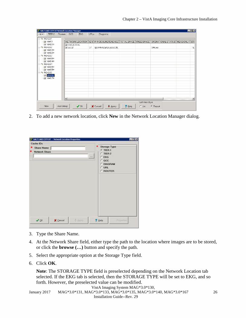
1. Open the Background Processor application and select Edit | Network Location Manager.
Chapter 2 – VistA Imaging Core Infrastructure Installation
VistA Imaging System MAG*3.0*130, January 2017 MAG*3.0*131, MAG*3.0*133, MAG*3.0*135, MAG*3.0*140, MAG*3.0*167 26 Installation Guide--Rev. 29
2. To add a new network location, click New in the Network Location Manager dialog.
3. Type the Share Name.
4. At the Network Share field, either type the path to the location where images are to be stored, or click the browse (…) button and specify the path.
5. Select the appropriate option at the Storage Type field.
6. Click OK.
Note: The STORAGE TYPE field is preselected depending on the Network Location tab selected. If the EKG tab is selected, then the STORAGE TYPE will be set to EKG, and so forth. However, the preselected value can be modified.

Chapter 2 – VistA Imaging Core Infrastructure Installation
VistA Imaging System MAG*3.0*130, January 2017 MAG*3.0*131, MAG*3.0*133, MAG*3.0*135, MAG*3.0*140, MAG*3.0*167 27 Installation Guide--Rev. 29
7. If your site created multiple image shares, add a new network location for each of the remaining shares.
Note: If a share becomes unavailable at any time during operation, you can set it offline by unchecking Operational Status, as explained in section 6.1.4.1 Editing the Network Location Operational Status Field. This will flag VistA Imaging Clinical Display software to retrieve any images that reside on this offline share from the Tier 2 share instead.
2.4.5.2 Edit the IMAGING SITE PARAMETERS File (#2006.1)
The fields in the IMAGING SITE PARAMETERS file (#2006.1) reflect the system wide VistA Imaging Parameters. The VistA Imaging KIDS installation package sets defaults for most of the required fields.
1. Launch the Background Processor application and select the Edit | Imaging Site Parameters menu.
The Site Parameter dialog will display showing the current defaults.
2. Press F1 for context sensitive help on each field or click the Help button for general help.
3. Set up the service accounts using the descriptions below as a guide.
These credentials are shared between the DICOM Gateway, Image cluster, Tier 2 Server, and Background Processor.

Chapter 2 – VistA Imaging Core Infrastructure Installation
VistA Imaging System MAG*3.0*130, January 2017 MAG*3.0*131, MAG*3.0*133, MAG*3.0*135, MAG*3.0*140, MAG*3.0*167 28 Installation Guide--Rev. 29
Field or Checkbox Description Windows Username Imaging Administrator domain Service Account (IA
Account) used to access the Imaging shares on the RAID and archive (jukebox) share. Both the Tier 1 and Tier 2 shares must have READ/WRITE permission to this account.
Windows Password Domain password used to access the Imaging shares on the Tier 1 and Tier 2 share.
VistA Access Encrypted access code for the Imaging Service Account in VistA. This account will be used to automatically re- log into the application when there is a loss of connectivity between the BP product and the Broker (VistA). Note: The Imaging Service Account must have the MAG SYSTEM security key and secondary menu option MAG WINDOWS. The VERIFY CODE never expires. This user must have a single division designation.
VistA Verify Encrypted verify code for the Imaging Service Account in VistA. This account will be used to automatically re- log into the application when there is a loss of connectivity between the BP product and the Broker (VistA).
4. Add the VistA Imaging IRM staff member(s) and VistA Imaging ADPAC to the local VistA Imaging Mail group. They will need the MAG SYSTEM security key in order to be visible in the members list in the GUI. It is strongly recommended to leave the Remote Member [email protected] in place. This mail group provides information to the VistA Imaging Development and support teams on a monthly basis and also sends critical low free space messages. The site may wish to add their pager email address to the Remote Members in order to receive pages on text capable pagers. The domain portion of the remote member’s email address must be defined in VistA’s Domain file.
Note: The Current Namespace field is not editable. (Please enter a Remedy call if your site desires a change to this field.)
5. Edit the Purge parameters. These are accessed from the Edit | Purge Parameters menu on the Background Processor main form. Each number entered represents the number of days a file type will remain on magnetic storage after its last user access. The number can be adjusted to find a good ratio of magnetic server free space to number of days image files remain online.

Chapter 2 – VistA Imaging Core Infrastructure Installation
VistA Imaging System MAG*3.0*130, January 2017 MAG*3.0*131, MAG*3.0*133, MAG*3.0*135, MAG*3.0*140, MAG*3.0*167 29 Installation Guide--Rev. 29
Factors in determining this ratio are: number of studies performed, size of studies and amount of magnetic RAID storage purchased at the site.
Important: Imaging Site Parameter setup will continue with the Tier 2 setup. See section 2.4.6.1 Updating VistA Files for Tier 2 Using the Background Processor.
2.4.6 Tier 2 Software Installation The Optical Technology Group’s (OTG) MediaStor and DiskXtender software is used to control file migration to and from Tier 2. When installed, the Tier 2 appears on the network as a share that can be accessed from any client workstation and the background processor. The share spans all platters in Tier 2, which gives the appearance of one large magnetic drive. Windows directory-style security is used to limit access to the share.
It is recommended that you have your Tier 2 hardware set up by the vendor. General Tier 2 hardware maintenance tasks are described in Appendix C.
2.4.6.1 Updating VistA Files for Tier 2 Using the Background Processor In order for the Background Processor to copy files to and from Tier 2, a network location must be defined in the NETWORK LOCATION file (#2005.2). Add the new network location by using the configuration utilities of the Background Processor.
1. Open the Background Processor application and select Edit | Network Location Manager from the menu bar.
2. Select the Tier 2 tab.
3. Click New in the Network Location Manager window to open the Network Location Properties window.

Chapter 2 – VistA Imaging Core Infrastructure Installation
VistA Imaging System MAG*3.0*130, January 2017 MAG*3.0*131, MAG*3.0*133, MAG*3.0*135, MAG*3.0*140, MAG*3.0*167 30 Installation Guide--Rev. 29
4. At the Share Name field, specify WORMOTG{n} for the network location.

Chapter 2 – VistA Imaging Core Infrastructure Installation
VistA Imaging System MAG*3.0*130, January 2017 MAG*3.0*131, MAG*3.0*133, MAG*3.0*135, MAG*3.0*140, MAG*3.0*167 31 Installation Guide--Rev. 29
5. At the Network Share field, set the Physical reference to: \\VHAxxxIMMx\IMAGEJB1$. Note: Clustered Tier 2 would have the cluster name instead of the server name.
6. Press <tab>. The Storage Type: Tier 2 should already be selected.
7. Press <tab> and click OK. 8. To activate this share as the default Tier 2 write location, select Edit | Imaging Site
Parameters from the menu bar.
9. In the Storage Functions group, select it as the default Tier 2 write location.
2.4.7 Monitoring BP Servers Description The BP Monitor is a utility that sites can configure to monitor the activity of BP Server(s) in the VistA Imaging system. The utility sends an e-mail when one or more BP Servers are not operating properly and it monitors the assigned tasks of BP Server(s) to determine if:
• A task is lagging behind.
• The task has too many failed queues.
• A scheduled task has not executed.
The utility enables the Imaging Coordinator to evaluate the BP Server(s) to determine whether a network traffic problem exists, and to maintain the tasks effectively.
Setup
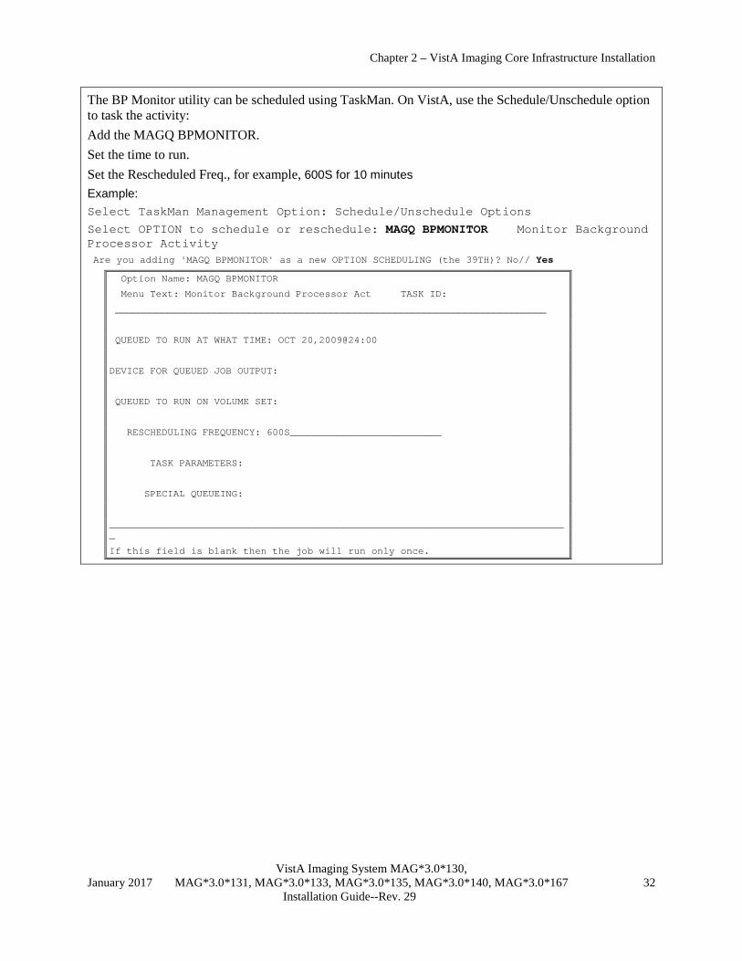
Chapter 2 – VistA Imaging Core Infrastructure Installation
VistA Imaging System MAG*3.0*130, January 2017 MAG*3.0*131, MAG*3.0*133, MAG*3.0*135, MAG*3.0*140, MAG*3.0*167 32 Installation Guide--Rev. 29
The BP Monitor utility can be scheduled using TaskMan. On VistA, use the Schedule/Unschedule option to task the activity: Add the MAGQ BPMONITOR. Set the time to run. Set the Rescheduled Freq., for example, 600S for 10 minutes Example: Select TaskMan Management Option: Schedule/Unschedule Options
Select OPTION to schedule or reschedule: MAGQ BPMONITOR Monitor Background Processor Activity Are you adding 'MAGQ BPMONITOR' as a new OPTION SCHEDULING (the 39TH)? No// Yes
Option Name: MAGQ BPMONITOR
Menu Text: Monitor Background Processor Act TASK ID:
__________________________________________________________________________
QUEUED TO RUN AT WHAT TIME: OCT 20,2009@24:00
DEVICE FOR QUEUED JOB OUTPUT:
QUEUED TO RUN ON VOLUME SET:
RESCHEDULING FREQUENCY: 600S__________________________
TASK PARAMETERS:
SPECIAL QUEUEING:
_______________________________________________________________________________
If this field is blank then the job will run only once.

Chapter 2 – VistA Imaging Core Infrastructure Installation
VistA Imaging System MAG*3.0*130, January 2017 MAG*3.0*131, MAG*3.0*133, MAG*3.0*135, MAG*3.0*140, MAG*3.0*167 33 Installation Guide--Rev. 29
The MAGQ BPMONITOR has additional optional parameters that can be set when it is tasked. At the command line, type NEXT to display additional scheduling parameters. Optional parameters are:
• MAGFQ, the variable for the sensitivity value for failed queues. If it is not defined, it defaults to 1000.
• MAGMIN, the variable for the sensitivity value for the time lapse between queue processing. If it is not set, it defaults to 15 minutes. Adjust the sensitivity value according to Imaging’s network topology. For example, if the Imaging’s network is not local then increase the value.
• MAGEVAL, the variable for the sensitivity value for EVAL queues. If it is not set, it defaults to 10,0000. Adjust the sensitivity value accordingly to your Routing network topology and the average daily number of images routed. A sensitivity value of 10,000 may be too low for a site that heavily routes images.
Edit Option Schedule
Option Name: MAGQ BPMONITOR
_____________________________________________________________________
USER TO RUN TASK: ___________________________________
VARIABLE NAME: MAGFQ VALUE: 50
VARIABLE NAME: MAGMIN VALUE: 25
VARIABLE NAME: MAGEVAL VALUE: 25000
VARIABLE NAME: VALUE:
VARIABLE NAME: VALUE:
_______________________________________________________________________________
COMMAND:
2.5 Imaging Workstation Setup
2.5.1 Overview of Installation of Imaging Workstation Software Review the following information:
Please verify that your workstation hardware is currently supported by the VistA Imaging Project by reviewing the Planning Document and Approved Equipment List. This document can be downloaded from the VistA Imaging SharePoint site at:
• http://vaww.oed.portal.va.gov/applications/VistAImaging/default.aspx

Chapter 2 – VistA Imaging Core Infrastructure Installation
VistA Imaging System MAG*3.0*130, January 2017 MAG*3.0*131, MAG*3.0*133, MAG*3.0*135, MAG*3.0*140, MAG*3.0*167 34 Installation Guide--Rev. 29
The following steps are required to load the operational VistA Imaging System software onto the workstations:
1. Install the latest Windows operating system approved by the VA. 2. Install Kernel Broker client agent Client Agent software. 3. Install Sentillion Vergence Desktop Components. 4. Install VistA Imaging workstation software. 5. Edit the Imaging workstation configuration files according to the steps listed in section
2.5.7.
2.5.2 Install the Latest Windows Operating System Approved by the VA Install the Windows operating system on the workstation and set up local security policies and virus protection. The workstation display resolution should be set to 1024 x768 or higher and the color palette should be set to True Color (or the highest available color palette setting). Windows should be installed and configured similar to any other workstation in the Medical Center.
2.5.3 Install RPC Broker Client Software The following summarizes the installation of the RPC Broker Client Agent software. See the RPC Broker installation manual for more detailed information.
1. Log in to workstation as an administrator
2. Install the RPC Broker client agent software
a. Run XWB1_xWS.EXE and follow the setup wizard. Accept all defaults and answer “Yes” when given the option of running the Client Agent program on startup.
b. Run the Kernel Broker test program. Enter the fully qualified domain name of your VistA server in the Server field. In the port field, enter the port number that the VistA RPC broker is listening on.
RPCTest.exe is a test program distributed and installed on your PC in the C:\Program Files\VISTA\BROKER folder when the Kernel Broker Client Agent software is installed. When executed, it can be used to test the connection to the VistA System. This is valuable in troubleshooting problems with the VistA Imaging System. Please review the Kernel Broker documentation for more information and examples on the test application.
2.5.4 Install Sentillion Vergence Desktop Components The Sentillion Vergence Desktop Components provide communication between CCOW-enabled applications for synchronizing participating applications to the same patient and user. In order to use CCOW on a workstation, the workstation must have the desktop components configured to use the site’s Sentillion Vergence Vault.
If your site is using CCOW for Context Management, install the Sentillion Vergence Desktop components on each client workstation. For detailed instructions on installing and configuring the desktop components or the vault, please see the Vergence Desktop Components Installation

Chapter 2 – VistA Imaging Core Infrastructure Installation
VistA Imaging System MAG*3.0*130, January 2017 MAG*3.0*131, MAG*3.0*133, MAG*3.0*135, MAG*3.0*140, MAG*3.0*167 35 Installation Guide--Rev. 29
Instructions at http://vaww.eie.va.gov/SysDesign/HSED/CCOW/default.aspx or log a Remedy ticket.
2.5.5 Install the VistA Imaging Workstation Software These sections explain how to install the Imaging workstation software (Clinical Display, Clinical Capture, and TeleReader) using the following methods:
• Single workstation installation
• Remote push installation to multiple workstations using PSExec
• Remote push installation using Microsoft System Center Configuration Manager or other software management programs.
Installation requires approximately 200 MB of disk space. Installation must be performed using an administrative account.
2.5.5.1 Single Workstation Installation For local installation on a single workstation, you will need the clinical client installer files.
You can get the files from the VistA Imaging FTP Site. The names of the installers of the Clinical Display, Clinical Capture, and TeleReader clients use these patterns:
• TeleReader installer files: MAG3_0{PatchNumber}_TeleReaderInstall.msi MAG3_0{PatchNumber}_TeleReaderSetup.exe
• Clinical Display installer files: MAG3_0{PatchNumber}_Clinical_Display_Install.msi MAG3_0{PatchNumber}_ Clinical_Display_Setup.exe
• Clinical Capture installer files: MAG3_0{PatchNumber}_Clinical_Capture_Install.msi MAG3_0{PatchNumber}_ Clinical_Capture_ Setup.exe
Clinical Display is distributed as an MSI and EXE installation. The MSI is intended for sites that want to do a push installation (using SCCM or another tool). If you are installing Clinical Display on a single workstation, use the EXE file. Clinical Display MAG*3.0*131 and later patches require Microsoft Visual C++ runtime. If Microsoft Visual C++ runtime is not installed on the workstation and you are installing the application using the EXE file, a window displays prompting you to install Microsoft Visual C++ runtime. If you are using the MSI file, you must install Microsoft Visual C++ runtime environment before you start the installation.
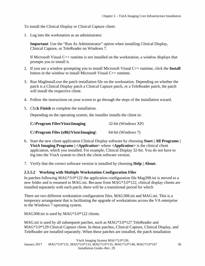
Chapter 2 – VistA Imaging Core Infrastructure Installation
VistA Imaging System MAG*3.0*130, January 2017 MAG*3.0*131, MAG*3.0*133, MAG*3.0*135, MAG*3.0*140, MAG*3.0*167 36 Installation Guide--Rev. 29
To install the Clinical Display or Clinical Capture client:
1. Log into the workstation as an administrator.
Important: Use the “Run As Administrator” option when installing Clinical Display, Clinical Capture, or TeleReader on Windows 7.
If Microsoft Visual C++ runtime is not installed on the workstation, a window displays that prompts you to install it.
2. If you see a window prompting you to install Microsoft Visual C++ runtime, click the Install button in the window to install Microsoft Visual C++ runtime.
3. Run MagInstall.exe the patch installation file on the workstation. Depending on whether the patch is a Clinical Display patch a Clinical Capture patch, or a TeleReader patch, the patch will install the respective client.
4. Follow the instructions on your screen to go through the steps of the installation wizard.
5. Click Finish to complete the installation.
Depending on the operating system, the installer installs the client in:
C:\Program Files\Vista\Imaging 32-bit (Windows XP)
C:\Program Files (x86)\Vista\Imaging\ 64-bit (Windows 7)
6. Start the new client application Clinical Display software by choosing Start | All Programs | VistA Imaging Programs | <Application> where <Application> is the clinical client application, which you installed. For example, Clinical Display 32-bit. You do not have to log into the VistA system to check the client software version.
7. Verify that the correct software version is installed by choosing Help | About.
2.5.5.2 Working with Multiple Workstation Configuration Files In patches following MAG*3.0*122 the application configuration file Mag308.ini is moved to a new folder and is renamed to MAG.ini. Because from MAG*3.0*122, clinical display clients are installed separately with each patch, there will be a transitional period for which
There are two different workstation configuration files, MAG308.ini and MAG.ini. This is a temporary arrangement that is facilitating the upgrade of workstations across the VA enterprise to the Windows 7 operating system.
MAG308.ini is used by MAG*3.0*122 clients.
MAG.ini is used by all subsequent patches, such as MAG*3.0*127 TeleReader and MAG*3.0*129 Clinical Capture client. In these patches, Clinical Capture, Clinical Display, and TeleReader are installed separately. When these patches are installed, the patch installation

Chapter 2 – VistA Imaging Core Infrastructure Installation
VistA Imaging System MAG*3.0*130, January 2017 MAG*3.0*131, MAG*3.0*133, MAG*3.0*135, MAG*3.0*140, MAG*3.0*167 37 Installation Guide--Rev. 29
program copies MAG308.ini to MAG.ini and places MAG.ini in a different directory. The patch client then uses MAG.ini.
If there are any MAG*3.0*122 clients on the workstation, they use MAG308.ini. If there are no MAG*3.0*122 or earlier patches on the workstation, all clients use MAG.ini. If MAG*3.0*122 or earlier patches were never installed on the workstation, MAG308.ini will not be present on that workstation.
In patch MAG*3.0*122 and earlier patches, the file Mag308.ini file was located in the application directory. This is illustrated in the following table.
Table 1: Paths to MAG*3.0*122 Configuration Files
Windows XP 32-bit Clinical Display C:\Program Files \Vista\Imaging\MAG308.ini Clinical Capture C:\Program Files \Vista\Imaging\MAG308.ini TeleReader C:\Documents and Settings\All Users\Application Data\Vista\Imaging\MAG308.ini TeleReader Configurator C:\Documents and Settings\All Users\Application Data\Vista\Imaging\
MagTeleReaderConfig.ini.
In patches that follow MAG*3.0*122, the path to the workstation configuration files on your computer depends on whether your workstation has a 32-bit or 64-bit operating system. The following table lists the locations of the configuration files for the supported platforms for patches that follow MAG*3.0*122. Paths to Configuration Files for Patches Released After MAG*3.0*122 MAG.ini
Windows XP 32-bit Windows 7 64-bit Clinical Display C:\Documents and Settings\All Users\Application
Data\Vista\Imaging\MAG.ini C:\ProgramData\Vista\Imaging\MAG.ini
Clinical Capture
C:\Documents and Settings\All Users\Application Data\Vista\Imaging\MAG.ini
C:\ProgramData\Vista\Imaging\MAG.ini
TeleReader C:\Documents and Settings\All Users\Application Data\Vista\Imaging\MAG.ini
C:\ProgramData\Vista\Imaging\MAG.ini
TeleReader Configurator
C:\Documents and Settings\All Users\Application Data\Vista\Imaging\ MagTeleReaderConfig.ini. C:\ProgramData\Vista\Imaging\MagTeleRea
derConfig.ini
2.5.5.3 Remote Display Login Setup The steps outlined in this section will allow you to configure the clinical imaging software to prompt a user to choose from a list of sites to connect to.
To allow clinical imaging software to log into a remote site, you will need to edit the workstation’s registry. The registry can be edited directly using Regedit (as described below), or by using the Edit Broker Server utility distributed with the Broker development toolkit (as described RPC Broker Systems Manual). You may also need to edit the HOSTS file.
Note: These modifications are only necessary if you want to log into a remote VistA database. If you wish to view images for a patient from a remote site, you can do this by utilizing remote image views functionality. For more information, see chapter 18 of the VistA Imaging Technical Manual.

Chapter 2 – VistA Imaging Core Infrastructure Installation
VistA Imaging System MAG*3.0*130, January 2017 MAG*3.0*131, MAG*3.0*133, MAG*3.0*135, MAG*3.0*140, MAG*3.0*167 38 Installation Guide--Rev. 29
Use caution when editing the registry manually. Improper changes can leave your system unstable or non-functional.
You will need the fully qualified domain name and port number of the remote site’s VistA server that runs the Broker server to complete these steps.
To set up remote login 1. Log into the workstation as an administrator, start the Registry Editor (Start | Run | Regedit)
and navigate to: HKEY_LOCAL_MACHINE\Software\vista\Broker\Servers
2. Create a new string value (Edit | New | String Value). Use the remote VistA server name and port number as the name of the value. Separate the name and the port number with a comma. Use the fully qualified domain name whenever possible.
3. Close the Registry Editor.
4. If the server name does not resolve through DNS, add the server name to the open the HOSTS file as demonstrated below. This file is located in WINDOWS\system32\drivers\etc.
Note: Using the HOSTS file to resolve IP addresses is not recommended and should only be used as a last resort.
Add a line that includes the IP address and name of the remote site’s Broker server. #HOSTS 10.2.1.1 Washington 10.2.1.2 Baltimore #END
5. Using the instructions in the workstation configuration file Settings section, modify the AllowRemoteLogin entry in the Login Options section and set its value to TRUE.
Open the workstation configuration file.

Chapter 2 – VistA Imaging Core Infrastructure Installation
VistA Imaging System MAG*3.0*130, January 2017 MAG*3.0*131, MAG*3.0*133, MAG*3.0*135, MAG*3.0*140, MAG*3.0*167 39 Installation Guide--Rev. 29
The path to the workstation configuration file varies depending on the operating system of your computer.
In the Login Options section, change the values of Local VistA and Local VistA Port entries. The Value of Local VistA should be set to the fully qualified domain name of your VistA server and the value of the Local VistA Port should be the port number RPC broker listens to for the incoming client connections.
2.5.5.4 Separate Installations of Clinical Applications Previous releases of VistA Imaging Clinical applications have included the three applications that comprise the VistA Imaging workstation software (Clinical Display, Clinical Capture, and TeleReader) in one installation. However, clinical patches released after MAG*3.0*122 may install a single client application. As a result, there will be different versions of TeleReader, Clinical Capture, and Clinical Display on the same workstation. For details on how this affects the uninstall process, see section 2.7.
2.5.5.5 Remote Push Installation Using PSExec Remote installation allows the Imaging software to be installed on multiple workstations remotely instead of requiring an administrator to sit down at each workstation. Administrators can customize the install process to fit their needs.
The following files are used to perform a remote push installation. These files are available on the VistA Imaging FTP Site.
Clinical client installer – A file with a name like MAG3_0P{PatchNumber}_{Component}Install.exe. For example, MAG3_0P129_ Clinical_Capture_Setup.exe psexec.exe – Freeware tool used to execute commands on remote machines wkstlist.txt – Text file listing target workstations for installation
MagInstallPush.bat – Remote installation script. Includes command line options that can modify the behavior of PSExec and the clinical workstation installation files.
When performing a remote installation, target workstations must be powered on, and the account used to initiate the push must have administrative privileges on all workstations where the software is to be installed. The following steps explain how to perform remote installations. These steps can be used to install Imaging on new workstations, or to update software on existing workstation.
Important: Replace the variable {Installer} in the following instructions with the name of the clinical client installer.

Chapter 2 – VistA Imaging Core Infrastructure Installation
VistA Imaging System MAG*3.0*130, January 2017 MAG*3.0*131, MAG*3.0*133, MAG*3.0*135, MAG*3.0*140, MAG*3.0*167 40 Installation Guide--Rev. 29
To perform a remote installation 1. Copy the following files to a location that can be accessed by the machine that will be
performing the push.
{Installer} psexec.exe wkstlist.txt MagInstallPush.bat
Note: Do NOT make the {Installer} file read-only. If this file is read only, errors will be encountered when future remote pushes are performed.
Note: The commands in MagInstallPush.bat assume that all needed files are in the same folder as MagInstallPush.bat.
2. In MagInstallPush.bat, review the commands to be passed to PSExec. Pre-defined commands are indicated in the sample below. It is recommended that these commands not be changed.
for /f "tokens=1" %%i in (WKSTLIST.TXT) do psexec %%i -i -c -d {Installer} /v"/qb"
• Pre-defined PSExec commands are described below. A complete list of commands can be displayed by typing “psexec” at the command prompt in the directory where psexec.exe resides.
-i Allow interactive installation on the remote machine.
-c Copy MagInstall.exe to the remote machine before executing, eliminating the need for the remote machine to connect to a network location to access MagInstall.exe.
-d Allows installation to be triggered on successive machines without waiting for each installation to complete.
• Additional commands can be added as needed. Separate command with spaces, and DO NOT remove the “%%i” parameter.
3. In MagInstallPush.bat, review the commands to be passed to MSIExec (which handles the installation of the clinical client installer). Default commands are indicated in the sample below.
for /f "tokens=1" %%i in (WKSTLIST.TXT) do psexec %%i -i -c -d {Installer} /v"/qb"
• Additional commands can be added as needed. Separate commands with spaces, and DO NOT remove the “ /v”” parameter.
• The /qb command allows the display of a progress bar during installation. A complete list of command line parameters can be found at: http://msdn.microsoft.com/library/default.asp?url=/library/en-us/msi/setup/command_line_options.asp.
4. Save and close MagInstallPush.bat.
5. Open wkstlist.txt and enter the name of each workstation where the software will be installed. List one name per line, and precede each line with “\\”

Chapter 2 – VistA Imaging Core Infrastructure Installation
VistA Imaging System MAG*3.0*130, January 2017 MAG*3.0*131, MAG*3.0*133, MAG*3.0*135, MAG*3.0*140, MAG*3.0*167 41 Installation Guide--Rev. 29
\\workstation1 \\workstation2 \\workstation3
6. After preparing all needed files, run MagInstallPush.bat. Ideally, wait for a period of reduced system usage to do so. Sample output from a command line is shown below.
C:\Temp>MagInstallPush
C:\Temp>for /F "tokens=1" %i in (WKSTLIST.TXT) do psexec %i -i -c -d {Installer} /v"/qb"
C:\Temp>psexec \\workstation1 -i -c -d {Installer} /v"/qb"
PsExec v1.43 - execute processes remotely Copyright (C) 2001-2003 Mark Russinovich www.sysinternals.com
{Installer} started on workstation1 with process ID 716.
Note: If Display or Capture software is running on a target workstation when a push is performed, the user will have the option to cancel the installation, or to exit the Display or Capture program and continue the installation.
2.5.5.6 Remote Push Installation Using Microsoft System Center Configuration Manager The {Installer}.msi file (the clinical Capture or Clinical Display client installer file with a name like MAG3_0P{PatchNumber}_{Component}Install.msi) is available on the Imaging FTP site. This file can be used with Microsoft System Center Configuration Manager (SCCM) or similar software management applications for automated installation on workstations. Implementation details are site specific.
Clinical Display MAG*3.0*131 and later patches require Microsoft Visual C++ runtime if not already installed on the workstation. If you are installing either MAG*3.0*131 or doing in initial installation of a subsequent patch you must install the following on the workstations before installing the Clinical Display client:
• Microsoft Visual C++ 2005 runtime redistributable • Microsoft Visual C++ 2010 runtime redistributable
Be sure to get the x86 version of these runtimes because the Display client is an x86 executable.
After the initial installation of the Imaging (Clinical Display and& Clinical Capture) software additional setup may be required.
The Clinical Display MSI distribution which should be used for push installations does not include the required Microsoft visual C++ runtime versions described above. These must be installed prior to installing the Clinical Display application using the MSI.
2.5.6 Setting Up and Using Autoupdate
Autoupdate is no longer a supported function of VistA Imaging.

Chapter 2 – VistA Imaging Core Infrastructure Installation
VistA Imaging System MAG*3.0*130, January 2017 MAG*3.0*131, MAG*3.0*133, MAG*3.0*135, MAG*3.0*140, MAG*3.0*167 42 Installation Guide--Rev. 29
2.5.7 Edit the Imaging Workstation Configuration File with the MAGSYS Tool After installing Clinical Display or Capture software, the workstation configuration file (MAG308.INI) will need to be edited to enable or configure certain features.
Note: Do not edit MAG308.INI manually. Use the Workstation Configuration Editor to edit MAG308.INI.
2.5.7.1 Workstation Configuration Summarized To access MAG308.INI, start the Workstation Configuration Editor from the Display, Capture, or Site Manager Tools programs.
MAG308.INI is divided into multiple sections, where each section is displayed on the left side of the configuration editor window. Entries and values for a selected section are shown on the right side of the window.
For Display workstations, review entries in the following sections:
[Login Options] [Workstation Settings] [Remote Site Options]
For Capture workstations, review entries in the following sections:
[Button/Field Options] [Login Options] [Image Format] [Medicine Options] [Import Options] [Save Options] [Input Source] [Association] [Input Source Options] [Workstation Settings]
For additional details, see sections 2.5.7.2 and 2.5.7.3.
2.5.7.2 Using the Workstation Configuration Editor The Workstation Configuration Editor is used to edit The Workstation Configuration Editor is used to edit MAG308.INI. Access to the editor is limited to users who have the MAG SYSTEM key.
Editing the contents of MAG308.INI
1. Start the Workstation Configuration editor by doing one of the following:
• Start the Site Manager Tools program (C:\Program Files\Vista\Imaging\ MAGSYS.EXE). Click the VistA button to log in, and then click Configure.
• Log into Clinical Display and choose the System Manager | Open Workstation Configuration Window menu option.
• Log into Clinical Capture and choose the System Manager | Workstation Configuration Editor menu option.

Chapter 2 – VistA Imaging Core Infrastructure Installation
VistA Imaging System MAG*3.0*130, January 2017 MAG*3.0*131, MAG*3.0*133, MAG*3.0*135, MAG*3.0*140, MAG*3.0*167 43 Installation Guide--Rev. 29
2. When the editor starts, MAG308.INI is automatically opened. In the left side of the window, locate the section you want to edit.
3. Select the section, then the entry you want to change.
• TRUE/FALSE values can be changed by double clicking the actual value, or by clicking one of the options displayed in the bottom of the window.
• Other values can be changed by either entering free text or choosing one of the options in the ‘value =’ box.
4. To save changes click the ‘Save’ button or ‘Save’ menu option. To cancel changes click the ‘Cancel’ button.
Note: Changes to MAG308.INI will not affect a currently running session of Clinical Capture or Display. To make changes take effect, restart the program.

Chapter 2 – VistA Imaging Core Infrastructure Installation
VistA Imaging System MAG*3.0*130, January 2017 MAG*3.0*131, MAG*3.0*133, MAG*3.0*135, MAG*3.0*140, MAG*3.0*167 44 Installation Guide--Rev. 29
2.5.7.3 Workstation Configuration File (MAG308.INI) Settings Each MAG308.INI section is described below. Sections are listed alphabetically. Entries are listed in the order they appear in the Workstation Configuration Editor.
Note: Do not edit MAG308.INI manually. Use the Workstation Configuration Editor to edit MAG308.INI.
[Button/Field Options] This section controls the behavior of the Image Description box in the main Capture window. Entries in the [Button/Field Options] section are listed below.
[Button/Field Options] Section Entries
Name Details Default
CreateDefault ImageDesc
When set to TRUE, a default description is automatically entered in the Image Description box for captured images. The default description is based on the selected procedure and the capture date. It is recommended that this entry is always set to TRUE. The user can modify the default image description if needed.
TRUE
ImageDesc Controls the cursor position and text selection behavior in the Image Description box. One of the following values can be specified:
Selected (Windows default) - Text in the box will be selected, typing by user will overwrite text. NoSelectCursorEnd - Typing by user will be added to the end of the default text. NoSelectCursorHome - Typing by user will be inserted at the beginning of the default text.
The last two options allow users to enter text at the beginning or end of a description without the annoying need to first de-select the text or reposition the cursor. They are intended for users capturing groups of images.
Selected
[Demo Options] The options in this section are intended for internal testing and should not be changed.
[Image Format] This section controls which image formats are enabled for user selection during image captures.
For Capture workstations, at least one entry in this section must be set to TRUE, and the Default entry must be set to something other than NONE.
An enabled image format should correspond to one or more input sources enabled in the [Input Source] section.

Chapter 2 – VistA Imaging Core Infrastructure Installation
VistA Imaging System MAG*3.0*130, January 2017 MAG*3.0*131, MAG*3.0*133, MAG*3.0*135, MAG*3.0*140, MAG*3.0*167 45 Installation Guide--Rev. 29
Example At a workstation connected to a Lumisys scanner, only the Xray Image Source would be enabled. At a workstation connected to flatbed color scanner, both the True Color JPG and Document TIF G4 FAX image formats might be enabled.
Only the formats that will be used at a particular workstation should be enabled.
Note: During image capture, the image format selected by the user determines the graphics file format that the image is saved as. The file format of the image dictates which viewer will be used to display the image in Clinical Display.
Entries in the [Image Format] section are listed below. Unless otherwise stated, TRUE (enable) and FALSE (disable) are the only valid values.
[Image Format] Section Entries
Name Details Default
True Color TGA 24- or 32-bit color image in TARGA format. FALSE
True Color JPG 24- or 32-bit color image in JPEG format. Image source will determine if lossy or lossless compression is used.
FALSE
256 Color 8-bit color image in TARGA format. FALSE
Xray 8- or 12-bit grayscale TARGA image. FALSE
Xray JPG 8- or 12-bit grayscale JPEG image. FALSE
Black and White 8-bit grayscale TARGA image for ultrasound, cardiac catheterization, and pathology stain images.
FALSE
Document TIF Uncompressed
1-bit uncompressed TIF image. (Not recommended for document scanning. Uncompressed TIF images can be very large.)
FALSE
Document TIF G4 FAX 1-bit compressed 300 x 300 TIF image. Use for scanned documents.
FALSE
Bitmap 24-bit color image in bitmap format. FALSE
DICOM Image in DICOM format FALSE
Use Format of Imported Image
When Import is the Image Source, this is the only enabled Image Format. The application will determine the value of certain image fields based on the image format. User is not able to select a format when import is the source.
FALSE
[Import Options] This section controls how Clinical Capture handles imported images. Options in this section take affect only if Import is enabled in the [Input Source] section.
Note: The following import formats are supported: ABS, ASC, AVI, BIG, BMP, BW, DCM, DOC, HTM, HTML, JPG, MP3, MP4, MPEG, MPG, PAC, PDF, RTF, TGA, TIF, TXT, and WAV.

Chapter 2 – VistA Imaging Core Infrastructure Installation
VistA Imaging System MAG*3.0*130, January 2017 MAG*3.0*131, MAG*3.0*133, MAG*3.0*135, MAG*3.0*140, MAG*3.0*167 46 Installation Guide--Rev. 29
[Import Options] Section Entries
Name Details Default
Type Determines the format of a file captured as an imported file. One of the following values can be specified.
Convert to TGA - Saves the imported image as an uncompressed TGA file. Convert File Format to Default - Saves the imported image as the currently selected Image Format. A selected Image Format must be enabled in the [Image Format] section, and is limited to TGA, TIF, and JPG formats. Copy to Server - The file extension and format of the copied file will be the same as that of the original file.
Note: Copy to Server should be used for compressed file formats (such as JPG) to avoid recompressing the file and further reducing image quality.
Copy to Server
DefaultImportDir A free text value that specifies the initial default directory to be displayed in the directory lookup area when importing images. The default directory is C:\Program Files\VistA\Imaging\Import. Can be changed as needed by the user.
see details
DefaultMask A free text value used to initially filter the list of import files to files with a particular extension. Can be changed as needed by the user.
*.*
[Input Source] This section controls which input sources are enabled for user selection, and which source is selected when the Capture program is started.
At least one entry in this section must be set to TRUE. Only entries set to TRUE are selectable by the user (via the Configurations | Configuration Settings menu option).
An enabled input source should correspond to one or more image file formats enabled in the [Image Format] section.
Only the sources that will be used at a particular workstation should be enabled. It is assumed that additional configuration for any hardware associated with an enabled source will be completed as needed.
Entries in the [Input Source] section are listed below. Unless otherwise stated, TRUE (enable) and FALSE (disable) are the only valid values.
[Input Source] Section Entries
Name Details Default
Lumisys75 Lumisys x-ray scanner. FALSE
Lumisys150 Lumisys x-ray scanner. FALSE

Chapter 2 – VistA Imaging Core Infrastructure Installation
VistA Imaging System MAG*3.0*130, January 2017 MAG*3.0*131, MAG*3.0*133, MAG*3.0*135, MAG*3.0*140, MAG*3.0*167 47 Installation Guide--Rev. 29
[Input Source] Section Entries
Name Details Default
Clipboard Standard Windows clipboard. FALSE
Meteor/Orion Source used to enable captures performed with Matrox video frame grab boards.
FALSE
Import Enables the capacity to import images. If set to TRUE, values for [Import Options] must be set as well.
FALSE
Scanned Document
Customized TWAIN source for capturing 1-bit (black and white) document images.
FALSE
TWAIN Enables TWAIN window for control of TWAIN devices. FALSE
Default Defines which input type will be selected when Capture is launched. Any of the entries in this section can be selected as the default by using the pull-down list at the bottom of the window. The selected entry must be set to TRUE.
NONE
[Input Source Options] This section is used to indicate if a scanner being used for image capture can produce 256 color (8-bit) images.
This section contains only one entry.
[Input Type] Section Entries
Name Details Default
256 Color Enabled
Set to TRUE if the scanner being used can scan 256-color (8-bit) images.
FALSE
[Login Options] This section provides login information and login controls behavior for both the Clinical Capture and Display programs.
Note: These values apply to Clinical Display only if Display is being used in ‘stand-alone’ mode. If Clinical Display is being launched from CPRS, then these settings are ignored.
[Login Options] Section Entries
Name Details Default
LoginOnStartup Determines if the VistA Sign-on box is displayed when Display or Capture is started. If set to FALSE, users can still log in by choosing File | Login.
TRUE
AllowRemote Login
Determines if the VistA Connect To box is displayed when Display or Capture is started. If set to FALSE, users can still log into remote site by choosing File | Remote Login. Note that the Connect To box is only available if the workstation’s RPC Broker is configured to log into remote VistA sites.
FALSE

Chapter 2 – VistA Imaging Core Infrastructure Installation
VistA Imaging System MAG*3.0*130, January 2017 MAG*3.0*131, MAG*3.0*133, MAG*3.0*135, MAG*3.0*140, MAG*3.0*167 48 Installation Guide--Rev. 29
[Login Options] Section Entries
Name Details Default
Local VistA Must be set if AllowRemoteLogin is FALSE. Defines the default VistA System to connect to. This value must exactly match an entry in the workstation's HOSTS file or be able to be resolved by a DNS server.
BROKERSERVER
Local VistA port Must be set if AllowRemoteLogin is FALSE. Defines the default RPC Broker port (on the VistA server named above) to connect to. Usually the port is 9200. If no entry is made, 9200 is used.
9200
[Medicine Options] This section controls how Clinical Capture creates new entries in the Medicine package. The settings in this section take affect only if the Medicine entry in the [Association] section is TRUE.
[Medicine] Section Entries
Name Details Default
Create New/ List Existing
Determines which ‘Selection Option’ in the Medicine Procedures/Subspecialty List window is initially selected when the window is opened by the user.
Create New - Select if the user will typically be generating new Medicine procedures for captured images. List Existing - Select if the user will typically be selecting existing Medicine procedures to associate with captured images.
Create New
Create Procedure stub first
When FALSE, a Medicine procedure is not created until after a captured image is saved. Set to TRUE if the user will need to edit the associated Medicine procedure before the captured image is saved. (The user will have to log into the Medicine package to edit the procedure.)
FALSE
[SaveOptions] This section contains only one entry. It is used in Clinical Capture to determine the initial ‘Images Saved As’ setting. This setting is accessed using the Configurations | Configuration Settings menu option.
[SaveOptions] Section Entries
Name Details Default
Default Determines the initial ‘Images Saved As’ setting. Group - Select if the user will typically be capturing multiple images for each procedure. Single - Select if the user will typically be capturing a single image for each procedure.
Group
[Association]

Chapter 2 – VistA Imaging Core Infrastructure Installation
VistA Imaging System MAG*3.0*130, January 2017 MAG*3.0*131, MAG*3.0*133, MAG*3.0*135, MAG*3.0*140, MAG*3.0*167 49 Installation Guide--Rev. 29
This section controls which VistA packages captured images can be associated with at a Capture workstation.
At least one entry in this section must be set to TRUE. Only entries set to TRUE are selectable by the user (via the Configurations | Configuration Settings menu option). Only the associations that will be used at a particular workstation should be enabled.
The Default entry must be set to something other than NONE.
Entries in the [Association] section are listed below. Unless otherwise stated, TRUE (enable) and FALSE (disable) are the only valid values.
[Association] Section Entries
Name Details Default
Laboratory If TRUE, requires Laboratory v 5.2 and any applicable patches.
FALSE
Medicine If TRUE, requires Medicine v.2.3 and any applicable patches. Entries in the [Medicine Options] section should also be reviewed.
FALSE
Radiology If TRUE, requires Radiology v 5.0 and any applicable patches.
FALSE
Surgery If TRUE, requires Surgery v 3.0 and any applicable patches.
FALSE
Progress Notes If TRUE, requires TIU v 1.0 any applicable patches. FALSE
Clinical Procedures If TRUE, requires Clinical Procedures v 1.0 any applicable patches.
FALSE
Photo ID No external package dependencies. FALSE
Clinical Image Clinical Image with no external package dependencies.
FALSE
Admin Documents No external package dependencies. FALSE
TeleReader Consult If TRUE, requires Consult/Request tracking v 3.0 and any applicable patches.
FALSE
Default Defines which package will be selected when Capture is launched. Any of the entries in this section can be selected as the default by using the pull-down list at the bottom of the window. The selected entry must be set to TRUE.
NONE
[SYS_*] Sections The following sections are added automatically to MAG308.INI by other applications as needed. They may not be present in all instances of MAG308.INI.
Note: Do not modify these sections. Editing entries in these sections may interfere with the proper execution and maintenance of Clinical Display or Capture.
[SYS_AUTOUPDATE]
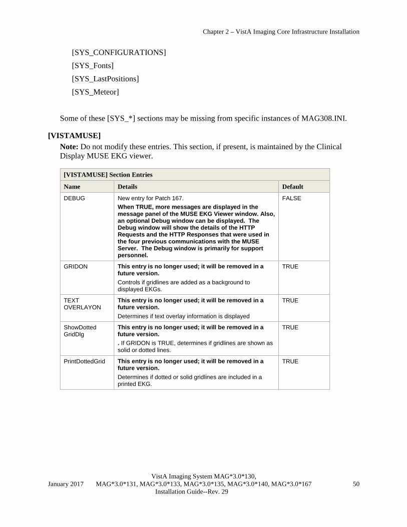
Chapter 2 – VistA Imaging Core Infrastructure Installation
VistA Imaging System MAG*3.0*130, January 2017 MAG*3.0*131, MAG*3.0*133, MAG*3.0*135, MAG*3.0*140, MAG*3.0*167 50 Installation Guide--Rev. 29
[SYS_CONFIGURATIONS]
[SYS_Fonts]
[SYS_LastPositions]
[SYS_Meteor]
Some of these [SYS_*] sections may be missing from specific instances of MAG308.INI.
[VISTAMUSE] Note: Do not modify these entries. This section, if present, is maintained by the Clinical Display MUSE EKG viewer.
[VISTAMUSE] Section Entries
Name Details Default
DEBUG New entry for Patch 167. When TRUE, more messages are displayed in the message panel of the MUSE EKG Viewer window. Also, an optional Debug window can be displayed. The Debug window will show the details of the HTTP Requests and the HTTP Responses that were used in the four previous communications with the MUSE Server. The Debug window is primarily for support personnel.
FALSE
GRIDON This entry is no longer used; it will be removed in a future version. Controls if gridlines are added as a background to displayed EKGs.
TRUE
TEXT OVERLAYON
This entry is no longer used; it will be removed in a future version. Determines if text overlay information is displayed
TRUE
ShowDotted GridDlg
This entry is no longer used; it will be removed in a future version. . If GRIDON is TRUE, determines if gridlines are shown as solid or dotted lines.
TRUE
PrintDottedGrid This entry is no longer used; it will be removed in a future version. Determines if dotted or solid gridlines are included in a printed EKG.
TRUE

Chapter 2 – VistA Imaging Core Infrastructure Installation
VistA Imaging System MAG*3.0*130, January 2017 MAG*3.0*131, MAG*3.0*133, MAG*3.0*135, MAG*3.0*140, MAG*3.0*167 51 Installation Guide--Rev. 29
[VISTAMUSE] Section Entries
Name Details Default
SiteNumber This entry is no longer used; it will be removed in a future version. When set to 0, the workstation will use the MUSE Site Number stored in the Imaging Site Parameters File (#2006.1). If an individual workstation must use a site number other than the one stored in #2006.1, this value can be changed as directed by Customer Support. Background - MUSE site numbers are assigned to each facility that uses the EKG database. Where multiple facilities use the same database, more than one site number will be present. Each site number is stored in a separate folder on the MUSE Server under the VOL000 share. Folders are given names starting with 'Site', i.e. Site01, Site02, Site03...
0
[Workstation Settings] This section contains workstation settings that relate to various areas of the Imaging System. In most cases, entries in this section do not need to be changed.
• For Display workstations that are connecting to a MUSE server, the ‘MUSE Enabled’ entry should be set to TRUE.
• For certain Capture workstations, the ‘Workstation TimeOut Minutes’ entry may need to be set.
[Workstation Settings] Section Entries
Name Details Default
ID Obsolete. Retained for backward compatibility. Unique workstation ID (IAD) used in the Imaging Access Log File (#2006.95)
UNKnown
Location A free text field identifying the location of the workstation. UNKnown
Abstracts created
When TRUE, image abstracts (.abs files) will be created by the workstation. When FALSE, abstracts will be created by the Imaging Background Processor workstation. A setting of TRUE is recommended.
TRUE
Save Radiology BIG file
Reserved for future use. FALSE
Display Jukebox Abstracts
N/A Entry will be removed in a later version. Tier 2 abstracts are no longer displayed in Clinical Display.
FALSE
Log Session Actions
Reserved for future use. FALSE
VistaRad test mode
N/A Entry will be removed in a later version. FALSE
MUSE Enabled Set to TRUE to enable the display of EKGs images for sites running the GE/Marquette MUSE interface.
FALSE

Chapter 2 – VistA Imaging Core Infrastructure Installation
VistA Imaging System MAG*3.0*130, January 2017 MAG*3.0*131, MAG*3.0*133, MAG*3.0*135, MAG*3.0*140, MAG*3.0*167 52 Installation Guide--Rev. 29
[Workstation Settings] Section Entries
Name Details Default
MUSE Demo Mode
Not for general use. This setting is for demonstrations given by the Imaging Implementation team. This should always be set to FALSE.
FALSE
Allow Image SaveAs
Not for general use. Allows demo images to be saved to the local hard drive.
FALSE
Allow Fake Name
Not for general use. If true, ‘Buzz,Lightyear’ is substituted for patient name
WARNING: Does not affect ‘burned in’ information embedded in an image.
FALSE
Workstation Timeout Minutes
When set to 0, all Imaging applications on the workstation use the application timeout value stored in the Imaging Site Parameters File (#2006.1) When set to a value other than 0, the workstation uses this value as a timeout parameter instead of the value stored in (#2006.1).
Note: This entry can be used for Capture workstations involved in lengthy procedures.
0
[Remote Site Options] This section contains workstation settings used for remote image view access in the Imaging system. Entries in this section should not be changed unless directed by Imaging Support.
[Remote Site Options] Section Entries
Name Details Default
RemoteImageViewsEnabled
Allows enabling and disabling of remote image views for the individual client machine. This might be useful if an individual client would not want to view remote images.
TRUE
2.5.8 Testing Imaging System Function To test the VistA Imaging System function, follow these steps:
1. Set up a test patient with at least one…
• Radiology procedure • Laboratory specimen • Surgery operation • Medical procedure (optional) • Progress Note • Clinical Procedure • TeleReader Consult
2. Follow the instructions below to test each specialty package. The VistA Imaging System User Manual or online help contains more detailed instructions on use of the software.

Chapter 2 – VistA Imaging Core Infrastructure Installation
VistA Imaging System MAG*3.0*130, January 2017 MAG*3.0*131, MAG*3.0*133, MAG*3.0*135, MAG*3.0*140, MAG*3.0*167 53 Installation Guide--Rev. 29
2.5.8.1 Testing Medicine Package Interface To test the Medicine Package Interface, follow these steps:
1. Launch the capture application.
2. Select the ‘Configurations|Configuration Settings|All Settings…’ menu. Select the Medicine VistA Package. Option to capture an image for your test patient. Your test patient must be entered as a “medical patient” in the Medicine package first.
3. Click on the “Select Medicine Procedure” button and select an existing procedure for your test or click the New button to create a “stub” procedure in the Medicine package.
4. You can perform this test with or without a video-input device; if you do not have a video device, use the "Import" option.
5. Enter a description that contains the word TEST so you can identify the image.
6. Select a Doc/Image Type from the drop down list, and optionally a specialty and Proc/Event.
7. Save the image by clicking on the “Capture” button, and then on the “Image OK” button.
8. Click on the “study complete” button.
9. Use the Display Window and select the test patient. You should see the abstract for the image you just captured. You should be able to select this abstract and you will see the group window with one abstract.
10. Click on this abstract and the captured image should be displayed in full resolution. Clicking on the report button should display the report header information.
11. Verify that it is the image you just captured and that the quality is good.
2.5.8.2 Testing Radiology Package Interface To test the Radiology Package Interface, follow these steps:
1. If your site is using the Radiology package for image capture, open the VistA Imaging Capture program to capture an image for the test patient.
2. Select the ‘Configurations|Configuration Settings|All Settings…’menu. Select Radiology as the VistA Package.
3. You will need to set up a case number for the test patient; use the Radiology ordering process to do this. You may need assistance from someone who knows the radiology ordering and reporting process in detail.
4. Click on the “Select Radiology Exam” button and select a radiology exam for your test.
5. Select a Doc/Image Type from the drop down list, and optionally a specialty and Proc/Event.
6. If you are using a scanner to capture an image, it must be properly set up for testing. You should also test using the other input types. In the case of Import, you do not need to have the capture device attached to the system. Image files are selected from a local drive.
7. View the image and report as described above.

Chapter 2 – VistA Imaging Core Infrastructure Installation
VistA Imaging System MAG*3.0*130, January 2017 MAG*3.0*131, MAG*3.0*133, MAG*3.0*135, MAG*3.0*140, MAG*3.0*167 54 Installation Guide--Rev. 29
2.5.8.3 Testing Anatomic Pathology Interface To test the Anatomic Pathology Package Interface, follow these steps:
1. Open the Imaging Capture program to capture an image for the test patient.
2. Select Options|Configuration.
a. Select the ‘Configurations|Configuration Settings|All Settings…’menu. Select Laboratory as the Specialty.
Note: Prior to capturing, the test patient must have a Laboratory accession number. You will need to use the Laboratory package AP menu option on the VistA HIS to create the accession number for the test patient. If you are unfamiliar with these options, ask for assistance from someone who knows the anatomic pathology ordering and processing steps.
b. Click on the “Select Laboratory Specimen” button and select a specimen for your test.
c. To capture images under the Laboratory specialty, you will also need to specify the… Laboratory sub-specialty (i.e., Surgical Pathology, Cytology, Electron Microscopy, etc.) accession year and accession number.
3. Once this is provided, a window with a list of specimens will display and you must select the specimen that pertains to the image.
4. Select a Doc/Image Type from the drop down list, and optionally a specialty and Proc/Event.
5. Capture an image from the camera, scanner, or import input source.
6. View the image as described above using the VistA Imaging System display options.
7. Verify that the captured image displays correctly both as an abstract and as a full image.
8. View the reports.
2.5.8.4 Testing Surgery Package Interface To test the Surgery Package Interface, follow these steps:
1. Open the VistA Imaging Capture program to capture an image for the test patient.
Note: The test patient must have an operation in the system prior to capturing. 2. Select the ‘Configurations|Configuration Settings|All Settings…’menu.
3. Select Surgery as the VistA Package.
4. Click on the “Select Surgery Case” button. A surgery case list will be displayed. Select the case for your test.
5. Select a Doc/Image Type from the drop down list, and optionally a specialty and Proc/Event.
6. Capture an image from the camera, scanner, or import input source.
7. View the image as described above using the VistA Imaging System display options.
8. Verify that the captured image displays correctly both as an abstract and as a full image. You should be able to see the surgery report when you click on the report button.

Chapter 2 – VistA Imaging Core Infrastructure Installation
VistA Imaging System MAG*3.0*130, January 2017 MAG*3.0*131, MAG*3.0*133, MAG*3.0*135, MAG*3.0*140, MAG*3.0*167 55 Installation Guide--Rev. 29
2.5.8.5 Testing Progress Notes Package Interface To test the Progress Notes Package Interface, follow these steps:
1. Open the VistA Imaging Capture program to capture an image for the test patient.
Note: The test patient must have a Progress Note in the system prior to capturing. 2. Select the ‘Configurations|Configuration Settings|All Settings…’menu.
3. Select Progress Notes as the VistA Package.
4. Click on the “Select Progress Note” button. A progress note list will be displayed. Select the note for your test.
5. Select a Doc/Image Type from the drop down list, and optionally a specialty and Proc/Event.
6. Capture an image from the camera, scanner, or import input source.
7. View the image as described above using the VistA Imaging System display options.
8. Verify that the captured image displays correctly both as an abstract and as a full image. You should be able to see the progress note when you click on the report button.
2.5.8.6 Testing Clinical Procedures Interface To test the Clinical Procedures Package Interface, follow these steps:
1. Open the VistA Imaging Capture program to capture an image for the test patient.
Note: The test patient must have a Clinical Procedure in the system prior to capturing. 2. Select the ‘Configurations|Configuration Settings|All Settings…’menu.
3. Select Clinical Procedures as the VistA Package.
4. Click on the “Select Clinical Procedure” button. A Clinical Procedure list will be displayed. Select an entry for your test.
5. Select a Doc/Image Type from the drop down list, and optionally a specialty and Proc/Event.
6. Capture an image from the camera, scanner, or import input source.
7. View the image as described above using the VistA Imaging System display options.
8. Verify that the captured image displays correctly both as an abstract and as a full image. You should be able to see the clinical procedure note when you click on the report button.
2.5.8.7 Testing Clinical Image Capture 1. To test the Patient Only Clinical Image capture, follow these steps:
2. Open the VistA Imaging Capture program to capture an image for the test patient.
3. Select the ‘Configurations|Configuration Settings|All Settings…’menu.
4. Select Clinical as the Patient Only Association
5. Select a Doc/Image Type from the drop down list, and optionally a specialty and Proc/Event.
6. Capture an image from the camera, scanner, or import input source.

Chapter 2 – VistA Imaging Core Infrastructure Installation
VistA Imaging System MAG*3.0*130, January 2017 MAG*3.0*131, MAG*3.0*133, MAG*3.0*135, MAG*3.0*140, MAG*3.0*167 56 Installation Guide--Rev. 29
7. View the image as described above using the VistA Imaging System display options.
8. Verify that the captured image displays correctly both as an abstract and as a full image.
2.5.8.8 Testing Administrative Image Capture Note : You may need to be assigned the Imaging Capture key for Administrative capture and
Display before proceeding. 1. To test the Patient Only Clinical Image capture, follow these steps:
2. Open the VistA Imaging Capture program to capture an image for the test patient.
3. Select the ‘Configurations|Configuration Settings|All Settings…’menu.
4. Select Administrative as the Patient Only Association.
5. Select a Doc/Image Type from the drop down list.
6. Capture an image from the camera, scanner, or import input source.
7. View the image as described above using the VistA Imaging System display options.
8. Verify that the captured image displays correctly both as an abstract and as a full image.
2.5.8.9 Testing Photo ID Capture To test the Patient Only Photo ID capture, follow these steps:
1. Open the VistA Imaging Capture program to capture an image for the test patient.
2. Select the ‘Configurations|Configuration Settings|All Settings…’menu.
3. Select Photo ID as the Patient Only Association
Note: Image Desc and Study Performed will have values of ‘PHOTO ID’ and Photo ID Date will have today’s date as the value.
4. Capture an image from the camera, scanner, or import input source.
5. View the image as described above using the VistA Imaging System display options.
6. Verify that the captured image displays correctly in the Patient Photo area.
2.5.8.10 Testing the TeleReader Consult Interface To test the TeleReader Consult Interface, follow these steps:
1. Open the Imaging Capture program to capture an image for the test patient.
2. Select the Configurations|Configuration Settings|All Settings menu.
3. Select TeleReader Consult as the Association.
Note: The test patient must have a consult in the system prior to capturing. The consult must be configured for the TeleReader.
4. In Capture, click Select TeleReader Consult. A TeleReader Consult list will be displayed.

Chapter 2 – VistA Imaging Core Infrastructure Installation
VistA Imaging System MAG*3.0*130, January 2017 MAG*3.0*131, MAG*3.0*133, MAG*3.0*135, MAG*3.0*140, MAG*3.0*167 57 Installation Guide--Rev. 29
5. Select the consult for your test.
6. Select a Doc/Image Type from the drop-down list, and optionally a specialty and Proc/Event.
7. Capture an image from the camera, scanner, or import input source.
8. Complete header information, e.g. body part and laterality.
9. View the image as described above using the VistA Imaging System display options.
10. Verify that the captured image displays correctly both as an abstract and as a full image.
2.6 Installing Optional Components
2.6.1 MUSE EKG Interface VistA Imaging can be interfaced with the GE MUSE EKG Management system. When this interface is configured, EKGs are viewable from any VistA Imaging Clinical workstation at the medical center.
• EKG waveforms and reports are retrieved directly from the MUSE server on demand. (VistA Imaging does not duplicate the storage of EKG data on the Imaging file servers.)
• Confirmed and unconfirmed EKGs are available for viewing. There are clear indicators on the report that show when an EKG report is unconfirmed.
• Users can view and manipulate multiple EKG reports simultaneously. Sites can configure the VistA Imaging software to view EKGs from multiple MUSE servers and multiple MUSE sites. There are different MUSE server configurations across the VA:
• Some VISNs share a single MUSE server that has multiple MUSE patient databases defined for each hospital. These separate patient databases are called “MUSE sites”.
• Some VISNs have a single MUSE server with one (merged) MUSE site that serves multiple hospitals.
• Another variation is to have a separate MUSE server at each hospital with a single MUSE site configured for each local hospital.
Note: When a MUSE server is installed, VHAxxxMUS1 (where xxx is the three-character site code) should be used as the MUSE server name.
Add VA Facility Subnet to MUSE ACL to Allow Communication on Port 8100 To ensure that all the proper ports are open and that the MUSEAPI service is running, users may have to add their VA facility subnet to the MUSE ACL.
1. Log on to the MUSE server and open services.msc. Verify that the MUSEAPI3 service is installed and running. If the MUSEAPI3 service is not installed GE can assist the MUSE POC.

Chapter 2 – VistA Imaging Core Infrastructure Installation
VistA Imaging System MAG*3.0*130, January 2017 MAG*3.0*131, MAG*3.0*133, MAG*3.0*135, MAG*3.0*140, MAG*3.0*167 58 Installation Guide--Rev. 29
2. Log on to the MUSE server and open a cmd prompt and run netstat –a. One of the returned entries should show 8100 in the local address list with the state “Listening”.
3. Submit a ticket to have the MUSE ACL modified to allow all 10.xxx.xxx.xxx (i.e., 10.152.0.0 0.0.255.255) traffic on port 8100. Each site will have to have their subnet added to the MUSE ACL.
Add VistA Imaging Service Account to MUSE This new interface does not require or use the share. The user credentials being passed into MUSEAPI3 need to have a matching MUSE user account.
• This is the account which is designated in your BP Queue Processor > Network Location Manager > EKG >User Name column, typically the VistA Imaging IU service account would be used (i.e., VHAxx\VHAxxxIU).
• The password used within MUSE must match the service account password. For more information, please see the MUSE™ v9 Cardiology Information System Operator's Manual 2059568-009. Page 158 (under system settings section) has a sub-section on adding users to MUSE.
2.6.1.1 Interfacing VistA Imaging with the MUSE System These procedures are intended for MUSE v8 SP2 or higher. Earlier versions of MUSE are no longer supported.
1. On each Imaging workstation that will be displaying EKGs, use the MAGSYS tool to set MUSE Enabled=TRUE in the Workstation Settings section of the MAG.INI file (for more information, see section 2.5.7 Edit the Imaging Workstation Configuration File with the MAGSYS Tool).

Chapter 2 – VistA Imaging Core Infrastructure Installation
VistA Imaging System MAG*3.0*130, January 2017 MAG*3.0*131, MAG*3.0*133, MAG*3.0*135, MAG*3.0*140, MAG*3.0*167 59 Installation Guide--Rev. 29
2. At the VA site that will be retrieving EKGs, use the Background Processor to add network
locations for each MUSE site (MUSE patient database on a MUSE server) being connected to.. If you are upgrading a MUSE to version 8 SP2 (or higher), you do not need to add a new entry to the Network Location file. You can modify the existing MUSE entry.
• Use the Background Processor’s Edit | Network Location Manager menu option to add or edit Network Location entries (for more information, see section 2.4.5.1, Edit the NETWORK LOCATION File (#2005.2)).
• The following example shows network locations for a MUSE server at a fictitious site.
Note: Use the local site’s IU account for the USER NAME (i.e.: VHAxx\VHAxxIU) for all remote locations – the local site is the site that is configuring remote locations. XXX is the local site in the example above, so that site’s IU account is for both MUSE servers, even though one of them is local and the other one is remote.
2.6.1.2 MUSE Error Codes Starting with Clinical Display 167, the Display Client uses the MUSE API 3 to interface with the MUSE Server. Data is transmitted from the client by sending HTTP XML requests. The client receives HTTP XML responses to the requests.
Error codes in the response are standard HTTP error codes (e.g., 401-Unauthorized).

Chapter 2 – VistA Imaging Core Infrastructure Installation
VistA Imaging System MAG*3.0*130, January 2017 MAG*3.0*131, MAG*3.0*133, MAG*3.0*135, MAG*3.0*140, MAG*3.0*167 60 Installation Guide--Rev. 29
The list of error code is not contained in this document. The complete list of HTTP error codes can be found on various web pages. One such web page is on Wikipedia: https://en.wikipedia.org/wiki/List_of_HTTP_status_codes
2.6.2 Associating Display and Capture with CPRS The CPRS GUI Tools menu can be configured to include options to launch VistA Imaging Display or Capture. When Display or Capture is launched from CPRS, any newly-selected patients in CPRS will also be selected in Display or Capture.
• If CCOW is implemented, patient synchronization is two-way (selecting a patient in Display/Capture will update CPRS, and vice-versa).
• If CCOW is not implemented, the synchronization is one way (patients must be selected in CPRS; patient selection will be disabled in Display/Capture while CPRS is active).
Also, when Imaging Display is active, selecting a CPRS report with an associated image or scanned document will automatically open the image or scanned document in Display. In CPRS, an image indicator is shown next to reports (such as Radiology reports or TIU documents) that have associated images or scanned documents.
Note: The VistA Imaging TeleReader application should not be put into the CPRS Tools menu. TeleReader is designed to work as a standalone application and should not be launched from CPRS.
2.6.2.1 Initial Setup To set up the CPRS GUI – VistA Imaging association, perform the following steps. Note that these steps will affect all CPRS GUI applications. (These are summary steps only; please review the CPRS Technical Manual for detailed information.)
1. Access the CPRS GUI Tools Menu [ORWT TOOLS MENU] on the VistA system. This can be done by running XPAREDIT routine, or by using CPRS Manager Menu [ORMGR] as shown below.
Select OPTION NAME: ORMGR CPRS Manager Menu CL Clinician Menu ... NM Nurse Menu ... WC Ward Clerk Menu ... PE CPRS Configuration (Clin Coord) ... IR CPRS Configuration (IRM) ... Select CPRS Manager Menu Option: IR CPRS Configuration (IRM) OC Order Check Expert System Main Menu ... TI ORMTIME Main Menu ... UT CPRS Clean-up Utilities ... XX General Parameter Tools ... Select CPRS Configuration (IRM) Option: XX General Parameter Tools LV List Values for a Selected Parameter LE List Values for a Selected Entity LP List Values for a Selected Package LT List Values for a Selected Template EP Edit Parameter Values

Chapter 2 – VistA Imaging Core Infrastructure Installation
VistA Imaging System MAG*3.0*130, January 2017 MAG*3.0*131, MAG*3.0*133, MAG*3.0*135, MAG*3.0*140, MAG*3.0*167 61 Installation Guide--Rev. 29
ET Edit Parameter Values with Template Select General Parameter Tools Option: EP Edit Parameter Values --- Edit Parameter Values --- Select PARAMETER DEFINITION NAME: ORWT TOOLS MENU CPRS GUI Tools Menu
2. In the CPRS GUI Tools Menu, select the System option. Usually this is the 4th option.
ORWT TOOLS MENU may be set for the following: 1 User USR [choose from NEW PERSON] 2 Location LOC [choose from HOSPITAL LOCATION] 2.5 Service SRV [choose from SERVICE/SECTION] 3 Division DIV [choose from INSTITUTION] 4 System SYS [IMGDEM01.MED.VA.GOV] 9 Package PKG [ORDER ENTRY/RESULTS REPORTING] Enter selection: 4 System IMGDEM01.MED.VA.GOV
3. Enter ? at the Select Sequence prompt to determine which sequence numbers have already been defined.
---------- Setting ORWT TOOLS MENU for System: IMGDEM01.MED.VA.GOV ---------- Select Sequence: ? Sequence Value -------- ----- 1 Dental Record Manager Plus=C:\DOCSTORE\dentalmrmtx.exe s=%SRV p=%PORT 2 BCMA="c:\program files\vista\bcma\bcma.exe" %DFN %MREF %SRV %PORT 3 BCMAPAR="c:\program files\vista\bcma\bcmapar.exe" %DFN %MREF %SRV %PO
4. Enter the new number at the Select Sequence prompt, press Enter when asked for confirmation, and then re-enter the new number to select it for editing.
Select Sequence: 5 Are you adding 5 as a new Sequence? Yes// <enter> YES ---------- Setting ORWT TOOLS MENU for System: IMGDEM01.MED.VA.GOV ---------- Select Sequence: 5
5. To set up a CPRS- Imaging Display association, enter the text exactly as shown below at the prompt.
Name=Command:VistA Imaging Display=MagImageDisplay.exe %DFN %MREF %SRV %PORT
Note: Be sure to enter the text as a single line (do not press <Enter> until the full command has been typed in).

Chapter 2 – VistA Imaging Core Infrastructure Installation
VistA Imaging System MAG*3.0*130, January 2017 MAG*3.0*131, MAG*3.0*133, MAG*3.0*135, MAG*3.0*140, MAG*3.0*167 62 Installation Guide--Rev. 29
6. To set up a similar association for VistA Imaging Capture, define a new sequence as described in step 4, and then enter the text exactly as shown below at the prompt.
Name=Command:VistA Imaging Capture=MagImageCapture.exe %DFN %MREF %SRV %PORT
Note: Be sure to enter the text as a single line (do not press <Enter> until the full command has been typed in).
7. Start the CPRS GUI and verify that Display and Capture are listed as options under the Tools menu, and that they can be started from CPRS.
8. After starting Display and/or Capture, select a different patient in CPRS, and verify that Display and/or Capture update to reflect the newly selected patient.
a. If the step above fails, verify that the parameters entered in steps 5 and 6 were entered correctly.
b. If the initial patient synchronization between CPRS and Display or Capture works, but fails for subsequently selected patients, check that CCOW is functioning properly (if CCOW is implemented at your site) or (if CCOW is not implemented) verify that Windows messaging is enabled by checking the ORWOR BROADCAST MESSAGES CPRS Parameter.

Chapter 2 – VistA Imaging Core Infrastructure Installation
VistA Imaging System MAG*3.0*130, January 2017 MAG*3.0*131, MAG*3.0*133, MAG*3.0*135, MAG*3.0*140, MAG*3.0*167 63 Installation Guide--Rev. 29
2.6.2.2 Modifying Tools Menu Settings for VistA Imaging Display and Capture After installing MAG*3.0*122 or a subsequent patch on all workstations, you should change the settings of the CPRS Tools menu used to launch VistA Imaging Clinical Display and VistA Imaging Clinical Capture. This is necessary because the applications are installed in different folders depending on whether they are installed on a computer with a 32-bit operating system or on a computer with a 64-bit operating system.
The paths in which VistA Imaging Clinical Display and VistA Imaging Clinical Capture are installed are:
Installation Directory Operating System
c:\program files\vista\imaging 32-bit
c:\program files (x86)\vista\imaging\ 64-bit
The MAG*3.0*122 installation adds the path in which VistA Imaging Clinical Display and VistA Imaging Clinical Capture are installed to the Windows system path and you can remove it from the configuration of the CPRS Tools menu.
If any workstations at your site are running versions of VistA Imaging Clinical Display and VistA Imaging Clinical Capture earlier than MAG*3.0*122, such as MAG*3.0*117, you should add the paths in which the Clinical Display and Clinical Capture are installed to the system path on these workstations. You can do this centrally using a tool like Active Directory Group Policy Objects (GPO).
This section provides the steps you need to perform once for the entire site after installing MAG*3.0*122 or a subsequent patch on all workstations.
To change the CPRS Tools menu settings used to launch VistA Imaging Display or Capture:
1. Access the CPRS GUI Tools Menu [ORWT TOOLS MENU] on the VistA system and check the current settings for VistA Imaging Display and Capture by performing steps 1 – 5 in section 2.6.2.1 Initial Setup.
2. Enter the new number of the sequence you want to edit at the Select Sequence prompt, press Enter when asked for confirmation, and then re-enter the new number to select it for editing.
The following is an example of the output. The selections and user input are bolded. Select OPTION NAME: ORW TOOL MENU ITEMS GUI Tool Menu Items CPRS GUI Tools Menu may be set for the following: 1 User USR [choose from NEW PERSON] 2 Location LOC [choose from HOSPITAL LOCATION] 2.5 Service SRV [choose from SERVICE/SECTION] 3 Division DIV [choose from INSTITUTION] 4 System SYS [IMGDEM01.MED.VA.GOV] Enter selection: 4 System IMGDEM01.MED.VA.GOV ---------- Setting ORWT TOOLS MENU for System: IMGDEM01.MED.VA.GOV ----------

Chapter 2 – VistA Imaging Core Infrastructure Installation
VistA Imaging System MAG*3.0*130, January 2017 MAG*3.0*131, MAG*3.0*133, MAG*3.0*135, MAG*3.0*140, MAG*3.0*167 64 Installation Guide--Rev. 29
Select Sequence: ? Sequence Value -------- ----- 3 VistA Imaging Display=c:\program files\vista\imaging\MagImageDisplay 4 VistA Imaging Capture=c:\program files\vista\imaging\MagImageCapture 5 Dental Record Manager Plus=C:\DOCSTORE\dentalmrmtx.exe s=%SRV p=%PORT 10 BCMA="c:\program files\vista\bcma\bcma.exe" %DFN %MREF %SRV %PORT 15 BCMAPAR="c:\program files\vista\bcma\bcmapar.exe" %DFN %MREF %SRV %PO Select Sequence: 3// 3
3. At the Replace prompt, enter the value with the association for VistA Imaging Display and press Enter. Then, at the With prompt, enter what the modified value should be.
The following example shows how to replace c:\program files\vista\imaging\MagImageDisplay.exe with MagImageDisplay.exe
Name=Command: VistA Imaging Display=c:\program files\vista\imaging\MagImageDisplay.exe %DFN %MREF %SRV %PORT Replace c:\program files\vista\imaging\MagImageDisplay.exe With MagImageDisplay.exe Replace <CR> VistA Imaging Display=MagImageDisplay.exe %DFN %MREF %SRV %PORT
Note: Be sure to enter the text as a single line (do not press <Enter> until the full command has been typed in).
4. Enter the value with the association for VistA Imaging Capture and press Enter. Then, at the With prompt, enter what the modified value should be.
The following example shows how to select the sequence 4 and how to replace c:\program files\vista\imaging\MagImageCapture.exe with MagImageCapture.exe
Sequence: 4// 4 Name=Command: VistA Imaging Capture=c:\program files\vista\imaging\MagImageCapture.exe %DFN %MREF %SRV %PORT Replace c:\program files\vista\imaging\MagImageCapture.exe With MagImageCapture.exe Replace <CR> VistA Imaging Capture=MagImageCapture.exe %DFN %MREF %SRV %PORT
Note: Be sure to enter the text as a single line (do not press <Enter> until the full command has been typed in).
5. Verify that the changes in the associations are accurate by typing ? at the Select Sequence prompt, as illustrated in the following example. Select Sequence: ? Sequence Value -------- ----- 3 VistA Imaging Display=MagImageDisplay.exe %DFN %MREF %SRV %PORT 4 VistA Imaging Capture=MagImageCapture.exe %DFN %MREF %SRV %PORT 5 Dental Record Manager Plus=C:\DOCSTORE\dentalmrmtx.exe s=%SRV p=%PORT 10 BCMA="c:\program files\vista\bcma\bcma.exe" %DFN %MREF %SRV %PORT 15 BCMAPAR="c:\program files\vista\bcma\bcmapar.exe" %DFN %MREF %SRV %PO

Chapter 2 – VistA Imaging Core Infrastructure Installation
VistA Imaging System MAG*3.0*130, January 2017 MAG*3.0*131, MAG*3.0*133, MAG*3.0*135, MAG*3.0*140, MAG*3.0*167 65 Installation Guide--Rev. 29
6. On each workstation, add the paths in which the VistA Imaging Display and Capture are installed to the system menu.
7. Start the CPRS GUI and verify that VistA Imaging Display and Capture are listed as options under the Tools menu, and that they can be started from CPRS.
2.6.3 Configuring VistA Imaging to Process a GCC A protocol must be configured in the Image Actions file in order to establish a local GCC task. A Photo-ID protocol is an example of one that is in the VistA Imaging distribution. Similar post capture protocols can be set up by the site.
1. Use the Background Processor to create a new network location. 2. On the client server, on the main Queue Processor window, select Edit | Network Location
Manager. 3. On the Network Location Manager window, select the GCC tab and click New. 4. Enter the following information:
• Share Name - provide a short identification (such as GCCn where n is a number). • Network Path - provide the full directory path to a remote shared directory. This field
uses the Universal Naming Convention (UNC) file share name. • Storage Type should be GCC.
5. Press <tab> and click Apply. The Storage Type will be EXPORT. The additional parameters will be available
• Operational Status • Hashed Dir Structure • User Name • Password
8
Note: The user can specify connection credentials that the BP Queue Processor will use when the share is not mapped.
6. Set the GCC default location--on the BP, select Edit |Imaging Site Parameters. 7. Set the Current GCC location to the newly created Network Location in the Administrative
settings section.

Chapter 2 – VistA Imaging Core Infrastructure Installation
VistA Imaging System MAG*3.0*130, January 2017 MAG*3.0*131, MAG*3.0*133, MAG*3.0*135, MAG*3.0*140, MAG*3.0*167 66 Installation Guide--Rev. 29
2.6.3.1 GCC Queue for PhotoID The GCC has a method for exporting photo IDs to a designated share as a post-capture process. Its implementation requires an entry in the IMAGE ACTIONS file (#2005.86). Its purpose is to export the files to a site specified print server or share either within the local area network or external to the local area network.
This protocol was requested by Indian Health Service (IHS) and called for the exported file to have the patient’s DFN included in the file name so that the operator could correctly assign a patient photo IDs.
In order to activate this functionality, create one or more GCC locations to receive the exported photo IDs using Network Location Manager. Edit the protocol in the IMAGE ACTIONS file (#2005.86) using FileMan.
Example: VA FileMan 2<.0 Select OPTION: ENTER OR EDIT FILE ENTRIES INPUT TO WHAT FILE: 2005.86 IMAGE ACTIONS (2 entries) EDIT WHICH FIELD: ALL// ACTIVE THEN EDIT FIELD: TAG THEN EDIT FIELD: ROUTINE THEN EDIT FIELD: TYPE (multiple) EDIT WHICH TYPE SUB-FIELD: ALL//<enter> THEN EDIT FIELD: EXPORT LOCATION THEN EDIT FIELD: <enter> STORE THESE FIELDS IN TEMPLATE: <enter> Select IMAGE ACTIONS NAME: PHOTO-ID COPY ACTIVE: NO// Y YES TAG: PID//<enter> ** ROUTINE: MAGQBGCC//<enter>** Select TYPE: PHOTO ID//< enter> EXPORT LOCATION: GCC21 <<<this field points to the NETWORK LOCATION (#2005.2) file, select the network location to receive the exported image file. **the TAG and ROUTINE fields are predefined by VistA Imaging patch MAG*3.0*39 with the routine to be used by the HIS. The files created at the exported location will be named using the patient DFN. If a site wishes to change this, they can use a locally defined routine.
2.6.4 Diagram Annotation Tool Interface The Diagram Annotation tool is an optional Imaging component that is accessed from CPRS. The Diagram Annotation tool is used to annotate online diagram ‘templates’ and then save the results directly to a patient’s electronic medical record.
No separate installation is needed for the Diagram Annotation tool. It is present on any workstation where CPRS Chart and Clinical Imaging are installed. However, to enable the Diagram Annotation tool, configuration changes need to be made in CPRS Chart, the TIU package, and VistA Imaging.
Detailed information about enabling the Diagram Annotation tool is in the Diagram Annotation Tool User & Setup Guide. This document is available on the Imaging website at: http://vaww.va.gov/imaging/IMGmanualsRev3_0.htm.

Chapter 2 – VistA Imaging Core Infrastructure Installation
VistA Imaging System MAG*3.0*130, January 2017 MAG*3.0*131, MAG*3.0*133, MAG*3.0*135, MAG*3.0*140, MAG*3.0*167 67 Installation Guide--Rev. 29
2.6.5 TeleReader Interface The TeleReader application is an optional Imaging component that is accessed from the Windows Start menu. The TeleReader provides a work list for local or remote imaging studies that are waiting to be read and diagnosed by a qualified provider.
No separate installation is needed for the TeleReader application. It is present on any workstation where CPRS Chart and Clinical Imaging are installed. However, to enable the TeleReader application, configuration changes need to be made in VistA.
Detailed information about configuring the TeleReader application can be found in TeleReader Configuration document.
2.6.6 TeleReader Configurator Interface The TeleReader Configurator application provides a GUI-based interface to configure the TeleReader. The application gives the user extra direction, help and data validation while making changes to records within the VistA database.
The TeleReader Configurator is a Microsoft Windows-based GUI application. There are no additional business rules with the addition of this new interface.
Detailed information about the TeleReader Configurator interface can be found in the TeleReader Configurator User Guide document.
2.6.6.1 Installing TeleReader Configurator Note: The TeleReader Configurator is not meant for clinical users and should not be installed on clinical user workstations. It can be installed on any support staff workstation.
1 Copy the patch client distribution file to a local location, Typically, the patch client distribution file is a file with a name like MAG3_0P<PatchNumber>_TelereaderConfiguratorSetup.exe, where <PatchNumber> is the number of the patch.
2 Double-click the file to start the InstallShield Wizard.
3 After the Welcome dialog is displayed, click Next, then click Install. (There are no configurable installation options.) Installation typically takes less than 30 seconds.

Chapter 2 – VistA Imaging Core Infrastructure Installation
VistA Imaging System MAG*3.0*130, January 2017 MAG*3.0*131, MAG*3.0*133, MAG*3.0*135, MAG*3.0*140, MAG*3.0*167 68 Installation Guide--Rev. 29
4 When installation is finished, click Finish.
5 The Installation will place MagTeleReaderConfig.exe (the application) and MagTeleReaderConfig.pdf (the application help file) under C:\Program Files\VistA\Imaging (Windows XP 32-bit) and C:\Program Files (x86)\VistA\Imaging (Windows 7 64-bit). The application is also placed in the Start menu under VistA Imaging. Open the application. There will be a prompt for the server and port. Enter the appropriate values for the site’s local VistA RPC broker connection. Then enter Access and Verify codes when prompted and select the login. The main TeleReader Configurator screen will appear.
2.6.7 VistA Imaging AWIV The AWIV component is intended for use on workstations that have access to VistAWeb. When the AWIV is installed, VistAWeb users are able to display images associated with radiology reports and progress notes.
The AWIV is an Active X control that needs to be installed on the local workstation either manually or using an automated software distribution system. The AWIV presumes that VistAWeb V. 13 or later is installed on a central application server.
When the AWIV is installed,
• The software will be installed in C:\Program Files\Vista\Imaging\Lib on the local workstation.
• There are no configurable installation options.

Chapter 2 – VistA Imaging Core Infrastructure Installation
VistA Imaging System MAG*3.0*130, January 2017 MAG*3.0*131, MAG*3.0*133, MAG*3.0*135, MAG*3.0*140, MAG*3.0*167 69 Installation Guide--Rev. 29
When AWIV Web Application is used, workstations do not require access to VistAWeb or access to VistA Imaging Clinical Display. Images will be available in a Web-based interface, making it easier for users to access the images. Users can view images available in VistA Imaging and the DOD, including NCAT reports, and radiology images and artifacts stored in HAIMS using AWIV through Microsoft Internet Explorer (IE) 7, IE 8, or IE 9. For more information on using AWIV Web App, see the VistA Imaging AWIV Web Application Guide. When AWIV Web Application is used, workstations do not require access to VistAWeb or access to VistA Imaging Clinical Display. Images will be available in a Web-based interface, making it easier for users to access the images. Users can view images available in VistA Imaging and the DOD, including NCAT reports, and radiology images and artifacts stored in HAIMS using AWIV through Microsoft Internet Explorer (IE) 7, IE 8, or IE 9. For more information on using AWIV Web App, see the VistA Imaging AWIV Web Application Guide. Note: NCAT reports are available if NCAT is on line.
2.6.7.1 AWIV Install Prerequisites Workstations where the AWIV is installed must meet the following minimum requirements:
• Access to VistAWeb version 13 (WEBV*1*20) or later
• A VA-approved version of Microsoft Internet Explorer
• Display capability of 24-bit color with a screen resolution of 1024x768 pixels
• 1 gigabyte of RAM
Workstations using the AWIV Web Application must meet the following minimum requirements:
• Access to the CVIX
• MAG*3.0*124 KIDS is installed on the local VistA system
• Microsoft Internet Explorer 7, 8, or 9.
• Display capability of 24-bit color with a screen resolution of 1024x768 pixels
• 1 gigabyte of RAM
2.6.7.2 AWIV Automated Installation The AWIV installation file can be pushed to individual workstations using automated software distribution/inventory management tools. Specifics will vary, depending on the automated installation tool used.

Chapter 2 – VistA Imaging Core Infrastructure Installation
VistA Imaging System MAG*3.0*130, January 2017 MAG*3.0*131, MAG*3.0*133, MAG*3.0*135, MAG*3.0*140, MAG*3.0*167 70 Installation Guide--Rev. 29
2.6.7.3 AWIV Manual Installation To install the VistA Imaging AWIV software, follow these steps:
1. On the workstation where the AWIV will be installed, log in to an administrator-level account.
2. Double-click MagAWIVInstall.exe to start the installation wizard. There will be a brief delay as the installation files are extracted.
3. When the Welcome page appears, click Next.
4. When the Ready to Install page displays, click Install.
5. After installation is complete, click Finish to exit the wizard.
2.6.7.4 Verifying Installation To verify installation of the AWIV, view an image, either through VistAWeb or through the AWIV Web Application.
In MAG*3.0*122 and earlier patches, the Clinical Display, Clinical Capture, and TeleReader clients were distributed and installed together, with the same executable file, which was either an *.msi or an *.exe file with a name like:
• MAG3_0P122_Install.exe • MAG3_0P122_Install.msi
In subsequent patches, the Clinical Display, Clinical Capture, and TeleReader clients are not installed as a bundle. If the patch is a Clinical Display patch, for example, the patch will include only the Clinical Display client.
This change has impacted the steps required to revert to a previous version of the TeleReader client. To accomplish this, complete the following steps:
1. Uninstall MAG*3.0*127 VistA Imaging TeleReader 2. Uninstall MAG*3.0*122 3. Reinstall MAG*3.0*122.
2.7 Reverting to the MAG*3.0*122 Version of the Clinical Clients In MAG*3.0*122 and earlier patches, the Clinical Display, Clinical Capture, and TeleReader clients were distributed and installed together, with the same executable file, which was either an *.msi or an *.exe file with a name like:
• MAG3_0P122_Install.exe
• MAG3_0P122_Install.msi
In subsequent patches, the Clinical Display, Clinical Capture, and TeleReader clients are not installed as a bundle. If the patch is a Clinical Display patch, for example, the patch will include only the Clinical Display client.

Chapter 2 – VistA Imaging Core Infrastructure Installation
VistA Imaging System MAG*3.0*130, January 2017 MAG*3.0*131, MAG*3.0*133, MAG*3.0*135, MAG*3.0*140, MAG*3.0*167 71 Installation Guide--Rev. 29
This change has impacted the steps required to revert to a previous version of the clinical clients. The procedures to revert to the MAG*3.0*122 versions of the clients are described in subsequent sections.
2.7.1 Reverting to the MAG*3.0*122 TeleReader Client To revert to the MAG*3.0*122 TeleReader client:
1. Uninstall MAG*3.0*127 VistA Imaging TeleReader. 2. Uninstall MAG*3.0*122. 3. Reinstall MAG*3.0*122.
2.7.2 Reverting to the MAG*3.0*122 Clinical Display Client To revert the MAG*3.0*122 Clinical Capture client:
1. Uninstall the MAG*3.0*127 TeleReader client. 2. Uninstall the MAG*3.0*129 Clinical Capture client. 3. Uninstall the MAG*3.0*131 Clinical Display client 4. Uninstall the MAG*3.0*122 clinical workstation client. 5. Reinstall MAG*3.0*122 to return to the MAG*3.0*122 clinical workstation client, which
includes Clinical Capture, Clinical Display and TeleReader. 6. Reinstall MAG*3.0*127 to return to the patch 127 TelerReader client. 7. Reinstall MAG*3.0*129 to return to the patch 129 Clinical Capture client.
2.8 Reverting to a Previous Version of Client Software that is NOT MAG*3.0*122
This section explains how to revert to a previous version of the client software that is subsequent to MAG*3.0*122. If you want to revert to MAG*3.0*122, follow the steps in section Reverting to the MAG*3.0*122 Version of the Clinical Clients.
To revert to a previous version of Clinical Capture, Clinical Display or TeleReader client, uninstall the current version and reinstall the previous version of the client. Example
If after installing the MAG*3.0*140 Clinical Capture client, you want to revert to the MAG*3.0*129 Clinical Capture client, do the following:
1. Uninstall the MAG*3.0*140 Clinical Capture client. 2. Re-install the MAG*3.0*129 Clinical Capture client.
VistA Imaging System MAG*3.0*130, January 2017 MAG*3.0*131, MAG*3.0*133, MAG*3.0*135, MAG*3.0*140, MAG*3.0*167 72
Installation Guide--Rev. 29
Chapter 3 VistARad Installation 3.1 Introduction This chapter explains how to install and configure the VistARad workstation as a part of the VistA Imaging system. It contains the following information:
• VistARad workstation setup • VistARad host setup • Testing a VistARad installation
• Running VistARad in training mode The installation and setup of VistARad host (“back end”) and workstation (“client”) software is a multi-part process. This chapter assumes that the persons responsible for VistARad installation have a working knowledge of M(UMPS), VA FileMan, VistA Imaging, and Windows administration.
The Food and Drug Administration classifies VistARad as a medical device. As such, it may not be changed except as directed by the Vista Imaging HSD&D group. Modifications to this software may result in an adulterated medical device under 21CFR820, the use of which is considered to be a violation of US Federal Statutes.
3.2 VistARad Workstation Setup The following sections explain how to install and configure the VistARad client software on each diagnostic workstation. The following topics are covered:
• Workstation preparation • Configuration for high-resolution monitors • Workstation software installation • VistARad client software configuration
• High-resolution monitor maintenance
Note: The details of some aspects of workstation setup may vary depending on the version of the Microsoft Windows operating system and utilities. This document is updated to contain current information reflecting Windows 7 Professional, Service Pack 1.
3.2.1 Workstation Preparation For each workstation where VistARad client software will be installed:
• The minimum requirements for diagnostic workstation hardware and network connections must be met. Requirements are listed in the VistA Imaging Planning Document and Approved Equipment List; this document can be downloaded from the VistA Imaging SharePoint site at:
http://vaww.oed.portal.va.gov/applications/VistAImaging/default.aspx

Chapter 4 – Installing Image Acquisition Devices
VistA Imaging System MAG*3.0*130, January 2017 MAG*3.0*131, MAG*3.0*133, MAG*3.0*135, MAG*3.0*140, MAG*3.0*167 73 Installation Guide--Rev. 29
• The following software must be present: Microsoft Windows 7 Professional, Service Pack 1, or Microsoft Windows 7 Enterprise, Service Pack 1 Note: 64-bit versions of Windows 7 are preferred; 32-bit is acceptable Internet Explorer 8 or later Antivirus Software installed in accordance with site policy –note ePO exclusion below
Note: For security purposes, all disk partitions should be formatted using NTFS.
• The following software cannot be present:
Client software for Microsoft SMS (Systems Management Server) or SCCM (System Center Configuration Manager). See the next section for more information.
McAfee HIPs (Host Intrusion Prevention) or other third-party software firewalls.
McAfee ePolicy Orchestrator (ePO). Antivirus definitions and scanning engine updates should be configured in the antivirus client without the assistance of ePO.
Excluding VistARad from Software Pushes Because software distribution/inventory management tools can be used to install inappropriate or unapproved software without an administrator’s knowledge, VistARad workstations must be excluded from Microsoft’s Systems Management Server™ (SMS) server, SCCM, or similar systems.
Active Directory Group Policies Domain group policy is often used by domain and desktop administration staff to remotely configure operating system behavior and security on workstations within the enterprise. Many of these changes can have adverse effects on the performance and usability of VistARad workstations. VistARad workstations should be placed within an Active Directory Organizational Unit (OU), which is isolated from domain group policies intended for standard PCs. Any group policies applied to VistARad diagnostic workstations should be tested by VistA Imaging or PACS support staff before being put into clinical use.
Note: The installation of unapproved components onto a VistARad diagnostic workstation will result in an adulterated medical device. The use of adulterated medical devices violates US Federal Law (21CFR820).
For questions about the contents of these documents, refer to the EIE (Enterprise Infrastructure Engineering) portal at http://vaww.cis.va.gov/Pages/default.aspx.
3.2.1.1 Excluding VistARad from Software Pushes Because software distribution/inventory management tools can be used to install inappropriate or unapproved software without an administrator’s knowledge, VistARad workstations must be excluded from Microsoft’s Systems Management Server™ (SMS) server or similar systems.

Chapter 4 – Installing Image Acquisition Devices
VistA Imaging System MAG*3.0*130, January 2017 MAG*3.0*131, MAG*3.0*133, MAG*3.0*135, MAG*3.0*140, MAG*3.0*167 74 Installation Guide--Rev. 29
Note: The installation of unapproved components onto a VistARad diagnostic workstation will result in an adulterated medical device. The use of adulterated medical devices violates US Federal Law (21CFR820).
Information about exclusion and removal of SMS 2.0 and SMS 2003 can be found at http://vaww.va.gov/imaging/IMGFilmlessRad.htm. Additional information about SMS can be found at http://vaww.cis.va.gov/sites/SMS/EndUserInfo/WWWRoot/sms_documents.htm.
For questions about the contents of these documents, refer to the EIE (Enterprise Infrastructure Engineering) portal at http://vaww.cis.va.gov/Pages/default.aspx.
3.2.2 Configuration for High-Resolution Monitors This section covers:
• Driver setup guidelines • Display Settings—Workstation Specific • Display Settings—User Specific • Mouse settings
VistARad is capable of running on a wide array of workstation configurations from one to six monitors. A typical configuration used for diagnostic interpretation would include two high-resolution monitors for primary image display and a third “navigation” monitor to be used for the VistARad Manager window and other utility purposes (e.g., hosting a dictation client). The discussion below will use such a typical configuration for examples, but the principles covered are applicable to any configuration.
Once high-resolution monitors are set up and configured, a calibration and maintenance schedule will need to be established as described in Maintenance of High-Resolution Monitors.
3.2.2.1 Driver Setup Guidelines Display adapters/drivers produced by Barco, Image Systems, and NDSsi (Dome) have been tested and found operable for Windows 7-based VistARad workstations.
To configure the high-resolution display subsystems, follow vendor instructions for installing all associated hardware and configuring drivers. Make sure that all of the monitors are configured to run as “separate desktops.” This is essential for proper operation of VistARad on Windows workstations. Note that documentation and driver configuration dialogs for display adapters for different vendors may use different terminology to describe separate desktops (e.g., Barco uses the term “dual view” for this).
For grayscale displays, the preferred color palette mode setting should be 32-bit “color to gray” compatibility if available for the vendor’s product. If this is not available, then use a static gray palette (no system colors). Note that different manufacturers may use slightly different terminology for these settings.
Note: Some high-resolution monitors, such as the Barco Coronis Fusion (4MP, 6MP, and 10MP) line of displays, are designed to operate in a landscape orientation. While the device is a single

Chapter 4 – Installing Image Acquisition Devices
VistA Imaging System MAG*3.0*130, January 2017 MAG*3.0*131, MAG*3.0*133, MAG*3.0*135, MAG*3.0*140, MAG*3.0*167 75 Installation Guide--Rev. 29
screen, for best results when running VistARad, it is recommended that the driver be configured to operate as a dual-screen device. For example, the Barco Coronis Fusion 6MP should be configured as two 3MP screens.
After all driver installation steps are completed, make sure that the mouse cursor is visible on all monitors and that the cursor can be moved across all monitors in the expected order. Any screen “logical order” issues can be resolved following the steps in the next section.
3.2.2.2 Display Settings—Workstation Specific This section lists monitor settings and display properties changes that are required or recommended for all VistARad workstations using high-resolution displays. You will need administrative privileges on the workstation to perform some of these steps. You may need to reboot the computer for some of these settings to be applied.
Note: In most situations, the color quality and screen resolution settings tab should not be changed. These options are managed using the driver-specific settings that should be managed per the vendor’s documentation.
To simplify references to the functions to be used for the following configuration settings, the Control Panel home page is used for the starting point in each case. To facilitate this, use the “All Control Panel Items” listing of the Control panel:
• From the Start menu, select Control Panel.
• At the top-left of the navigation bar, select the Control Panel drop-down entry All Control Panel Items. This provides a convenient listing of all the Control Panel functions.
Note: various settings are described below as either recommended or required. If required, the setting is important for correct and/or best performance of VistARad, so should be configured as described. Recommended settings should be understood as providing a good starting point, but different settings may be used to accommodate individual user preferences.
• Select option: Control Panel | Display | Change display settings Note: the settings configured on this form are enforced for all users of the workstation.
This option presents a graphical representation of the entire multi-head desktop that indicates the logical relationship between the screens. Below are two screenshots annotated to draw your attention to several important elements—note that for some configurations, the monitor’s numeric sequence may not match the correct visual/logical sequence. This is not a problem, as long as the visual/logical sequence is correct.

Chapter 4 – Installing Image Acquisition Devices
VistA Imaging System MAG*3.0*130, January 2017 MAG*3.0*131, MAG*3.0*133, MAG*3.0*135, MAG*3.0*140, MAG*3.0*167 76 Installation Guide--Rev. 29
The currently selected monitor icon has a light-blue border.
• Click on the left-most high-resolution screen icon (labeled “3”, above); if the status line “This is currently your main display” does not appear, then select the check-box labeled “Make this my main display”.
• Click on each monitor icon in turn, and confirm that the Multiple displays drop-down value shows “Extend desktop to this display.” This is a required setting. If this is not the case, re-visit the driver installation and configuration procedure per the instructions above in Driver Setup Guidelines so that the displays operate as separate desktops.
• Make sure that all high-resolution screens are contiguous, and have the same horizontal alignment (required setting). If needed, drag the monitor icons so that all the top edges are aligned. For example, if you start to drag the main display icon, the top-left x-y coordinates value of “0,0” is displayed; dragging the other icons will show relative coordinates values—correct horizontal alignment can be confirmed by observing that the y-coordinate is zero (e.g., “2048,0”).
• For the optional navigation display (labeled 1 in the screenshot), it is recommended that the horizontal alignment line up with the top edge of the high resolution screens. If there is a consensus by users that a different alignment is preferred, there are no constraints by VistARad against that. However, for managing multiple workstations that share the same display configuration (i.e., the same number of same-sized monitors), it is strongly recommended that all of the workstations’ monitor alignment settings be configured the same way. This will ensure that as users work at different machines, their preferences for location and sizing of the various VistARad windows will not be compromised in any

Chapter 4 – Installing Image Acquisition Devices
VistA Imaging System MAG*3.0*130, January 2017 MAG*3.0*131, MAG*3.0*133, MAG*3.0*135, MAG*3.0*140, MAG*3.0*167 77 Installation Guide--Rev. 29
way. Note that the navigation display may be located either to the left (as illustrated), or the right of the high resolution screens.
Click the OK button when finished making the above adjustments.
3.2.2.3 Display Settings—User Specific The rest of the settings described below are specific to each individual user of the workstation. Therefore, these changes should be made using the Windows account of each user who will be using the workstation.
Select option: Control Panel | Display
• Refer to the middle of the form—a recommended setting for 3 megapixel screens
(includes Barco Fusion 6MP) is Medium - 125%; for 5 megapixel screens, you may want to use Larger - 150%. To use a setting between those values, click the option (on the left side of the panel) Set custom text size (DPI).
• After selecting the desired value, click Apply. Changing this setting may require a logoff/logon sequence to take effect; if so prompted, perform the action so you may observe the effects of the setting change.
Note: This setting defines a system-wide “multiplier” that is applied to all graphics displayed by Windows (e.g, dialog boxes, forms, windows, fonts, etc.) on all of the monitors. Consequently, if you have, for example, 5MP diagnostic screens paired with a navigation screen that has a very low resolution (e.g., 1280 x 1024), the 150% setting may provide nicely proportioned graphics on the high-resolution screens, but items displayed on the navigation screen may be grossly oversized. Therefore, you may want to compromise to a lower setting. Keep in mind that VistARad allows application level settings on various GUI details (fonts; button sizes; and so forth) that can be used to help achieve an overall acceptable look for the application.
• Select option: Control Panel | Personalization

Chapter 4 – Installing Image Acquisition Devices
VistA Imaging System MAG*3.0*130, January 2017 MAG*3.0*131, MAG*3.0*133, MAG*3.0*135, MAG*3.0*140, MAG*3.0*167 78 Installation Guide--Rev. 29
• In the Themes selection region, scroll down to Basic and High Contrast Themes; select
Windows Classic. This setting is required for proper performance of VistARad.
Note: Use of Aero themes may lead to noticeable performance degradation for VistARad. In addition, both Aero and Windows 7 Basic themes produce these undesirable visual effects: VistARad’s main button bar and the viewport menu bar both will have a bright background color; also, the main button bar and main menu bar both will have a thick bright border added to the top of those controls. The resulting visual effects are very distracting to the eye, and they are not able to be altered through any of the available display properties settings in Windows or VistARad. For these reasons, it is strongly recommended to avoid use of these themes.
• Select Window Color (at bottom of Personalization form).
o On the Window Color and Appearance dialog, click Advanced Appearance Settings.
o Choose Item drop-down value Window.
o Select the Color1 drop-down.
o Click the Other option.
o In the Basic colors palette, select a white or gray color box.
o Using the grayscale slider at the right, select a very light gray color (red/green/blue values around 220 to 235).
o Click Add to custom colors.
o Select that added color under "custom colors" at the left side.
o Click OK.
• On the Window Color and Appearance dialog, choose Item drop-down value Selected items.

Chapter 4 – Installing Image Acquisition Devices
VistA Imaging System MAG*3.0*130, January 2017 MAG*3.0*131, MAG*3.0*133, MAG*3.0*135, MAG*3.0*140, MAG*3.0*167 79 Installation Guide--Rev. 29
o Select the Color drop-down and choose a light gray color as described above Click OK.
o Click OK on the original dialog box.
Note: The above color settings are strongly recommended for user comfort to minimize the amount of stark white regions on some of the windows (e.g., Manager, Report; other applications such as Dictation, etc.).
• Select Screen saver (at bottom of Personalization form).
The use of the “Blank” setting is recommended to extend monitor life. The “Wait” period should be set to a small number of minutes to protect patient privacy. For security, check the “On resume, display logon screen” setting.
• On the Personalization form, near the top-right of the Themes region, click Save theme, and provide a theme name (such as VistARad) in the pop-up dialog. This will save all of the above settings under the named theme.
Note: to save a copy of a theme for sharing with other users, right-click on that theme’s icon in the My Themes list, then select option Save theme for sharing. Save to an accessible location (workstation or network). Any user who wants to use that theme may browse to the shared location and open the theme file that is saved; it will be automatically applied and saved in that user’s My Themes list.
• Select option: Control Panel | Performance Information and Tools Note: this setting is required for proper performance of VistARad.
• Select option Adjust visual effects.
• On the Visual Effects tab select Adjust for best performance.
• Click OK.
3.2.2.4 Mouse Settings These settings are recommended.
• Select option: Control Panel | Mouse
• On the Pointers tab click the Scheme drop-down
• Select Windows Standard (extra large) (system scheme)
• Click Apply Other mouse settings on the various tabs (Buttons, Pointer options, Wheel, etc.) may be configured according to user preferences. Some users have found these settings helpful:
• On the Pointer Options tab
• Check the option Automatically move pointer to the default button in a dialog box.
• Check the option Show location of pointer when I press the CTRL key.

Chapter 4 – Installing Image Acquisition Devices
VistA Imaging System MAG*3.0*130, January 2017 MAG*3.0*131, MAG*3.0*133, MAG*3.0*135, MAG*3.0*140, MAG*3.0*167 80 Installation Guide--Rev. 29
• Click Apply. Click OK when finished all mouse settings changes.
3.2.3 Software Installation for Diagnostic Workstations The person installing VistARad client software needs Windows local administrator privileges and the following software:
Software Filename At ftp://ftp.imaging.med.va.gov, navigate to...
VistARad client executable
MAG3_0Pxxx_VRAD_SetUp.exe Software/sites/<your site>/Mag3_0Pxxx
RPC (Kernel) Broker 1.x
XWB1_xWS.EXE Software/Released_Software/ Broker1_x
Note that only the following programs are approved for use on a VistARad diagnostic workstation. Other software, such as Microsoft Office, is not approved for use on VistARad diagnostic workstations and, if present, must be removed.
Software Optional or Required?
VistARad client executable Required
Anti-virus application per VA standards Required
Acrobat Reader Required
Drivers for high-resolution monitors Required
Internet Explorer, latest approved version.
Required
Attachmate Reflection Suite, KEA! VT, SmartTerm, or equivalent terminal emulation software
Optional
MAG_Decompressor Required only for sites that use compression for routing. For more information, refer to the Routing User Guide.
RPC (Kernel) Broker 1.1 Recommended (see below)
CPRS Optional
Sentillion Vergence Desktop Required if running CPRS co-hosted on the workstation.
Voice dictation client software Optional. For information about specific packages, refer to the integration notes documents posted at http://vaww.va.gov/imaging/IMGFilmlessRad.htm
Voxar 3D Workstation Optional. Different levels of integration available. See section 3.2.5.2 for details.

Chapter 4 – Installing Image Acquisition Devices
VistA Imaging System MAG*3.0*130, January 2017 MAG*3.0*131, MAG*3.0*133, MAG*3.0*135, MAG*3.0*140, MAG*3.0*167 81 Installation Guide--Rev. 29
3.2.3.1 RPC (Kernel) Broker Client Installation The RPC Broker client, while not required, reduces connection times while logging in and allows for the use of single sign-ins. To install version 1.1 of the RPC Broker, use the steps below. For more detailed information, or if you are installing a more recent version, refer to the RPC Broker Installation Guide, available at http://www.va.gov/vdl/application.asp?appid=23.
1. Log in to the workstation as a local administrator, and ensure that no other programs are running.
2. Run XWB1_1WS.EXE and follow the steps in the setup wizard. Answer “Yes” when given the option of running the Client Agent program on startup.
3. If you set up workstations to connect to a server that can be resolved automatically through domain name server (DNS) (e.g. alpha3.yourva.gov), there is no need for you to make any entries in the workstation's HOSTS file.
If you set up workstations to connect to a server with a generic name (e.g., BROKERSERVER) that is not resolved by DNS, you will need to create an entry in the HOSTS file. The HOSTS file is located in either WINNT\system32\drivers\etc or WINDOWS\system32\drivers\etc. This will force an association between that generic name and the IP address that belongs to the VistA server your Broker Listener is running on.
Sample Hosts file entry: #hosts 0.0.0.10 BROKERSERVER #end hosts
Note: Use the IP address and alias of your site’s VistA server where the RPC Broker Listener software is installed. A single space should separate IP address and alias. You should also have a blank line (LF) at the end of the file.
4. Reboot the workstation.
5. Test the connection to your server using the following steps:
a. Go to the C:\Program Files\VISTA\BROKER folder and run the RPCTest.exe program.
b. Enter your access and verify codes when you are prompted to log in. If you can log in, the connection works.
3.2.3.2 Install Sentillion Vergence Desktop Components (optional) The Sentillion Vergence Desktop Components provide communication between CCOW-enabled applications for synchronizing participating applications to the same patient and user. In order to use CCOW on a workstation, the workstation must have the desktop components configured to use the site’s Sentillion Vergence Vault.
Chapter 4 – Installing Image Acquisition Devices
VistA Imaging System MAG*3.0*130, January 2017 MAG*3.0*131, MAG*3.0*133, MAG*3.0*135, MAG*3.0*140, MAG*3.0*167 82 Installation Guide--Rev. 29
If your site is using CCOW for Context Management, install the Sentillion Vergence Desktop components on each client workstation as desired. For detailed instructions on installing and configuring the desktop components or the vault, please see the Vergence Desktop Components Installation Instructions at http://vaww.eie.va.gov/SysDesign/HSED/CCOW/default.aspx or log a Remedy ticket.
3.2.3.3 VistARad Client Installation VistARad client software is available on the VistA Imaging FTP server. Steps for installing and updating the VistARad client software are provided below. Once the VistARad client software has been installed, you will be able to start VistARad and view images, provided one of the following conditions applies:
• There are acquired Radiology exam images.
• Users have a valid Access/Verify code, holding the MAGJ VISTARAD WINDOWS menu option.
However, until VistARad host setup procedures have been performed, you will be able to access images only by using the Patient Lookup option on the workstation, and radiologists will not be able to update exam status from VistARad.
If you are updating the client software, refer to the Patch Description for the applicable patch before performing the update.
3.2.3.4 Installing VistARad Client Software The following steps can be used to install VistARad for the first time, or to update a workstation that has a different VistARad patch installed. Installation should take one to three minutes.
1. Log in to the workstation as a local administrator, and ensure that no other programs are running. Important: Use the “Run As Administrator” option when installing on Windows 7.
2. Run MAG_VistARad_Pxx_Setup.exe to start the installation wizard. There will be a brief delay as the installation files are extracted.
3. Follow the instructions on your screen to go through the steps of the installation wizard.
4. You may be prompted to re-start your workstation in order for the configuration changes to take effect. In this case, answer “Yes” to be sure this step is complete.
Depending on the operating system, the installer installs the client in: C:\Program Files\Vista\Imaging\MAG_VistARad — Windows XP C:\Program Files (x86)\Vista\Imaging\MAG_VistARad — Windows 7
Use the VistARad shortcut on the desktop or in Windows Start menu (Start | Programs | VistA Imaging Programs | MAG_VistARad_Patchxx) to start VistARad.

Chapter 4 – Installing Image Acquisition Devices
VistA Imaging System MAG*3.0*130, January 2017 MAG*3.0*131, MAG*3.0*133, MAG*3.0*135, MAG*3.0*140, MAG*3.0*167 83 Installation Guide--Rev. 29
5. After starting VistARad, go to Help | About and verify that the software client version is the one you want installed.
6. If you are installing VistARad on the workstation for the first time, perform the steps below:
a. When the Welcome page appears, click Next. b. When the Ready to Install page displays, click Install. c. After installation is complete, click Finish to exit the wizard.
7. You may be prompted to re-start your workstation in order for the configuration changes to take effect. In this case, answer “Yes” to be sure this step is complete.
8. Use the VistARad shortcut on the desktop or in Windows Start menu (Start | Programs | VistA Imaging Programs | MAG_VistARad_Patchxx) to start VistARad.
9. After starting VistARad, go to Help | About and verify that the software client version is the one you want installed.
3.2.4 VistARad Client Software Setup The first time the VistARad client software is installed on a workstation, initial settings for the Manager, Viewer, and other windows are needed, based on site policy and on the preferences of each radiologist.
3.2.4.1 VistARad Window Setup The first time VistARad is started, the initial settings used may be awkward for workstations using multiple monitors, and should be adjusted based on each user’s preferences.
Settings are both user- and monitor-specific. Settings established for a user on a two-head workstation will be applied to any two-head workstation that the user logs in to. However, the same user logging in to a four-head workstation will need a new group of settings. The new four-head workstation settings will not alter the pre-existing two-head workstation settings.
For each user and/or workstation, make the changes below.
1. In the Viewer toolbar, use the button to indicate how many contiguous high-resolution monitors the Viewer window will occupy.
2. Size and position each window listed below, using the button to indicate if it should remain visible while the Viewer is in use. All of these windows are accessible from the Windows taskbar at the bottom of the screen:
Manager Scrapbook Preview Browser Report

Chapter 4 – Installing Image Acquisition Devices
VistA Imaging System MAG*3.0*130, January 2017 MAG*3.0*131, MAG*3.0*133, MAG*3.0*135, MAG*3.0*140, MAG*3.0*167 84 Installation Guide--Rev. 29
3. To show, hide, and set the order of exam list tabs, use the List Order controls in the Settings dialog (View | Settings | Manager | General).
4. To show or hide Custom list sub-tabs, use the Custom list controls in the Settings dialog (View | Settings | Manager | Custom Lists).
Note: Custom list sub-tabs are displayed only if the Custom list parent tab is enabled as described in the previous step.
5. To set font settings for various screen elements in VistARad, use the Fonts tab in the Settings dialog (View | Settings). Default settings are listed below:
Image Info Area Arial 10 pt bold silver Manager Window (also Routing) Arial 10 pt bold black Manager Buttons Arial 10 pt bold black Report Text see step 6 Hanging Protocols Arial 9 pt bold black
6. In the Reports window, use File | Font to set the font used for report text.
3.2.4.2 Hanging Protocols Hanging protocols automatically load images into viewports and adjust display properties when an exam is opened into the Viewer window. Hanging protocols can also automatically retrieve and display applicable priors.
VistARad is installed with pre-defined hanging protocols for major modalities (CT, CR/DX, etc.) and for standard monitor configurations (two-head, four-head, etc.). These hanging protocols can either be used as-is or as the basis of customized hanging protocols.
Each user can define a personal collection of hanging protocols that can be accessed regardless of login location. A site can also define site-wide hanging protocols for general purpose use.
For more information about hanging protocols, see the VistARad User Guide.
For information about automatic retrieval of priors by hanging protocols, see section 3.3.3.2.5.
3.2.4.3 MAGJ.INI MAGJ.INI contains workstation-specific settings for VistARad, and is stored in C:\Program Files\Vista\Imaging\MAG_VistARad. This file is not removed or changed during VistARad installations in which a previous version is removed, so workstation specific settings are persistent.
Unless you are troubleshooting or configuring a workstation for routing, MAGJ.INI settings generally do not need to be changed. If changes do need to be made, Notepad or a similar text editor can be used.
• Changes made to MAGJ.INI affect all VistARad users on that workstation; the VistARad client software must be restarted for changes to apply.
• All parameters are case-insensitive; case may be altered as needed for legibility.
• Each section in MAGJ.INI should be closed with the tag [END_SECTION].

Chapter 4 – Installing Image Acquisition Devices
VistA Imaging System MAG*3.0*130, January 2017 MAG*3.0*131, MAG*3.0*133, MAG*3.0*135, MAG*3.0*140, MAG*3.0*167 85 Installation Guide--Rev. 29
MAGJ.INI contains the following parameters:
[General] CacheLocationID
Identifies the workstation for the purposes of viewing routed exams. Does not need to be defined/populated at sites that do not use routing. For details, refer to the VistA Imaging Routing User Guide, “VistARad Configuration—Sending Sites,” and “VistARad Configuration—Receiving Sites.”
WorkstationTimeoutMinutes 0-999 minutes An optional, workstation-specific setting that can be used to override the site-wide VistARad timeout setting. For details about site-wide VistARad timeouts, see section 3.3.3.1.
LogLevel ALL, WARNING, SEVERE Controls the level of messages printed to the log file. During normal operations, this parameter should be set to SEVERE (print only severe errors to control log file size). Log files are stored in C:\Program Files\VistA\Imaging\MAG_VistARad\LOG.
[Voxar3D] DO NOT EDIT. Only present if Voxar 3D-related settings are enabled in the VistARad Settings dialog. These settings are managed by choosing View | Settings | Voxar 3D in VistARad (MAGJ SYSTEM MANAGER security key required).
[TeachingFiles] DO NOT EDIT. Only present if Teaching Files-related settings are enabled in the VistARad Settings dialog. These settings are managed by choosing View | Settings | Teaching Files in VistARad (MAGJ SYSTEM MANAGER security key required).
[VIX] DO NOT EDIT. Only present on workstations configured to use a VIX server. These settings are managed by choosing View | Settings | VIX Configuration in VistARad (MAGJ SYSTEM MANAGER security key required).
[Debug] DebugAllowHPDump YES, NO
When set to YES, a Display button is visible in the Hanging Protocol/Template Selection dialog. Using the Display button allows a user to create a file containing hanging protocol/template information that can be sent to customer support for troubleshooting.
[DIVISON_###] DO NOT EDIT. Only present if dictation-related settings are enabled in the VistARad Settings dialog. These settings are managed by choosing View | Settings | Manager | Dictation in VistARad. When sites enable voice dictation integration, their division number is automatically added to the section name. Voxar settings for saving images to VistA (via the DICOM Gateways) are also stored in this section.

Chapter 4 – Installing Image Acquisition Devices
VistA Imaging System MAG*3.0*130, January 2017 MAG*3.0*131, MAG*3.0*133, MAG*3.0*135, MAG*3.0*140, MAG*3.0*167 86 Installation Guide--Rev. 29
3.2.4.4 Remote Workstation Configuration Options VIX Service-Assisted Functionality This section applies to users who read for remote sites: radiologists who use routing in remote reading, e.g., from home or from a CBOC, workstations that are located physically remote from the medical center where the VistA Image repository resides; i.e., when the images are accessed across a WAN connection.
Operations described below are configured from the VistA Imaging Exchange (VIX) Service Configuration tab: [View | Settings | VIX Configuration]. Holders of the MAGJ SYSTEM MANAGER security key can use the Local Site VIX frame to specify the local VIX server. Holders of the MAGJ REMOTE ACCESS CONTROL security key can access the Monitored Sites frame to specify sites available for remote exam list monitoring.
Note: Changing a VIX server assignment (vs. initially setting one) may require re-starting VistARad. If so, VistARad will display the dialog: “Changes in Local Site VIX Settings will take effect when VistARad is restarted.”
3.2.4.4.1 Assigning VistARad’s Local VIX Server The VIX Service is available only to workstations interfaced to a VIX server. VistARad workstations can be configured to auto-detect a local VIX server, or to use a specific VIX server.
3.2.4.4.2 Auto-detecting the Local VIX Server Checking Auto-detect allows VistARad to find the VIX server of the logon site by querying the VistA Site Service. This option is the default setting, and is sufficient for reading only images at the user’s logon site. When this box is checked, all other configuration options in the Local Site VIX frame are grayed out.
3.2.4.4.3 Manually Assigning VistARad’s Local VIX Server This section will apply to radiologists who read from remote sites; either from home or when reading from a hospital, CBOC, library, etc., that is remote from the site where the image sets originate that they wish to access. There are two ways to configure the VIX manually, specifying either by site number or by hostname and port, to facilitate remote access.
A VistARad workstation can be assigned a specific VIX server manually, either by site number, or by hostname and port. This might be necessary if a division deploys multiple VIX servers, or if a VIX server is being used to facilitate offsite reading over a slower connection.
Note: The configuration options described below are not available while Auto-detect is checked. To specify a local VIX server other than the Auto-detected one, un-check Auto-detect to enable the other configuration options.
3.2.4.4.3.1 Specifying VistARad’s Local VIX Server By Site To specify a local VIX server by site:
Un-check Auto-detect, then select the Specify Site Number option.

Chapter 4 – Installing Image Acquisition Devices
VistA Imaging System MAG*3.0*130, January 2017 MAG*3.0*131, MAG*3.0*133, MAG*3.0*135, MAG*3.0*140, MAG*3.0*167 87 Installation Guide--Rev. 29
Enter the Site number in the box provided and click Test. You should see a message that the connection was found. Otherwise, the following message displays:
3.2.4.4.3.2 Specifying VistARad’s Local VIX Server Directly Select the “Specify connection” radio button (if it is grayed-out, first uncheck Auto-Detect).
Enter the Host Name and Port/Socket #.
Test the connection by clicking the Test button. If the connection is verified, a “Connection Found” message will confirm. Otherwise, the following dialog box will display:
If this message displays, VistARad could not connect to the specified VIX server. First, verify correct data entry. If necessary, consult your local ADPAC to confirm that the specified VIX server is on-line and the Site Service is configured properly.
3.2.5 Optional Interface Configuration VistARad includes interfaces that can provide data to the following optional applications:
• Agfa’s TalkStation or Nuance’s PowerScribe dictation clients. • Toshiba’s Voxar 3D Workstation advanced visualization software. • MIRC (Medical Imaging Resource Center) teaching file servers.
3.2.5.1 Voice Dictation Interface Setup When properly configured, VistARad will send a message to a running voice dictation system that identifies the exam being read. To enable VistARad’s dictation interface, you will need:
Requirements: 1. A properly configured and licensed copy of the Agfa TalkStation or Dictaphone
PowerScribe dictation client software.
Note: For product-specific information about packages that VistARad can interface with, refer to the documents posted at vaww.va.gov/imaging/IMGFilmlessRad.htm

Chapter 4 – Installing Image Acquisition Devices
VistA Imaging System MAG*3.0*130, January 2017 MAG*3.0*131, MAG*3.0*133, MAG*3.0*135, MAG*3.0*140, MAG*3.0*167 88 Installation Guide--Rev. 29
2. A port number (specified in the dictation software) to be used to listen for messages from VistARad.
3. If the dictation software is on a different workstation than VistARad, the computer name or IP address of that workstation.
Setting Up the Dictation Interface in VistARad 1. Log in to VistARad and click View | Settings | Manager | Dictation.
2. Select the Enable Dictation Interface checkbox.
3. In the Options area, select the software that you are using.
4. If the dictation software is installed on the same workstation as VistARad:
• Enter the port number in the Port/Socket# box.
• Make sure the Hostname box is empty.
5. If the dictation software is installed on a different workstation:
• Enter the port number in the Port/Socket# box.
• Enter the computer name or IP address (or machine name) in the Hostname box.
Setting the Site Parameter to Enable/Disable Dictation User Preference The ENA DICT PREF-YES ALL LOCKED field (#13) of the MAG VISTARAD SITE PARAMETERS file (# 2006.69) sets site-level policy to enable or disable a user preference for the dictation interface. By default, this policy is set to disable (NO). Setting this policy to enable (YES) allows each user to enable/disable this user preference.
The user preference “Default the Dictation dialog to ‘Yes’ for ALL locked exams” is located on the Dictation Interface Settings tab, described in the next section. Its functionality is detailed further in the “VistARad and Voice Dictation” chapter of the VistARad User Guide.
3.2.5.2 Voxar 3D Interface Setup Voxar 3D Workstation is a third-party application used to display volumetric images. When configured as described in this section, VistARad can be used concurrently with Voxar 3D. The following levels of integration are available:
• View and optional output – Users can select a shortcut menu option in VistARad to load a series of images or an entire exam into Voxar, and manipulate images in Voxar as desired. With the proper security keys, a user can also print, export, or copy images.
• View and capture – As above, plus the ability to save images generated in Voxar back to VistA. (New images are attached to the patient’s exam as a new series.) This capability requires Imaging Patch 54.
Note: It is assumed that a licensed and compatible copy of the Voxar 3D Workstation software is installed on the VistARad workstation, and that the workstation has sufficient resources to run both programs at the same time.

Chapter 4 – Installing Image Acquisition Devices
VistA Imaging System MAG*3.0*130, January 2017 MAG*3.0*131, MAG*3.0*133, MAG*3.0*135, MAG*3.0*140, MAG*3.0*167 89 Installation Guide--Rev. 29
3.2.5.2.1 View and Optional Output Configuration Steps Use the following steps to enable the VistARad/Voxar interface. To perform these steps, you will need the MAGJ SYSTEM MANAGER security key (this security key is described in section 3.3.2.1).
VistARad Setup for View Only Perform these steps on each workstation that will be running both VistARad and Voxar. When these steps are complete, all users at the workstation will be able to use Voxar 3D in view-only mode.
1. Log in to VistARad.
2. Click the Browse button located to the right of the Voxar 3D Executable File Path box.
3. Navigate to the folder where the Voxar 3D software is installed. The usual location is C:\Program Files\Barco\Voxar.
4. Select the Voxar3D.exe file, and click Open.
5. Click OK to close the VistARad settings dialog, then verify that the Voxar software can be used as follows:
a. Open an appropriate exam, and load at least one series into a viewport. b. Right-click inside the appropriate viewport and choose View 3D or View 3D All
Series. The series or exam in question should load into the Voxar Reading Manager window.
c. Manipulate the images as desired in Voxar.
d. Test any of the other Voxar-related functions (export, print, copy to clipboard) that have been enabled in the same manner.
e. When you are finished, click Discard and Finish in the Voxar Reading Manager.
VistA Setup for View and Optional Output Any VistARad user can use a VistARad/Voxar workstation in “view only” mode. To enable additional Voxar functions, assign the following security keys to VistARad users as needed:
MAGJ VOXAR COPYIMAGE Allows VistARad users to copy images using Voxar. (Enables the Copy to Clipboard button in the Voxar Reading manager window; refer to Voxar documentation for more information.)
MAGJ VOXAR EXPORTCAPTURE Allows VistARad users to export images using Voxar. (Enables the three Export-related buttons in the Voxar Reading manager window; refer to Voxar documentation for more information.)
MAGJ VOXAR PRINTCOMPOSER Allows VistARad users to print images using Voxar. (Enables the Print Composer button in the Voxar Reading manager window; refer to Voxar documentation for more information.)
Note: A limitation in the Voxar software makes it appear that the “finish and archive” option (which allows images to be saved to VistA) will function for all users who can

Chapter 4 – Installing Image Acquisition Devices
VistA Imaging System MAG*3.0*130, January 2017 MAG*3.0*131, MAG*3.0*133, MAG*3.0*135, MAG*3.0*140, MAG*3.0*167 90 Installation Guide--Rev. 29
access Voxar. However, this capacity is enabled only if the configuration steps in the next section have been completed.
3.2.5.2.2 View and Capture Configuration Steps For Voxar image captures to be saved to VistA, you will need to:
• Set up a storage process on a DICOM Image Gateway to receive Voxar image captures. You will need to configure modality.dic with the special modality code, “<SC>”, which is introduced in Patch 54. Refer to Patch 54 documentation for details.
• Assign the MAGJ STORE IMAGES security key to each VistARad user who should be able to access the Finish & Archive (save) functions in Voxar.
• On the appropriate VistARad workstation, specify the computer name and port number of the DICOM Image Gateway that will be processing captured images. See below for details.
On the DICOM Gateway, it is recommended that a separate storage process (i.e., port) be configured for each VistARad/Voxar workstation that will be used to save captured images. This will guarantee that images will always store correctly, since the Voxar software cannot be relied upon to re-transmit in the event that the port is unavailable when the image store operation is initiated. Since the overall volume of images to be stored is small, many (or all) of these processes can be configured on a single gateway.
After initial configuration, it is highly recommended that test captures be made using a test patient. MR or CT test exams are desirable, but not required.
Once configuration is complete, images captured from the Voxar 3D software on a VistARad will be appended to the original study.
VistARad Setup for Voxar Captures Note: To perform these steps, you will need the computer name of the DICOM Image Gateway and the port number being used for the new storage process for Voxar images. If it has not been done already, you will also need to be assigned the MAGJ SYSTEM MANAGER security key (this security key is described in section 3.3.2.1).
1. Log in to VistARad.
2. Verify that there is a valid path in the Voxar 3D Executable File Path box. (For details, see the steps in the previous section.)
3. In the Host Name box, enter the computer name or IP address of the DICOM Image Gateway where the images captured from Voxar will be sent for processing.
4. In the Port/Socket # box, enter the port number of DICOM Image Gateway storage process that will be used to receive Voxar image captures.
5. Use the Test button to verify that the storage process on the DICOM Gateway is accessible.
6. Click OK to close the VistARad settings dialog.

Chapter 4 – Installing Image Acquisition Devices
VistA Imaging System MAG*3.0*130, January 2017 MAG*3.0*131, MAG*3.0*133, MAG*3.0*135, MAG*3.0*140, MAG*3.0*167 91 Installation Guide--Rev. 29
Performing a Test Voxar Capture 1. Log in to VistARad using an account that has the appropriate security keys for the
functions you want to test.
2. Locate and open an appropriate test exam.
3. Load at least one series into a viewport. Right-click inside that viewport and click View 3D.
4. In the Voxar 3D application, generate a view that you want to capture. Then click the Capture button (located in the lower right corner), and click the view to be captured. Repeat if desired.
5. In the Voxar Reading manager window, click the Report tab; any images present here will be saved when you perform the next step.
6. Click Finish and Archive. The Voxar windows will close.
7. Close and re-open the exam in VistARad. After the captured image has been processed by the DICOM Gateway, it will be added to the exam as a single-image series.
3.2.5.3 Teaching Files Interface Setup VistARad provides the capability for radiologists to send selected images, series, or exams as teaching files to the Medical Imaging Resource Center (MIRC). Configure the following settings to enable this function:
1. In the VistARad Viewer, click View, then Settings, then the Teaching Files tab.
2. Check the Enable Teaching Files box, and fill in the information for Connection Parameters.
3. Fill in the values under AE Title, Host Name, and Port/Socket number where indicated.
4. Click the Test button, and click OK in the box that says “Remote SCP is available.”
5. Click Apply, and close out of Settings.
3.2.6 Maintenance of High-Resolution Monitors To provide consistent image-viewing quality, monitors used for diagnostic purposes must be tested and calibrated regularly, and calibration records must be maintained. Calibration records may be requested for review by accreditation groups such as JCAHO (Joint Commission on Accreditation of Healthcare Organizations).
Note: It is strongly recommended that you involve the expertise of your Biomedical Engineering staff in setting up and managing a quality control program for the diagnostic display devices.

Chapter 4 – Installing Image Acquisition Devices
VistA Imaging System MAG*3.0*130, January 2017 MAG*3.0*131, MAG*3.0*133, MAG*3.0*135, MAG*3.0*140, MAG*3.0*167 92 Installation Guide--Rev. 29
Note: Correct display quality depends on a properly calibrated display subsystem. Since the calibration involves the interactions of the display panel(s) together with the video display adapter(s), the calibration function must be performed whenever any of the individual components (display adapter or monitor) is replaced or altered or adjusted.
Most vendors of high-resolution monitors provide calibration hardware and software. Follow the procedures described by the vendor of the calibration system to conform to the DICOM standard for display.
3.3 VistA Server Setup for VistARad This section describes the VistARad-related configuration settings that need to be made after the VistA Imaging KIDS package is installed for the first time on the VistA hospital information system.
3.3.1 VistA Hospital Information System (Host) Requirements Before VistARad back-end software on the VistA Hospital Information System can be configured:
• The KIDS package containing VistA Imaging System files and routines (MAG3_0.KID) must be installed on your VistA Hospital Information System, and all released patches with updated KIDS packages must be applied. Released patches are available at ftp://ftp.imaging.med.va.gov.
• The assistance of the Radiology ADPAC or appropriate Radiology supervisory staff will be required to configure VistARad and the Radiology Package.
3.3.2 Basic Configuration The basic configuration of VistARad host software involves the following:
• Assigning menu options and security keys • Adjusting status code definitions used for soft-copy reading using the Radiology Package • Enabling status updates for VistARad users
• Scheduling the job used to compile the Recent exams list
• Setting up VistARad Groups to allow interpretation of exams from other divisions Note: For additional information about site parameters, custom exam list creation, and enabling prefetch, refer to section 3.3.3.
3.3.2.1 Menu Options, Update Capability & Security Keys Users need to have the MAGJ VISTARAD WINDOWS secondary menu option assigned to their VistA login to use the VistARad software.
A user’s capacity to lock exams and update exam status from VistARad is based on classifications defined using the Rad/Nuc Med Personnel menu in the Radiology Package.

Chapter 4 – Installing Image Acquisition Devices
VistA Imaging System MAG*3.0*130, January 2017 MAG*3.0*131, MAG*3.0*133, MAG*3.0*135, MAG*3.0*140, MAG*3.0*167 93 Installation Guide--Rev. 29
• A user classified as “Staff” in the Radiology Package can lock exams and update exam status using VistARad.
• A user classified as “Resident” in the Radiology Package can lock exams, but cannot update exam status using VistARad.
The security keys listed below are associated with VistARad.
MAGJ DEMAND ROUTE Grants access to VistARad’s on-demand routing capability. On-demand routing can be used to manually send exams to remote sites. For more information, refer to the Routing User Guide.
MAGJ DEMAND ROUTE DICOM Allows a user to use the on-demand routing function to queue exam images to be routed to selected remote DICOM destinations. For more information, refer to the Routing User Guide.
MAGJ SEE BAD IMAGES Allows a user to display images that have been flagged as “Questionable Integrity” because image identifiers do not match the associated reports or patient record. This key should be assigned to one or two designated users to allow review of suspect images.
MAGJ OVERRIDE ANNOTATIONS Allows a user to edit or delete annotations using VistARad after the exam’s status is “Complete.” See the VistARad User Guide for details.
MAGJ REMOTE ACCESS CONTROL Allows VistARad users to access the Monitored Sites configuration subset of the VIX Configuration settings tab, and to view exam list data in the Monitored Sites tab of the Manager.
MAGJ STORE IMAGES Allows VistARad users to save Voxar images as secondary captures to VistA. (Enables the three Finish and Archive buttons in the Voxar Reading manager window.)
MAGJ SYSTEM MANAGER Allows access to VIX- and Voxar-related settings in the VistARad Settings dialog. Should be assigned only to VistARad administrators.
MAGJ SYSTEM USER Allows a user to create and delete site-level hanging protocols, templates, and image presets. (The creation of personal hanging protocols, templates, and image presets does not require a security key.) Also grants access to the internal Imaging Data window. See the VistARad User Guide for details.
MAGJ VOXAR COPYIMAGE Enables Voxar’s “copy to clipboard” options on a VistARad/Voxar workstation. See section 3.2.5.2 Voxar 3D Interface Setup for more details.
MAGJ VOXAR EXPORTCAPTURE Enables Voxar’s export-related options on a VistARad/Voxar workstation. See section 3.2.5.2 Voxar 3D Interface Setup for more details.
MAGJ VOXAR PRINTCOMPOSER Enables Voxar’s print-related options on a VistARad/Voxar workstation. See section 3.2.5.2 Voxar 3D Interface Setup for more details.

Chapter 4 – Installing Image Acquisition Devices
VistA Imaging System MAG*3.0*130, January 2017 MAG*3.0*131, MAG*3.0*133, MAG*3.0*135, MAG*3.0*140, MAG*3.0*167 94 Installation Guide--Rev. 29
3.3.2.2 Activating Exam Lists and Status Updates VistARad relies on the status codes defined in the Radiology Package to:
• Generate and organize exam lists • Allow VistARad users to update exam status from “Examined” to “Interpreted”
If VistARad is being installed after the Radiology Package has been implemented, status code definitions for Imaging Types intended for soft-copy reading will need to be changed.
Note: The assistance of the Radiology ADPAC or appropriate Radiology supervisory staff is required to perform these tasks. The steps below outline the minimum entries needed to change status code definitions used for soft-copy reading.
1. In the Radiology Package, access the RA SUPERVISOR menu.
2. Select the Examination Status Entry/Edit [RA EXAMSTATUS] option in the Utility Maintenance Files menu.
3. For each Imaging Type used for soft-copy reading, define or modify the “Interpreted” status.
a. For most of the prompts, the values you enter will be determined by the needs of your site. For detailed information about status codes and Imaging Types, refer to the Radiology/Nuclear Medicine ADPAC guide, available at http://vista.med.va.gov/vdl.
b. For the “Interpreted” status code to work properly with VistARad, the status code’s definition must include the following values (only the fields relating to VistARad are shown below).
VISTARAD CATEGORY: D REQUIRED FOR CHANGE TO THIS STATUS: RESIDENT OR STAFF ASK FOR INTERPRETING PHYSICIAN: NO Note: These values will generate a Radiology data inconsistency report for requiring a field (Interpreting Physician Name) that is not asked for. In this situation, the report can be ignored because the required value for the field is updated automatically by VistARad (when a VistARad user indicates that an exam has been interpreted).
4. Adjust existing status codes:
a. For each of the Imaging Types that will be used for soft-copy reading, the existing status code sequence will need to be changed to accommodate the addition of the “Interpreted” status. For example, a typical sequence used at many sites (prior to installing VistARad) is:
Waiting; Examined; Transcribed; Complete
Once the new status code has been created (as described in the previous step), and the sequence has been changed to accommodate the new code, the sequence would be:
Waiting; Examined; Interpreted; Transcribed; Complete

Chapter 4 – Installing Image Acquisition Devices
VistA Imaging System MAG*3.0*130, January 2017 MAG*3.0*131, MAG*3.0*133, MAG*3.0*135, MAG*3.0*140, MAG*3.0*167 95 Installation Guide--Rev. 29
b. For each existing examination status code that will be used for VistARad, assign the VISTARAD CATEGORY field that indicates how VistARad will treat the exam for the purpose of creating exam lists. Possible values:
W Waiting for Exam E Examined D Dictated/Interpreted T Transcribed
Usually, the Status Code and the VistARad Category value will use the same terminology. However, the Status Code name is a free-text value, and could be different from the VistARad Category. If this is the case, assign the Category value that corresponds to the equivalent stage within the flow of exam processing through the department. For example, an examination status code of “Not Yet Examined” would be assigned a VistARad Category of “W,” because “W” corresponds most closely to this workflow step.
Once changes are made, exams in the “Examined” state will appear on VistARad’s Unread list. Exams remain on the Unread list until VistARad updates the field “Interpreting Physician,” which causes the Exam Status value to advance to “Interpreted.” Interpreted exams are then removed from the Unread list.
3.3.2.3 Enabling Status Updates The ENABLE STATUS UPDATE field (#2006.69, .05) should be set to Yes when VistARad workstations are ready to be used for interpreting current exams.
WARNING Status updates should not be enabled until radiologists have had training and practice using VistARad.
To enable status updates:
1. From the VistARad System Options [MAGJ MAIN] menu, choose the E/E VistARad Site Parameters [MAGJ VISTARAD SITE PARAMETERS] option.
2. Enter a value for VISTARAD SITE NAME (this value is used as the primary key (IEN) for the file used to store VistARad site parameters). A value can be between 3 and 30 characters. Only one value can be defined.
3. Set ENABLE STATUS UPDATE? to YES.
At this point, a radiologist (a user defined as “Staff” in the Radiology Package) can update the status of a locked exam from “Examined” to the next higher status (usually “Interpreted”).
4. Type “^” to return to the VistARad System Options menu, or if desired, set values for other site parameters. For more information about specific site parameters, see section 3.3.3.1.
Note: status updates can be disabled on a workstation-by-workstation basis. For more information, see section 3.5.

Chapter 4 – Installing Image Acquisition Devices
VistA Imaging System MAG*3.0*130, January 2017 MAG*3.0*131, MAG*3.0*133, MAG*3.0*135, MAG*3.0*140, MAG*3.0*167 96 Installation Guide--Rev. 29
3.3.2.4 Setting Up Recent Exam Lists In most situations, the Recent exam list should be set up so that it is compiled in advance. Compiling the Recent exam list in advance allows users quick access to the list, rather than making them wait while the contents of the Radiology database are being scanned.
The steps below explain how to schedule the job that is used to compile the Recent exam list. For information about how the Unread exam list is compiled in advance, see section 3.3.2.5.
Note: To schedule jobs in TaskMan, you must hold the TaskMan Manager (ZTMQ) security key.
1. From the VistARad System Options [MAGJ MAIN] menu, use the E/E VistARad Site Parameters [MAGJ VISTARAD SITE PARAMETERS] option to specify values for the following fields:
BACKGROUND COMPILE EXAM LISTS RECENT BKGND COMPILE INTERVAL UNREAD BKGND COMPILE INTERVAL
For information about these fields, enter ?? at the prompt for or see section 3.3.3.1.
2. Access the TaskMan Management [XUTM MGR] menu and choose Schedule/Unschedule Options [XUTM SCHEDULE].
3. Select the MAGJ SCHED RECENT LIST COMPILE job.
4. In the Edit Option Schedule screen, set values for the following (sample user input is shown in bold): Edit Option Schedule Option Name: MAGJ SCHED RECENT LIST COMPILE Menu Text: VISTARAD RECENT LIST COMPILE -- TASK ID: QUEUED TO RUN AT WHAT TIME: NOW DEVICE FOR QUEUED JOB OUTPUT: <ENTER> QUEUED TO RUN ON VOLUME SET: <site dependent> RESCHEDULING FREQUENCY: 2H (2 or 3 hours is recommended; frequency must match RECENT BKGRND COMPILE INTERVAL) TASK PARAMETERS: <ENTER> SPECIAL QUEUEING: S
5. Enter “S” at the COMMAND prompt to save the schedule.

Chapter 4 – Installing Image Acquisition Devices
VistA Imaging System MAG*3.0*130, January 2017 MAG*3.0*131, MAG*3.0*133, MAG*3.0*135, MAG*3.0*140, MAG*3.0*167 97 Installation Guide--Rev. 29
3.3.2.5 About Unread Lists Like the Recent exam list, the Unread exam list is also typically compiled in advance. However the job used to compile the Unread list (IMAGING VISTARAD UNREAD LIST COMPILE) is not scheduled using TaskMan. Rather, the job is scheduled automatically the first time the Unread list is opened from any VistARad workstation. In TaskMan, the name of the user who triggered the initial compilation of the Unread list will appear as the person who scheduled the job.
After the initial compile, the job will pause, and then rerun using the time interval specified in the UNREAD BACKGROUND COMPILE INTERVAL field (#2006.69, 7). This job can be disabled by setting the BACKGROUND COMPILE EXAM LISTS field (#2006.69, 6) to “No.” For more information about these site parameters, see section 3.3.3.1.
3.3.2.6 VistARad Grouping Setup VistARad uses division information to determine which exams are available for interpretation (which exams are lockable and which exams are included in the Unread Exams list). By default, only exams acquired at the same division as the user’s login division will be available for interpretation.
If you need to make exams from other divisions available for interpretation, you will need to enter the name of the division you want to read for in the appropriate VistARad Grouping field (there are two instances of this field).
Note: If reading for other divisions will be done frequently, and if images from those divisions need to be retrieved over a wide-area network, you may wish to implement routing to allow faster image retrieval.
To identify which VistARad Grouping field to use, determine how the user’s login division is defined in the Imaging Site Parameters file. Depending on how your site is organized, the login division:
a) Will have its own set of site parameters; or,
b) Will be listed as an Associated Institution in the site parameters of a ‘parent’ site.
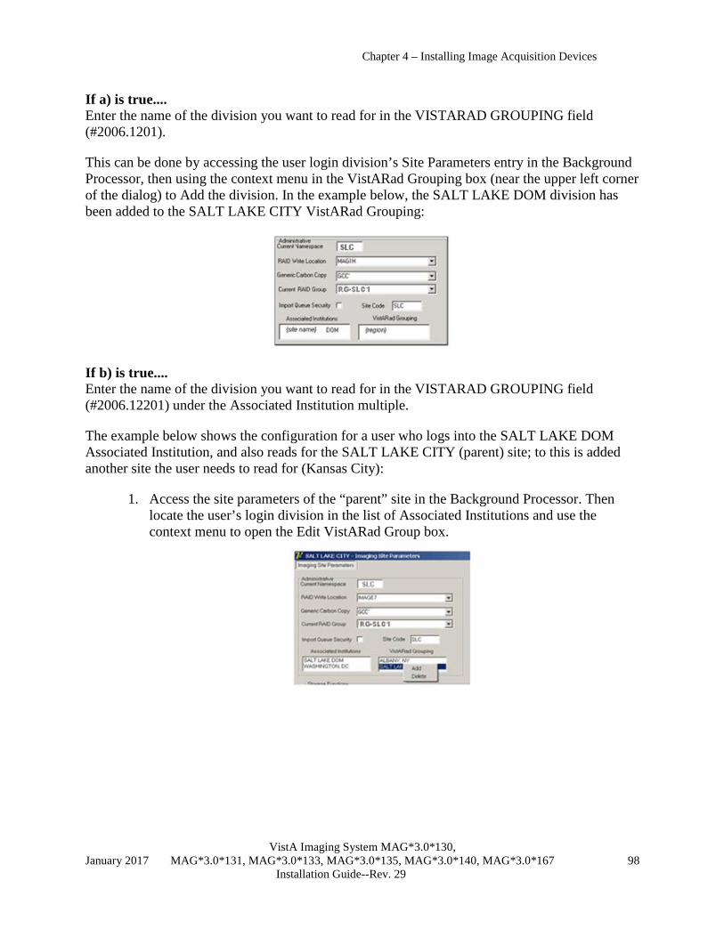
Chapter 4 – Installing Image Acquisition Devices
VistA Imaging System MAG*3.0*130, January 2017 MAG*3.0*131, MAG*3.0*133, MAG*3.0*135, MAG*3.0*140, MAG*3.0*167 98 Installation Guide--Rev. 29
If a) is true.... Enter the name of the division you want to read for in the VISTARAD GROUPING field (#2006.1201).
This can be done by accessing the user login division’s Site Parameters entry in the Background Processor, then using the context menu in the VistARad Grouping box (near the upper left corner of the dialog) to Add the division. In the example below, the SALT LAKE DOM division has been added to the SALT LAKE CITY VistARad Grouping:
If b) is true.... Enter the name of the division you want to read for in the VISTARAD GROUPING field (#2006.12201) under the Associated Institution multiple.
The example below shows the configuration for a user who logs into the SALT LAKE DOM Associated Institution, and also reads for the SALT LAKE CITY (parent) site; to this is added another site the user needs to read for (Kansas City):
1. Access the site parameters of the “parent” site in the Background Processor. Then locate the user’s login division in the list of Associated Institutions and use the context menu to open the Edit VistARad Group box.

Chapter 4 – Installing Image Acquisition Devices
VistA Imaging System MAG*3.0*130, January 2017 MAG*3.0*131, MAG*3.0*133, MAG*3.0*135, MAG*3.0*140, MAG*3.0*167 99 Installation Guide--Rev. 29
2. In the Edit VistARad Group box, use Add on the context menu to open a list of divisions that can be read for.
3. Select the division you want to read for, and then click OK.
3.3.3 Detailed Configuration The VistARad System Options Menu [MAGJ MAIN] is used to set site parameters that control VistARad’s basic behaviors and to enhance performance, to create custom exam lists, and to review and manage VistARad’s prefetch capabilities.
Select OPTION NAME: VistARad System Options SITP E/E VistaRad Site Parameters ELIS E/E VistaRad Exam Lists PLIS Print VistaRad List Definition EPRF E/E VistaRad PreFetch Logic IPRF Inquire Prefetch Logic PPRF Print VistaRad Prefetch Logic Table ECPT E/E VistaRad CPT Matching Set ICPT Inquire VistaRad CPT Matching Set PCPT Print VistaRad CPT Matching Logic Table EPRO E/E VistARad Default User Profiles Select VistARad System Options Option:
This section explains how to set up the options controlled by the VistARad System Options menu.

Chapter 4 – Installing Image Acquisition Devices
VistA Imaging System MAG*3.0*130, January 2017 MAG*3.0*131, MAG*3.0*133, MAG*3.0*135, MAG*3.0*140, MAG*3.0*167 100 Installation Guide--Rev. 29
Note: Two additional VistARad-related options used for correcting processing issues in older CT and CR images are present in the DICOM Menu Options menu [MAGD DICOM MENU]. These options are described in detail in the DICOM User Manual.
3.3.3.1 VistARad Site Parameters The VistARad Site Parameters file (#2006.69) contains fields used to control basic aspects of how VistARad works. Changes made to these fields affect all VistARad workstations.
The VistARad Site Parameters file is accessed using the E/E VistARad Site Parameters [MAGJ VISTARAD SITE PARAMETERS) option in the VistARad System Options [MAGJ MAIN] menu. Each field is described below, listed in the order used on the back end. Valid values are listed in italics.
VISTARAD SITE NAME (#2006.69, .01) 3 – 30 character site name Text value identifying the site. Used as the primary key (IEN) for the file used to store VistARad site parameters. Currently, only one name per site may be used. For consolidation sites, this means that all divisions using VistARad will use the same set of site parameters.
ENABLE STATUS UPDATE? (#2006.69, .05) yes/no Grants a radiologist (a user defined as “Staff” in the Radiology Package) the capacity to lock an exam and change the exam’s status from “Examined” to “Interpreted.”
RECENT EXAMS DAYS LIMIT (#2006.69, 1) 2-99999 days Limits the contents of the Recent exams list to exams up to the specified number of days old (the Recent exams list shows all exams having a status of “Interpreted” or “Transcribed”). If a limit is not set using this field, the system defaults to a value of 6.
UNREAD EXAMS DAYS LIMIT (#2006.69, 2) 2-99999 days Limits the contents of the Unread exams list to exams up to the specified number of days old. If a limit is not set using this field, the system defaults to a value of 30.
PREFETCH ACTIVE? (#2006.69, 3) yes/no Prefetch determines if prior exams are retrieved from Tier 2 when a patient is registered in the Radiology Package. When active, prefetch allows quick access to prior related exams, because the exams in question have already been copied to short-term storage. When prefetch is not active, there will be a delay when a radiologist has to display a prior that has been archived on Tier 2.
Note: Prefetch is dependent on the settings in the HL7 package, and uses logic defined using the E/E VistARad Prefetch Logic [MAGJ E/E PREFETCH LOGIC] menu option. For more information, see section 3.3.3.2.7.
LIST ONLY EXAMS HAVING IMAGES? (#2006.69, 5) yes/no Determines if the Unread, Recent, and All Active exam lists show all exams, or only those exams that have images available for display. This setting will also affect custom lists defined using the “Pending” exam status.
ENABLE SERIES DISPLAY? (#2006.69, 5.5) yes/no Obsolete- retained for backward compatibility with Patch 32.

Chapter 4 – Installing Image Acquisition Devices
VistA Imaging System MAG*3.0*130, January 2017 MAG*3.0*131, MAG*3.0*133, MAG*3.0*135, MAG*3.0*140, MAG*3.0*167 101 Installation Guide--Rev. 29
Controls how multi-series exams are presented in the Layout Viewer. When enabled, each series within an exam will be displayed in a separate exam group window. When not enabled, all series in an exam will be displayed in a single group window. Note that workstation users have a separate preference that can be used to turn series processing on or off within the viewing session.
BACKGROUND COMPILE EXAM LISTS? (#2006.69, 6) yes/no When this field is set to Yes, the TaskMan jobs that compile the Unread and Recent lists run normally and allow the Unread and Recent lists to be retrieved very quickly.
• For information about scheduling the job used to compile the Recent list, refer to section 3.3.2.4.
• The possibility of the information in pre-compiled lists being outdated is minimized by the use of the UNREAD BKGND COMPILE INTERVAL and the RECENT COMPILE INTERVAL fields.
When this field is set to No, the jobs cancel, but continue to check this field using their defined intervals. As long this field is No, the Unread and Recent lists are generated on-demand (each time the user displays them). When created on-demand, the lists will contain the most recent Radiology Package information, but may take longer to display when the lists are selected by the user.
UNREAD BKGND COMPILE INTERVAL (#2006.69, 7) 2 – 15 minutes Defines the number of minutes to wait between each successive compile of the Unread exams list. If not specified, this field defaults to 6. For sites that tend to have more than 100 unread exams, a value of 3 or 4 minutes is recommended; for sites with fewer than 100 unread exams, use 2 or 3 minutes. This field is active only when BACKGROUND COMPILE EXAM LISTS is set to Yes.
Note: Exams ready for interpretation (case-edited to “Examined”) after the Unread list has been compiled will not appear until the next time the Unread list is compiled. However, exams that are advanced to a status of “Interpreted” will be dropped from the Unread list, even between compiles.

Chapter 4 – Installing Image Acquisition Devices
VistA Imaging System MAG*3.0*130, January 2017 MAG*3.0*131, MAG*3.0*133, MAG*3.0*135, MAG*3.0*140, MAG*3.0*167 102 Installation Guide--Rev. 29
RECENT BKGND COMPILE INTERVAL (#2006.69, 7.2) 30 – 240 minutes This field should match the defined interval used in TaskMan for the MAGJ SCHED RECENT LIST COMPILE job. This field is used to notify a VistARad user if the MAGJ SCHED RECENT LIST COMPILE job has not run for more than the defined interval of time. This field is active only when BACKGROUND COMPILE EXAM LISTS is set to Yes.
Note: Exams that have advanced to a status of “Complete” after the Recent list has been compiled will not be removed until the next time the Recent list is compiled. However, exams that have advanced to a status of “Transcribed” will be added to the Recent list, even between compiles.
For more information about compiling the Recent exam list, refer to the information in section 3.3.2.4.
REMOTE LIST ONLY REMOTE CACHE? (#2006.69, 8) yes/no Obsolete- retained for backward compatibility with Patch 32. Determines how the Unread and Recent exam lists are presented to remote VistARad users. When set to Yes, the Unread and Recent exam lists presented to remote VistARad users will show only the exams that have been routed to their site. When set to No, all exams will be included in the exam lists.
SITE SENDS TO REMOTE CACHE (#2006.69, 9) yes/no Used only for sites that route exams. See the Routing User Guide for details. Setting this field to Yes turns on extra processing that is needed for VistARad to properly manage routed exams. One of the results of setting this field to Yes is the addition of the RC column to VistARad’s exam lists.
PATIENT LIST LIMIT # YEARS (#2006.69, 10) 2 – 20 years Obsolete- retained for backward compatibility with Patch 32. Use this field to control how far back in time the Patient Exams list should go. Greater efficiency in compiling this list is achieved by limiting the number of years to a “clinically useful” value of 5 to 7 years. When no value is defined for this field, the Patient Exams list will include the earliest exams on record for a patient (subject to the maximum number of exams defined in PATIENT LIST LIMIT # EXAMS).
PATIENT LIST LIMIT # EXAMS (#2006.69, 11) 15 - 75 Obsolete- retained for backward compatibility with Patch 32. Use this field to define the maximum number of exams that can appear in Patient Exams list. A recommended value would be about 30 to 40 exams. When no value is defined for this field, the Patient Exams list will include all exams on record for a patient (subject to the maximum age of exams defined in PATIENT LIST LIMIT # YEARS).
REQUISITION FOR RAD STAFF ONLY (#2006.69, 12) yes/no Setting this field to Yes restricts the display of exam requisitions to users defined as staff radiologists in the Radiology Package. Setting this field to No allows any VistARad user to display exam requisitions regardless of their user definition in the Radiology Package.

Chapter 4 – Installing Image Acquisition Devices
VistA Imaging System MAG*3.0*130, January 2017 MAG*3.0*131, MAG*3.0*133, MAG*3.0*135, MAG*3.0*140, MAG*3.0*167 103 Installation Guide--Rev. 29
ENA DICT PREF-YES ALL LOCKED (#2006.69, 13) yes/no Determines if the Default the Dictation dialog to ‘Yes’ for ALL locked exams user preference in the VistARad Dictation Settings dialog can be set as desired by individual users. When ENA DICT PREF-YES ALL LOCKED field is set to its default value of NO, this user preference is disabled site-wide. Functionality of the user preference is covered in the “VistARad and Voice Dictation” chapter of the VistARad User Guide.
UNREAD LIST PRIORITY SEQ (#2006.69, 20) see below Defines the priority-based sort order used in the Unread list. Based on four values indicating priority derived from the RAD/NUC MED ORDERS file (#75.1).
The default order is: Stat, Urgent, Pre-op, Routine. To achieve this ordering, the value for this field would be specified as S,U,P,R.
Any sequence of these four letters may be defined (do not use spaces; all four letters must be used). Regardless of the sequence defined, the oldest exam in a given status is displayed first.
TIMEOUT WINDOWS VISTARAD (#2006.1, 123) number of minutes Determines the amount of inactive time to wait before a user is automatically logged out of a VistARad workstation. Affects all workstations at a site (or division, if the site is multi-divisional). If a value is not set, workstations will automatically log out after 30 minutes of user inactivity.
Note: While this field is stored in the IMAGING SITE PARAMETERS File (#2006.1), it is accessed using the prompts to edit VistARad’s site parameters.
This setting can be overridden on a workstation-by-workstation basis by setting a value in MAGJ.INI (details in section 3.2.4.3).
3.3.3.2 Defining Custom Exam Lists Once basic configuration is complete, VistARad’s standard exam lists (Unread, Recent and All Active) can be used to list all exams within a specific status category. For most sites, it is beneficial to further subdivide the pool of unread exams by defining custom exam lists. Custom exam lists allow VistARad workstations to reflect how the department’s interpretation work is distributed between radiology staff.
Once a custom list is defined and enabled, VistARad workstation users will be able to access the custom list using an option under the Viewer menu and/or a button that appears with the VistARad Manager window.
Note: The Imaging Coordinator will need to work with radiology management to design custom lists suitable for each site.

Chapter 4 – Installing Image Acquisition Devices
VistA Imaging System MAG*3.0*130, January 2017 MAG*3.0*131, MAG*3.0*133, MAG*3.0*135, MAG*3.0*140, MAG*3.0*167 104 Installation Guide--Rev. 29
3.3.3.2.1 Menu Options for Custom Lists Custom exam list definitions can be accessed and changed from the VistARad System Options menu [MAGJ MAIN].
Select OPTION NAME: VRAD VistARad System Options SITP E/E VistaRad Site Parameters ELIS E/E VistaRad Exam Lists PLIS Print VistaRad List Definition EPRF E/E VistaRad PreFetch Logic IPRF Inquire Prefetch Logic PPRF Print VistaRad Prefetch Logic Table ECPT E/E VistaRad CPT Matching Set ICPT Inquire VistaRad CPT Matching Set PCPT Print VistaRad CPT Matching Logic Table EPRO E/E VistARad Default User Profiles Select VistARad System Options Option:
The Print VistARad List Definition [MAGJ LIST INQUIRY] option is used to display existing exam list definitions. The following definitions are pre-defined and cannot be changed.
Exam list Contains exams with status of Unread EXAMINED Recent INTERPRETED, TRANSCRIBED All Active EXAMINED, INTERPRETED, and
TRANSCRIBED
The E/E VistARad Exam Lists [MAGJ E/E VISTARAD LISTS] option is used to create and edit custom exam lists.
Note: Once created, custom lists cannot be deleted. However, all fields used to define custom lists can be re-defined, and the list itself can be disabled.
Note: Do not create or edit exam list definitions directly using VA FileMan. Changes made using VA FileMan will not work.
3.3.3.2.2 Creating Custom Lists Follow the steps below to create custom exam lists. For information about specific fields, use ?? at a prompt or refer to the descriptions in the following section.
1. From the VistARad System Options [MAGJ MAIN] menu, choose the E/E VistARad Exam Lists [MAGJ E/E VISTARAD LISTS] option.
2. At each prompt, enter values used to define the basic properties of the list you are creating. A sample screen is shown below, with user input in bold:
Select MAG RAD LISTS DEFINITION NAME: URGENT MR Are you adding 'URGENT MR' as a new MAG RAD LISTS DEFINITION (the 10TH)? No// Y (Yes) NAME: URGENT MR//

Chapter 4 – Installing Image Acquisition Devices
VistA Imaging System MAG*3.0*130, January 2017 MAG*3.0*131, MAG*3.0*133, MAG*3.0*135, MAG*3.0*140, MAG*3.0*167 105 Installation Guide--Rev. 29
LIST #: 10// (No Editing) BUTTON LABEL: URGENT MR LIST TYPE: U UNREAD ENABLE LIST?: Y Y Select COLUMN: CASE NUMBER WIDTH: Select COLUMN: EXAM LOCK INDICATOR WIDTH: Select COLUMN: PATIENT NAME WIDTH: … Select COLUMN: Select SORT: IMAGE DATE/TIME 1 IMAGE DATE/TIME 2 IMAGE DATE/TIME-SORTABLE CHOOSE 1-2: 2 IMAGE DATE/TIME-SORTABLE REVERSE?: N NO Select SORT: CASE NUMBER Select SORT:
3. After defining basic properties, you will be prompted to create a search logic definition. Note that for custom list creation, you are saving a search logic definition, rather than saving search logic results.
a. Define the search logic, using terms based on values displayed in VistARad’s exam lists. A sample screen is shown below, with user input in bold: … NOTES: EXAM LOCK INDICATOR will not work for search logic; REMOTE CACHE INDICATOR only works for Null/Not Null logic. -A- SEARCH FOR MAGJ ZLIST SEARCH FIELD: MODALITY -A- CONDITION: 5 EQUALS -A- EQUALS: MR -B- SEARCH FOR MAGJ ZLIST SEARCH FIELD: PRIORITY -B- CONDITION: 5 EQUALS -B- EQUALS: URGENT -C- SEARCH FOR MAGJ ZLIST SEARCH FIELD: IF: A B MODALITY EQUALS "MR" and PRIORITY EQUALS "URGENT" OR: …
b. After defining search logic, you will be prompted to store your definition. Always enter the values indicated in bold below. … STORE RESULTS OF SEARCH IN TEMPLATE: TEMP (Mar 08, 2002@12:50) User #131 File #2006.634 SEARCH DATA ALREADY STORED THERE....OK TO PURGE? NO// YES DESCRIPTION: 1> …
c. After storing your definition, cycle past the remaining prompts by pressing Enter (the remaining prompts are not used for custom lists). … SORT BY: CASE NUMBER//

Chapter 4 – Installing Image Acquisition Devices
VistA Imaging System MAG*3.0*130, January 2017 MAG*3.0*131, MAG*3.0*133, MAG*3.0*135, MAG*3.0*140, MAG*3.0*167 106 Installation Guide--Rev. 29
START WITH CASE NUMBER: FIRST// FIRST PRINT FIELD: Heading (S/C): MAGJ ZLIST SEARCH SEARCH Replace DEVICE: TELNET Right Margin: 80// >MAGJ ZLIST SEARCH SEARCH MAR 14,2002 10:34 PAGE 1 ---------------------------------------------------------------- *** NO RECORDS TO PRINT *** List Definition complete!
3.3.3.2.3 Fields Used to Define Custom Lists NAME – Specifies new or existing list name. Name will appear in the Manager window’s Preferences dialog. Name may be 3 to 75 characters in length.
BUTTON LABEL – Specifies the name that appears on the button used to open the custom list. Button Label may be 3 to 75 characters in length.
LIST TYPE – Determines what subset of exams to include in the custom list, based on the exam status. Choices are:
U Unread exams only; Exam Status Category= E(xamined) R Recent exams; Status Categories D(ictated) & T(ranscribed) A All active exams; Categories E, D, & T P Pending exams; Category= W(aiting for Exam) N N/A -- internal use only, not available for custom list definition.
ENABLE LIST? – Set to Yes to make list available to end user, set to No to make list unavailable. This option can be used to retire outdated lists as well. Note that user has a separate option to show or hide enabled custom lists from the VistARad Manager.
Select COLUMN – Use this field to select each column you want to have included in the custom list (columns order is defined internally). For each column you select, you will be asked to specify a column width (if you do not specify a width, a default value will be used).
• Entering a ?? at this field will display a list of all available columns.
• A recommended set of columns to use initially is listed below. For information about the type of information these columns contain, refer to the VistARad User Guide.
CASE NUMBER EXAM LOCK IND PATIENT NAME PATIENT ID PRIORITY PROCEDURE MODIFIER CPT CODE IMAGE DATE/TIME

Chapter 4 – Installing Image Acquisition Devices
VistA Imaging System MAG*3.0*130, January 2017 MAG*3.0*131, MAG*3.0*133, MAG*3.0*135, MAG*3.0*140, MAG*3.0*167 107 Installation Guide--Rev. 29
STATUS NUMBER OF IMAGES ONLINE STATUS MODALITY IMAGING LOCATION INTERPRETING RADIOLOGISTS
Select SORT – Use this field to specify each column you want the list sorted by. Columns are sorted in ascending order. If you select a numeric or date-based column, you will have the option of reversing the sort order.
MODIFY SEARCH LOGIC – If you are modifying an existing list, this prompt will be displayed. If you need to modify the search logic, enter YES (you will have to re-enter the search logic in its entirety). Entering YES will cause the existing logic to be deleted, and the prompts described below will be entered. Entering No will end the custom list definition process.
3.3.3.2.4 Defining Custom List Search Logic Defining search logic is very similar to standard VA FileMan searches, in the following respects:
• You enter the search conditions (truth tests) to perform. • You specify how the search conditions should be combined (link them together with
logical ANDs & ORs) to select records. Note: For detailed information, refer to Part I, Chapter 3 in the VA FileMan Getting Started manual.
When you are defining search logic for custom lists:
• Your search criteria must be defined in terms of the displayed values in VistARad’s exam lists (none of the values point to any actual file).
• When you are prompted to store your search, you must always enter the following values: STORE RESULTS OF SEARCH IN TEMPLATE – Always enter TEMP. If another value is entered, search logic will not be saved.
OK TO PURGE? – Always enter Yes.
• When you are prompted to format your output, do not enter values for the prompts shown below (these fields are not applicable to the creation of custom lists).
DESCRIPTION SORT BY START WITH FIRST PRINT FIELD: Heading (S/C): MAGJ ZLIST SEARCH SEARCH Replace

Chapter 4 – Installing Image Acquisition Devices
VistA Imaging System MAG*3.0*130, January 2017 MAG*3.0*131, MAG*3.0*133, MAG*3.0*135, MAG*3.0*140, MAG*3.0*167 108 Installation Guide--Rev. 29
3.3.3.2.5 How Prefetch Works Prefetch is what automatically retrieves archived images for prior related radiology exams from Tier 2 to the Tier 1 to speed subsequent display at a VistARad workstation. When prefetch is not active, a radiologist wishing to review an exam that has been archived will have to wait until the images are retrieved from Tier 2. When prefetch is active, exams that qualify as prior related exams take no longer to retrieve than current exams. Prefetch is triggered by the “Register Patient for Exams” function of the Radiology Package (via HL7 message processing).
Rules for determining which exams to retrieve are defined in the MAG RAD PRIOR EXAMS LOGIC file (#2006.65). This table maps the CPT (Current Procedural Terminology) code for the current exam to CPT codes of prior related exams of interest. For each prior CPT code mapped, the number and age or exams to prefetch can be specified.
A sample prefetch rule in the MAG RAD PRIOR EXAMS LOGIC file might be this:
CURRENT CASE CPT GROUP: 71020—CHEST 2 VIEWS MATCHING CPT GROUP: 71020—CHEST 2 VIEWS VERSION LIMIT-PREFETCH: 2 MATCHING CPT GROUP: 71010—CHEST SINGLE VIEW VERSION LIMIT-PREFETCH: 2 MATCHING CPT GROUP: 71250—CT THORAX W/O CONT VERSION LIMIT-PREFETCH: 1 DAYS LIMIT-PREFETCH: 3650 MATCHING CPT GROUP: 71250—CT THORAX W CONT VERSION LIMIT-PREFETCH: 1 DAYS LIMIT-PREFETCH: 3650
The equivalent logic would be this:
If an exam with CPT Code 71020 is registered, search the archive and retrieve: Up to 2 prior exams with CPT Code 71020; and Up to 2 prior exams with CPT Code 71010; and 1 exam with CPT Code 71250 if exam is less than 10 years old; and 1 exam with CPT Code 71260 if exam is less than 10 years old.
3.3.3.2.6 Enabling Prefetch Use the following procedures to verify that Prefetch settings are all in place.
1. Log in to the VistA system and check the following settings:
a. In the Protocol file (#101), use VA FileMan to verify that MAGJ PREFETCH/SEND ORM is defined as a Subscriber to the RA REG protocol. A sample Inquiry screen follows, showing the relevant fields in bold:

Chapter 4 – Installing Image Acquisition Devices
VistA Imaging System MAG*3.0*130, January 2017 MAG*3.0*131, MAG*3.0*133, MAG*3.0*135, MAG*3.0*140, MAG*3.0*167 109 Installation Guide--Rev. 29
Select OPTION: INQUIRE TO FILE ENTRIES OUTPUT FROM WHAT FILE: OPTION// 101 PROTOCOL (2241 entries) Select PROTOCOL NAME: RA REG 1 RA REG Rad/Nuc Med exam registered 2 RA REG 2.3 Rad/Nuc Med exam registered for HL7 v2.3 message CHOOSE 1-2: 1 RA REG Rad/Nuc Med exam registered ANOTHER ONE: STANDARD CAPTIONED OUTPUT? Yes// (Yes) Include COMPUTED fields: (N/Y/R/B): NO// - No record number (IEN), no Computed Fields NAME: RA REG ITEM TEXT: Rad/Nuc Med exam registered TYPE: event driver CREATOR: IMAGUSER, ONE PACKAGE: RADIOLOGY/NUCLEAR MEDICINE DESCRIPTION: This protocol is triggered whenever a radiology/ Nuclear Medicine exam is registered. It executes code that creates an HL7 ORM message consisting of PID, ORC, OBR and OBX segments. The message contains all relevant information about the exam, including procedure, time of registration, procedure modifiers, patient allergies, and clinical history. ITEM: MAGD SEND ORM ENTRY ACTION: Q TIMESTAMP: 58481,48067 SENDING APPLICATION: RA-SERVER-IMG TRANSACTION MESSAGE TYPE: ORM EVENT TYPE: O01 VERSION ID: 2.1 RESPONSE PROCESSING ROUTINE: Q SUBSCRIBERS: MAGD SEND ORM SUBSCRIBERS: MAGJ PREFETCH/SEND ORM
b. In the HL7 APPLICATION PARAMETER file (#771), verify that MAGJ CLIENT is set to “Active.” A sample Inquiry screen follows, showing the relevant fields in bold: OUTPUT FROM WHAT FILE: PROTOCOL// HL7 APPLICATION PARAMETER (39 entries) Select HL7 APPLICATION PARAMETER NAME: MAGJ-CLIENT ACTIVE ANOTHER ONE: STANDARD CAPTIONED OUTPUT? Yes// (Yes) Include COMPUTED fields: (N/Y/R/B): NO// - No record number (IEN), no Computed Fields NAME: MAGJ-CLIENT ACTIVE/INACTIVE: ACTIVE
c. In the MAG VistARad Site Parameters file (#2006.69), set PREFETCH ACTIVE? to “YES.”
2. On the Background Processor, do the following:
a. Choose Edit | BP Servers.
b. Make sure the Prefetch is assigned to a Background Processor.
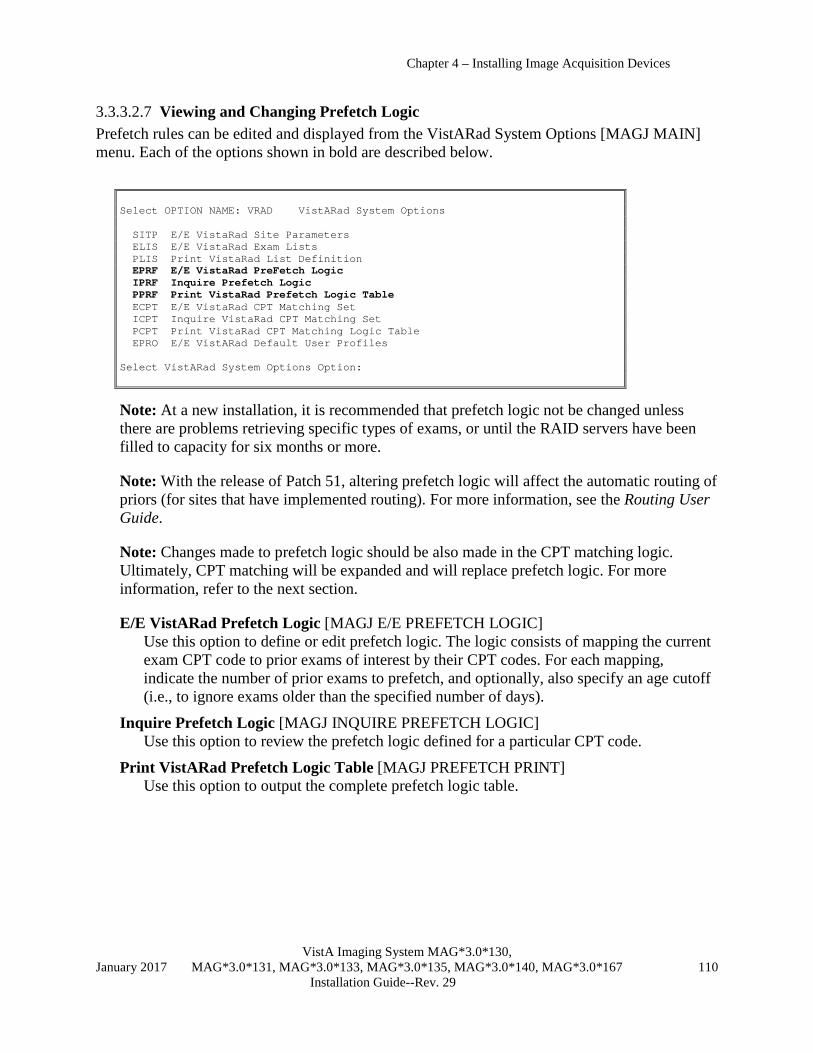
Chapter 4 – Installing Image Acquisition Devices
VistA Imaging System MAG*3.0*130, January 2017 MAG*3.0*131, MAG*3.0*133, MAG*3.0*135, MAG*3.0*140, MAG*3.0*167 110 Installation Guide--Rev. 29
3.3.3.2.7 Viewing and Changing Prefetch Logic Prefetch rules can be edited and displayed from the VistARad System Options [MAGJ MAIN] menu. Each of the options shown in bold are described below.
Select OPTION NAME: VRAD VistARad System Options SITP E/E VistaRad Site Parameters ELIS E/E VistaRad Exam Lists PLIS Print VistaRad List Definition EPRF E/E VistaRad PreFetch Logic IPRF Inquire Prefetch Logic PPRF Print VistaRad Prefetch Logic Table ECPT E/E VistaRad CPT Matching Set ICPT Inquire VistaRad CPT Matching Set PCPT Print VistaRad CPT Matching Logic Table EPRO E/E VistARad Default User Profiles Select VistARad System Options Option:
Note: At a new installation, it is recommended that prefetch logic not be changed unless there are problems retrieving specific types of exams, or until the RAID servers have been filled to capacity for six months or more.
Note: With the release of Patch 51, altering prefetch logic will affect the automatic routing of priors (for sites that have implemented routing). For more information, see the Routing User Guide.
Note: Changes made to prefetch logic should be also made in the CPT matching logic. Ultimately, CPT matching will be expanded and will replace prefetch logic. For more information, refer to the next section.
E/E VistARad Prefetch Logic [MAGJ E/E PREFETCH LOGIC] Use this option to define or edit prefetch logic. The logic consists of mapping the current exam CPT code to prior exams of interest by their CPT codes. For each mapping, indicate the number of prior exams to prefetch, and optionally, also specify an age cutoff (i.e., to ignore exams older than the specified number of days).
Inquire Prefetch Logic [MAGJ INQUIRE PREFETCH LOGIC] Use this option to review the prefetch logic defined for a particular CPT code.
Print VistARad Prefetch Logic Table [MAGJ PREFETCH PRINT] Use this option to output the complete prefetch logic table.

Chapter 4 – Installing Image Acquisition Devices
VistA Imaging System MAG*3.0*130, January 2017 MAG*3.0*131, MAG*3.0*133, MAG*3.0*135, MAG*3.0*140, MAG*3.0*167 111 Installation Guide--Rev. 29
3.3.3.3 CPT Matching CPT matching is used to automatically select an appropriate hanging protocol for an exam being opened. CPT matching is also used within a hanging protocol to identify which prior exams should be displayed automatically. CPT matching logic is pre-defined and does not need to be explicitly enabled.
Presently, CPT matching logic functions independently from prefetch. In future versions of VistARad, CPT matching logic will be expanded to incorporate the existing prefetch functionality.
3.3.3.3.1 CPT Matching Menu Options CPT matching logic is used by hanging protocols when automatically determining which priors to retrieve. CPT matching logic can be viewed1, printed, or changed using the following options in the VistARad System Options [MAGJ MAIN] menu:
Select OPTION NAME: VRAD VistARad System Options SITP E/E VistaRad Site Parameters ELIS E/E VistaRad Exam Lists PLIS Print VistaRad List Definition EPRF E/E VistaRad PreFetch Logic IPRF Inquire Prefetch Logic PPRF Print VistaRad Prefetch Logic Table ECPT E/E VistaRad CPT Matching Set ICPT Inquire VistaRad CPT Matching Set PCPT Print VistaRad CPT Matching Logic Table EPRO E/E VistARad Default User Profiles Select VistARad System Options Option:
E/E VistaRad CPT Matching Set [MAGJ E/E CPT MATCHING SET] Use this option to define or edit CPT matching logic. For details, see the following section.
Inquire VistaRad CPT Matching Set [MAGJ INQUIRE CPT MATCHING SET] Use this option to review the matching logic defined for a particular CPT code.
Print VistaRad CPT Matching Logic Table [MAGJ PRINT CPT MATCHING LOGIC] Use this option to output the complete CPT matching logic table.
1 CPT matching logic can be viewed from the VistARad Client using the Imaging Data window (see “Using the Imaging Data Window” in the VistARad User Guide).
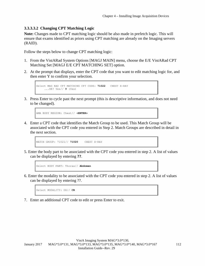
Chapter 4 – Installing Image Acquisition Devices
VistA Imaging System MAG*3.0*130, January 2017 MAG*3.0*131, MAG*3.0*133, MAG*3.0*135, MAG*3.0*140, MAG*3.0*167 112 Installation Guide--Rev. 29
3.3.3.3.2 Changing CPT Matching Logic Note: Changes made to CPT matching logic should be also made in prefetch logic. This will ensure that exams identified as priors using CPT matching are already on the Imaging servers (RAID).
Follow the steps below to change CPT matching logic:
1. From the VistARad System Options [MAGJ MAIN] menu, choose the E/E VistARad CPT Matching Set [MAGJ E/E CPT MATCHING SET] option.
2. At the prompt that displays, enter the CPT code that you want to edit matching logic for, and then enter Y to confirm your selection.
Select MAG RAD CPT MATCHING CPT CODE: 71022 CHEST X-RAY ...OK? Yes// Y (Yes)
3. Press Enter to cycle past the next prompt (this is descriptive information, and does not need to be changed).
AMA BODY REGION: Chest// <ENTER>
4. Enter a CPT code that identifies the Match Group to be used. This Match Group will be associated with the CPT code you entered in Step 2. Match Groups are described in detail in the next section.
MATCH GROUP: 71021// 71020 CHEST X-RAY
5. Enter the body part to be associated with the CPT code you entered in step 2. A list of values can be displayed by entering ??.
Select BODY PART: Thorax// Abdomen
6. Enter the modality to be associated with the CPT code you entered in step 2. A list of values can be displayed by entering ??.
Select MODALITY: DX// CR
7. Enter an additional CPT code to edit or press Enter to exit.

Chapter 4 – Installing Image Acquisition Devices
VistA Imaging System MAG*3.0*130, January 2017 MAG*3.0*131, MAG*3.0*133, MAG*3.0*135, MAG*3.0*140, MAG*3.0*167 113 Installation Guide--Rev. 29
3.3.3.3.3 How Match Groups Work For a given CPT code, Match Groups are used to define which other CPT codes qualify as “similar.” Similar CPTs come into play under these conditions:
• There is not an exact match between the CPT code (procedure) of a current exam being opened and the CPT code defined in any of the available hanging protocols.
• A hanging protocol has been defined to use “Similar CPT” matching for selection and automatic display of priors.
The table below lists CPT matching information for several types of chest x-rays. In this table, the CPT code 71020 is used as a Match Group. CPT MATCH CODE GROUP BODY PART MODALITY ----------------------------------- 71010 71020 Thorax CR DX 71015 Thorax CR DX 71020 Thorax CR DX 71021 Thorax CR DX 71022 71020 Thorax CR DX 71023 71020 Thorax RF CR DX 71030 Thorax CR DX 71034 Thorax RF CR DX 71035 Thorax CR DX
The resulting logic is that for any CPT with a Match Group of 71020, the CPTs listed below are considered “similar,” and will be considered for hanging protocol matching or prior selection purposes. (Because CPT 71020 serves as the basis of the Match Group, it is also treated as a member of the Match Group.)
71010 71020 71022 71023
Note that other CPTs in the table above (such as 71015) do not have a Match Group defined. For such CPTs, priors can only be searched for based on exact CPT matches and body part/modality matches; similar CPT matching is not currently defined.
3.3.3.4 Setting VistARad Default User Profiles The E/E VistARad Default User Profiles [MAGJ E/E DEFAULT USER PROFILES] option allows the system administrator to define default user profile entries for radiologist and non-radiologist user types.
Select OPTION NAME: VRAD VistARad System Options SITP E/E VistaRad Site Parameters ELIS E/E VistaRad Exam Lists PLIS Print VistaRad List Definition EPRF E/E VistaRad PreFetch Logic IPRF Inquire Prefetch Logic

Chapter 4 – Installing Image Acquisition Devices
VistA Imaging System MAG*3.0*130, January 2017 MAG*3.0*131, MAG*3.0*133, MAG*3.0*135, MAG*3.0*140, MAG*3.0*167 114 Installation Guide--Rev. 29
PPRF Print VistaRad Prefetch Logic Table ECPT E/E VistaRad CPT Matching Set ICPT Inquire VistaRad CPT Matching Set PCPT Print VistaRad CPT Matching Logic Table EPRO E/E VistARad Default User Profiles Select VistARad System Options Option:
Once a user of each type is configured, this option makes their configuration available to new – or existing – users. This can simplify the process of configuring new users. See the VistARad User Guide, “New VistARad User Setup,” for details.
Note: There is no filter on the assignment. The default non-radiologist profile may belong to a radiologist, and vice-versa. This gives the system administrator maximum flexibility when using the option.
Note: The option uses two fields in the IMAGING SITE PARAMETERS file (#2006.1) : DEFAULT VISTARAD USERPREF RAD (#202) and DEFAULT VISTARAD USERPREF NON (#203). They point to the MAGJ USER DATA file (#2006.68).
3.4 Testing a VistARad Installation This section explains how to confirm that VistARad functions properly within VistA Imaging. It assumes that the person performing the testing is familiar with the basic operation of VistARad.
Note: The steps in these sections can be used to verify proper integration of VistARad in your radiology department’s workflow. It is expected that each site will also use its own requirements to verify that image display is of proper quality for diagnostic purposes.
3.4.1 Requirements for Testing Before VistARad can be tested, the following steps must be completed:
• Status Codes for Imaging Types associated with soft-copy reading must be set up and associated with VistARad status codes (using the Radiology Package).
• The VistARad site parameter ENABLE STATUS UPDATE must be set to Yes. • VistARad client software must be installed on at least one diagnostic workstation. • At least one test patient with an associated radiology exam, with a status of “Examined,”
must be created. • The test exam must have images. Ideally, the test exam should be a CR exam and have a
total size of 7 to 10 MB. • The person performing the testing will need to use an access/verify code that has been
designated as “Staff” in the Radiology Package. Note: If your site has chosen to use prefetch or custom lists, your site will need to establish standards and test for proper function of these features as well.

Chapter 4 – Installing Image Acquisition Devices
VistA Imaging System MAG*3.0*130, January 2017 MAG*3.0*131, MAG*3.0*133, MAG*3.0*135, MAG*3.0*140, MAG*3.0*167 115 Installation Guide--Rev. 29
3.4.2 Performing Testing Use the steps below to test VistARad. Note that many of these steps will rely on exam list updates which, depending on how VistARad is set up at your site, may take a few minutes to initially complete. These steps assume that a test exam is available.
1. At a VistARad workstation, log in and open the Unread list. Confirm that a test exam is present in the Unread list, and that the value in the Status field is “Examined.”
2. Open the test exam. A 7-to-10 MB test exam should open in two seconds or less.
3. If you have enabled voice dictation integration, verify that the correct report is opened in the voice dictation software.
4. Once the exam is displayed, reopen the Unread list and confirm that your login initials appear in the Lock column.
5. Adjust the test exam’s display properties (scale, window/level, layout, etc.), and ensure that the images respond properly.
6. Click to open Update Status/Close Exams window, and update the status of the test exam to “Interpreted” (in the window, set “Interp” to Yes).
7. Confirm that the test exam is removed from the Unread exam list. In an exam list that contains interpreted exams (Recent, All Active, etc.), verify that your login initials are reflected in the “Interp By” field, and that the status of the exam is “Interpreted.”
Note: At sites that use the Background Compile feature, the addition of “Interpreted” exams to the Recent list is dependent on the re-compile of the Unread exam list. It might take a few minutes for the exam to appear.
8. Use your site’s reporting software to enter a report for the test exam. After entering the report, use the Recent or All Active list to confirm that the exam status has been updated to “Transcribed.”
9. Use your site’s reporting software to verify the report for the test exam. After verifying the report, use the Recent or All Active list to confirm that the exam status has been updated to “Complete,” and that the report can be accessed.
3.5 Running VistARad in Training Mode You can use VistARad in “training mode” when you want to make the software available for Staff Radiologist training purposes or before VistA configuration is complete. To use VistARad in training mode, do one of the following:
• To affect all VistARad workstations at a site, set the VistARad site parameter ENABLE STATUS UPDATE? field (#2006.69, .05) to No.
• To affect a single workstation, start the VistARad software and choose View | Settings | Manager | General. Then disable the Disable Exam Lock/Update checkbox.

Chapter 4 – Installing Image Acquisition Devices
VistA Imaging System MAG*3.0*130, January 2017 MAG*3.0*131, MAG*3.0*133, MAG*3.0*135, MAG*3.0*140, MAG*3.0*167 116 Installation Guide--Rev. 29
This setting affects all VistARad workstations. When status updates are disabled, no file updates of any kind are made by VistARad, making it safe to use on live exams during radiologist training/practice sessions.

VistA Imaging System MAG*3.0*130, January 2017 MAG*3.0*131, MAG*3.0*133, MAG*3.0*135, MAG*3.0*140, MAG*3.0*167 117
Installation Guide--Rev. 29
This page intentionally blank.


VistA Imaging System MAG*3.0*130, January 2017 MAG*3.0*131, MAG*3.0*133, MAG*3.0*135, MAG*3.0*140, MAG*3.0*167 119
Installation Guide--Rev. 29
Chapter 4 Installing Image Acquisition Devices The VistA Imaging Clinical Capture program can be set up to captures images from:
• Medical instruments that produce RGB, S-video, or composite video output (via image capture boards)
• Digital cameras (must have a TWAIN interface or be able to download standard format images such as JPEG to a workstation)
• Color and grayscale scanners with TWAIN interface
• X-ray scanners (film digitizers)
• Import of images from workstation’s local hard drive Setup guidelines for the use of these devices with Clinical Capture is proved in this chapter.
Note: Clinical Capture workstations can also import standard format images (e.g., AVI, JPEG, TIF, TGA, BMP, etc.) from a local or mapped hard drive.
4.1 Video Inputs The process of acquiring digital images from an analog video signal is called “frame grabbing”. In frame grabbing, a live video image is displayed on the workstation’s monitor and still images can be captured and saved. This process normally takes place in 1/30 second.
A typical frame-grabbed image consists of 480 lines with 640 pixels per line. Pixels typically contain 24 bits for color (8 bits for red, 8 bits for green, and 8 bits for blue, for 16 million total colors) or 8 bits for grayscale (256 shades of gray). Other pixel depths are possible.
For the Clinical Capture workstation, frame grabbing requires a Matrox board, the appropriate type of cable, and medical equipment that produces a video signal.
Note: AVI images can be acquired using Clinical Capture’s import capability. AVI images are not considered ‘video inputs’ for the purposes of this section.
Chapter 4 – Installing Image Acquisition Devices
VistA Imaging System MAG*3.0*130, January 2017 MAG*3.0*131, MAG*3.0*133, MAG*3.0*135, MAG*3.0*140, MAG*3.0*167 120 Installation Guide--Rev. 29
4.1.1 Video Capture Board Installation and Setup
4.1.1.1 Capture Board and Cable Information In addition to the Capture workstation and the instrument that will be used to produce the images, the following is needed:
• An image capture board. Supported boards are listed below. Be sure that the image capture board can handle the type of output signal that is available.
o Matrox Orion board: Handles RGB, S-video, and composite video inputs. A VGA output is built into the board, eliminating the display compatibility issues that exist with the Meteor II boards. The Orion board can be purchased for AGP or PCI slots.
o The Matrox Meteor II/Standard board: Handles S-video and composite inputs. Does not support RGB. PCI only.
o The Matrox Meteor II/Multi-Channel: Handles RGB video inputs. Does not support S-video or composite video. PCI only.
Note: Both Meteor II boards require an additional Matrox or Matrox G series display card for the display of live video feed in real time (30 frames per second).
• A cable to connect the capture board to the medical instrument. o Cables can be purchased separately from the board vendor or can be built by
comparing the output pin configuration of the instrument to the input pin configuration of the Matrox board. The pin configuration of each is listed in the manuals that accompany the device.
o For RGB sources, you will need to compare the mapping of the signals to the pin numbers of the source connector and the capture board input connector. If they do not match, you will need to have a correct cable made; be sure to label the ends of the cable for the input source and image-capture board.
The capture board will need to be installed according to vendor instructions. Instructions for driver installation and Capture software configuration are included in the next two sections.
4.1.1.2 Matrox MIL 7.5 Driver Installation The following steps are to be performed only for Capture workstations using Matrox capture boards. The MIL (Matrix Imaging Library) software is included in VistA Imaging distributions.
1. Log into the workstation as an administrator.
2. Locate and run the Mil7.5.exe file. When prompted, select a temporary folder where the unzipped files should be stored (i.e., MatroxInstall).
3. Run Setup.exe from the temporary folder.
4. When the Master Setup dialog displays, choose ActiveMil, and click Continue.
Note: If an older version of the MIL is detected, you will be prompted to remove it.

Chapter 4 – Installing Image Acquisition Devices
VistA Imaging System MAG*3.0*130, January 2017 MAG*3.0*131, MAG*3.0*133, MAG*3.0*135, MAG*3.0*140, MAG*3.0*167 121 Installation Guide--Rev. 29
5. Accept the default destination folder on the Matrox Imaging Products window, and then
click Next.
6. In the Matrox Imaging Driver dialog, select the drivers that match the installed board, and select VGA. Then click Next.
7. Accept the defaults for the remaining prompts. After clicking OK in the last dialog, the
software will be installed.
8. When you are prompted to restart the computer, click Yes, then click Finish.
9. After installation of the drivers is complete, Capture workstation configuration will need to be performed and/or verified. See the next section for details.
4.1.1.3 Capture Workstation Configuration for Matrox Perform the following steps after installing or updating Matrox drivers on a Capture workstation. (For workstations where drivers are being updated, use these to verify that no Capture software settings were inadvertently changed.)
1. Log into the VistA system and start the VistA Imaging Capture application.

Chapter 4 – Installing Image Acquisition Devices
VistA Imaging System MAG*3.0*130, January 2017 MAG*3.0*131, MAG*3.0*133, MAG*3.0*135, MAG*3.0*140, MAG*3.0*167 122 Installation Guide--Rev. 29
2. At the top of the Capture window, click the Source label.
3. In the Select Input Source box, select the Meteor option. Then click the Settings button that
appears.
4. The ActiveMIL Property Defaults window will appear. . Set the options for each tab as described below. Click OK to close the dialog when you are finished.
• Under the System tab, click Detect to auto-select the board type:
• Under the Image tab, select the number of bands and size to use for captured images.
Typically, 3 bands (for full color) 640 x 480 can be selected. If more information is needed, refer to the documentation for the capturing instrument and for the Matrox board.
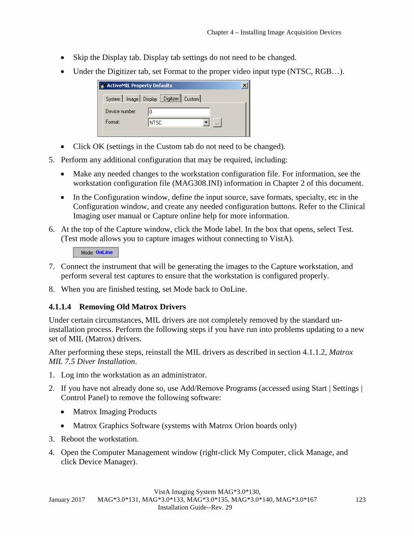
Chapter 4 – Installing Image Acquisition Devices
VistA Imaging System MAG*3.0*130, January 2017 MAG*3.0*131, MAG*3.0*133, MAG*3.0*135, MAG*3.0*140, MAG*3.0*167 123 Installation Guide--Rev. 29
• Skip the Display tab. Display tab settings do not need to be changed.
• Under the Digitizer tab, set Format to the proper video input type (NTSC, RGB…).
• Click OK (settings in the Custom tab do not need to be changed).
5. Perform any additional configuration that may be required, including:
• Make any needed changes to the workstation configuration file. For information, see the workstation configuration file (MAG308.INI) information in Chapter 2 of this document.
• In the Configuration window, define the input source, save formats, specialty, etc in the Configuration window, and create any needed configuration buttons. Refer to the Clinical Imaging user manual or Capture online help for more information.
6. At the top of the Capture window, click the Mode label. In the box that opens, select Test. (Test mode allows you to capture images without connecting to VistA).
7. Connect the instrument that will be generating the images to the Capture workstation, and
perform several test captures to ensure that the workstation is configured properly.
8. When you are finished testing, set Mode back to OnLine.
4.1.1.4 Removing Old Matrox Drivers Under certain circumstances, MIL drivers are not completely removed by the standard un-installation process. Perform the following steps if you have run into problems updating to a new set of MIL (Matrox) drivers.
After performing these steps, reinstall the MIL drivers as described in section 4.1.1.2, Matrox MIL 7.5 Diver Installation.
1. Log into the workstation as an administrator.
2. If you have not already done so, use Add/Remove Programs (accessed using Start | Settings | Control Panel) to remove the following software:
• Matrox Imaging Products
• Matrox Graphics Software (systems with Matrox Orion boards only) 3. Reboot the workstation.
4. Open the Computer Management window (right-click My Computer, click Manage, and click Device Manager).

Chapter 4 – Installing Image Acquisition Devices
VistA Imaging System MAG*3.0*130, January 2017 MAG*3.0*131, MAG*3.0*133, MAG*3.0*135, MAG*3.0*140, MAG*3.0*167 124 Installation Guide--Rev. 29
5. In the View menu, make sure Show Hidden Devices is enabled. Then, on the left side of the window, select the Device Manager (under the System Tools entry).
• Check the right side of the window for the Matrox Imaging Adaptor. If it is present, remove it by right-clicking the entry and selecting Uninstall.
• Expand the Non-Plug and Play Drivers entry. Remove any entries named Matrox DMA Manager (there may be more than one), and any entries that reference the Matrox Orion board.
6. Navigate to the winnt\inf folder (Windows\inf for XP systems). If the following files are present, delete them.
• <yourboardname>.inf
• <yourboardname>.pnf 7. In the same folder, locate and open oemX.inf (where X is 0,1, etc.). If the first lines of this
file say “Matrox frame grabber support”, delete this file and the corresponding .pnf file.
8. Reboot the computer. IMPORTANT: As the computer restarts, press Cancel if Windows attempts to automatically install any drivers. If you are unable to interrupt the installation:
• Locate and delete the \PNPDRVRS\Video\Install.inf file.
• In the Device Manager, locate and remove any entries related to Matrox boards (for Orion boards, there may also be an entry under the Display tree).
• Reboot the computer and cancel out of any automatic driver installations. 9. In Registry Editor (Click Start | Run, then enter ‘regedit’ in the Run box), locate the
following. If they are present, delete them (right click the value, then click delete).
• In the HKEY_LOCAL_MACHINE / SYSTEM / CurrentControlSet /Services key, locate and delete the MtxDma0 key and any key named after the installed Matrox board.
• In the HKEY_LOCAL_MACHINE / SOFTWARE key, locate and delete the Matrox and Rainbow Technologies keys.
• In the HKEY_CURRENT_USER/ SOFTWARE key, locate and delete the Matrox key. 10. Reboot the computer. IMPORTANT: As the computer restarts, press Cancel if Windows
attempts to automatically install any drivers. If you are unable to interrupt the installation, perform the steps in step 7.
4.1.2 Setup Notes for Specific Instruments There are many types of medical equipment that produce video output appropriate for image capture. The following sections provide setup guidelines for specific instruments.
Note: Some instruments support a DICOM interface to VistA Imaging. If a DICOM interface is available, it should be used. DICOM interfaces allow image capture without direct user intervention. Check the VistA Imaging web page for status information.
Chapter 4 – Installing Image Acquisition Devices
VistA Imaging System MAG*3.0*130, January 2017 MAG*3.0*131, MAG*3.0*133, MAG*3.0*135, MAG*3.0*140, MAG*3.0*167 125 Installation Guide--Rev. 29
4.1.2.1 Endoscopy Equipment Your GI laboratory must be using a video endoscopy unit to capture and digitize GI images. Fuji, Olympus, and other units have been interfaced thus far to the VistA Imaging System (refer to the Imaging website for more information)
There are two ways to acquire the image signal from video endoscopy equipment:
• The endoscopy unit may have a processor box which provides output directly from RGB connectors, generally located on the back of the unit. This output can be fed to the frame grab board input connector on the Clinical Capture workstation using the appropriate cable.
• The endoscopy system will also display live video images on a monitor. The RGB signals can be obtained from the back of the endoscopy video monitor and passed directly to the frame grab board input connector.
It is also possible to capture the endoscopy procedure to videotape first, and then review the case to select still images for capture and distribution. This is not normally preferred because image fidelity is lost in the videotaping process (VHS video cassette recorders (VCRs) store analog images at half of the NTSC resolution), and because videotaping followed by capture requires more time.
4.1.2.2 Color Video Cameras Video cameras use CCD chips to produce an image from the input light. The CCD chip may vary in spatial resolution. Less expensive cameras use 1 CCD chip to produce the image. More expensive cameras use 3 CCD chips to improve the quality of color images.
The camera lens also affects image quality. Be sure that the video camera is equipped with a standard mount for the lens. The most common video camera lens mount is the C-mount; there are a variety of lenses available at reasonable cost for this mount. Other cameras may use the Fujinon or Nikon mount. In general, cameras are sold without the lens, allowing the purchaser to match the lens to the purpose of the camera. A lens that allows auto focus and auto iris is convenient. Good macro capability is necessary for close up work. The camera body (without the lens) may be placed on a microscope or other optical instrument equipped with a C-Mount adapter. Be sure these are parfocal so the user does not have to refocus when switching between microscope ocular and computer monitor display; this may require purchase of an additional adapter. Cameras should also be capable of being mounted on tripods.
Many color video cameras produce both RGB and composite signals. The RGB input is often supplied by a DB9 female connector.
4.1.2.3 Grayscale Image Capture For devices that produced grayscale images, the VistA Imaging capture configuration window should have Image Type set to either Black and White or X-Ray. In the same window, click Settings to open the Matrox properties dialog, and under the Digitizer tab, set the Format to “RS170” or “RS170 RGB”. Use test mode to be sure your input is correct.

Chapter 4 – Installing Image Acquisition Devices
VistA Imaging System MAG*3.0*130, January 2017 MAG*3.0*131, MAG*3.0*133, MAG*3.0*135, MAG*3.0*140, MAG*3.0*167 126 Installation Guide--Rev. 29
4.1.2.4 VHS Video Tape VHS video cassette recorders (VCRs) store analog images at half of the NTSC resolution. For some applications, it is necessary to use VCRs. Some services will want to use VCRs in case VistA or their workstation is down. A videotape input workstation can probably be shared among services.
Matrox boards can process the signal directly from the VCR. On the VistA Imaging Capture Configuration Window, use the standard settings for either black and white or color image capture.
4.1.2.5 Bronchoscopy Interface Installation To interface an Olympus Bronchoscope system, attach a cable to the “video out” single BNC connector on the Olympus processor box. Then open the VistA Imaging capture configuration window and click Settings. In the Matrox properties dialog, click the Digitizer tab, and set Format to “NTSC”. Use test mode to check your installation.
4.1.2.6 Cardiac Catheterization Laboratory Images have been successfully captured from Vanguard film viewing stations, which include video cameras, and from Siemens Cath Lab Systems. All new systems should be purchased with DICOM interfaces.
In the case of a Vanguard film viewing station, images are generally captured at the time the procedure report is written. The Vanguard viewer’s black and white video camera outputs an NTSC composite video signal.
To interface with the camera, attach a cable to the Vanguard’s connector at one end and the Meteor’s RCA jack at the other. Then open the VistA Imaging capture configuration window and click Settings. In the Matrox properties dialog, click the Digitizer tab, and set Format to “RS170”. Use test mode to check your installation.
The Siemens Cath Lab system allows capture of images during the procedure. You will need to contact the vendor for information about connecting your Siemens Cath Equipment to the VistA Imaging workstation in a manner similar to that done at the Washington DC VAMC.
4.1.2.7 Nuclear Medicine Medisys Interface A frame grab can be done by connecting to the back of the Medisys viewing workstation. Please contact the VistA Imaging team if you are trying to interface to a different nuclear medicine system.
4.1.2.8 Echocardiography (Echo) Two methods have been used to capture echocardiography images. Echo images are best captured during the procedure because the image quality is best and the least amount of time is required of the technologist. This is done by pausing the ultrasound machine (Also done for making annotations). At this time, the user can capture the image on the Clinical Capture workstation.
Chapter 4 – Installing Image Acquisition Devices
VistA Imaging System MAG*3.0*130, January 2017 MAG*3.0*131, MAG*3.0*133, MAG*3.0*135, MAG*3.0*140, MAG*3.0*167 127 Installation Guide--Rev. 29
To interface all new ultrasound devices, use the RGB connectors on the back of the main processor of the echo/ultrasound system. This method captures a color image and is the preferred method.
If the above method cannot be used, you will need to acquire images from the video tape unit attached to the echocardiograph system. Attach a cable to the "video out" single BNC connector on the rear of the VCR that is connected to the echocardiography machine. Then connect the cable to the frame grab board’s composite video port. Then open the VistA Imaging capture configuration window and click Settings. In the Matrox properties dialog, click the Digitizer tab, and set Format to “RS170” (for color images) or “NTSC” (for grayscale images). Use test mode to check your installation.
Note: The quality of the video cassette recorder greatly determines the quality of the video signal presented to the image capture workstation.
4.1.2.9 Microscope Interfaces When capturing images from a microscope, the following needs to be taken into consideration:
• Mounting a camera on a microscope Image capture from a microscope requires the use of a video camera (without lens) on the camera mount of the microscope. Video cameras generally have a “C” mount. You will need an adapter for the microscope to mount the camera. These are commercially available from the microscope vendor or from third parties. It is important that the final assembly be "parfocal," (i.e., the image that is in focus when viewed through the oculars of the microscope must be in focus on the video monitor).
Some departments will already own video cameras for at least one microscope in their service. This may be used during conferences, and will still be required to serve this function. It is often possible to take a RGB analog signal off of the display monitor’s output connectors. In this case, you will probably need a 9-pin to BNC cable. Connect the RED, GREEN, BLUE and SYNC BNC connectors to the monitor output connectors labeled R, G, B, and S. Attach the 9-pin connector to the frame grab board “INPUT” connector. See section 4.1.2.2, Color Video Cameras, for interfacing instructions.
• Testing the microscope lighting and connection to cameras To test the interface, use the test mode of the VistA Imaging Capture window. Position a glass slide on the microscope stage and select a microscopic view. Be sure that the video camera attached to the microscope is turned on. At this point, the image on the microscope will appear on the image screen of the workstation. You should focus the image on the monitor. You can check to see if the setup is parfocal by looking at the image under the microscope. The light intensity required for viewing in the microscope may be too great for the camera optics, so you should adjust the light to produce a good-quality image on the monitor. If the image-screen is dark, then the video camera is probably turned off or the cable is not connected correctly. If your interface is to a video monitor, you should also see the image there.
• Grayscale image capture There are some microscope specimens that are better captured in grayscale. These should be captured using the Black & White Capture option. If the users are interested in research

Chapter 4 – Installing Image Acquisition Devices
VistA Imaging System MAG*3.0*130, January 2017 MAG*3.0*131, MAG*3.0*133, MAG*3.0*135, MAG*3.0*140, MAG*3.0*167 128 Installation Guide--Rev. 29
projects involving image analysis, 256 gray levels represent the current standard for research publications. See section 4.1.2.3, Grayscale Image Capture, for interfacing instructions.
4.1.2.10 Dental Intraoral Probe Interface Several intra- and extra-oral camera systems are being marketed.
The portion of the equipment that enters the patient’s mouth is roughly the shape of a dental drill. The camera is connected to a system box that contains the electronic components and a light source. The system box usually outputs a composite video signal. A cable is connected from this output to the Matrox capture board to capture the dental image to VistA Imaging.
The computer and camera systems must be connected to an isolation transformer. Consult with your BioMed Service for the specifics about the use of this equipment.
The VACO Dental Host project determined that the VistaCam camera created a high quality image for dentists. The features of this camera consisted of a/an…
• Multifunction footswitch (enables image transmission and tiling of multiple images into a single image)
• Auto-focus for both intraoral and extraoral image acquisition
• Stabilization of images (to prevent jitter) Two-piece construction. The camera disconnects from its base section so it can be quickly attached to another workstation.
4.2 Still Digital Cameras Still digital cameras are an alternative to the color video cameras previously described. A major advantage is that they are completely portable and can be used to take hand-held pictures. With a Still Digital Camera, the camera can be taken to the patient, not the patient to the camera. In addition, they can produce higher resolution images.
Many still digital cameras record images on a Memory Card, and play them back into the computer. This may be done in several ways:
• A TWAIN interface
• Proprietary software which places the files on the local workstation
• By reading the files directly from the Memory Card storage device
• Via a composite video output, the image can be passed directly to an image capture board
In order to use the second or third approaches, the image files must be in a standard format.
First, install the software that came with the camera. Follow the vendor’s instructions for setting up the camera and connecting it to the PC.
• If downloading capability is provided, after downloading images, use the VistA Capture Window’s import mode to import the images. This will tell you if the vendor is using standard file format. Users should record an image that contains the patient’s identification information

Chapter 4 – Installing Image Acquisition Devices
VistA Imaging System MAG*3.0*130, January 2017 MAG*3.0*131, MAG*3.0*133, MAG*3.0*135, MAG*3.0*140, MAG*3.0*167 129 Installation Guide--Rev. 29
before recording clinical images. This will help prevent misidentification when the images are imported.
• If no download capability is available, you will need to use the TWAIN input mode described in the next section. Generally, this is slower for the user but still practical.
Note: There recently have been new developments in the area of digital cameras, allowing them to capture motion or still images. Please contact the VistA Imaging staff for the latest information if you are considering buying a digital camera.
4.3 TWAIN Devices
4.3.1 Configuring a TWAIN Device TWAIN interface software is device specific and is provided by the vendor. It should be installed with the device’s software.
After installing the software supplied with your TWAIN device, select a TWAIN capture option on the VistA Imaging Capture Configuration Window.
The first choice, TWAIN Device, is general and will allow the user to configure the device at each use with a TWAIN interface window. You will probably want an Image Type of Truecolor (either TGA or JPG) for TWAIN cameras. If your camera has a resolution higher than 768 x 486, you will probably want to use JPG.
If you are interfacing a document scanner, you will normally select the ScanDocument Input Source and TIFF G4 FAX Image Format settings in the configuration window of the VistA Imaging Capture application.
Note: These options are pre-configured as described in the VistA Imaging System User Manual.
4.3.2 Scanned Documents The VistA Imaging System supports single page scanners, multipage scanners with sheetfeeds, and dual sided scanners. All of these may be operated using the “Scanned Documents” setting; this provides a FAX-quality scan and supports multipage, dual-sides scanners. If you want to customize the scanning parameters, then use the “TWAIN” setting and the user can set the parameters manually.
4.3.3 Color Page and Transparency Scanners Any scanner with a standard TWAIN interface can be used as an input device to the VistA Imaging system. The scanner will normally connect via a SCSI cable to the workstation that has onboard SCSI. We strongly recommend single-pass color scanners because the scanning time is about one third of a three-pass scanner. Also, some lamps are cooler and turn off when not in use to prolong the lamp’s lifetime. Some scanners automatically adjust to the paper size. Some may provide special color-matching software. The resolution and scan modes required will depend on the types of images to be scanned. Interpolated resolutions are calculated based on the highest scanned resolution.
Chapter 4 – Installing Image Acquisition Devices
VistA Imaging System MAG*3.0*130, January 2017 MAG*3.0*131, MAG*3.0*133, MAG*3.0*135, MAG*3.0*140, MAG*3.0*167 130 Installation Guide--Rev. 29
4.4 Laser X-ray Film Digitizers
4.4.1 Configure Hardware and Install Drivers and Software Configure the digitizer according to the manufacturer’s instructions. Digitizers usually require a SCSI card or a proprietary card to transfer data from the digitizer to the workstation that will capture images. To operate with the VistA Imaging System, the scanner must provide either TWAIN interface software, DICOM interface software, or Lumisys proprietary software by Lumisys Incorporated.
Several vendors have TWAIN-compliant X-ray scanners. These are capable of digitizing 8-bit or 12-bit pixels; however, the VistA Imaging Capture window can only accept 8-bit images in the VistA Imaging System.
4.4.2 Testing Scanner Software TWAIN scanner software can be tested with the VistA Imaging software or with off-the-shelf scanner software, such as Adobe Photoshop or Adobe Acrobat by Adobe Systems, Inc.
Lumisys scanners can be tested with the test applications that are sent with the scanner drivers.

VistA Imaging System MAG*3.0*130, January 2017 MAG*3.0*131, MAG*3.0*133, MAG*3.0*135, MAG*3.0*140, MAG*3.0*167 131
Installation Guide--Rev. 29
Chapter 5 Workstation Furniture and Physical Security 5.1 Stationary Display Workstations Some display workstations will be placed directly on work surfaces in areas such as ICUs, emergency rooms, and ward offices. In this case, you will need to be sure that the workstation is protected from spilled liquids; plastic keyboard protectors are useful for this purpose. Workstations should be purchased with desktop or tower cases whichever is appropriate for the environment.
In other locations, it is necessary to use commercially-available computer furniture. The furniture must be wide enough to accommodate the monitor(s); also, good airflow is important. Some commercial furniture will lock closed when not in use. In special circumstances (i.e., extra large display monitors for conference rooms), custom furniture must be built.
5.2 Mobile Display Workstation Image capture workstations generally must be located near the patient in the procedure area and often must be able to roll around within a limited distance. In some cases there must be access to connect and disconnect the input device. Carts with two or three shelves and wheels are good for this purpose and suited to a number of clinical areas. The monitor is on the top shelf, where it is easily seen. A keyboard drawer is used on the middle shelf. The PC chassis is on the bottom shelf with any essential interface equipment.
5.3 Electrical Power Isolation Transformers Workstations that are connected to invasive image capture equipment (i.e., operating room or endoscopy suites) should be equipped with electrical power isolation transformers. The isolation transformer should be able to supply at least 800 watts, maximum power. The maximum leakage current permitted is 100 microamps. Check with your Biomedical Engineering Department for isolation transformers and for leakage testing.
5.4 Securing Workstations It is very important to secure the workstation components with security devices such as lock-down cables. Kits (Secure-It) where the cable simultaneously keeps anyone from opening the PC chassis and attaches all components to a permanent part of the work surface or furniture are particularly useful.

VistA Imaging System MAG*3.0*130, January 2017 MAG*3.0*131, MAG*3.0*133, MAG*3.0*135, MAG*3.0*140, MAG*3.0*167 132 Installation Guide--Rev. 29
This page intentionally left blank.
VistA Imaging System MAG*3.0*130, January 2017 MAG*3.0*131, MAG*3.0*133, MAG*3.0*135, MAG*3.0*140, MAG*3.0*167 133
Installation Guide--Rev. 29
Chapter 6 Troubleshooting 6.1 Troubleshooting Troubleshooting is required when one of the following problems occurs during installation of the VistA Imaging System:
• Cannot connect to the VistA server • Cannot display or capture images • Slowness when displaying or capturing images The following sections will describe how to easily troubleshoot these types of problems. For more information on troubleshooting the VistA Imaging application, see the VistA Imaging technical manual or log a Remedy call to reach the VistA Imaging Customer Support team.
6.1.1 Cannot Connect to the VistA Server VistA Imaging uses the RPC Broker to manage connections from the VistA Imaging workstation to the VistA Hospital Information System (HIS). The Infrastructure team maintains a web page with information on the RPC Broker, including a FAQ and troubleshooting section. The web site is located at: http://vista.med.va.gov/broker/faqs.asp.
When troubleshooting connectivity problems, it is often necessary to use software tools to isolate the problem by a specific workstation function. A number of tools are available for testing:
• Network connectivity • Connectivity to the Kernel Broker Some of these tools are described in the following sections.
6.1.1.1 PING, TRACERT Run PING and TRACERT from the command line to determine if the server name or IP address is reachable, or if a possible Routing problem exists. The local PC support person in IRM can assist with the usage of these commands and the local network IP addressing scheme.
6.1.1.2 RPCTEST.EXE The RPCTEST.EXE file is located in the VISTA\BROKER directory. This file can be used to test the Broker Client Agent connection to the VistA servers. Once this file is executed, the VistA Access/Verify Code Window should be displayed. If it does not, one of the following (or a combination thereof) could be happening:
• The TCP Listener is not running on the VistA servers
• An invalid IP address or listening port number was configured during the Broker ClientManager software installation on the workstation.
Note: Please review the Kernel Broker documentation on the usage of this executable file and installation of the Broker Client Agent software.
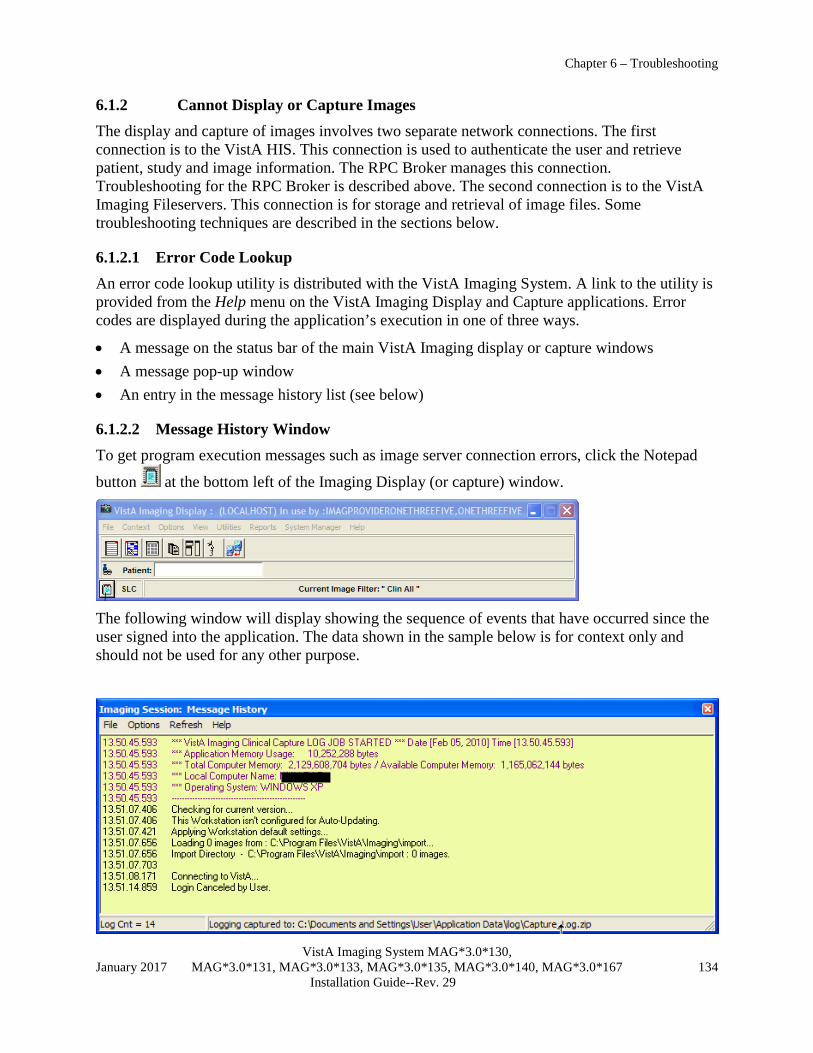
Chapter 6 – Troubleshooting
VistA Imaging System MAG*3.0*130, January 2017 MAG*3.0*131, MAG*3.0*133, MAG*3.0*135, MAG*3.0*140, MAG*3.0*167 134 Installation Guide--Rev. 29
6.1.2 Cannot Display or Capture Images The display and capture of images involves two separate network connections. The first connection is to the VistA HIS. This connection is used to authenticate the user and retrieve patient, study and image information. The RPC Broker manages this connection. Troubleshooting for the RPC Broker is described above. The second connection is to the VistA Imaging Fileservers. This connection is for storage and retrieval of image files. Some troubleshooting techniques are described in the sections below.
6.1.2.1 Error Code Lookup An error code lookup utility is distributed with the VistA Imaging System. A link to the utility is provided from the Help menu on the VistA Imaging Display and Capture applications. Error codes are displayed during the application’s execution in one of three ways.
• A message on the status bar of the main VistA Imaging display or capture windows • A message pop-up window • An entry in the message history list (see below)
6.1.2.2 Message History Window To get program execution messages such as image server connection errors, click the Notepad
button at the bottom left of the Imaging Display (or capture) window.
The following window will display showing the sequence of events that have occurred since the user signed into the application. The data shown in the sample below is for context only and should not be used for any other purpose.

Chapter 6 – Troubleshooting
VistA Imaging System MAG*3.0*130, January 2017 MAG*3.0*131, MAG*3.0*133, MAG*3.0*135, MAG*3.0*140, MAG*3.0*167 135 Installation Guide--Rev. 29
Note: System information such as path and file is only displayed for uses with the MAG SYSTEM security key. Users without this key are shown all other non-system messages. The Message History function is part of Clinical Capture, Clinical Display, and the TeleReader applications. Message History enables the following actions:
• | Options | System Messages | is an option to turn off the display of system messages in the Message History window. To access this option, the user must have the appropriate system security key.
• | Options | Find Text | is a feature that allows users to search the log display for words or word phrases.
• | Refresh | Refresh Display | refreshes the information layout that is displayed in the Message History window.
6.1.2.3 Image Information Sometimes it is helpful to get information on the image(s) that are not being displayed. In the abstract and group windows of Imaging Display, there is a pop-up menu option for getting image properties. When looking at an individual image abstract (not a group abstract), right-click on the abstract to get the context menu. Click Image Info to display the Image Information window.
The window below shows the image properties that are stored in the Image file (#2005). It also displays the internal entry number (IEN) of the image record.
To see additional image properties, use the Image Information. When looking at an individual image abstract (not a group abstract), right-click the abstract to get the context menu. Click Image Information Advanced to display the image properties window.
The following window shows the full path to the image file and other image properties that are stored in the Image file (#2005). It also displays the internal entry number (IEN) of the image record.

Chapter 6 – Troubleshooting
VistA Imaging System MAG*3.0*130, January 2017 MAG*3.0*131, MAG*3.0*133, MAG*3.0*135, MAG*3.0*140, MAG*3.0*167 136 Installation Guide--Rev. 29
The complete record can be displayed by pressing the button. Users can use the tool bar on the Image Information Advanced window to display image information for the next, previous, or groups of images. Image data such as time and date, image text, image information, and field values can be displayed by selecting the appropriate toolbar button.
A failure can also indicate that the username and password in the Imaging Site Parameters file (#2006.1) did not match the actual account username and password.
6.1.2.4 VistA Imaging Capture, Test Mode The VistA Imaging Capture software has a Test mode that allows testing of input devices (scanners, video capture boards, etc.). The Test mode features…
• Testing of the capture functions without a connection to the VistA servers
• No requirement to identify patients In addition, the image test file will not be saved. This mode is helpful when interfacing and testing new equipment.
To set the application to test mode, select Test Mode from the Configuration|Configuration Settings|mode…’ menu. (See right)

Chapter 6 – Troubleshooting
VistA Imaging System MAG*3.0*130, January 2017 MAG*3.0*131, MAG*3.0*133, MAG*3.0*135, MAG*3.0*140, MAG*3.0*167 137 Installation Guide--Rev. 29
6.1.3 Slowness when Displaying or Capturing Images Slowness problems are usually related to the network infrastructure in the Medical Center. Isolate the problem by copying a 10-megabyte file from the server to the workstation. As a general rule of thumb, it should take 3 seconds or less to copy the file on a 100MB network. It should take 6 seconds or less to copy the file on a 10MB network. If it takes longer than that, there is a basic network problem outside of the VistA Imaging application that must be resolved. Check to see that the server, the workstation and any switch that connects them are all set to full duplex. We have seen slowness occur when there is translation from full to half duplex and vice versa. Some switches are incapable of negotiating full duplex.
6.1.4 Other Helpful Hints
6.1.4.1 Editing the Network Location Operational Status Field
The Network Location file keeps track of whether the server it refers to is online or offline. This is very useful in case of a malfunction or scheduled repair on that server. The VistA Imaging software will check this field when retrieving files. If a unit is offline and there is a Tier 2 on the system, the image file will automatically be retrieved from Tier 2. If there is no Tier 2, the file will not be retrieved but the workstation will handle the situation gracefully. It will not hang trying to connect to an offline server.
To set a network location offline, select Edit|Network Location Manager from the Background Processor and un-check the Operational Status check box.

Chapter 6 – Troubleshooting
VistA Imaging System MAG*3.0*130, January 2017 MAG*3.0*131, MAG*3.0*133, MAG*3.0*135, MAG*3.0*140, MAG*3.0*167 138 Installation Guide--Rev. 29
Note: Checking the option labeled ‘Operational Status’ will place the network location on-line. If the option is cleared then the network location is off-line.
6.1.4.2 VistA HIS Software Troubleshooting VistA Imaging software relies heavily on APIs or report routines supplied by other VistA application package developers. These APIs are used to interface the VistA Imaging System with Medicine, Surgery, Radiology, CPRS, TIU and Laboratory. If problems arise regarding the API being used, the Imaging application may display an information message regarding this error or the error will be recorded in the VistA error trap routine. If any of these errors occur, please contact the VistA Imaging Customer Support team by logging a Remedy call.
The VistA Imaging application requires the “MAG WINDOWS” menu option assigned. The following message text will appear if a user does not have this menu option. . Also, the user will need either the “MAG DISP ADMIN” or “MAG DISP CLIN” security key, otherwise they will be denied access.
6.1.4.3 Other VistA Imaging Troubleshooting Information Review the manufacturer’s installation guide to find testing tools distributed with Imaging components such as scanners and capture boards. See the VistA Imaging System Technical Manual for additional troubleshooting guidelines.
6.1.5 QA Review Utility The Clinical Display Imaging Workstations have a QA Review function. This function allows authorized users to verify and change image status and index values. This functionality is available to all users who have either the MAG QA REVIEW, MAG EDIT or the MAG SYSTEM security key. The IMAGE file (#2005) – STATUS (#113) stores the image statuses.
Values for the IMAGE file (#2005) – STATUS (#113) are:
Viewable: All images will have a default status of Viewable, and images with no status (existing images) are viewable.
QA Reviewed: A user has viewed the image and verified that the patient and values for index fields are correct. The user changes the status to QA Reviewed.
In Progress: Image groups are being captured; addition of images to the group of images is not complete. Once the image group capture is complete, the status is automatically set to Viewable.
Needs Review: Indicates that values of the index fields or patient have been found to be incorrect. VistA Imaging Display will block images with this status from view. The Image Edit Utility is used to modify incorrect values of the index fields.
Section 2.3.4 explains the different security keys for users.

Chapter 6 – Troubleshooting
VistA Imaging System MAG*3.0*130, January 2017 MAG*3.0*131, MAG*3.0*133, MAG*3.0*135, MAG*3.0*140, MAG*3.0*167 139 Installation Guide--Rev. 29
6.1.6 QA Image Edit Utility The QA Image Index Utility is available only as a sub menu from the QA Review Utility. Users of this utility will be able to view and modify the indexes for a selected image. This functionality is available for all users who hold either the MAG EDIT or MAG SYSTEM security key.
Section 2.3.4 explains the different security keys for users.

Chapter 6 – Troubleshooting
VistA Imaging System MAG*3.0*130, January 2017 MAG*3.0*131, MAG*3.0*133, MAG*3.0*135, MAG*3.0*140, MAG*3.0*167 140 Installation Guide--Rev. 29
This page intentionally left blank.

Appendix A – Security
VistA Imaging System MAG*3.0*130, January 2017 MAG*3.0*131, MAG*3.0*133, MAG*3.0*135, MAG*3.0*140, MAG*3.0*167 141 Installation Guide--Rev. 29
Appendix A Security A.1 Workstation Security If configured properly, the VistA Imaging software will control user access to image files on the file server. Under Windows, the VistA Imaging software provides application-based protection for image files. This requires the application to have permissions to view and store images but denies individual user access to image files.
A.1.1 BIOS Changes The workstation BIOS should be password-protected to prevent users from changing the workstation settings. Some sites have reported that their users have modified the workstation BIOS and password-protected the BIOS, making it unavailable for IRM staff to fix.
A.1.2 Virus Protection The VA recommends VirusScan for virus protection on workstations and on VistA Imaging file servers. Contact IPRM for further details or visit its web site at https://vaww.infoprotection.va.gov/index.aspx.
A.1.3 Windows System Policies and Profiles For Windows-based systems, a site can limit access to files and options on the workstation by using system policies and profiles. For detailed information, refer to the documentation for the Windows version installed at your site.
A.1.4 Imaging Software If configured properly, the VistA Imaging software will connect automatically to the file server shares to store or retrieve images. The user who is logged into the workstation will not have access to those shares. The privileged username and password for the file server is retrieved by the VistA Imaging application from the VistA Imaging system.
e.g., The user logs into the workstation with their domain account (i.e. vha05\vhawassmithj). The VistA Imaging display application is executed. When the user requests images for a particular patient, the application makes a connection to the file server using its privileged username and password and retrieves the files it needs. It then disconnects from the file server.
Note: It is very important that this be configured correctly to ensure proper protection of patient confidentiality. Contact the VistA Imaging support team with any questions.
A.1.5 Physical Protection All systems should be physically locked to protect them from being stolen. Sites have reported many instances of equipment that has “disappeared” from its location.

Appendix A – Security
VistA Imaging System MAG*3.0*130, January 2017 MAG*3.0*131, MAG*3.0*133, MAG*3.0*135, MAG*3.0*140, MAG*3.0*167 142 Installation Guide--Rev. 29
A.1.6 Medical Center Policy Many medical centers have a strict policy for users that will have access to clinical workstations. Any user that will obtain access to the system must sign a form that states the policy for the site.
A.2 Windows Server Security Be sure to change the default passwords for the administrator, guest and anonymous user accounts. VistA Imaging users will not log into the VistA Imaging file servers; image files will be accessed only through shares.
A.2.1 Folder and Share Security Folder and share security is used to control access to the image files. If the system is configured properly, only the VistA Imaging application and the administrator (or equivalent) will have access to the folders and shares that contain images. All other users will not have access.
A.2.2 Hidden Shares Hidden shares are used for image folders on the VistA Imaging file server so they will not show up in the browse list of any client workstation.

Appendix B – Backups
VistA Imaging System MAG*3.0*130, January 2017 MAG*3.0*131, MAG*3.0*133, MAG*3.0*135, MAG*3.0*140, MAG*3.0*167 143 Installation Guide--Rev. 29
Appendix B Backups The VistA Imaging System software saves medical images as part of the patient’s electronic record. Because these medical images are part of a patient’s medical record they are protected by the Federal Privacy Act. As images are captured, they are stored on magnetic servers and immediately copied to Tier 2 servers by the Background Processor. This ensures that there are initially two copies of each image. At some point, the image files will be aged off of the Tier 1 servers and only one copy of each image will exist on the optical platters. Because of the possibility of an optical platter failure, a secondary backup of image files is necessary. There are currently two recommended methods for ensuring that two copies of each image always exist.
• Continuous incremental backup of the Tier 1 shares – An initial full backup of the image share is performed at the initial imaging installation and subsequent nightly incremental backups are performed. Tapes CANNOT be re-used! Periodic FULL backups should be done for each share in the event of a catastrophic loss of that share.
• Media Copy in the Disk Extender Tier 2 storage management software - The software can be configured to manually copy media after a platter has been filled or automatically fill copy media as original media is written to. This option requires the site to purchase additional media to be used as copy media. This may create additional expense at the onset, but can save on FTEE labor expense in the event that a restore is necessary. For additional information, refer to Appendix C. This is the recommended method. When this method is used, WORKING SET (backup of N days of created files) tape backups are necessary only when Tier 2 is unavailable and there are recent files on Tier 1 that have not been copied to Tier 2.
In addition to backing up the image shares, be sure to back up the DICOM gateway dictionary files and on the image servers, the folder containing the catalogs/data/job definitions for the tape backups. You may also want to backup your Queue Processor logs and Purge logs as well as Verifier logs for future reference in troubleshooting missing images.
The following table contains recommendations for backup strategy:
Media/Files Frequency Type Media Type
Comments
Image shares Periodic Full Tape In case of catastrophic loss of the share.
Image shares Daily Incremental Tape Only necessary if Media Copies are not being done on the platters and/or the Tier 2 is unavailable and recent images are on Tier 1 and not on Tier 2.
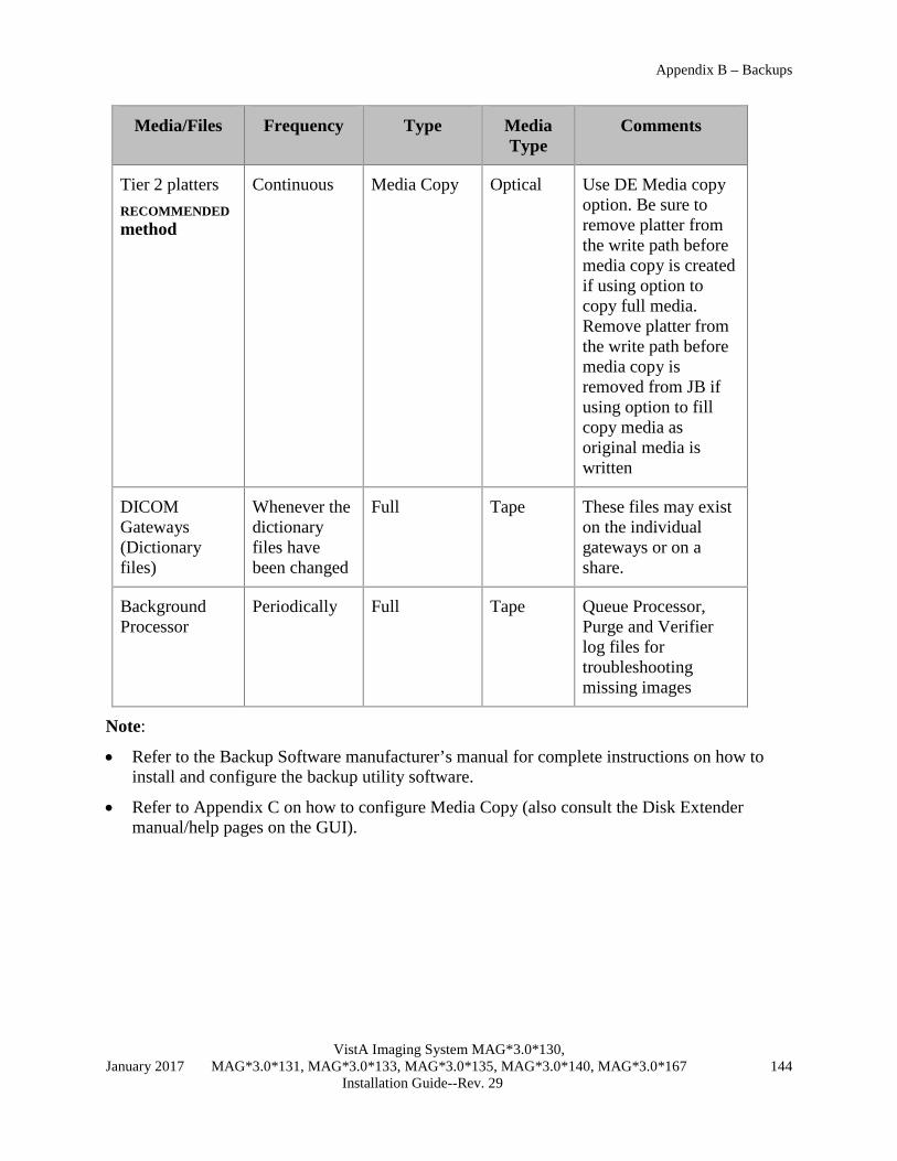
Appendix B – Backups
VistA Imaging System MAG*3.0*130, January 2017 MAG*3.0*131, MAG*3.0*133, MAG*3.0*135, MAG*3.0*140, MAG*3.0*167 144 Installation Guide--Rev. 29
Media/Files Frequency Type Media Type
Comments
Tier 2 platters RECOMMENDED method
Continuous Media Copy Optical Use DE Media copy option. Be sure to remove platter from the write path before media copy is created if using option to copy full media. Remove platter from the write path before media copy is removed from JB if using option to fill copy media as original media is written
DICOM Gateways (Dictionary files)
Whenever the dictionary files have been changed
Full Tape These files may exist on the individual gateways or on a share.
Background Processor
Periodically Full Tape Queue Processor, Purge and Verifier log files for troubleshooting missing images
Note:
• Refer to the Backup Software manufacturer’s manual for complete instructions on how to install and configure the backup utility software.
• Refer to Appendix C on how to configure Media Copy (also consult the Disk Extender manual/help pages on the GUI).

Appendix C - Using MediaStor and DiskXtender
VistA Imaging System MAG*3.0*130, January 2017 MAG*3.0*131, MAG*3.0*133, MAG*3.0*135, MAG*3.0*140, MAG*3.0*167 145 Installation Guide--Rev. 29
Appendix C Using MediaStor and DiskXtender This appendix explains how to perform the following Tier 2 maintenance tasks:
• Adding new media • Setting up new media for image storage • Creating media copies for backup purposes • Using compaction to shift to higher capacity media • Configuring server schedules • Configuring server alerts
Note: This appendix reflects the terminology used by MediaStor and DiskXtender, where media is generally equivalent to a single optical disc/platter. For details about other terms or for information about other procedures, refer to the online help for MediaStor and DiskXtender.
Note: All steps in this section assume that primary configuration of Tier 2 is complete.
C.1 Adding Media to Tier 2 The following sections explain how to use MediaStor to add media to Tier 2 and assign it to an application pool. Once media is assigned to the application pool, it can be accessed by DiskXtender.
C.1.1 Inserting Media 1. Launch MediaStor (Double-click the desktop shortcut, or click Start | Programs | Legato
MediaStor).
2. On the left side of the MediaStor Administrator window, select the Tier 2 entry for your site (located under the Hardware (library) node).
3. Right-click the Tier 2 entry and choose Manage Media.

Appendix C - Using MediaStor and DiskXtender
VistA Imaging System MAG*3.0*130, January 2017 MAG*3.0*131, MAG*3.0*133, MAG*3.0*135, MAG*3.0*140, MAG*3.0*167 146 Installation Guide--Rev. 29
4. In the dialog that opens, locate the empty shelves that you want to have the new media added to. Empty shelves are indicated by the value <EMPTY> in the Media Name column.
5. Select a shelf for each piece of media that you want to add.
• Each “A” and “B” entry is treated as a single shelf. • Use the SHIFT or the CTRL key with the mouse to select multiple shelves.
6. Click Insert.
7. In the Insert Library Media window, verify that the first option is selected and that it shows the shelves you want to use. Then click OK.
8. When you are prompted to do so, insert each piece of media, then click OK.
• If a mail slot is being used, you will be prompted for each piece of media. • If a magazine loader is being used, you will be prompted once.
9. After adding all the media, click Close to return to the main window.
• Once the media is processed, it will appear in the Blank area of the Scratch Pool node. • Before the media can be used, it must be added to the application pool. Then it must be
labeled and added to a move group. See the following sections for more information.
C.1.2 Adding Media to the Application Pool Newly inserted media will need to be added to an application pool before it can be accessed using DiskXtender. To add media to an application pool:
1. In the MediaStor Administrator window, locate and expand the Blank node under the Scratch Pool.

Appendix C - Using MediaStor and DiskXtender
VistA Imaging System MAG*3.0*130, January 2017 MAG*3.0*131, MAG*3.0*133, MAG*3.0*135, MAG*3.0*140, MAG*3.0*167 147 Installation Guide--Rev. 29
2. In the upper right part of the window, select each piece of media that you want to allocate
(you can drag to select multiple items).
3. Right-click and choose Allocate Media to Application Pool.
4. In the dialog that displays, use the Application Media Pools box to select the media pool you want to use.
5. Click Allocate, then click OK.

Appendix C - Using MediaStor and DiskXtender
VistA Imaging System MAG*3.0*130, January 2017 MAG*3.0*131, MAG*3.0*133, MAG*3.0*135, MAG*3.0*140, MAG*3.0*167 148 Installation Guide--Rev. 29
6. After the media has been processed, it will appear in the Blank area under the Application Pool node that you selected.
7. At this point, you can use DiskXtender do one of the following with the media:
• Set up media for image storage (see section C.2).
• Create a media copy using the new media (see section C.3).
• Compact pre-existing media onto the new media (see section C.4).
C.2 Setting up New Media for Image Storage Blank media added using MediaStor can be labeled and assigned to a media folder using DiskXtender. After media has been labeled and assigned, the media will need to be added to a move group as described in the next section.
C.2.1 Labeling & Assigning Media 1. Launch DiskXtender (double-click the desktop shortcut, or click Start | Programs | Legato
DiskXtender).
2. On the left site of the DiskXtender Administrator window, locate the Media area under the Available Media node (you may need to expand the Available media node).
3. Right-click the blank media you want to label and click Edit Tasks.
4. In the Media Tasks dialog that displays, perform the following steps:

Appendix C - Using MediaStor and DiskXtender
VistA Imaging System MAG*3.0*130, January 2017 MAG*3.0*131, MAG*3.0*133, MAG*3.0*135, MAG*3.0*140, MAG*3.0*167 149 Installation Guide--Rev. 29
a. In the Next Task box located near the bottom of the dialog, verify that LABEL is displayed, then click Add New Task.
b. The Next Task box will automatically display the ADD TO MEDIA FOLDER task. Click Add New Task. Both tasks should now appear in the top of the Media Tasks dialog.
c. Select the Label task.
d. On the right side of the dialog, enter the media name you want to use for the selected media.
e. Indicate if you want the media to be labeled immediately or according to your site’s server schedule.
f. Select the Add To Media Folder task.
g. On the right side of the dialog, verify that the proper media folder is selected.
Note: Most sites will have only one folder. For sites with more than one folder, select the folder that is defined in the Background Processor as the current write location.

Appendix C - Using MediaStor and DiskXtender
VistA Imaging System MAG*3.0*130, January 2017 MAG*3.0*131, MAG*3.0*133, MAG*3.0*135, MAG*3.0*140, MAG*3.0*167 150 Installation Guide--Rev. 29
h. Indicate if you want the task to be performed immediately or according to your site’s server schedule.
i. Click Next.
j. In the dialog that displays, verify that the tasks appear as desired, then click Finish.
5. The media you selected for labeling and addition to a media folder will be shown in green until it is processed.
6. Once the media is labeled and assigned, the media will appear in the Media node of the folder you selected. The media can now be added to a move group as described in the next section.

Appendix C - Using MediaStor and DiskXtender
VistA Imaging System MAG*3.0*130, January 2017 MAG*3.0*131, MAG*3.0*133, MAG*3.0*135, MAG*3.0*140, MAG*3.0*167 151 Installation Guide--Rev. 29
C.2.2 Adding Media to the Move Group
Once media has been labeled and assigned to a media drive (as described above), the media can be added to a move group.
1. In the DiskXtender Administrator window, locate the move group that you want to add the media to. Typically, the move group will be named JB1 to Optical.
2. Right-click the appropriate move group and select Properties.
3. In the dialog that displays, click the Media tab, then click Add.
4. The Select Move Group Media dialog will display. Select the media you want to add (you can drag the mouse to select multiple entries)
5. Click OK to close the selection dialog, then click OK again to close the Move Group
Properties dialog and to apply your changes.

Appendix C - Using MediaStor and DiskXtender
VistA Imaging System MAG*3.0*130, January 2017 MAG*3.0*131, MAG*3.0*133, MAG*3.0*135, MAG*3.0*140, MAG*3.0*167 152 Installation Guide--Rev. 29
6. You can verify that the media is present in the move group by right-clicking the move group, clicking Properties, and then clicking the Media tab.
C.3 Using Media Copy for Backups This section explains how to create a copy of a Tier 2 platter and how to replace an original platter with a copied platter.
These steps are intended for sites that want to use media copies (instead of other methods) to meet backup requirements.
Note: Media copies of platters being used as backups need to be stored offsite.
C.3.1 Making a Media Copy 1. In the DiskXtender Administrator window, verify that there is blank, unlabeled media present
to be designated as copies. (See sections C.1.1 and C.1.2 for information about adding blank media).

Appendix C - Using MediaStor and DiskXtender
VistA Imaging System MAG*3.0*130, January 2017 MAG*3.0*131, MAG*3.0*133, MAG*3.0*135, MAG*3.0*140, MAG*3.0*167 153 Installation Guide--Rev. 29
2. Select the media you want to create a media copy of and verify that the media is full.
3. If the selected media is still part of the move group, remove it using the following steps:
a. Right-click the move group and choose Properties.
b. In the dialog that appears, click the Media tab.
c. If the media is in the list, select the media and click Remove. Then click OK to close the properties dialog and apply your changes.
4. In the main DiskXtender window, click Tools | Copy Media Manager.
5. At the bottom of the dialog, click Label New Copy Media.
6. In the Label Copy Media dialog, select the first option, then click Next.
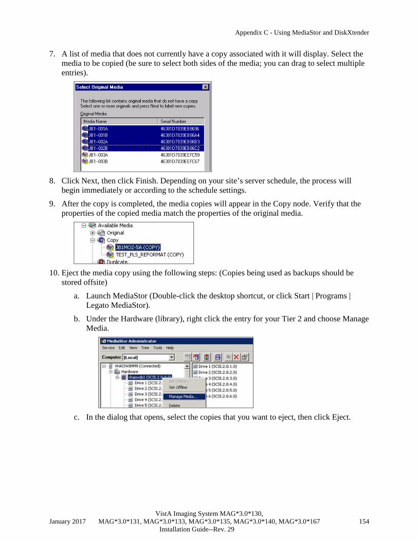
Appendix C - Using MediaStor and DiskXtender
VistA Imaging System MAG*3.0*130, January 2017 MAG*3.0*131, MAG*3.0*133, MAG*3.0*135, MAG*3.0*140, MAG*3.0*167 154 Installation Guide--Rev. 29
7. A list of media that does not currently have a copy associated with it will display. Select the media to be copied (be sure to select both sides of the media; you can drag to select multiple entries).
8. Click Next, then click Finish. Depending on your site’s server schedule, the process will
begin immediately or according to the schedule settings.
9. After the copy is completed, the media copies will appear in the Copy node. Verify that the properties of the copied media match the properties of the original media.
10. Eject the media copy using the following steps: (Copies being used as backups should be
stored offsite)
a. Launch MediaStor (Double-click the desktop shortcut, or click Start | Programs | Legato MediaStor).
b. Under the Hardware (library), right click the entry for your Tier 2 and choose Manage Media.
c. In the dialog that opens, select the copies that you want to eject, then click Eject.

Appendix C - Using MediaStor and DiskXtender
VistA Imaging System MAG*3.0*130, January 2017 MAG*3.0*131, MAG*3.0*133, MAG*3.0*135, MAG*3.0*140, MAG*3.0*167 155 Installation Guide--Rev. 29
11. When the media copy is ejected, verify that it is offline (displayed in brown) in DiskXtender.
C.3.2 Removing Original Media If an original piece of media becomes unreadable, it can be removed as described below:
1. In the DiskXtender Administrator window, right click the “Side A” of the media to be removed and click Remove.

Appendix C - Using MediaStor and DiskXtender
VistA Imaging System MAG*3.0*130, January 2017 MAG*3.0*131, MAG*3.0*133, MAG*3.0*135, MAG*3.0*140, MAG*3.0*167 156 Installation Guide--Rev. 29
2. In the dialog that displays, verify that the first option (Delete files from extended drive...) is selected, then click Next.
3. Click Finish.
4. When you are prompted to perform a drive scan, click NO.
5. Repeat steps 1 - 3 above for “Side B” of the media you want to remove.
6. When you are prompted to perform a drive scan, click Yes.
• As the drive scan proceeds, the media you selected for removal is shown in green.
• Once the media is offline, it will be removed from the media folder and will appear in the Available Media tree under Original.
7. In the Original node, right-click the platters to be removed and click Deallocate.
8. Eject the media using the following steps:
a. Launch MediaStor (Double-click the desktop shortcut, or click Start | Programs | Legato MediaStor).
b. Under the Hardware (library), right click the entry for your Tier 2 and choose Manage Media.
c. In the dialog that opens, media that you want to eject, then click Eject.
C.3.3 Promoting Copy Media The following steps explain how to insert a pre-existing media copy and how to promote it to original status.
Note: Once a copy has been promoted to original, it must remain as an original. Attempting to demote the copy and return the original back to the system is not supported and may result in data loss.
1. Use MediaStor to insert the media copy as described below:
a. Launch MediaStor (Double-click the desktop shortcut, or click Start | Programs | Legato MediaStor).

Appendix C - Using MediaStor and DiskXtender
VistA Imaging System MAG*3.0*130, January 2017 MAG*3.0*131, MAG*3.0*133, MAG*3.0*135, MAG*3.0*140, MAG*3.0*167 157 Installation Guide--Rev. 29
b. Under the Hardware (library), right click the entry for your Tier 2 jukebox and choose Manage Media.
c. In the dialog that opens, select the empty shelves that you want to have the new media added to.
d. Click Insert.
e. In the Insert Library Media window, verify that the first option is selected and that it shows the shelves you want to use. Then click OK.
f. When you are prompted to do so, insert the copy media, then click OK.
g. After adding all the media, click Close to return to the main window.
2. In DiskXtender, click Tools | Copy Media Manager.
3. In the dialog that displays, select the copy media to be promoted (be sure to select both sides of the media).
4. Click Promote Copy To Original.

Appendix C - Using MediaStor and DiskXtender
VistA Imaging System MAG*3.0*130, January 2017 MAG*3.0*131, MAG*3.0*133, MAG*3.0*135, MAG*3.0*140, MAG*3.0*167 158 Installation Guide--Rev. 29
C.4 Using Platter Compaction to Migrate to High-capacity Media Platter compactions can be performed to help free up physical platter space and to reduce the number of platters needed for archiving images. You can also use platter compaction to transfer data from smaller capacity media to larger capacity media.
Note: When using platter compaction as a part of migrating to a new Tier 2, make sure that the destination platter size is supported by the new Tier 2 (for example, most Plasmon jukeboxes cannot read platters less than 5.1 GB in size).
C.4.1 Performing Platter Compactions Note: The steps in this section assume that multiple media folders are available. Contact Customer Support for information about performing compactions using a single media folder/move group.
1. Verify that the extended drive that will be used during the compaction process has enough free space to accommodate images from the media being compacted.
2. Verify that destination platters of the desired capacity are in the move group associated with the media folder to be compacted.
3. In the media folder to be compacted, right-click on media to be compacted and select Edit Tasks.
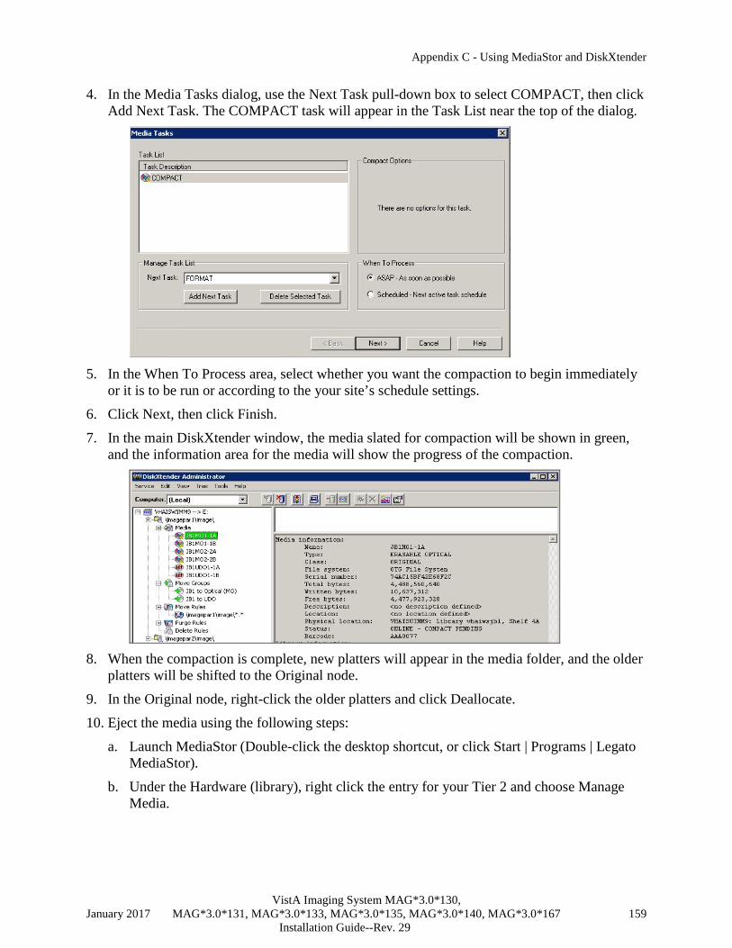
Appendix C - Using MediaStor and DiskXtender
VistA Imaging System MAG*3.0*130, January 2017 MAG*3.0*131, MAG*3.0*133, MAG*3.0*135, MAG*3.0*140, MAG*3.0*167 159 Installation Guide--Rev. 29
4. In the Media Tasks dialog, use the Next Task pull-down box to select COMPACT, then click Add Next Task. The COMPACT task will appear in the Task List near the top of the dialog.
5. In the When To Process area, select whether you want the compaction to begin immediately
or it is to be run or according to the your site’s schedule settings.
6. Click Next, then click Finish.
7. In the main DiskXtender window, the media slated for compaction will be shown in green, and the information area for the media will show the progress of the compaction.
8. When the compaction is complete, new platters will appear in the media folder, and the older
platters will be shifted to the Original node.
9. In the Original node, right-click the older platters and click Deallocate.
10. Eject the media using the following steps:
a. Launch MediaStor (Double-click the desktop shortcut, or click Start | Programs | Legato MediaStor).
b. Under the Hardware (library), right click the entry for your Tier 2 and choose Manage Media.

Appendix C - Using MediaStor and DiskXtender
VistA Imaging System MAG*3.0*130, January 2017 MAG*3.0*131, MAG*3.0*133, MAG*3.0*135, MAG*3.0*140, MAG*3.0*167 160 Installation Guide--Rev. 29
c. In the dialog that opens, select the media that you want to eject, then click Eject.
C.5 Configure Server Schedules This section explains how to specify which DiskXtender processes are performed immediately and which are performed at a scheduled time.
1. In the DiskXtender Administrator window, right-click the extended drive, then click Properties.
2. In the dialog that displays, click the Settings tab, then click Schedule.

Appendix C - Using MediaStor and DiskXtender
VistA Imaging System MAG*3.0*130, January 2017 MAG*3.0*131, MAG*3.0*133, MAG*3.0*135, MAG*3.0*140, MAG*3.0*167 161 Installation Guide--Rev. 29
3. The dialog that displays shows the current schedule settings for the four primary activities performed by DiskXtender.
4. For each activity, use the controls in the dialog to set when each activity is to occur.
Suggested settings are listed below (adjust as needed to conform to site policies):
• Move files to media: 12 AM to 12 PM.
• Process scheduled media tasks: 12 AM to 12 PM.
• Update copy media: 12 AM to 5 AM.
• Allow fetches from media: 12 AM to 12 PM. 5. Click OK to apply your changes and close the dialog.
C.6 Configure Server Alerts Use the following steps to specify the how warning and error notifications are handled.
1. In the DiskXtender Administrator window , click Service | Properties.
2. Click the Alerts tab.
Note: If you are planning on sending email-alerts, enter the name of your STMP server in the Mail Server box in the near the bottom of the dialog.
3. Click the Add button.

Appendix C - Using MediaStor and DiskXtender
VistA Imaging System MAG*3.0*130, January 2017 MAG*3.0*131, MAG*3.0*133, MAG*3.0*135, MAG*3.0*140, MAG*3.0*167 162 Installation Guide--Rev. 29
4. In the Type box, indicate if the notifications will be sent to a computer, a domain, an email account, or to a user.
5. In the Send To box, enter or change the computer name, domain name, e-mail address, or
username that the notifications will be addressed to.
6. Use the checkboxes to indicate if error and/or warning notifications will be sent.
7. When you are finished, click Add to close the Alert Settings dialog, then click OK to close the Service Properties dialog.

Appendix C - Using MediaStor and DiskXtender
VistA Imaging System MAG*3.0*130, January 2017 MAG*3.0*131, MAG*3.0*133, MAG*3.0*135, MAG*3.0*140, MAG*3.0*167 163 Installation Guide--Rev. 29
Appendix D Setting Parameter Values Site administrators can use a set of parameter definitions to set user or group permissions. These parameters provide the flexibility to grant and deny various permissions at the site.
Annotation Parameters Example By default, all users can view annotations, but they cannot annotate images. Site administrators can use the following parameter definitions to give users permission to add annotations to images. Only users with the MAG ANNOTATE MGR key have the ability to add, edit, and delete annotations.
To set up annotation permission, access the MAG IMAGE ALLOW ANNOTATE parameter definition through the VistA menu option [XPAR EDIT PARAMETER].
The following shows an example of how to set up the parameter definition for the Cardiology service. Select OPTION NAME: XPAR EDIT PARAMETER Edit Parameter Values --- Edit Parameter Values --- Select PARAMETER DEFINITION NAME: MAG IMAGE ALLOW ANNOTATE MAG IMAGE ALLOW ANNOTATE MAG IMAGE ALLOW ANNOTATE may be set for the following: 1 User USR [choose from NEW PERSON] 2 Service SRV [choose from SERVICE/SECTION] 3 Division DIV [choose from INSTITUTION] 4 System SYS [IMGDEM01.MED.VA.GOV] Enter selection: SERV Service SERVICE/SECTION Select SERVICE/SECTION NAME: CARD 1 CARDIOLOGY 111A MEDICINE 2 CARDIOLOGY MEDICINE 111 CHOOSE 1-2: 1 CARDIOLOGY 111A MEDICINE --------- Setting MAG IMAGE ALLOW ANNOTATE for Service: CARDIOLOGY --------- Value: ? Allow User, Service, Division or System to annotate the image. Value: YES

VistA Imaging System MAG*3.0*130, January 2017 131, MAG*3.0*133, MAG*3.0*135, MAG*3.0*140, MAG*3.0*167 164 Installation Guide--Rev. 29
This page intentionally left blank.
VistA Imaging System MAG*3.0*130, January 2017 131, MAG*3.0*133, MAG*3.0*135, MAG*3.0*140, MAG*3.0*167 165 Installation Guide--Rev. 29
Index
3
3D display software, integrating VistARad with, 89
A
accounts, 12 adding media to a move group, 151 Advanced Web Image Viewer, 1 Advanced Web Image Viewer Web
Application, 1 alerts, setting up in DiskXtender, 162 application pool, 145 AWIV Web Application, 69, 70
B
Background Processor functions, 20 installation instructions, 21 Purge parameters, 29
Broker client installation, 34, 133
C
Capture, integrating image sources with, 119 Clinical Imaging, installing, 35
remote push, 39, 41 single workstation, 35
compacting media, 158 CPRS interface, 60 Current Namespace field, 29
D
dictation software, integrating VistARad with, 88
DiskXtender, 144
F
file server naming conventions, 11
permissions, 13 security, 13
film digitizers, 130 folder permissions, 13 frame grabbing
supported boards, 120 using Capture for, 119
I
IA account, 12 Image file (#2005)., 135 Image Information window, 135 image sources, integrating with Capture, 119 Imaging file server
naming conventions, 11 permissions, 13
Imaging Site Parameter file (#2006.1), 27 Imaging software, installing, 35 Imaging System components, 1 inserting media, 144 installation, VistARad, 73 installing Clinical Imaging, 35
remote push, 39, 41 single workstation, 35
IU account, 12
K
KIDS installation, 15
L
labeling media, 148
M
MAG WINDOWS menu option, 19, 138 MAG.ini, 36, 37 MAG308.INI configuration summary, 42 MAG308.INI editor, using, 42 MAG308.INI sections, 44 MagInstall.exe, 35, 39 MagInstallPush.bat, 39

Index
VistA Imaging System MAG*3.0*130, January 2017 MAG*3.0*131, MAG*3.0*133, MAG*3.0*135, MAG*3.0*140, MAG*3.0*167 166 Installation Guide--Rev. 29
MAGJ.INI, 85 MAGSYS, 42 mail group, 29 Matrox drivers
configuring, 121 installing, 120 removing, 123
Matrox frame grab boards, 120 media
adding to a move group, 151 compacting, 158 copying for backup purposes, 152 inserting, 144 labeling, 148 promoting, 157 removing original, 156
MediaStor, 144 MediaStor and DiskXtender software, 30 Medicine package, 53 Message History window, 134 MIL installation, 120 move groups, adding media to, 151 MUSE
error codes, 59 installing, 57 naming conventions, 57 Users group, 58 Workstation Settings, 58
N
naming conventions Imaging file server, 11 MUSE, 57
Network Location file (#2005.2) image storage locations, 26 Jukebox location definition, 30 setting locations offline, 137
O
optical disk. See media original media, removing, 156
P
package requirements, 5 permissions, folder and share, 13 platter. See media
promoting media, 157 PSExec, using for remote pushes, 39
R
Radiology package, testing, 53 requirements
approved components, 6 contractors' services, 6 identifying locations, 7 network topology, 8 staff, 6
RPC Broker client installation, 34, 133
RPC Broker client, 34, 81 RPCTest, 34, 133
S
scanned documents, 129 scanners, 54, 130 schedules, setting up in DiskXtender, 161 securing workstations, 131 security keys
for Clinical Display and Capture, 19 for Imaging mail group, 29 for VistARad, 94
security, file server, 13 Sentillion Vergence Desktop, 82 server
naming conventions, 11 permissions, 13
server alerts, setting up in DiskXtender, 162 setup.msi, 41 share permissions, 13 SMS, using for remote push installation, 41 still digital cameras, 128
T
testing Clinical Imaging, 52 Medicine package, 53 Radiology package, 53 scanners, 54 VistARad, 116
training mode (VistARad), 116 troubleshooting, 133 TWAIN interface, 129

Index
VistA Imaging System MAG*3.0*130, January 2017 MAG*3.0*131, MAG*3.0*133, MAG*3.0*135, MAG*3.0*140, MAG*3.0*167 167 Installation Guide--Rev. 29
U
UDO (Ultra Dense Optical) media, 158 user accounts, 12
V
video capture boards, supported, 120 video image inputs for Capture, 119 video output, integrating with Capture, 124 virus protection software, 13, 140 VistA System
configuring for VistARad, 93 VistARad
3D integration, 89 approved programs, 80 display settings, 76 driver setup guidelines, 75 installation overview, 73 overview, 3
required software, 80 testing, 116 testing installation of, 115 VistA System configuration for, 93 voice dictation integration, 88 workstation setup, 73
VIX (VistA Image Exchange) service, 3
W
worklist.txt, 39 workstation
Imaging, 2 placement, 4 security, 131 VistARad, 3
workstation setup for VistARad, 73
X
X-ray film digitizer interface, 130