vistar - textfiles.com layout - the vistar keyboard includes a model 33 teletype compatible...
TRANSCRIPT
VISTAR
TECHNICAL USER'S MANUAL
INFOTON, INC. C. KEN r RIPLEY P. U. S:>x 6611
f.
'San Jose, CA. 95150======':"1 (408) 31/-61
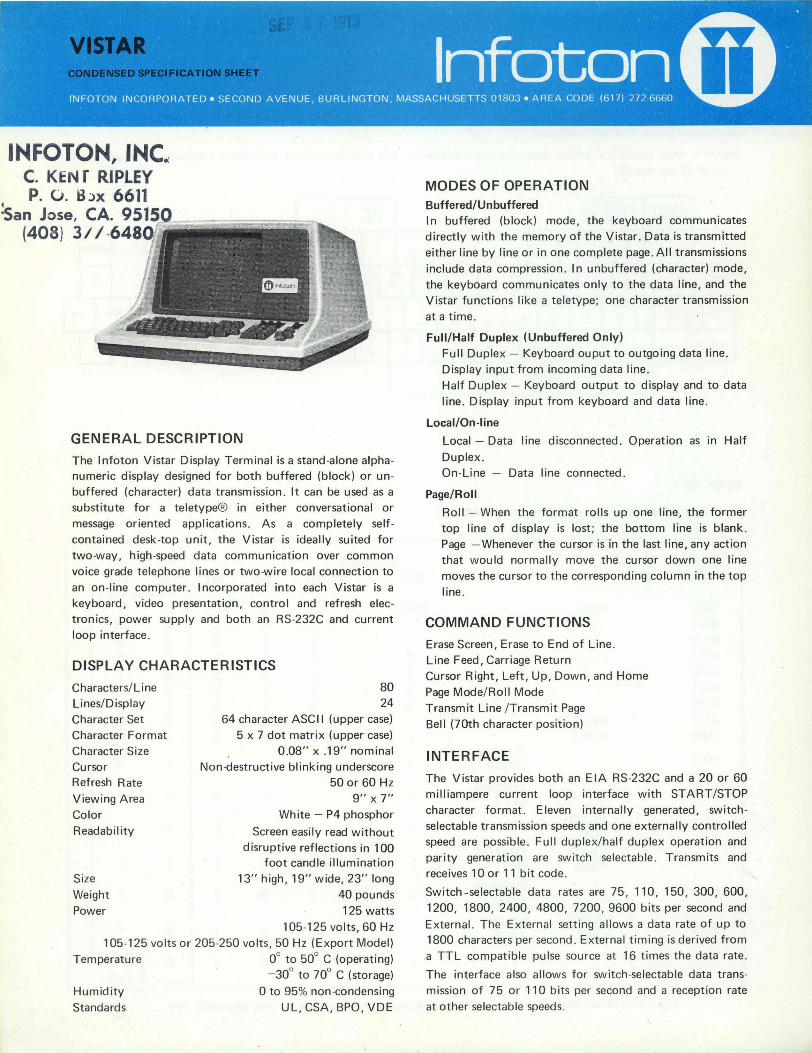
GENERAL DESCRIPTION
The Infoton Vistar Display Terminal is a stand-alone alphanumeric display designed for both buffered (block) or unbuffered (character) data transmission . It can be used as a
substitute for a teletype@ in either conversational or
message oriented applications . As a completely self
contained desk-top unit, the Vistar is ideally suited for
two-way, high-speed data communication over common
voice grade telephone lines or two-wire local connection to
an on -line computer . Incorporated into each Vistar is a
keyboard, video presentation, control and refresh elec
tronics, power supply and both an RS-232C and current loop interface .
DISPLAY CHARACTERISTICS
Characters/ Line Lines/Display Character Set Character Format
Character Size
Cursor Refresh Rate
Viewing Area
Color
Readability
80 24
64 character ASCII (upper case)
5 x 7 dot matrix (upper case)
0.08" x .19" nominal
Non-<lestructive blinking underscore
50 or 60 Hz 9" x 7"
White - P4 phosphor
Screen easily read without
disruptive reflections in 100 foot candle illumination
Size
Weight
Power
13" high, 19" wide, 23" long
40 pounds
125 watts
105·125 volts , 60 Hz
105-125 vol t s or 205-250 volts, 50 Hz (Export Model)
Temperature 0° to 50° C (operating) - 30° to 70° C (storage)
Humidity
Standards
o to 95% non -condensing
UL, CSA, BPO , VDE
MODES OF OPERATION Buffered/Unbuffered In buffered (block) mode, the keyboard communicates directly with the memory of the Vistar. Data is transmitted
either line by line or in one complete page. All transmissions
include data compression. In unbuffered (character) mode,
the keyboard communicates only to the data line, and the Vistar functions like a teletype; one character transmission
at a time .
Full/Half Duplex (Unbuffered Only) Full Duplex - Keyboard ouput to outgoing data line.
Display input from incoming data line. Half Duplex - Keyboard output to display and to data
line. Display input from keyboard and data line.
Local/On-line
Local - Data line disconnected . Operation as in Half
Duplex. On-Line - Data line connected.
Page/Roll
Roll - When the format rolls up one line, the former top line of display is lost; the bottom line is blank.
Page - Whenever the cursor is in the last line, any action
that would normally move the cursor down one line
moves the cursor to the corresponding column in the top
line.
COMMAND FUNCTIONS
Erase Screen, Erase to End of Line .
Line Feed, Carriage Return
Cursor Right, Left, Up, Down, and Home
Page Mode/ Roll Mode
Transmit Line /Transmit Page
Bell (70th character position)
INTERFACE
The Vistar provides both an E IA RS-232C and a 20 or 60
milliampere current loop interface with START/STOP
character format. Eleven internally generated, switch
selectable t ransmission speeds and one externally controlled speed are possible . Full duplex/half duplex operation and
parity generation are switch selectable . Transmits and
receives 10 or 11 bit code.
Switch - selectable data rates are 75, 11 0, 150, 300, 600,
1200, 1800, 2400, 4800, 7200,9600 bits per second and
External. The External setting allows a data rate of up to 1800 characters per second . External timing is derived from
a TTL compatible pulse source at 16 times the data rate .
The interface also allows for switch-selectable data trans
mission of 75 or 110 bits per second and a reception rate
at other selectable speeds.
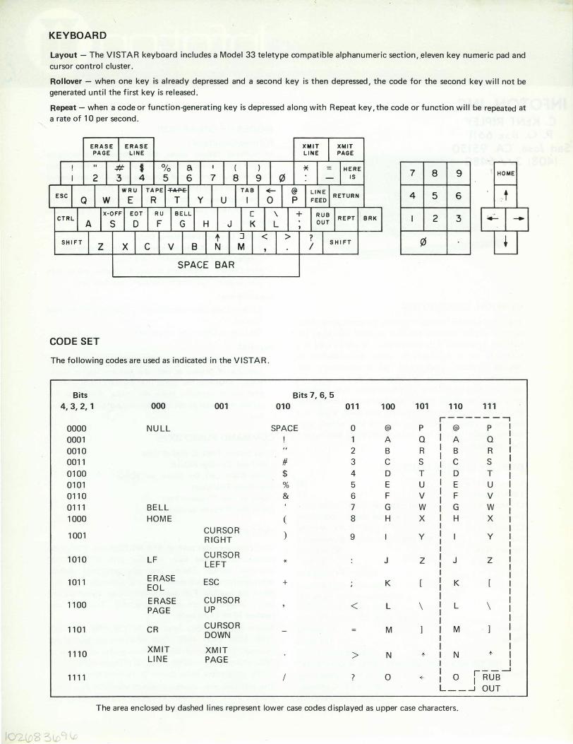
KEYBOARD
Layout - The VISTAR keyboard includes a Model 33 teletype compatible alphanumeric section, .eleven key numeric pad and cursor control cluster .
Rollover - when one key is already depressed and a second key is then depressed, the code for the second key will not be generated until the first key is released .
Repeat - when a code or function·generating key is depressed along with Repeat key, the code or function will be repeated at a rate of 10 per second .
7 8 9 HOME
4 5 6 .. t
I 2 3
(t1
SPACE BAR
CODE SET
The following codes are used as indicated in the VISTAR .
Bits Bits 7, 6, 5 4,3,2,1 000 001 010 011 100 101 110 111
r----- --, 0000 NULL SPACE 0 @ P @ P
0001 1 A Q A Q
0010 2 B R B R 0011 # 3 C S C S
0100 $ 4 D T D T 0101 % 5 E U E U 0110 & 6 F V F V
0111 BELL 7 G W G W
1000 HOME ( 8 H X H X
1001 CURSOR ) RIGHT 9 Y y
1010 LF CURSOR
J Z J Z LEFT *
1011 ERASE ESC + K K EOL
1100 ERASE CURSOR < L \ L \ PAGE UP
1101 CR CURSOR M M DOWN
1110 XMIT XMIT > N N + LINE PAGE
+
1111 / ? 0 + o jRUB-I L __ .....J OUT
The area enclosed by dashed lines represent lower case codes displayed as upper case characters.
Ie L\C8::)lL. . \t..

r
INFOTON INCORPORATED • SECOND AVENUE, BURLINGTON, MASSACHUSETTS 01803 • AREA CODE 617 272·6660 SUBSIDIARY OF OPTICAL SCANNING CORPORA TION
Document No. 02327 October/1972
VISTAR
TECHNICAL USER'S MANUAL

INFOTON INCORPORATED • SECOND AVENUE, BURLINGTON, MASSACHUSETTS 01803 • AREA CODE 617 272·6660 SUBSIDIARY OF OPTICAL SCANNING CORPORA TlON
ii
1.
2.
3.
4.
5.
INFOTON INCORPORATED • SECOND AVENUE, BURLINGTON, MASSACHUSETTS 01803 • AREA CODE 617 272·6660 SUBSIDIARY OF OPTICAL SCANNING CORPORATION
INFOTON
TECHNICAL USER'S MANUAL
VISTAR
TABLE OF CONTENTS
INTRODUCTION
SUMMARY OF CHARACTERISTICS I nterchangeable with Teletype Easy-to- Read Characters High-Speed Transmission Rates Choice of Computer Interface Roll or Page Mode Cursor Control Erase Page and Erase to End of Line Transmission Modes Print Mode Detached Keyboard Model
VISTAR SPECIFICATIONS Screen Format Mechanical Environmental Controls, Switches and Connectors Electrical Standards
FUNCTIONAL DESCRIPTION Local/On Line Character Mode Block Operation
OPERATIONAL FEATURES Teletypewriter Compatibility Cursor Roll Mode Page Mode Response to Commands Erase Screen Erase to End of Line Bell Carriage Retu rn Line Feed Null
iii
Page No.
1
3 3 3 3 3 3 3 3 3 3 3
5 5 5 5 5 6 6
7 7 7 7
9 9 9 9 10 10 10 10 10 10 10 11
INFOTON INCORPORATED • SECOND AVENUE, BURLINGTON, MASSACHUSETTS 01803 • AREA CODE 617 272·6660 SUBSIDIARY OF OPTICAL SCANNING CORPORA TlON
TABLE OF CONTENTS - Continued
5. OPERATIONAL FEATURES (CONT.) Break
6.
7.
8.
9.
Rubout Home Cursor Controls Transmit Line Transmit Page
EQUIPMENT DESCRIPTION Keyboard Display Control Logic Controls
INTERFACE Introduction Asynchronous Serial Interface Wiring of Current Loop Interface
COMPATIBILITY WITH OTHER INFOTON VISTAR SERIES DISPLAY TERMINALS
OPERATING INSTRUCTIONS Initial Setup Establish Communication
Appendix A - VISTAR Code Set
Appendix B - V I STAR I nput-Output Codes
Appendix C - Multipurpose Asynchronous Serial Interface EIA Signals and Pin Connections
LIST OF FIGURES
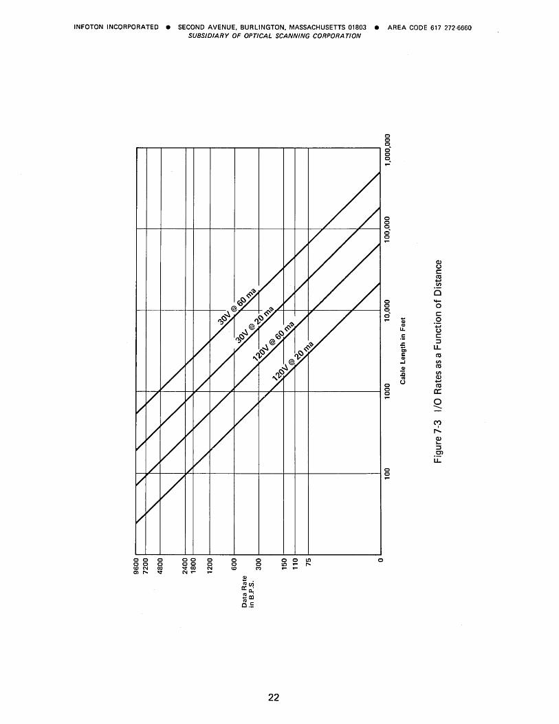
Figure 1-1. VISTAR Display Terminal Figure 6-1. VISTAR Keyboard Figure 6-2. Dot Matrix Character Format Figure 6-3. Dot Matrix with Cursor Figure 6-4. Location of TV Controls on VISTAR Figure 7-1. VISTAR Interface Panel Figure 7-2. Wiring to VISTAR Current Loop Terminal Strip Figure 7-3. I/O Rates as a Function of Distance
iv
Page No.
11 11 11 11 11 11
13 13 14 14 16
17 17 17 20
23
25 25 25
27
29
33
Page No.
1 13 15 15 16 18 21 22
INFOTON INCORPORATED • SECOND AVENUE. BURLINGTON. MASSACHUSETTS 01803 • AREA CODE 617 272·6660 SUBSIDIARY OF OPTICAL SCANNING CORPORA TlON
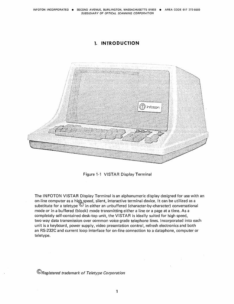
1. INTRODUCTION
Figure 1-1 VISTAR Display Terminal
The INFOTON VISTAR Display Terminal is an alphanumeric display designed for use with an on-line computer as a hig~speed, silent, interactive terminal device. It can be utilized as a substitute for a teletype <9 in either an unbuffered (character-by-character) conversational mode or in a buffered (block) mode transmitting either a line or a page at a time. As a completely self-contained desk-top unit, the VISTAR is ideally suited for high speed, two way data transmission over common voice grade telephone lines. I ncorporated into each unit is a keyboard, power supply, video presentation control, refresh electronics and both an RS-232C and current loop interface for on-line connection to a dataphone, computer or teletype.
©Registered trademark of Teletype Corporation

INFOTON INCORPORATED • SECOND AVENUE, BURL.INGTON, MASSACHUSETTS 01803 • AREA CODE 617 272-6660 SUBSIDIARY OF OPTICAL SCANNING CORPORA TION
r .. ~, ,
2
INFOTON INCORPORATED • SECOND AVENUE, BURLINGTON, MASSACHUSETTS 01803 • AREA CODE 617 272-6660 SUBSIDIARY OF OPTICAL SCANNING CORPORATION
2. SUMMARY OF CHARACTERISTICS
INTERCHANGEABLE WITH TELETYPE
The VISTAR can be substituted for a Model 33 or 35 teletype with no hardware or software modifications. The VISTAR can serve as an upgraded high speed terminal to all time-sharing services using ASCII * Code regardless of the computer system used by the service.
EASY-TO-READ CHARACTERS
High resolution, non-reflecting screen, and contrast-enhancing filter permit easy viewing at distances up to 10 feet under direct glare and 100 foot-candle illumination.
HIGH-SPEED TRANSMISSION RATES
Eleven switch-selectable transmission rates from 75 to 9600 bits per second are provided.
CHOICE OF COMPUTER INTERFACE
The unit is supplied with two forms of asynchronous serial interfaces; i.e., a standard E IA RS-232C interface and a 20 or 60 ma TTY style current loop.
ROLL OR PAGE MODE
The VISTAR may be operated in either Roll or Page Mode, depending upon the position of a convenient front panel switch.
CURSOR CONTROL
The unit has a non-destructive position marker or cursor displayed as a blinking underscore. The cursor position can be tracked and manipulated by the computer or the operator to any position on the screen.
ERASE PAGE AND ERASE TO END OF LINE
The full screen may be erased with one command. With another command, the unit will erase all characters from the cursor position to the end of the line in which the cursor resides.
TRANSMISSION MODES
The VISTAR may operate either in a character-by-character transmission mode, exactly as a teletype, or in Block Mode, in which data is not sent until a transmit command is generated. The choice of modes is made by a convenient front panel switch.
PRINT MODE
The V ISTAR offers a simple two-wire connection to an external peripheral device such as a printer or tape cassette. Data transmission to such a peripheral is determined by the Xmit/ Print control switch located on the front panel.
DETACHED KEYBOARD MODEL
The V ISTAR is also available with a detachable keyboard that is separately packaged and connected to the display by a flexible cable.
* American Standard Code for Information Interchange.
3

INFOTON INCORPORATED • SECOND AVENUE, BURLINGTON, MASSACHUSETTS 01803 • AREA CODE 617 272·6660 SUBSIDIARY OF OPTICAL SCANNING CORPORA TION
4
INFOTON INCORPORATED • SECOND AVENUE, BURLINGTON, MASSACHUSETTS 01803 • AREA CODE 617 272·6660 SUBSIDIARY OF OPTICAL SCANNING CORPORA TION
3. VISTAR SPECIFICATIONS
SCREEN FORMAT
Characters per line Lines per display Character set Character format Character size Refresh rate Viewing area Color Readability
MECHANICAL
Size Weight
ENVIRONMENTAL
Operating temperature Storage temperature Humidity
80 24 64 character ASCII upper case 5 x 7 dot matrix 0.08 inch x 0.19 inch, nominal 50 Hz or 60 Hz 9 inches x 7 inches White - P4 phosphor Screen easily read without disruptive reflections in a 100-foot illumination.
13 inches high, 19 inches wide, 23 inches deep 40 pounds
0° to 50°C -30° to 70°C o to 95% non-condensing
CONTROLS, SWITCHES AND CONNECTORS
Front Side Rear Internal
On/Off Switch X Local/On Line Switch X Roll/Page Switch X Character/Block Transmission X Xmit/Print Switch X TV InJensity X TV Horizontal X TV Vertical X Received Data Rate Selector X Transmitted Data Rate Selector X Full/Half Duplex Switch X 10/11 B it Code Switch X Automatic Carriage Return Switch X Odd/Even/Mark Parity Switch X Current Loop Wiring Strip X EIA Connector X External Video Jack X 115/230 Volt Wiring Connections X 50/60 Hz Refresh Switch X
5
INFOTON INCORPORATED • SECOND AVENUE, BURLINGTON, MASSACHUSETTS 01803 • AREA CODE 617 272·6660 SUBSIDIARY OF OPTICAL SCANNING CORPORA TlON
ELECTRICAL
Power consumption Domestic power Export power
STANDARDS Underwriter's Laboratory
125 watts 105 - 125 volts; 60 Hz 105 - 125, 205 - 250 volts; 50 Hz
Export models will conform to requirements established by British Post Office Telecommunications Headquarters, the standards of the Verein Deutscher E lektrotechniker (VD E), and the Canadian Standards Association (CSA).
6
INFOTON INCORPORATED • SECOND AVENUE, BURLINGTON, MASSACHUSETTS 01803 • AREA CODE 617 272·6660 SUBSIDIARY OF OPTICAL SCANNING CORPORA TION
4. FUNCTIONAL DESCRIPTION
The VISTAR Display Terminal is a completely self-contained desk top unit which can be used as a plug-for-plug replacement for a teletype. The unit consists of a keyboard, video monitor, refresh memory, control logic, and serial data interface. The modes of operation and communications are described in the following paragraphs.
LOCAL/ON LINE
In LOCAL, the VISTAR is disconnected from the data line but is functional in all other respects. The LOCAL position is used only for demonstration and testing purposes. The LOCAL/ON LINE selection is made by a switch on the front panel of the terminal.
The remainder of this description refers to various types of ON LI N E operation.
CHARACTER MODE
In the Character Mode, the keyboard communicates only to the interface transmitter, and only the interface receiver communicates to the display memory. All transmissions are on a character-by-character basis. All codes generated by the keyboard, including control or function codes, go directly to the transmitter and then to the data lines.
When in Character Mode, the VISTAR may be placed in full or half duplex. In half duplex, the interface receiver is actuated in series with the transmitter, and transmitted codes are routed back through the receiver and displayed. Control codes either perform their specific function (e.g., BELL, CURSOR RIGHT, etc.) or are ignored.
In full duplex, the receiver is independent of the transmitter. Only data received from the data line will appear on the display. As in half duplex, control codes either perform their specific function or are ignored. I n full duplex, therefore, information will be displayed only if the computer at the end of the data line echoes back the information transmitted from the keyboard.
BLOCK OPERATION
In Block Mode, the keyboard communicates directly to the memory of the VISTAR. Function or control codes are stored in the memory only if they are generated in conjunction with the depression of the CONTROL key. For example, the CURSOR UP code does not go into memory unless both the CURSOR UP key and the CONTROL key are simultaneously depressed (Cursor Up will also be stored if generated by simultaneous depression of the CONTROL, SHIFT, and L keys). Control codes in memory are displayed by a non-blinking underscore and the equivalent alphanumeric character or symbol.
After a message has been entered from the keyboard, the operator may initiate a transmission by simultaneously depressing the SH I FT key and either the Transmit Line or Transmit Page key.
All transmissions include data compression. A series of SPACE characters completing a line will be ignored whenever the Transm it Line or Transmit Page function is executed. I n the case of Transmit Page, the transmission proceeds immediately to the next line after data compression; hence the operator is required to insert his own control code(s) at the end of line in order to divide the page into lines and prevent word packing.
A switch on the rear panel is available to automatically insert a Carriage Return at the end of each transmission in the Block Mode.
7
INFOTON INCORPORATED • SECOND AVENUE, BURLINGTON, MASSACHUSETTS 01803 • AREA CODE 617 272·6660 SUBSIDIARY OF OPTICAL SCANNING CORPORATION
Depression of the BREAK key places' a space condition on the data line and terminates any transmission in progress. Detection of a BREAK condition by the receiver also terminates any transmission in progress.
In Block Mode, data received from the data line is presented directly to the display. However during transmission from the display, the receiver is disabled (except for detecting BREAK). Control codes received from the data line cause their associated function to occur and are not stored in memory.
8
INFOTON INCORPORATED • SECOND AVENUE, BURLINGTON, MASSACHUSETTS 01803 • AREA CODE 617 272·6660 SUBSIDIARY OF OPTICAL SCANNING CORPORA TlON
5. OPERATIONAL FEATURES
TELETYPEWRITER COMPATIBILITY
The VISTAR reacts to the full ASCII character set (see Appendix A) receiving and storing both upper and lower case codes. For this reason, the VISTAR can be used without software modification in applications now using a Model 33 or 35 teletypewriter. The effect of each ASCII code on the VISTAR is shown in Appendix B. All characters are displayed as upper case characters. Lower case characters received on the data line are stored in memory and may be retransmitted, but will display as upper case characters. Although the terminal may be programmed as a teletypewriter, the full advantages of the VISTAR as an interactive terminal are realized when the software makes full use of the unit's features described in the following sections:
CURSOR
The cursor indicates the position at which the next data character will be displayed. The Home position for the cursor is the first position on the first line of the display; i.e., the upper left corner of the display.
The cursor appears on the display screen as a blinking underscore. It blinks approximately five times a second. The blinking prevents the operator from losing track of the cursor. The cursor will advance one step for each character that is typed. The cursor can be positioned by the cur~or control keys or from the data line. There are five cursor movement commands and corresponding keys, namely, Home, Cursor Down, Cursor Up, Cursor Left, Cursor Right. The Carriage Return and Line Feed codes also generate cursor movements. These commands allow the operator or the computer to manipulate the cursor to any position on the screen.
The cursor is "non-destructive'.' I n response to one of the cursor movement commands, the cursor moves but does not alter any data appearing on the screen.
The actual position of the cursor cannot be directly read by the computer. However, since all cursor movements entered by the operator via the keyboard are transmitted to the computer in the Character Mode, the computer can at all times follow the position of the cursor. This feature allows software editing on a page of textual data on the screen.
The computer can move the cursor to any X-V coordinate by including the appropriate sequence of cursor movement Characters in a message being sent to the VISTAR. An efficient cursor moving algorithm can be constructed by using the "wrap-around" feature of the cursor movement at the edges of the screen. For example, the computer program or operator can move the cursor from the Home position to the lower right corner with a single Cursor-Left command.
ROLL MODE
The VISTAR is placed in Roll Mode by the setting of a switch on the front panel. When the screen fills, in Roll Mode, the data on the screen rolls up one line; the former top line is lost and the bottom line is blank. As line after line of text is written on the screen, the visual effect is that of a continuous scroll of test moving past a window.
Rolling is caused when the cursor is anywhere on the bottom line and a LINE FEED character is received by the terminal. Rolling is also caused when the cursor is in the bottom right corner of the screen and any displaying code including SPACE is received.
Cursor movement from one of the five basic cursor com mands (Home, Cursor Righi, Cursor Left, Cursor Up,and Cursor Down) will not cause a roll. When the cursor is in the
9
INFOTON INCORPORATED • SECOND AVENUE, BURLINGTON, MASSACHUSETTS 01803 • AREA CODE 617 272"6660 SUBSIDIARY OF OPTICAL SCANNING CORPORA TION
bottom line, Cursor-Down moves the cursor to the top line without rolling. From the bottom right position Cursor-R ight moves the cursor to the top left position without rolling. This prevents inadvertent rolling during cursor manipulation by the operator.
The VISTAR has been designed so that no restrictions are placed on the high speed transfer of data in the roll mode. Data will not be lost even at 9600 bits per second.
PAGE MODE
I n Page Mode any action that wou Id otherwise cause the data to roll resu Its in new data to be written over old data on the top line of the screen.
RESPONSE TO COMMANDS
The VISTAR terminal is controlled and manipulated from its data stream. The data stream control logic is defined as follows:
1. Certain characters are designated as command characters (Appendix B). 2. The computer inserts these command characters within the text trans
mitted to the VISTAR. 3. The VISTAR continually monitors the input data stream for these
command characters, performing a designated action upon reception of a command character.
For example, when an Erase to End of Line command character is received by the VISTAR, the unit erases all characters from and including the cursor position to the end of line (the cursor does not move), and then examines the next character in the data stream to determine what action is to be taken.
A description of the commands used to control the display follows.
ERASE SCREEN
All data on the screen is erased. Cursor moves to Home position.
ERASE TO END OF LINE
BELL
Erases all data from, and including, the cursor position to the end of line. The cursor does not move. When a memory location is erased, a SPACE code is stored in that position rather than a" NULL code.
The bell will sound for the following conditions: A. Receipt of the Bell Code (Control G) from the data line. B. Block Mode - The introduction of the 70th character on a line from the keyboard.
The bell will not sound if a Bell Code is being transmitted from memory, nor if the cursor moves into the 70th position while the display is received or transmitting data.
C. Character Mode - The movement of the cursor into the 70th position on a line.
CARRIAGE RETURN
Places the cursor in left-most position of the line in which the cursor resides.
LINE FEED,
Moves the cursor down one line. I n Roll Mode',; causes rolling when the cursor is on the bottom line. I n Page Mode, moves the cursor from the bottom line to the top line.
To prevent inadvertent double spacing of lines with exactly 80 characters, the VISTAR has
10
INFOTON INCORPORATED • SECOND AVENUE, BURLINGTON, MASSACHUSETTS 01803 • AREA CODE 617 272·6660 SUBSIDIARY OF OPTICAL SCANNING CORPORA TlON
NULL
been equipped with a feature which inhibits Line Feed after line wrap-around. Line wraparound occurs when a displaying code, Cursor Right code, or SPACE code causes the cursor to advance automatically from the 80th character position to the first character position of the next line. Following line wrap-around, the VISTAR will ignore a Line Feed until a character is put into memory or a second Line Feed is received.
No action is taken when this code appears on the data line. This code is generated from the keyboard by "Control Shift P".
BREAK
Depressing the break key forces a "space" condition on the data line as long as the key is depressed. Detecting a "Break" Code terminates any Transmit function when in Block Mode.
RUBOUT
HOME
Causes a rubout code (all one bits) to be transmitted. In Character Mode, no cursor movements occur and no character enters memory. In B lock Mode, depression of the rubout key causes the rubout code to be entered into memory, displaying the parity error block.
Places the cursor in the first character position of the first line.
CURSOR RIGHT
Places the cursor one position to the right of its present position. If the cursor is in the last character of line, the next position is first position in the line below, or in the Home position if the cursor is in the last line.
CURSOR LEFT
Places the cursor one position to the left of its present position. If the cursor is in the first character of line, the next position is the last position of the line above, or in the bottom right position on the screen if the cursor is in the Home position.
CURSOR UP
Places the cursor one line above its present position. If the cursor is in the first line, the next position is in the corresponding position of the bottom line.
CURSOR DOWN
Places the cursor one line below its present position. If the cursor is in the laOst line, the next position is the corresponding position in the top line.
TRANSMIT LINE
The cursor returns to the beginning of the line it is in and the terminal transmits the entire line. After transmission, the cursor returns to the beginning of the line transmitted.
TRANSMIT PAGE
The cursor moves to the Home position, and the entire page is transmitted. After transmission, the cursor returns to the beginning of the bottom line.
11
INFOTON INCORPORATED • SECOND AVENUE, BURLINGTON, MASSACHUSETTS 01803 • AREA CODE 617 272·6660 SUBSIDIARY OF OPTICAL SCANNING CORPORA TION
'.,
12
INFOTON INCORPORATED • SECOND AVENUE, BURLINGTON, MASSACHUSETTS 01803 • AREA CODE 617 272·6660 SUBSIDIARY OF OPTICAL SCANNING CORPORA TlON
6. EQUIPMENT DESCRIPTION
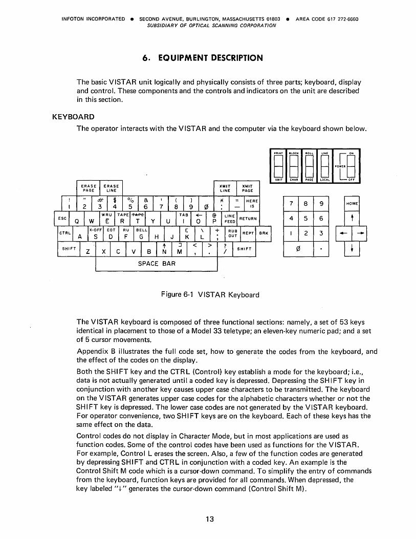
The basic VISTAR unit logically and physically consists of three parts; keyboard, display and control. These components and the controls and indicators on the unit are described in this section.
KEYBOARD
The operator interacts with the V ISTAR and the computer via the keyboard shown below.
PRI .. T BLOCK ROLL LINE I 0 ..
8 8 8 8 ,,",,8 OIiT CHAR PAGE LOCAL LJ OFF
7 8 9 HOME
4 5 6
I 2 3
!l1
SPACE BAR
Figure 6-1 VISTAR Keyboard
The VISTAR keyboard is composed of three functional sections: namely, a set of 53 keys identical in placement to those of a Model 33 teletype; an eleven-key numeric pad; and a set of 5 cursor movements.
Appendix B illustrates the full code set, how to generate the codes from the keyboard, and the effect of the codes on the display.
Both the SHI FT key and the CTR L (Control) key establish a mode for the keyboard; i.e., data is not actually generated until a coded key is depressed. Depressing the SH I FT key in conjunction with another key causes upper case characters to be transmitted. The keyboard on the V 1ST AR generates upper case codes for the alphabetic characters whether or not the SH I FT key is depressed. The lower case codes are not generated by the VISTAR keyboard. For operator convenience, two SH I FT keys are on the keyboard. Each of these keys has the same effect on the data.
Control codes do not display in Character Mode, but in most applications are used as function codes. Some of the control codes have been used as functions for the VISTAR. For example, Control L erases the screen. Also, a few of the function codes are generated by depressing SHIFT and CTRL in conjunction with a coded key. An example is the Control Shift M code which is a cursor-down command. To simplify the entry of commands from the keyboard, function keys are provided for all commands. When depressed, the key labeled" t" generates the cursor-down command (Control Shift M).
13
INFOTON INCORPORATED • SECOND AVENUE, BURLINGTON, MASSACHUSETTS 01803 • AREA CODE 617 272·6660 SUBSIDIARY OF OPTICAL SCANNING CORPORA TlON
I n the Block Mode, the depression of the Control key disables control functions and allows the insertion of control codes into memory. When a control code goes into memory, it is displayed by the equivalent alphanumeric character or symbol and a non-blinking underscore.
The HERE IS key is inoperative since no answerback function is offered for the VISTAR.
The REPEAT key when depressed in conjunction with a coded key or function key generates repeated transmission of the code or function at a rate of 10 characters per second.
The BREAK key places "space"; i.e., a 10gical"Q" condition, on the data line for as long as the key is depressed. The BREAK key terminates any transmit function when in Block Mode.
The keyboard has an interlock feature and a roll-over feature which govern operation when two coded keys are simultaneously depressed.
When one key is depressed and a second key is subsequently depressed, the code for the second key will not be generated until the first key is released. No codes are generated if two or more keys are depressed simultaneously.
The keyboard is locked out when the beginning of a character on the data line is detected. No keyboard strobe can be generated until the received character is completed. This feature prevents the keyboard from garbling received characters.
DISPLAY
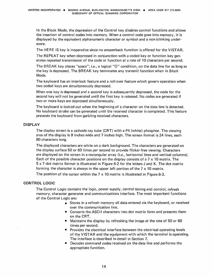
The display screen is a cathode ray tube (CRT) with a P4 (white) phosphor. The viewing area of the display is 9 inches wide and 7 inches high. The screen format is 24 lines, each 80 characters long.
The displayed characters are white on a dark background. The characters are generated on the display surface 50 or 60 times per second to provide flicker-free viewing. Characters are displayed on the screen in a rectangular array (i.e., horizontal lines and vertical columns). Each of the possible character positions on the display consists of a 7 x 10 matrix. The 5 x 7 dot matrix format is illustrated in Figure 6-2 for the letters J and K. The dot matrix forming the character is always in the upper left portion of the 7 x 10 matrix.
The position of the cursor within the 7 x 10 matrix is illustrated in Figure 6-3.
CONTROL LOGIC
The Control Logic contains the logic, power supply, central timing and control, refresh memory, character generator and communications interface. The most important functions of the Control Logic are:
• Stores in a refresh memory all data entered via the keyboard, or received over the communication line.
• Converts the ASCII characters into dot matrix form and presents them on the CRT.
• Maintains the display by refreshing the image at the rate of 50 or 60 times per second.
• Provides the electrical interface between the electrical operating levels of t~_~ ,VISTAR andthe equipment with which the terminal is operating. The interface is descr"ibec(in detail in Section 7.
• Decodes command codes received on the data line and performs the appropriate function.
14
INFOTON INCORPORATED • SECOND AVENUE, BURLINGTON, MASSACHUSETTS 01803 • AREA CODE 617 272·6660 SUBSIDIARY OF OPTICAL SCANNING CORPORA TlON
+ + + + + + + +.+ + + +.+ + + + + + + +:+ + +.+ + +.+ + + + + + + + +.+ + + + + + + + + + + + + + +.+ + +:+.+.+ + + + + +.+ + + +.+ + +.+ +.+ + + + + +.+ + + +.+ + +.+ + +.+ + + + + +.+.+.+ + + +.+ + + +.+ + + +++++++++++++++ +++++++++++++++ +++++++++++++++ +++++++++++++++
Figure 6-2 Dot Matrix Character Format
+ + + + +.+ + +.+ + + +.+ + + + + + + +.+ + +.+ + +.+ + + + + + + + +.+ + +.+ +.+ + + + + + + + + +.+ + +.+.+ + + + + + +.+ + + +.+ + +.+ +.+ + + + + +.+ + + +.+ + +.+ + +.+ + + + + +.+.+.+ + + +.+ + + +.+ + + +++++++++++++++ + + + + +- + + + + + + + + + +
CURSOR~+ + + + + + + + + + + + + + + +++++++++++++++
Figure 6-3 Dot Matrix with Cursor
15

INFOTON INCORPORATED • SECOND AVENUE, BURLINGTON, MASSACHUSETTS 01803 • AREA CODE 617 272·6660 SUBSIDIARY OF OPTICAL SCANNING CORPORA TlON
CONTROLS
The following five operator controls are located on the front panel, in the plane of the keyboard:
• ON/OFF Switch - In the OFF position, power is not connected to the terminal. I n the ON position the term inal is in the operating state. After the switch is turned to ON, a 3D-second warm-up period is required. A light, built into the switch, glows when the switch is in the ON position.
• LOCAL/ON LI NE Switch - This switch determines whether the terminal is disconnected from the data line (LOCAL) or connected to the data line (ON LI NE).
• ROLL/PAGE Switch - This switch selects between Roll Mode and Page Mode operation.
• CHAR/B LOCK Switch - This switch determines whether the terminal transmits only when a Transmit command is generated (B LOCK), or whether each code is transmitted whenever its key is depressed (CHAR).
• XMIT/PRINT - This switch determines whether data will be transmitted to the data line (XMIT) or to a peripheral output device such as a printer or tape cassette (P R I NT).
The three controls which govern the video presentation of characters are placed on the side of the unit to the operator's left. The I NTENSITY knob permits the brightness of the screen tobe set for the operator's comfort. The HO R I ZONT A L and V E RTI CA L controls allow adjustment for a stable picture. They correspond to the controls normally found on a commercial television receiver. Once these controls are set, they require infrequent adjustment.
The placement of the TV controls is shown in Figure 6-4 below.
HORZ VERT CONTRAST
L-HOLO---.J
Figure 6-4 Location of TV controls on VISTAR (Side View of VISTAR)
16
I 'I
1
, o.
INFOTON INCORPORATED • SECOND AVENUE, BURLINGTON, MASSACHUSETTS 01803 • AREA CODE 617 272-6660 SUBSIDIARY OF OPTICAL SCANNING CORPORA TlON
7. INTERFACE
INTRODUCTION
The V 1ST AR operates with a computer over either telephone lines (via a modem) or on local connection by direct cable. The single interface accommodates a wide range of computer systems and a wide range of data rates. This has been accomplished by adhering to commonly accepted standards for data transmission mode, transmission method (asynchronous) and transmission rate. There are no restrictions imposed by data rate limits upon any of the command codes of the VIST AR. Thus cursor movement commands, erase commands, etc., may be executed at the maximum rate at which the terminal can accept ordinary displaying codes. The I nterface Module makes the necessary conversion between the electrical operating levels of the VISTAR and those of the external circuit or computer with which the Interface Module is designed to operate. Also, the interface arranges data in the format required by the circuit or computer.
ASYNCHRONOUS SERIAL INTERFACE
The VISTAR communicates in a bit-serial, character asynchronous mode. The term asynchronous is synonymous with START-STOP and implies that the receiver comes to rest between characters. The START bit allows the receiving device to initiate its timing in proper synchronism with the incoming data. The STOP bit(s) ensure that the communication line is returned to the mark condition ready for a new START.
Transmitted data characters contain 10 or 11 bits, depending on the setting of a switch. (The Model 33 and 35 Teletype terminals transmit 11-bit code.) I n receiving, the V 1ST AR will operate with 10 or 11-bit formats. It is customary to use an 11-bit formatat 110 baud or below, and 10 bits at higher speeds, but the VISTAR is completely flexible both in transmission and reception.
The following bit configuration and character structure is used by the Asynchronous I nterface:
Bit: 1. START - "space" polarity - first bit transmitted
2. b 1 - least significant data bit 3. b 2 - data bit 4. b 3 - data bit 5. b 4 - data bit 6. b 5 - data bit 7. b6-databit 8. b 7 - most significant data bit 9. Parity bit
10. STOP - "mark" polarity 11. STOP - "mark" polarity (note comments above on 11th bit).
When the interface is transmitting, it adds the start bit, computes and adds the parity bit, and adds the stop bit to every seven-bit code being sent. When it is receiving, it removes the start and stop bits, and transfers only the seven information bits to the appropriate logic.
When receiving, parity is checked. A code with incorrect parity is replaced by the RUBOUT code and displayed as a solid block on the 5 x 7 matrix.
Transm ission is always in itiated with the start bit. Bits b 1 through b 7, shown above, bear a one-to-one correspondence with the bits b 1 through b 7 of the ASCII code (reference
17
INFOTON INCORPORATED • SECOND AVENUE, BURLINGTON, MASSACHUSETTS 01803 • AREA CODE 617 272-6660 SUBSIDIARY OF OPTICAL SCANNING CORPORATION
Appendix B). The "Space" and the "Mark" polarities are as defined by the E IA Standard RS-232C. * Even parity implies that the total number of ones in every character should be an even number; odd implies that it should be odd. Mark parity means that the parity bit is a Iways set to 1.
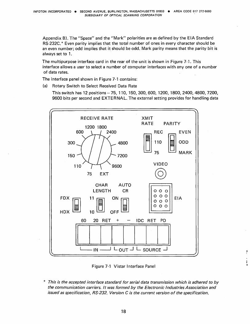
The multipurpose interface card in the rear of the unit is shown in Figure 7-1. This interface allows a user to select a number of computer interfaces with anyone of a number of data rates.
The interface panel shown in Figure 7-1 contains:
(a) Rotary Switch to Select Received Data Rate
This switch has 12 positions -- 75, 110, 150, 300, 600, 1200, 1800, 2400, 4800, 7200, 9600 bits per second and EXTERNAL. The external setting provides for handling data
RECEIVE RATE
1200 1800
XMIT RATE PARITY
600 2400
300 4800
150 7200
FDX
HDX
75 EXT
CHAR AUTO LENGTH CR
~ ::~ o::~
VIDEO
@ 000 000 000 000
60 20 RET + IDC RET PD
II I I I I I I I II ~ IN -----1 LOUT --.J L SOURCE -1
Figure 7-1 Vistar Interface Panel
EVEN
ODD
MARK
EIA
* This is the accepted interface standard for serial data transmission which is adhered to by the communication carriers. It was formed by the Electronic Industries Association and issued as specification, RS-232. Version C is the current version of the specification.
18
INFOTON INCORPORATED • SECOND AVENUE, BURLINGTON, MASSACHUSETTS 01803 • AREA CODE 617 272·6660 SUBSIDIARY OF OPTICAL SCANNING CORPORA TlON
rates other than the 11 fixed rates enumerated. The external clock must be a TTL compatible pulse source cycling at 16 times the data rate (maximum data rate is 1800 char/second) .
(b) Slide Switch to Select Transmitted Data Rate
The three positions on this switch are labeled 75,110, and RECEIVER. In the RECEIVER position, data will be transmitted at the rate determined by the rotary switch. The 75 and 110 baud positions permit a lower transmission data rate than the selected reception rate. Common dual speed rates in current use are 75/1200 and 110/2400. where the first and second figures are the transmission and reception rates, respectively.
(c) Slide Switch to Select 10 or 11 Bit Code
The setting of this two-position slide switch determines whether transmitted characters contain 10 bits (i.e., one STOP bit) or 11 bits (two STOP bits).
(d) Full Duplex/Half Duplex Switch
This two-position slide switch determines whether the terminal is operating in full duplex or half duplex. The position of this switch is of significance only when the terminal is in the Character Mode, as determined by the front panel switch. I n the Block Mode, the setting of the full duplex/half duplex switch is immaterial.
(e) Automatic Carriage Return Switch
This two-position slide switch determines whether or not a Carriage Return code will be automatically transmitted at the end of each block transmission. Its position is immaterial in Character Mode.
(f) Parity Selection Switch
This three-position slide switch allows the selection of odd, even, or mark parity (in the Mark position, received parity is ignored).
(g) Current Loop Wiring Strip
Depending upon the wiring to the terminal strip connector screws, the current loop interface will be 20 or 60 milliamperes, full or half duplex. (The wiring also determines full duplex/half duplex operation in the current loop interface; the slide switch is significant only for the EIA interface and should be in the FDX position when operating current loop.)
(h) Printer Output
A pair of connector screws are provided which, when the Xmit/Print switch is in the PR INT position, supply a 20 milliamperes drive signal operated from the transmit logic. The switch in the PR I NT position performs the following functions:
1. Routes transmitted data to the printer output. 2. Clamps the transmitter data line outputs in a marking condition. 3. Forces the unit into B LOCK mode.
The data rate selector switches must be in positions compatible with the driven device.
(0 EIA Connector
This MOLEX connector attaches to a cable supplied with the terminal. This cable is terminated with a 25-pin. connector equivalent to Cannon DB-19604-432 or to the Cinch Jones and Cannon DB-25P. I n Appendix C, the pin connections for both the MOLEX and the 25.-pin connectors are specified.
19
INFOTON INCORPORATED • SECOND AVENUE, BURLINGTON, MASSACHUSETTS 01803 • AREA CODE 617 272·6660 SUBSIDIARY OF OPTICAL SCANNING CORPORA TlON
(j) External Video Jack
A video jack provides a composite video signal, to allow connection of a remote monitor at a distance of up to 100 feet.
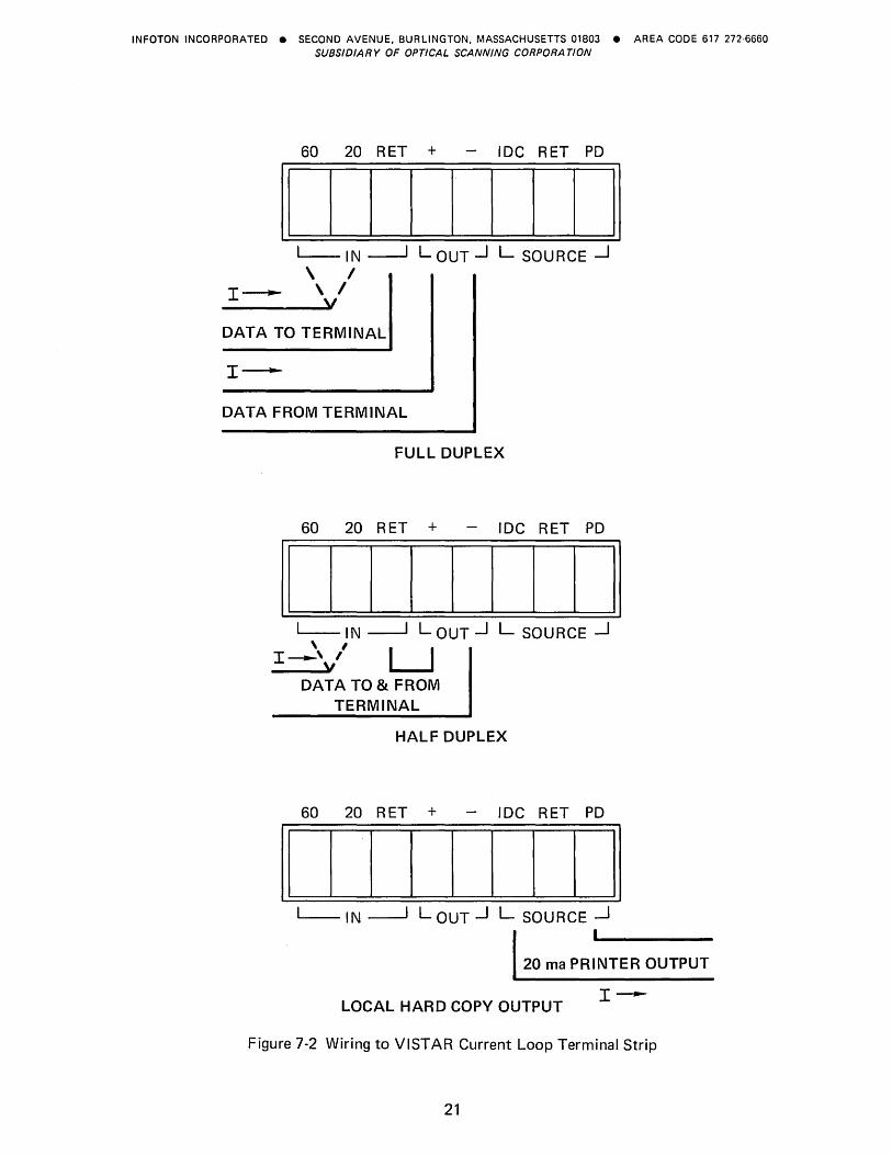
WIRING OF CURRENT LOOP INTERFACE
Full duplex and half duplex operation and 20 or 60 milliampere operation are determined by wiring. Figure 7-2 illustrates the wiring for the various modes of operation. Also illustrated is how an internal current source can be used in half duplex mode. Two-wire or four-wire twisted pairs are recommended for half or full duplex, respectively.
Over limited distances (less than 250 feet) it is preferable to use a true current source input to the interface so that voltage drops in the circuit and line do not affect the signal current.
For driving long lines (greater than 250 feet), a simple voltage-resistor driving source may be used. Figure 7-3 shows the maximum data rates as a function of cable length for two voltages and two currents.
When the VISTAR is connected to the data line by the EIA RS-232C interface, the current loop output is also available for transmitting data to other VISTAR displays or to other Teletype-like devices.
20
INFOTON INCORPORATED • SECOND AVENUE, BURLINGTON, MASSACHUSETTS 01803 • AREA CODE 617 272·6660 SUBSIDIARY OF OPTICAL SCANNING CORPORATION
60 20 RET + - IDC RET PO
II I I I I I I I II L-IN ~ LOUT.J L SOURCE ~
\ I \ I
y I~
DATA TO TERMINAL
DATA FROM TERMINAL
FULL DUPLEX
60 20 RET + - IDC RET PO
II I I I I I I I II L-IN ----1 LOUT.J L SOURCE ~
, I
I~' I LJ y DATA TO & FROM
TERMINAL
HALF DUPLEX
60 20 RET + - IDC RET PO
II I I I I I I I II L- IN ~ LOUT.J L SOURCE ~
20 rna PRINTER OUTPUT
LOCAL HARD COpy OUTPUT I~
Figure 7-2 Wiring to VISTAR Current Loop Terminal Strip
21
INFOTON INCORPORATED • SECOND AVENUE. BURLINGTON. MASSACHUSETTS 01803 • AREA CODE 617 272-6660 SUBSIDIARY OF OPTICAL SCANNING CORPORA TION
o o
~~~-----r~--~----~--~-----r~--~--------------~ ~.
0 0 0 00 0 0 0 0 0 00 0 0 ttl N co .;;t-co N ttl en " .;;t- N'-
Q)
;cn (t.
0. III • ... aJ III c C._
0 0 0 Ln 0 Ln .- " M .-
22
0
o o.
0 0 0 O· 0
0 0 0 O·
0 0 0
0 0 .-
QJ Co) C co +-' en
0 '+-0 C ... .2 Q)
Q) +-' LL Co)
.: c -S
:::J
Cl u..
c CO Q)
-I en Q) CO
~ en III QJ
Co) +-' CO a: 0 ----C"?
" QJ '-:::J .2' u..
INFOTON INCORPORATED • SECOND AVENUE, BURLINGTON, MASSACHUSETTS 01803 • AREA CODE 617 272·6660 SUBSIDIARY OF OPTICAL SCANNING CORPORA TION
8. COMPATIBILITY WITH OTHER INFOTON VISTAR SERIES DISPLAY TERMINALS
Present users of INFOTON "VISTA" series display terminals have little or no problem in adapting their application to use the VISTAR. The following list summarizes differences that may arise.
1. Screen Size
Software designed for use in Page Mode and assuming a 10 or 20 line screen size will require slight modification for the 24-line V ISTAR. Applications totally designed for Roll Mode should not require changes. VISTA BASIC application programs which rely on the use of 32 or 64 character lines will require modification to conform with an 80 character line.
2. Blink Mode
VISTA BASIC or VISTA STANDARD software using the BLINK START and/or BLINK STOP codes will have to be modified, since these codes are not recognized by the VISTAR. If received by the VISTAR these codes will be ignored and the cursor will not advance.
3. Page Mode Code
Software for the VISTA STANDARD using the Page Mode code (0308 or Control X) to switch the unit to Page Mode will have to be modified. This code will be ignored if received by the VISTAR.
4. 3600 BPS Speed
The VISTAR, unlike the VISTA STANDARD, does not have 3600 bits per second as one of its switch selectable data rates.
23
INFOTON INCORPORATED • SECOND AVENUE, BURLINGTON, MASSACHUSETTS 01803 • AREA CODE 617 272·6660 SUBSIDIARY OF OPTICAL SCANNING CORPORA TION
24
INFOTON INCORPORATED • SECOND AVENUE, BURLINGTON, MASSACHUSETTS 01803 • AREA CODE 617 272·6660 SUBSIDIARY OF OPTICAL SCANNING CORPORA TION
9. OPERATING INSTRUCTIONS
INITIAL SETUP
At the start of any operating period, we recommend that you follow these procedures before transmitting data to the data line.
1. Set the LOCA LION LI N E switch to LOCA L . 2. Switch to ON position. Watch for the indicator light to come on. Allow 30 seconds
for warm-up. 3. Adjust the I NTENSITY control for your viewing comfort. 4. Adjust the VERTICAL and HORIZONTAL controls for a stable image. 5. Type a message and see that it is correctly written on the screen. When completing
the message on a given line, press the CARRIAGE RETURN and then the LINE FEED key. This action places the cursor in the first character position of the next line.
ESTABLISH COMMUNICATION
The next step depends upon the communication link used to the computer. If this is a direct connection or a private wire phone-line connection, the VISTAR is ready to operate.
To begin, set the front panel switch to the Character mode. On the rear interface control panel set the FULL DUPLEX/HALF DUPLEX switch to agree with the operation of the computer. Also the parity switch, and the number of bits per character. If power is provided to the communication link, then. switching the unit from LOCAL to ON LINE will connect the terminal to the computer, and any depression of a code-generating key will cause a transmission to the computer.
If the VISTAR is connected via switched phone lines the computer must be called to establish the line. Before placing the call, however, switch the unit from LOCAL to LINE. Make the appropriate settings (rear of unit) for the FDXIHDX, data rate, bits per character and parity.
Operation at this point depends upon the particular computer system used.
I n full Duplex, information will be displayed only if the computer at the end of the data line echoes back the information transmitted from the keyboard. This allows you to verify that the message you transmitted on the data line was in fact received by the computer. All computers the VISTAR may be connected to do not necessarily have this "echo back" capability.
I n Half Duplex, data is routed from the keyboard to the display so you see what is actually being transmitted to the data line. I n this mode, the computer does not echo data back. If, by mistake, you should select Half Duplex when the computer is operating in Full Duplex, double characters will appear on the screen. The switch should then be turned to the Full Duplex position.
Whenever a character is received with incorrect parity, that character will be replaced by the RUBOUT code and displayed as a solid 5 x 7 block. If repeated parity errors occur, check that the parity switch on the rear interface panel is set to correspond to the parity required by the computer system to which the terminal is connected.
Once the operation of the unit has been verified in the Character Mode, you may want to switch to Block Mode. Before doing this, the computer must be operating in Half Duplex. This may be accomplished by sending a pre-selected code to the computer instructing it to supress the echo-back of data.
25
INFOTON INCORPORATED • SECOND AVENUE, BURLINGTON, MASSACHUSETTS 01803 • AREA CODE 617 272·6660 SUBSIDIARY OF OPTICAL SCANNING CORPORA TlON
After switching to Block Mode, set the Automatic Carriage Return Switch to the position which is most convenient. If the computer system requires that each message be terminated by a Carriage Return code, then you may generate this code automatically at the end of a transmission. If some other code is necessary you will be required to enter it from the keyboard directly, in which case the Automatic Carriage Return feature would not be desired.
As you type characters on the keyboard in Block Mode, the characters will appear on the screen but will not be transmitted to the computer. A message will be transmitted only when the Transmit Line or Transmit Page key is' depressed. A transmission in progress may be terminated by depressing the BREAK key.
26
INFOTON INCORPORATED • SECOND AVENUE, BURLINGTON, MASSACHUSETTS 01803 • AREA CODE 617 272·6660 SUBSIDIARY OF OPTICAL SCANNING CORPORA TION
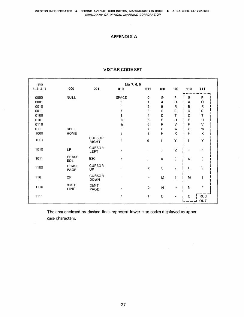
APPENDIX A
VISTAR CODE SET
Bits Bits 7,6,5 4,3,2,1 000 001 010 011 100 101 110 111
r----- --, 0000 NUll SPACE a @ P @ P 0001 A Q A Q
0010 2 B R B R 0011 # 3 C S C S 0100 $ 4 D T D T 0101 % 5 E U E U 0110 & 6 F V F V 0111 BEll 7 G W G W 1000 HOME 8 H X H X
1001 CURSOR RIGHT 9 y y
1010 IF CURSOR J Z J Z lEFT
1011 ERASE ESC + K K EOl
1100 ERASE CURSOR < l \ l \ PAGE UP
1101 CR CURSOR M M DOWN
1110 XMIT XMIT > N N LINE PAGE 1-
- _.--I
1111 ? 0 + o JRUB L __ --' OUT
The area enclosed by dashed lines represent lower case codes displayed as upper
case characters.
27
INFOTON INCORPORATED • SECOND AVENUE, BURLINGTON, MASSACHUSETTS 01803 • AREA CODE 617 272·6660 SUBSIDIARY OF OPTICAL SCANNING CORPORA TION
28
INFOTON INCORPORATED • SECOND AVENUE. BURLINGTON. MASSACHUSETTS 01803 • AREA CODE 617 272·6660 SUBSIDIARY OF OPTICAL SCANNING CORPORA TlON
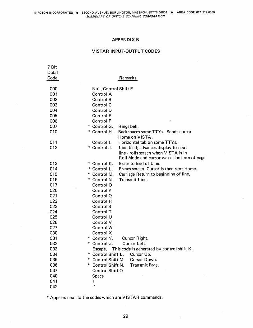
7 Bit Octal Code
000 001 002 003 004 005 006 007 010
011 012
013 014 015 016 017 020 021 022 023
·024 025 026 027 030 031 032 033 034 035 036 037 040 041 042
APPENDIX B
VISTAR INPUT-OUTPUT CODES
Remarks
Null, Control Shift P Control A Control B Control C Control D Control E Control F
* Control G. * Control H.
Control I. * Control J.
* Control K. * Control L. * Control M. * Control N.
Control 0 Control P Control Q Control R Control S Control T Control U Control V Control W Control X
Rings bell. Backspaces some TTYs. Sends cursor Home on VISTA. Horizontal tab on some TTYs. Line feed; advances display to next line - rolls screen when VISTA is in Roll Mode and cursor was at bottom of page. Erase to End of Line. Erases screen. Cursor is then sent Home. Carriage Return to beginning of line. Transmit Line.
* Control Y. Cursor Right. * Control Z. Cursor Left.
Escape. This code is generated by control shift K. * Control Shift L. Cursor Up. * Control Shift M. Cursor Down. * Control Shift N. Transmit Page.
Control Shift 0 Space !
* Appears next to the codes which are VISTAR commands.
29
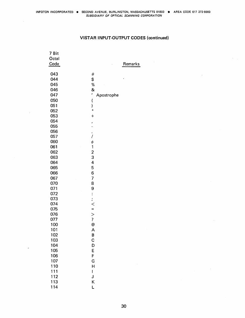
INFOTON INCORPORATED • SECOND AVENUE, BURLINGTON, MASSACHUSETTS 01803 • AREA CODE 617 272·6660 SUBSIDIARY OF OPTICAL SCANNING CORPORA TlON
VISTAR I NPUT-OUTPUT CODES (continued)
7 Bit Octal Code Remarks
043 # 044 $ 045 % 046 & 047 ' Apostrophe 050 051 052 * 053 + 054 055 056 057 / 060 ¢ 061 1 062 2 063 3 064 4 065 5 066 6 067 7 070 8 071 9 072 '073 074 < 075 076 > 077 ? 100 @
101 A 102 B 103 C 104 D 105 E 106 F 107 G 110 H 111 I 112 J 113 K 114 L
30
INFOTON INCORPORATED • SECOND AVENUE, BURLINGTON, MASSACHUSETTS 01803 • AREA CODE 617 272·6660 SUBSIDIARY OF OPTICAL SCANNING CORPORA TlON
VISTAR INPUT-OUTPUT CODES (continued)
7 Bit Octal Code Remarks
115 M 116 N 117 0 120 P 121 Q 122 R 123 S 124 T 125 U 126 V 127 W 130 X 131 y 132 Z 133 [ Shift K. 134 \ Shift L. 135 ] Shift M. 136 t 137 +-
140 @
141 A 142 B 143 C 144 D 145 E 146 F 147 G 150 H 151 I 152 SEE J 153 K 154 NOTE L 155 M 156 N 157 0 160 P 161 Q 162 R 163 S 164 T 165 U
31
INFOTON INCORPORATED • SECOND AVENUE, BURLINGTON, MASSACHUSETTS 01803 • AREA CODE 617 272·6660 SUBSIDIARY OF OPTICAL SCANNING CORPORA TlON
7 Bit Octal Code
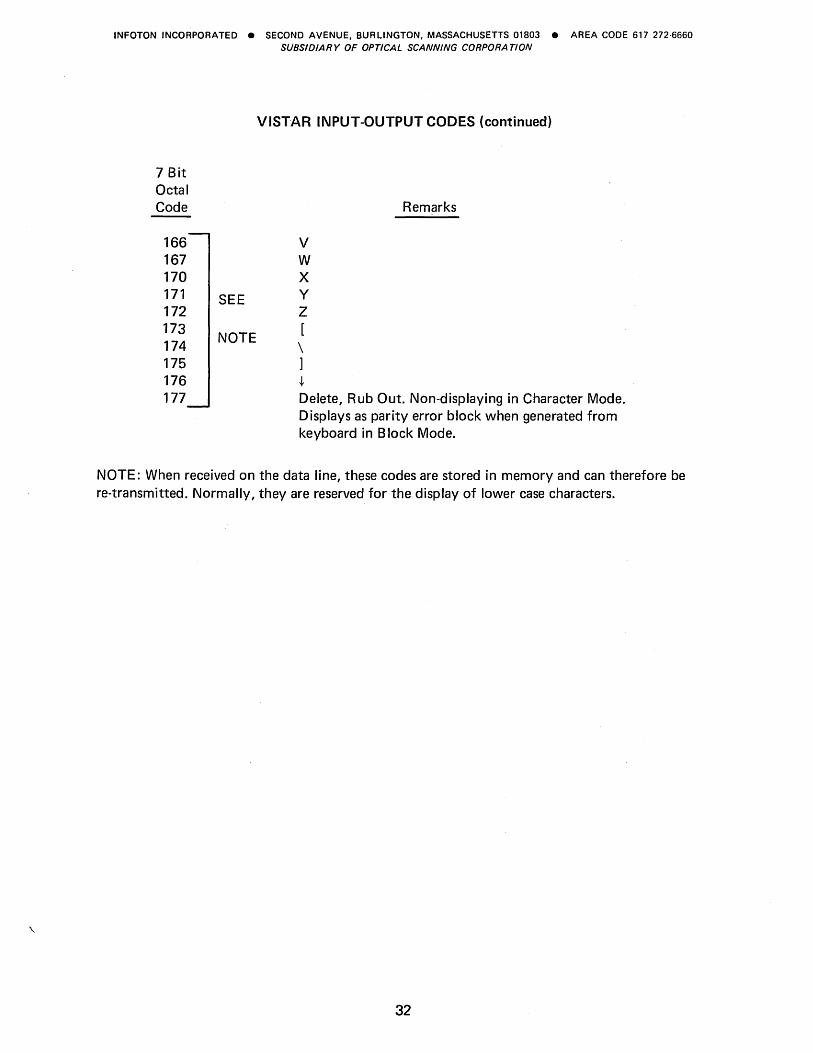
166 167 170 171 172 173 174 175 176 177
SEE
NOTE
VISTAR INPUT-OUTPUT CODES (continued)
v W X y Z [
\ ]
t
Remarks
Delete, Rub Out. Non-displaying in Character Mode. Displays as parity error block when generated from keyboard in B lock Mode.
NOTE: When received on the data line, these codes are stored in memory and can therefore be re-transmitted. Normally, they are reserved for the display of lower case characters.
32
INFOTON INCORPORATED • SECOND AVENUE, BURLINGTON, MASSACHUSETTS 01803 • AREA CODE 617 272·6660 SUBSIDIARY OF OPTICAL SCANNING CORPORA TION
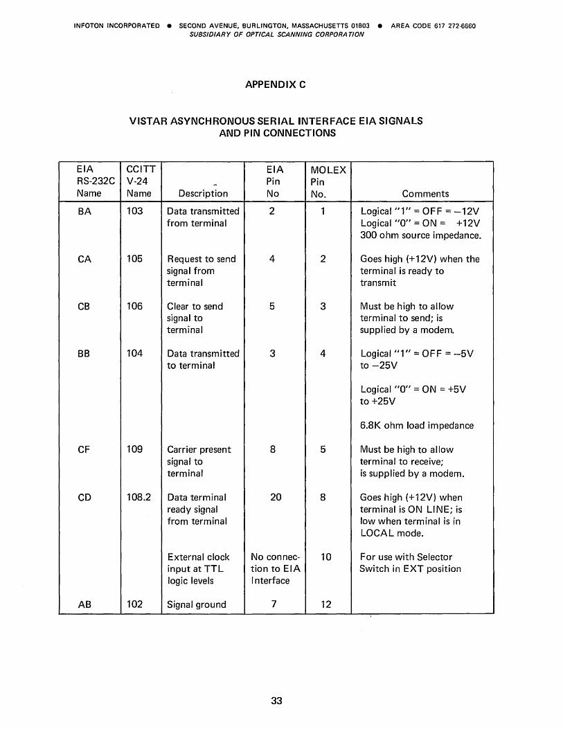
EIA RS-232C Name
BA
CA
CB
BB
CF
CD
AB
APPENDIX C
VISTAR ASYNCHRONOUS SERIAL INTERFACE EIA SIGNALS AND PIN CONNECTIONS
CCITT EIA MOLEX V-24 - Pin Pin Name Description No No. Comments
103 Data transmitted 2 1 Logical "1" = OFF = -12V from terminal Logical "0" = ON = +12V
300 ohm source impedance.
105 Request to send 4 2 Goes high (+12V) when the signal from terminal is ready to terminal transmit
106 C lear to send 5 3 Must be high to allow signal to terminal to send; is terminal supplied by a modem.
104 Data transmitted 3 4 Logical "1" = OF F = -5V to terminal to -25V
Logical "0" = ON = +5V to +25V
6.8K ohm load impedance
109 Carrier present 8 5 Must be high to allow signal to term ina I to receive; terminal is supplied by a modem.
108.2 Data terminal 20 8 Goes high (+12V) when ready signal terminal is ON LINE; is from terminal low when terminal is in
LOCAL mode.
External clock No connec- 10 For use with Selector input at TTL tion to EIA Switch in EXT position logic levels Interface
102 Signal ground 7 12
33

INFOTON INCORPORATED • SECOND AVENUE, BURLINGTON, MASSACHUSETTS 01803 • AREA CODE 617 272·6660 SUBSIDIARY OF OPTICAL SCANNING CORPORA TION

INFOTON INCORPORATED • SECOND AVENUE, BURLINGTON, MASSACHUSETTS 01803 • AREA CODE 617 272-6660 SUBSIDIARY OF OPTICAL SCANNING CORPORATION

INFOTON INCORPORATED • SECOND AVENUE, BURLINGTON, MASSACHUSETTS 01803 • AREA CODE 617 272·6660 SUBSIDIARY OF OPTICAL SCANNING CORPORA TlON


Infoton INFOTON INCORPORATED SECOND AVENUE, BURLINGTON, MASSACHUSETTS 01803 SUBSIDIARY OF OPTICAL SCANNING CORPORA TlON AREA CODe 617 272·6660
Document No. 02327 October/1972
2500