visual identification of weld defects using high dynamic...
TRANSCRIPT

Visual Identification of Weld Defects Using High Dynamic
Range Video Imaging
Technical Report
Submitted by
Whitney Jardine
August 4 2015
Submitted in partial fulfillment of the requirements for graduation from the
School of Welding Engineering Technology
Northern College of Applied Arts and Technology, Kirkland Lake Campus
i
Acknowledgements
This technical project could not have been possible without the help of numerous individuals.
First, I thank my research partners at the Materials Joining Innovation Center (MaJIC), for helping
make this technical research project possible. I am sincerely grateful to MaJIC employees for their continuous
support of my education and advancement in the welding industry. Evan Butler-Jones’ intuition and
enthusiasm inspired me as I began this project. Jeff Molyneaux provided continuous and support and
encouragement. Jack Pacey generously offered his skilled technical support from the beginning to the end of
the project. The co-op students who were employed at MaJIC, Justin Crick and Sean Morton also deserve
thanks for helping prepare plates and record video data.
I would like to thank Enceladus Imaging co-founders Alex Babut and Kalin Ovtcharov and Iliya
Sigal for providing their expertise and knowledge about the Enceladus software and imaging technology
which were the focus of my project.
The education, constant support and guidance required to complete my technical report was
provided by the knowledgeable teaching staff of Northern College. Dr. Graham Payne and Brenda Simpson
deserve a special thanks for being excellent technical project advisors, ensuring I met deadlines and helping
me produce the best quality work possible. I would like to also thank welding program coordinator and
professor, Josh Fuller for helping with several reviews as the report was completed.
I would lastly like to thank Fronius technicians, Schuyler Fowlow and Matthew Bolger, for helping
optimize the Fronius cold metal transfer (CMT)® parameters and for providing very thorough and
professional technical support.

ii
Table of Contents
Acknowledgements ........................................................................................................................................................................ i
Table of Contents.......................................................................................................................................................................... ii
Table of Figures, Images and Charts ........................................................................................................................................ iii
Abstract ........................................................................................................................................................................................... 1
Introduction and Problem Analysis ........................................................................................................................................... 2
Review of Previous Work ............................................................................................................................................................ 4
Experimental Methods ................................................................................................................................................................. 8
Experimental Results .................................................................................................................................................................. 12
Discussion .................................................................................................................................................................................... 22
Conclusions and Recommendations ........................................................................................................................................ 26
Appendices .......................................................................................................................................................................................
Appendix A: References ........................................................................................................................................................ 28
Appendix B: Figures............................................................................................................................................................... 30
Appendix C: List of Variables .............................................................................................................................................. 39
Appendix D: Video Images .................................................................................................................................................. 41

iii
Table of Figures, Images and Charts
Figures:
Figure 1 - Arc Images, order is GMAW, MCAW, FCAW (Levesque, 2007) ................................................................... 30
Figure 2 - Current & Voltage vs. Electrode Type vs. Penetration - Ar 15%CO2 Shielding Gas (Levesque, 2007) ... 30
Figure 3 -Pseudocolour Display of Metal Transfer Behavior (32V, 250A) (Ogawa, 2011) ............................................ 31
Figure 4 - Effect of External Laser Light on Arc Image, a) with laser illumination b) arc only (Ogawa, 2011) ........ 31
Figure 5 - Effect of Exposure Time on Image Quality (from long to short) (Ogawa, 2011) ........................................ 31
Figure 6 - Length of the column of liquid metal (CLM); a) pure Argon, b) 5% Oxygen (T. Nakamura, 2008) ......... 32
Figure 7 - New Torch to Shorten CLM by Supplying Adding Gas (T. Nakamura, 2008) ............................................. 32
Figure 8 - Change of CLM Length for Various Adding Gas Conditions (T. Nakamura, 2008) ................................... 33
Figure 9 - Developed Coaxial Hybrid Solid Wire (T. Nakamura, 2008) ............................................................................ 33
Figure 10 - Computer with Filer Box Next to Welding set up ............................................................................................ 34
Figure 11 - Point Grey Grasshopper3 4.1MB Colour USB3 Vision Camera (CMOSIS CMV4000-3E5) .................. 34
Figure 12 - Welding Jig with Fillet Joint, Camera, Laser Light and Torch set up ............................................................ 35
Figure 13 - Welding Jig with Fillet Joint, Camera, Laser Light (turned on) and Torch set up, ..................................... 35
Figure 14 - Welding Torch Holding Jig Attached to the Welding Carriage ...................................................................... 36
Figure 15 - Fronius TransPulseSynergic5000 CMT 650A Welding Machine ................................................................... 36
Figure 16 - Protective Camera Enclosure with ND ABS 2.0” O.D. UV Filter and Lockable Positioning Arm ........ 37
Figure 17 - Laser Light with Heat Sync on Lockable Positioning Arm ............................................................................. 37
Figure 18 - ND ABS 2.0" O.D. UV Filters – Unused vs used (with spatter/welding fumes) ....................................... 38
Figure 19 - 3mm and 5mm Gaps Created for Burn-Through Defect (right), and Normal Fillet Joint (left) .............. 38
Images:
Image 1: Spray – Two brightness ............................................................................................................................................. 42
Image 2: Spray Plate .................................................................................................................................................................... 41
Image 3: Spray - bright, plate .................................................................................................................................................... 42
Image 4: Spray - good, bright .................................................................................................................................................... 42
Image 5 - GMAW Spray Transfer Leading Fillet .................................................................................................................. 43
Image 6: Spray - with light ......................................................................................................................................................... 43
Image 7: Spray – Projected ........................................................................................................................................................ 44
Image 8: Spray - Leading2 ......................................................................................................................................................... 44
Image 9: Globular – Repelled ................................................................................................................................................... 45
Image 10: Globular – Leading .................................................................................................................................................. 45
Image 11: Globular – Trailing ................................................................................................................................................... 46
Image 12: Porosity - Bead, Lack of Gas .................................................................................................................................. 46

iv
Image 13: Porosity - Gas Interference ..................................................................................................................................... 47
Image 14: Porosity - Inadequate Gas ....................................................................................................................................... 47
Image 15: Porosity - Fillet, Lack of Gas .................................................................................................................................. 48
Image 16: Porosity - On Top of Porous Weld ....................................................................................................................... 48
Image 17: Porosity - Long CTWD ........................................................................................................................................... 49
Image 18: Unequal Legs – Trailing .......................................................................................................................................... 49
Image 19: Unequal Legs – Trailing, Bright ............................................................................................................................. 50
Image 20: Unequal Legs – Leading .......................................................................................................................................... 50
Image 21: Undercut - Trailing, Dark ........................................................................................................................................ 51
Image 22: Undercut – Trailing .................................................................................................................................................. 51
Image 23: Burn-Through – 3mm Gap .................................................................................................................................... 52
Image 24: Burn-Through - 5mm Gap, Leading ..................................................................................................................... 52
Image 25: Burn-Through - 5mm Gap, Trailing ..................................................................................................................... 53
Image 26: Lack of Fusion - Puddle Ahead ............................................................................................................................. 53
Image 27: Lack of Fusion - 5 degree push .............................................................................................................................. 54
Image 28: Lack of Fusion - 15 degree push ............................................................................................................................ 54
Image 29: Lack of Fusion - 25 degree push ............................................................................................................................ 55
Image 30: Irregular – Artifacts/No Focus .............................................................................................................................. 55
Image 31: Irregular - Leading, Joint Alignment ..................................................................................................................... 56
Image 32: Irregular - Trailing, Joint Alignment ...................................................................................................................... 56
Image 33: Irregular – Fluctuating Travel Speed ..................................................................................................................... 57
Image 35: Irregular - Uncleaned, Plate .................................................................................................................................... 57
Image 34: Irregular - High EV, no HDR ................................................................................................................................ 58
Image 36: CMT No HDR .......................................................................................................................................................... 59
Image 37: CMT - Fillet, HDR ................................................................................................................................................... 60
Image 38: CMT no HDR ........................................................................................................................................................... 61
Charts:
Table 1A Welding Parameters – GMAW: Spray Transfer ................................................................................................... 15
Table 1B Camera Parameters – GMAW: Spray Transfer .................................................................................................... 15
Table 2A Welding Parameters – GMAW: Globular Transfer ............................................................................................. 16
Table 2B Camera Parameters – GMAW: Globular Transfer .............................................................................................. 16
Table 3A: Welding Parameters – GMAW Spray Transfer: Porosity .................................................................................. 16
Table 3B Camera Parameters – GMAW Spray Transfer: Porosity .................................................................................... 17
Table 4A: Welding Parameters – GMAW Spray Transfer: Unequal Legs ........................................................................ 17
Table 4B: Welding Parameters – GMAW Spray Transfer: Unequal Legs ......................................................................... 17
Table 5A: Camera Parameters – GMAW Spray Transfer: Undercut ................................................................................. 18

v
Table 5B: Welding Parameters – GMAW Spray Transfer: Undercut ................................................................................ 18
Table 6A: Welding Parameters – GMAW: Burn Through .................................................................................................. 18
Table 6B: Camera Parameters – GMAW: Burn Through .................................................................................................... 19
Table 7A: Welding Parameters – GMAW Spray Transfer: Lack of Fusion ...................................................................... 19
Table 7B: Camera Parameters – GMAW Spray Transfer: Lack of Fusion ....................................................................... 19
Table 8A: Welding Parameters – GMAW Spray Transfer: Irregular ................................................................................. 20
Table 8B: Camera Parameters – GMAW Spray Transfer: Irregular ................................................................................... 20
Table 9A: Welding Parameters – GMAW CMT .................................................................................................................... 21
Table 9B: Camera Parameters – GMAW CMT ..................................................................................................................... 21

[1]
Abstract
Welders and weld inspectors are subjected to many occupational hazards, primarily ocular and
respiratory health problems because they need to be close to the welding operation to monitor its progress.
For this and other reasons, it is desirable to find methods to observe the welding arc using remotely operated
video systems. Common digital video imaging systems lack this capability due to the contrast between the
extremely bright arc and the darker surroundings. This technical project investigated the possibility of
addressing some of these concerns through the use of a High Dynamic Range Imaging (HDR-I) video
camera.
Video data of the gas metal arc welding process (GMAW), including both regular spray & cold metal
transfer (CMT)®, was collected and reviewed to determine if the camera could visualize weld details in real
time. Attempts were made to identify droplet size and pattern, weld pool/arc size, shape, and colour, weld
pool/arc relative position, and direction of the weld with respect to the seam. Additionally, video data was
reviewed to determine if defects (or sources of defects) could be repeatedly seen. Weld conditions were
optimized, defect production and identification methods were developed and a video library was created.
Results showed that the aforementioned weld details could be clearly identified. Interestingly, CMT®
wire retraction was clearly visible, and with specialized video equipment analysis software, the camera was
capable of visualizing points on the short-circuiting CMT® pulse. Defects such as porosity, torch and joint
misalignment, undercut, burn through and lack of fusion were also reliably observed.
This vision technology shows promise in reducing health and safety risks by allowing real-time
remote visualization of the welding process and identification of weld defect sources. The video quality may
potentially benefit welding personnel as they seek to gain a better understanding of the theoretical aspects of
welding processes.

[2]
Introduction and Problem Analysis
The luminance range found in a photograph taken at a single exposure is known as its dynamic
range. The human eye and brain are capable of viewing and interpreting visual information with a high
dynamic range of 103 – 104.18 brightness units (Cambridge in Colour, 2015), but the contrast between the
welding arc and its surroundings exceeds this capability. Thus a manual welder is restricted in his or her ability
to obtain detailed simultaneous views of the arc, the darker weld pool, and the even more poorly lit
surroundings as the weld progresses. Currently, welders must rely on green-shaded lenses to protect their eyes
while welding. These lenses are UV/IR Interference filter which eliminate 99.9997% of ultraviolet (UV)
radiation (UVA, B & C) and infrared radiation (IR), diminishing the high intensity light to a lower shade level
(EWeld, 2015).
Most welders are capable of using this limited visual information to make slight corrections as they
weld, but uncorrected defects occasionally occur, particularly if it is difficult for the welder to identify or
properly interpret the subtle visual information available as in the case of a welder trainee. High Dynamic
Range (HDR) images possess a very wide brightness range, usually up to 1015 luminance units, and thus
contain more discernable visual information than standard imaging formats, which usually do not exceed the
dynamic range of 103 units (Mantiuk & Krawczyk, 2007). HDR video imaging uses a computer algorithm to
combine a sequence of successive video frames taken at different camera exposure times into a single frame
containing combined visual detail from all individual frames. A commercially available HDR vision system,
offered by Enceladus Imaging and which was used to generate the data in this report, offers flicker-free,
highly detailed, full colour images in real-time and with high frame rate, up to 120 frames-per-second (fps).
These imaging characteristics provide more detailed visual information, which would be
advantageous to allowing rapid identification of (and adjustments to) critical welding parameters while the
weld is in progress and could lead to a variety of applications, including diminished rework rates, and more
consistent, higher quality welds.

[3]
In this technical project, a Point Grey® Grasshopper3 4.1MP Colour USB3 Vision HDR-I camera
was used with Enceladus Imaging’s Arc Eye software to provide video data. The primary goals of the project
were to determine how well the camera could capture important visual details, how well it could withstand
the heat and spatter associated with the welding environment, and to assess how user-friendly the camera and
software were.
Cold metal transfer (CMT)® is an adaptation of the GMAW process that involves very low heat
input, a short-circuiting pulse and a rapid push-pull wire feeder, allowing welding on very thin and advanced
materials to be achieved. The camera’s capability to visualize CMT® was evaluated on whether it produced
stable arc recognition at various points along the welding pulse.
[4]
Review of Previous Work
1 – (Levesque, 2007) TR – Mode of Metal Transfer Observation and Comparison with GMAW, FCAW, MCAW Electrodes
Levesque’s report compared droplet size and arc behavior, affecting current densities, weld profiles
and spatter levels. A Nikon Coolpix995 digital camera (15 fps) was coupled to a telescopic lens and placed
behind a UV welding filter plate. Bead on plate welds were produced using mild steel electrodes and base
metal. Control variables included using identical voltage and wire feed speed (amperage) settings for each wire
type, and using an 85% Argon – 15% Carbon Dioxide shielding gas.
The main research problem was to determine if MCAW and FCAW electrodes should be classified under the
same model as GMAW for modes of metal transfer as specified per the International Institute of Welding
(IIW). Levesque determined that metal-cored arc welding (MCAW) achieved streaming spray and then
projected spray transfer at lower power levels than GMAW. Classifying modes of metal transfer in the flux-
cored arc welding (FCAW) process was practically impossible since the mode of droplet transfer around the
central flux column was indistinguishable. Figure 1 (Appendix B) shows images taken with the camera.
Tubular FCAW wire required a high wire feed speed in order to achieve comparable amounts of penetration
to MCAW and GMAW (Appendix B: Figure 2). Suggestions included using a monochromatic backlight
above the weld arc and comparing the effect of various shielding gases.
2 - (Ogawa, 2011) High Speed Imaging Technique Part 1 – High Speed Imaging of Arc Welding Phenomena
This study focused on the complex interactions between the welding arc and its surroundings
occurring during the gas tungsten arc welding (GTAW) process where the goal was to find a way to achieve
‘in-situ’ voltage and amperage measurement through signal analysis. The study identified previously unknown
physical reactions that occurred under high temperature gradients and at high temperatures. The high speed
camera used a lower dynamic range than video cameras available at the time due to the high amount of
processing required, making the video less detailed. Challenges were encountered in storing, watching and

[5]
analyzing the very large amounts of data involved. Emission spectroscopy and monochromatic imaging were
used to determine the influence of metal vapour on appearance of the area surrounding the weld.
Thermal images of the GTAW metal transfer in a pseudo-colour display were used to emphasise
physical changes (Appendix B: Figure 3). The quality of the image directly related to the amount of noise, and
arc light generated substantial levels of noise. In order to improve image quality, the researchers used red
monochromatic light illumination since it consisted of a different wavelength than those of the arc spectrum.
The weld, slag and metal vapor appeared clearer with use of the laser due to more light being scattered,
causing the recorded image to capture more details of the rougher surfaces. Less scattering occurred when the
monochromatic light illuminated the molten pool, due to the liquid surface tension and high reflectivity of the
weld pool. (Appendix B: Figure 4). The effect of exposure time on image quality showed that the image
darkened as exposure time decreased (from x64 to x1), since a larger range of light can be captured with
longer exposure times (Appendix B: Figure 5).
3 - (T. Nakamura, 2008) Improvement of MIG Welding Stability in Pure Argon Shielding Gas Using Small Amounts of Oxygen and Coaxial Hybrid Solid Wire
Argon shielding gas usually includes small amounts (1-5%) of oxygen or carbon dioxide to improve
arc stability (Howard & Helzer, 2011). The objective of the research described in this article was to determine
the conditions which made the welding arc in pure argon unstable, and to find methods to improve its
stability. Adding oxygen in an argon gas mixture lowered joint ductility and toughness, deteriorating the
quality of the joint. For applications requiring high joint quality, ductility, and toughness, the GTAW process
is used with a pure argon shielding gas. Unfortunately, GTAW has a much lower rate of metal deposition
compared to GMAW (Kou, 2003).
The unstable welding conditions were determined to be caused by the presence of a column of liquid
metal (CLM) generated at the wire tip. Oxygen in the shielding gas minimized the length of the CLM
(Appendix B: Figure 6), improving weld quality. It was identified that pure argon led to a long CLM which

[6]
caused undercut and asymmetric penetration shapes. The CLM led to irregular arc movement and it was
found that shortening the CLM produced a stable welding arc and defect-free weld.
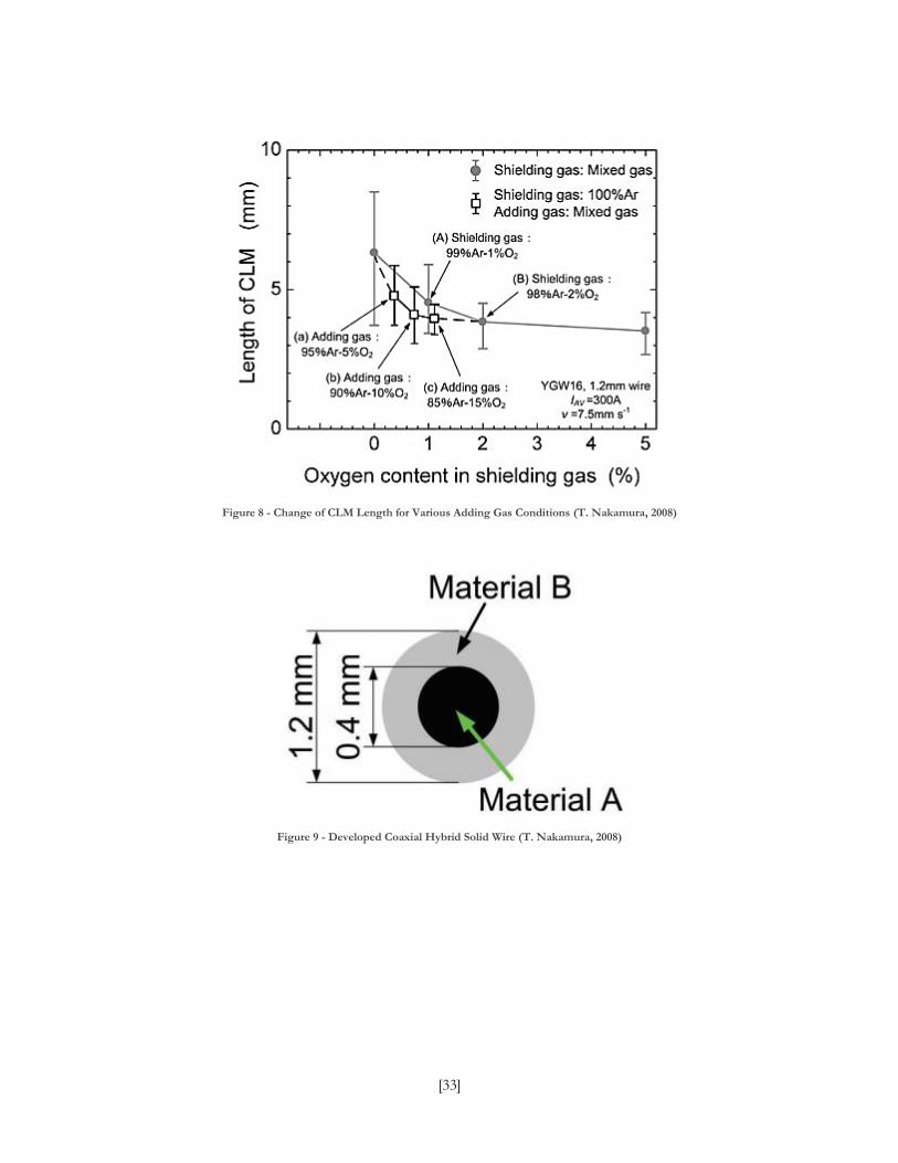
The project described two methods for improvement of GMAW arc stability while using pure argon
shielding. The first solution involved creating a new torch design with a small port adjacent to the wire to
supply a second gas. The goal was to obtain an oxygen rich atmosphere in the vicinity of the CLM. Figures 7
and 8 (Appendix B) show that this technique permitted shortening of the CLM while avoiding any
deterioration in weld integrity. The second method used to improve welding stability was to create a hybrid
solid wire consisting of two filler metals with differing melting temperatures.(Appendix B: Figure 9) The
concept was that the inside of the wire would melt more quickly, preventing a tapered shape (or ‘pencil
shape’) from forming at the wire tip, resulting in a shorter CLM. This method allowed pure argon to be used
without effects caused by oxygen contamination.
4 – (Talalaev, Veinthal, Laansoo, & Sarkans, 2012) Cold Metal Transfer (CMT®) Welding of Thin Sheet Metal Products
The CMT® pulse is a derivative of the common GMAW process and is based on controlled pulsed welding
currents and voltages, and high frequency wire retraction. Filler metal is transferred to the welding pool
during the short-circuit part of the pulse (without voltage or current) at a rate of about 70 droplets per second
(Talalaev, Veinthal, Laansoo, & Sarkans, 2012).
The study investigated the possibility of welding thin stainless steel and aluminum sheet metal using
an optimized robotic CMT® process. High levels of porosity, distortions and unacceptable shape of the weld
bead limited the use of CMT® for this application.
Higher levels of porosity were attributed to a relatively cooler arc and weld pool, which trapped the
absorbed gases before they could diffuse to the outer surface of the weld. This problem was corrected by
increasing shielding gas flow or by adding shielding gas behind the welding gun. The research determined thin
stainless steel and aluminum sheet metal products could be successfully robotically welded using the CMT®

[7]
process. With appropriate welding speeds, CMT® was found suitable for spatter-free welding of thin sheet
metal.
[8]
Experimental Methods
Equipment & Set-Up
A computer tower and screen were placed on a moveable cart and an air filter box was created
around the computer tower to protect it from excessive particulate (Appendix B: Figure 10). The computer
had a 1 terabyte drive used to store video data. A Point Grey® 4.1 MP Color Grasshopper3 camera with a
25mm Edmund Optics® compact fixed focal length lens (Appendix B: Figure 11) was mounted onto a
lockable positioning arm and pointed at the weld tip at various angles such that it was 10 to 20cm away
(Babut, Ovtcharov, & Sigal, 2015), then securely tightened to a Bug-O® travel carriage. A red LED (light-
emitting diode) light was positioned directly opposite to the camera in the same fashion and a USB 3.0 cable
was connected to the camera from the computer (Appendix B: Figures 12 & 13). These were positioned and
elevated on a separate welding table and the welding torch holding jig was attached to the travel carriage
(Appendix B: Figure 14).
Welding focused on fillet welds made in the flat position, but included several bead-on-plate videos
for comparison. A flat position welding jig was created by joining two plates at 90° to form a V-shape where
the plates would rest prior to welding the fillet joint. The jig was connected to a stand to elevate the fillet joint
to a convenient height. Fillet joints were completed using two 10mm x 50mm x 250mm plates tack welded at
the ends using SMAW 3.2mm E4918 electrodes. Plates were ground to remove mill scale to produce
consistent, clean welds and promote reflectivity of light in the joint during positioning and while welding
(Appendix D: Images 31 & 32).
Plain carbon mild steel was used as a base metal and GMAW spray transfer were used, since this
combination provided consistently clear video images. Welding variables to achieve spray transfer were 28
volts DCEP, 10.7m/min wire-feed-speed (215 amps), 18cm/min travel speed and 15mm contact tip-to-work
distance (CTWD). Air Liquide BlueShield 0.9mm ER49S-6 solid wire was selected since a smaller wire
diameter requires less heat input (compared to1.2mm), providing a reduced dynamic range (light intensity)

[9]
between the arc and the surroundings. Gas pressure was 8.5 L/min, using Air Liquide Argoshield 5 (95%Ar –
5%O2). A Fronius TransPulseSynergic5000 CMT 650A® welding machine (Appendix B: Figure 15) with a
water cooled AW5000 A/W MIG® welding torch was used for GMAW spray transfer and a water cooled
PullMig-CMT® push/pull welding torch was used for CMT®. Attempts were made to visualize MCAW and
FCAW, but this proved difficult and no further tests were pursued.
Method
To provide clear video images with optimal brightness and contrast, the first step was to focus the
camera. To focus the camera, shutter speed was increased (100ms), and frame rate was lowered (10 fps), while
illuminating the workpiece with the LED oriented in such a manner as to produce mirror-like reflection of
the light into the camera from the workpiece. After the camera was focused to the wire, frame rate was
increased (120fps), camera HDR mode was enabled, and exposure value/brightness range (2.12 to 2.42Δev)
and initial shutter speed (0.016ms) were selected. The aperture ring on the camera was set at 8 f-stops, and a
ND ABS 2.0” outer diameter UV filter (Babut, Ovtcharov, & Sigal, 2015) was placed in front of the camera
lens on the protective enclosure (Appendix B: Figure 16). Lastly, before welding, the red LED light was
turned on (Appendix B: Figure 17).
Baseline image development involved performing welds to determine the optimal welding parameters
to be used. Several torch and camera positions were used while ensuring the welding torch tip and the joint
were always included in the video. Leading and trailing views of the welds were taken, and each recording was
evaluated to determine if the droplet’s size and pattern within the arc could be visually distinguished, whether
the weld pool/arc size, shape and colour could easily be discerned, if the camera could see the relative
position of the weld pool/arc, and if the direction of the weld with respect to the seam was identifiable. The
internal temperature of the camera was monitored while welding to determine whether it could withstand the
heat (max internal temp 50°C). The clear protective UV filter was removable and was replaced when the
spatter began to accumulate, avoiding blurred images (Appendix B: Figure 18). Ease of use was qualitatively
assessed, with attention to camera positioning, focusing and software.

[10]
The defect simulation portion of this research project focused on creating repeatable tests evaluating
the ability of the camera to capture visual cues indicative of the presence of a weld defect, of a lack thereof,
produced while welding. Five common weld defects were simulated, including porosity, torch misalignment,
undercut, burn through, and lack of fusion. The first defect identification test was determining the visual
effects of porosity caused by lack of (or inadequate) shielding gas, or by having an excessively long CTWD
(over 19mm). Compressed air was blown in the vicinity of the arc to disrupt the shielding gas. Secondly,
defects were caused by misaligning the torch with the fillet joint to create unequal weld leg sizes. Next,
undercut defects were made by increasing travel-speed from 18cm/min to approx. 24cm/min until excessive
wetting occurred at the weld toes. Burn-through defects were generated using three inch long, 3mm and 5mm
deep gaps on the mating edge of the fillet joint causing the weld pool size to decrease (Appendix B: Figure
19). GMAW globular transfer was optimized to study this defect since its shorter, narrower arc size improved
weld pool flow into gaps. Lastly, lack of fusion defects were developed. Lack of fusion is known to occur
when the weld puddle travels ahead of the arc (Howard & Helzer, 2011). The welding torch was positioned at
5, 15, and 25 degree ‘push’ angles since most practical applications and/or misalignments occur within this
range. Recording was done on different days with a variety of camera angles to allow assessment of the
repeatability of the testing done.
For observation of welding using the CMT® process, an external trigger circuit was used to sync the
camera’s recording software with the pulse of the weld. A uniform sensor-level delay of 0 to 20 ms between
the trigger pulse and frame capture was applied where necessary to observe the appearance of the arc and
weld metal transfer from the electrode into the weld pool. The camera’s capability to visualize CMT®
depended on whether it obtained stable arc recognition with leading, trailing and side views at various trigger
delays.

[11]
As testing was completed, a library of videos with descriptions were made. The following questions
were considered:
1. Did the camera overheat due to its proximity to the high-temperature welding environment?
2. Did the spatter created while welding negatively affect the camera’s visibility, and to what
extent?
And in terms of usability,
3. How intuitive was the software?
4. How difficult was it to position the camera to provide a sufficient amount of distinguishable
features?
Consideration of the above questions determined the camera’s usability and efficiency and it’s suitability for
the welding industry was thoroughly assessed.

[12]
Experimental Results
Visualizing Details
The camera could visualize increasing arc sizes and shapes while altering welding voltage. Droplet
size and pattern were clearly identified within the arc, provided that the camera was properly focused on the
electrode prior to welding. Increasing the exposure value/initial shutter speed caused droplet visibility to
decrease, increasing the overall brightness. Increasing the wire-feed-speed (amperage) caused droplets to
decrease in size and increase velocity (Table 1). Details such as grinder marks, residual spatter and defects
were visible on the base metal’s surface before and while welding (Table 8)(Appendix D: Images 31, 32).
The molten metal flow, solidification pattern, colour, shape, and leg size were details that the camera
also consistently recorded in the weld pool. Use of 95% argon shielding gas with a balance of oxygen,
provided good arc stability and bead appearance. Trailing views in particular showed the concavity/convexity
of the weld. Use of the red LED light caused the weld, slag and metal vapour to appear clearer and the
relative position of the weld pool/arc and its direction with respect to the seam was visible.
Attempts were made to visualize MCAW and FCAW. Use of metal-cored wire resulted in flickering
illumination levels. FCAW was also difficult to visualize.
Defect Identification
Specific visual cues allowing rapid, real-time identification of weld defects that were evaluated. As per
Images 12-17 (Appendix D), videos of welding with lack of/interrupted shielding gas and excessively high
CTWD showed visual cues such as irregular, inconsistent arcs, high spatter and indistinguishable droplet
patterns (Table 3). Porosity was easily identified while welding. Trailing views worked best to visualize
porosity (voids) forming and impurities gathering along the solidifying weld metal edge. Impurities caused by
uncleaned base metal were visualized as small, shiny particles floating in the molten weld pool (Table
8)(Appendix D: Images 35 and 36).

[13]
Defects caused by having the torch misaligned to the fillet joint were produced with relative ease,
since proper torch alignment was difficult due to the nature of the welding jig set-up. Video data collected
with the torch misaligned showed unequally-sized legs (Table 4)(Appendix D: Images 18-20). Undercut
produced by increasing the welding travel speed showed clear indications of wetting and weld pool
displacement. Trailing views showed the base metal melting at the toes of the weld pool and insufficient filler
metal deposition resulting in undercut (Table 5)(Appendix D: Images 21, 22).
Spray transfer in GMAW was achieved using high voltages, meaning the arc became longer and
wider (Kou, 2003). When the burn-through defects were created, the wide arc in spray transfer caused the
weld pool to retain a consistent size while welding over gaps. Optimizing welding parameters for GMAW
globular transfer caused a shorter, narrower arc, which in turn caused the weld pool to visibly flow into the
gaps (Table 6)(Appendix D: Images 23-25). This was best observed with a leading view (Table 2). Video data
showed that positioning the welding torch as 5, 15, and 25 degree ‘push’ angles, the weld metal increasingly
pooled in front of the arc. Lack of fusion was evident since weld metal flow into the joint center was impeded
by the puddle ahead of the arc (Table 7)(Images 26-29).
CMT® Imaging
Results showed that visual details such as metal transfer, weld pool/arc size, shape and colour, weld
pool/arc relative position, and direction of the weld with respect to the seam could be clearly perceived while
using the CMT® GMAW process. The CMT® method was clearly visualized using a proprietary triggering
device used to sync the camera to a chosen phase of the CMT® waveform, allowing useful refinement of the
imaging point along the weld’s light intensity waveform. (Table 9). The surface tension created in the liquid
metal droplet as it is transferred from the electrode tip to the base metal/weld pool could be observed using
the camera. Weld pool solidification, size and orientation were also visible.
Camera Usability
The camera and software settings were well described in the user’s manual and they were simple to
alter. Changing the optimized dynamic exposure values higher or lower caused artifacts to appear around the

[14]
welding arc (Table 8)(Appendix D: Image 30). Enceladus Imaging was also made aware of several imaging
issues encountered, including times when the video would flip orientation (record upside-down), skip frames
or play frames in reverse (Table 8). A list of electrical and welding variables was made to improve software
usability by facilitating parameter identification for future revision (Appendix C)
Fixturing the camera was the most challenging part of the set-up. The positioning arms were difficult
to properly lock in place, which sometime caused the camera to slightly shift out of focus and away from the
arc. Changing the specific camera angle would also significantly alter the amount of features distinguishable
while welding. Focusing the camera properly required a bright light under the welding tip; otherwise, it was
impossible to see the weld tip. When proper set-up and optimal settings were used, the camera would record
a high-quality welding video. The camera did not reach an unsafe internal temperature (50°C) since its
protective casing and lens withstood the intense heat and spatter associated with the welding environment.
The protective UV filter had to be replaced several times during the course of the study (after approx. 10hrs
of welding) to ensure clear, high-quality videos were filmed. Some problems encountered while storing data
included a 20 to 30 second wait time to analyze and store video files, most likely caused by inadequate storage
drive and connection capabilities. Lastly, a video data library was made. Images of these videos along with
their descriptions can be found in Appendix D.

[15]
Table 1-A: Welding Parameters – GMAW Spray Transfer
Image
Number (Appendix E)
Video File Name
View Weld Type
Voltage (V)
Wire Feed Speed (ipm)
Current (A)
Contact Tip-to-Work
distance (in)
1 Spray – two brightness
Side Bead-
on plate
28 415 210 ½
2 Spray - plate Side Bead-
on plate
28 415 208 ½
3 Spray –
bright, plate Side
Bead-on
plate 28 415 210 ½
4 Spray – good,
plate Side
Bead-on
plate 28 415 206 ½
5 Spray – leading
Leading Fillet 27 415 201 ½
6 Spray – with
light Leading Fillet 27 415 204 ½
7 Spray –
projected Leading Fillet 30.5 420 212 ⅝
8 Spray – leading2
Leading Fillet 27 415 203 ½
Table 1-B: Camera Parameters: GMAW Spray Transfer
Image Number (Appendix E)
Video File Name
Exposure Value (Δev)
Frame Rate (ms)
1 Spray – two brightness
2.32 120
2 Spray –
bright, plate 2.32 120
3 Spray –
bright, plate 2.42 115
4 Spray – good,
plate 2.42 110
5 Spray – leading
2.12 120
6 Spray – with
light 2.22 120
7 Spray –
projected 2.22 120
8 Spray – leading2
2.22 100
Note: 0.016 ms initial shutter speed, High Dynamic Range On

[16]
Table 2-A: Welding Parameters – GMAW Globular Transfer
Image Number (Appendix E)
Video File Name
Voltage (V)
Wire Feed Speed (ipm)
Current (A)
Contact Tip-to-Work
distance (in)
9 Globular – Repelled
24.5 310 176 ½
10 Globular –
Leading
24.5 250 182 ½
11 Globular –
Trailing
24.5 250 182 ½
Note: Fillet welds, leading view
Table 2-B: Camera Parameters: GMAW Globular Transfer
Image Number (Appendix E)
Video File Name Exposure Value
(Δev)
9 Globular – Repelled 2.12
10 Globular – Leading 2.32
11 Globular – Trailing 2.32
Note: 0.016 ms initial shutter speed, 120 ms frame rate, High Dynamic Range On
Table 3-A: Welding Parameters – GMAW Spray Transfer: Porosity
Image Number (Appendix E)
Video File Name
View Weld Type
Voltage (V)
Wire Feed Speed (ipm)
Current (A)
Contact Tip-to-Work
distance (in)
12 Porosity –
bead, lack of gas
Side Bead on
plate 28 415 205 ½
13 Porosity – gas interference
Leading Fillet 27 415 203 ⅝
14 Porosity – inadequate
gas Trailing Fillet 27 415 200 ⅝
15 Porosity –
fillet, lack of gas
Trailing Fillet 27 415 198 ⅝
16 Porosity – on top of porous
weld Trailing Fillet 27 415 195 ½
17 Porosity –
long CTWD Trailing Fillet 28 420 210 ⅞

[17]
Table 3-B: Camera Parameters: GMAW Spray Transfer: Porosity
Image Number (Appendix E)
Video File Name Exposure Value (Δev)
12 Porosity – plate, no gas 2.42
13 Porosity – gas interference 2.22
14 Porosity – inadequate gas 2.02
15 Porosity – lack of gas 2.02
16 Porosity – on top of porous
weld 2.12
17 Porosity – long CTWD 2.12
Note: 0.016 ms initial shutter speed, 120 ms frame rate, High Dynamic Range On
Table 4-A: Welding Parameters – GMAW Spray Transfer: Unequal Legs
Image Number (Appendix E)
Video File Name
Voltage (V)
Wire Feed Speed (ipm)
Current (A) Contact Tip-
to-Work distance (in)
18 Unequal legs
– Trailing
27 415 200 ½
19 Unequal legs
– Bright
27 415 202 ½
20 Unequal legs
– Leading
27 415 198 ½
Note: Fillet welds, trailing view
Note: 0.016 ms initial shutter speed, 120 ms frame rate, High Dynamic Range On
Table 4-B: Camera Parameters: GMAW Spray Transfer: Unequal Legs
Image Number (Appendix E)
Video File Name Exposure Value (Δev)
18 Unequal legs – Trailing 2.42
19 Unequal legs – Bright 2.02
20 Unequal legs – Leading 2.22

[18]
Table 5-A: Welding Parameters – GMAW Spray Transfer: Undercut
Image Number (Appendix E)
Video File Name
Voltage (V) Wire Feed
Speed (ipm) Current (A)
Contact Tip-to-Work
distance (in)
21 Undercut – trailing, dark
28 420 208 ½
22 Undercut –
trailing 28 420 205 ⅝
Note: Fillet welds, trailing view.
Table 5-B: Camera Parameters: GMAW Spray Transfer: Undercut
Image Number (Appendix E)
Video File Name Exposure Value (Δev)
21 Undercut – Trailing, dark 2.12
22 Undercut – Trailing 2.42
Note: 0.016 ms initial shutter speed, 120 ms frame rate, High Dynamic Range On
Table 6-A: Welding Parameters – GMAW: Burn Through
Image Number (Appendix E)
Video File Name
Process/Mode of Metal
Transfer
View Voltage (V) Wire Feed
Speed (ipm)
Current (A)
Contact Tip-to-Work
distance (in)
23 Burn-
through – 3mm gap
Spray Leading 27 415 200 ⅝
24
Burn-through – 5mm gap leading
Globular Leading 24.5 350 187 ½
25
Burn-through – 5mm gap trailing
Globular Trailing 24.5 350 190 ½
Note: Fillet welds

[19]
Table 6-B: Camera Parameters: GMAW: Burn-Through
Image Number (Appendix E)
Video File Name Exposure Value (Δev)
23 Burn-through – 3mm gap 2.22
24 Burn-through – 5mm gap,
leading 2.32
25 Burn-through – 5mm gap,
trailing 2.32
Note: 0.016ms initial shutter speed, 120ms frame rate, High Dynamic Range On
Table 7-A: Welding Parameters – GMAW Spray Transfer: Lack of Fusion
Image Number (Appendix E)
Video File Name
View Weld Type Voltage
(V)
Wire Feed Speed (ipm)
Current (A)
Contact Tip-to-Work
distance (in)
26
Lack of fusion – puddle ahead
Side Bead on
plate 28 420 210 ½
27
Lack of fusion – 5
degree push
Leading Fillet 28 420 207 ⅝
28
Lack of fusion –
15 degree push
Leading Fillet 28 420 208 ⅝
29
Lack of fusion –
25 degree push
Leading Fillet 28 420 207 ⅝
Table 7-B: Camera Parameters: GMAW Spray Transfer: Lack of Fusion
Image Number (Appendix E)
Video File Name Exposure Value (Δev)
26 Lack of fusion – puddle ahead 2.12
27 Lack of fusion – 5 degree push 2.42
28 Lack of fusion – 15 degree
push 2.42
29 Lack of fusion – 25 degree
push 2.42
Note: 0.016ms initial shutter speed, 120ms frame rate, High Dynamic Range On

[20]
Table 8-A: Welding Parameters – GMAW: Irregular Videos
Image Number (Appendix E)
Video File Name
Process/Mode of Metal Transfer
View Weld Type
Voltage (V)
Wire Feed Speed (ipm)
Current (A)
Contact Tip-to-Work
distance (in)
30 Irregular – artifacts/no
focus Spray Side
Bead on
plate 28 420 212 ½
No Image
Irregular – reversed motion
Spray Leading Fillet 27 415 203 ½
31 Irregular –
leading, joint alignment
x Leading Fillet X x x x
32 Irregular –
trailing, joint alignment
x Leading Fillet X x x x
33 Irregular – fluctuating travel speed
Spray Leading Fillet 28 415 208 ½
34 Uncleaned –
plate Spray Side
Bead-on
plate 28 415 210 ½
35 Irregular –
High EV, no HDR
Spray Side Bead on
plate 27 415 200 ½
Table 8-B: Camera Parameters: GMAW Defects: Irregular Videos
Image Number (Appendix E)
Video File Name Exposure
Value (Δev)
Frame Rate (ms)
High Dynamic Range (on/off)
30 Irregular – artifacts/no focus 2.82 120 On
No Image
Irregular – reversed motion 2.22 120 On
31 Irregular – leading, joint
alignment 2.32 10 Off
32 Irregular – trailing, joint
alignment 2.32 10 Off
33 Irregular – fluctuating travel
speed 2.32 120 On
34 Uncleaned – plate 2.02 115 On
35 Irregular – High EV, no HDR
0.016 3.42 50 Off
Note: 0.016ms initial shutter speed

[21]
Table 9-A: Welding Parameters – GMAW CMT® Transfer
Image Number (Appendix E)
Video File Name View Weld Type
37 CMT – no HDR Side Bead on Plate
38 CMT – fillet, HDR Leading Fillet
39 CMT – trailing, no HDR Trailing Fillet
Note: Common parameters include: 10V, 130ipm, 88A and ½” contact tip-to-work distance
Table 9-B: Camera Parameters: GMAW CMT Transfer
Image Number (Appendix E)
Video File Name Exposure
Value (Δev)
High Dynamic Range (on/off)
37 CMT – no HDR 2.82 Off
38 CMT – fillet, HRD 2.82 On
39 CMT – trailing, no HDR 2.82 Off
Note: 0.016ms initial shutter speed, 120 ms frame rate

[22]
Discussion
Visualizing Details
Reviewing the Point Grey® Grasshopper3 camera and Arc Eye software showed that the steady
optimized video quality allowed repeatable identification of relevant weld details and defects. The HDR-I
welding camera provided high-quality videos that can be used to gain a better understanding of welding
processes (compared to using a textbook) that might improve the overall learning process of students,
educators, and trainees in the welding industry with its reliable droplet and weld detail identification (Tables 1
& 2)(Appendix D: Images 1-11). The camera and software were easy to understand and use. This may
potentially be useful in a setting where welder training times must be minimized.
The mode of metal transfer in MCAW was potentially perceived while using the camera technology.
Work by Levesque showed that it was comparable to GMAW since it achieved streaming spray and projected
spray transfer at lower power levels than GMAW (Levesque, 2007). The melting central flux column
associated with FCAW made identification of the mode of metal transfer impossible presumably due to the
inner core and the exterior wire melting at different rates (Howard B. Cary, 2011). Visualizing these process
using the HDR-I camera could help a welding student understand the reasoning behind specific electrode
designations and the electrodes affecting current densities.
Consistent with research by Ogawa, the weld, slag and metal vapour appeared clearer with use of a
monochromatic light due to more light being scattered, which caused the recorded image to capture more
details on rougher surfaces (Ogawa, 2011). This added feature would extend the camera’s capabilities to allow
visualization of additional weld details. Welders in training currently must perform a weld, allow it to cool,
review it, and identify any defects. Then, while re-welding, the trainee must attempt to remember what they
believed to have caused the defect, and attempt to make a correction. Use of the camera could allow real time
identification and correction of problems occurring in the trainees’ initial attempts to weld, thus promoting
faster-paced learning in a working environment.

[23]
As noted in results, the use of 95% argon shielding gas with a balance of oxygen, provided good arc
stability and bead appearance. The ability to observe the wire tip shape provided an understanding of the
parameters that affected its shape. This is consistent with the study done by Nakamura, where arc stability
and weld quality was improved when oxygen content in the argon was between 1-5%, since it minimized the
length of the column of liquid metal (CLM) on the wire tip (T. Nakamura, 2008). Oxygen has a lower
ionization potential and consequently promotes axial spray transfer at lower current densities compared to
CO2 (Kou, 2003).
Defect Identification
Reliable defect identification will aid inspection of welds and in turn can serve to improve productivity
and reliability of welded joints. Porosity defects are prevalent in industry where gas interruptions may be caused by
defected shielding gas delivery systems, inadequate gas pressure settings, leaking air lines and improper torch
contact tip-to-work distances. This defect can be avoided by ensuring the weld has proper shielding. The camera
was capable of visualizing porosity forming and impurities gathering along the solidifying weld metal edge
(Appendix D: Images 12-17).
Unequal weld leg size mainly results from poor torch alignment or incorrect robotic tool center point
calibration, inadequate fixturing of parts and poor joint fit up. It can be prevented by establishing a repeatable
welding set-up and by monitoring the position of the welding torch. Video data displayed torch misalignment
causing weld pool displacement and unequally-sized weld legs (Appendix D: Images 18-20). When joint and
fixturing complexity increases, proper alignment becomes increasingly difficult, thus leading to potential defects
such as unequal weld leg size and weld metal burn-through.
Burn-through defects primarily appear with incorrect joint fit-up, which is commonly caused by variations
in edge preparation (while grinding or cutting) or improper fixturing. Improper welding parameters for the selected
material thickness may also cause burn-through. Welding parameters such as part fit up, joint quality, and arc
alignment could easily be visualized with the camera while welding, allowing necessary optimization and alignment
corrections to made on-the-fly (Appendix D: Images 23-25, 31-32).

[24]
Undercut defects caused by excessively high travel speeds commonly occur, therefore viewing the
excessive wetting and weld pool displacement with a tool such as the HDR camera could allow immediate
adjustments of travel speeds, potentially lowering re-work rates. Trailing views worked best to visualize undercut
defects. Undercut defects are caused by a variety of factors including the use of improper welding parameters, such
as improper torch angles, and excessively high travel speeds, voltages or contact tip-to-work distances. Improper
torch angles could potentially be caused by improper joint fit-up and fixturing, damaged components, and
incorrect robotic tool center point calibration (Appendix D: Images 21-22).
Welding torch ‘push’ angle alignments may cause the weld puddle to flow ahead of the arc, and as a result,
lack of fusion can occur since the arc does not fully penetrate into the joint center, resulting in less penetration in
the base metal as heat is dissipated by the liquid weld puddle (Appendix D: Images 26-29). Improper welding
parameters and inappropriate work and travel angles are a main factor as to why this can occur. Lack of fusion may
also occur when the robotic tool center point is not properly calibrated. The HDR camera visualized the puddle
ahead of the arc, impeding the weld metal flow into the joint and could potentially be used to assist with the
identification and repair of this defect.
CMT Imaging
The ability to visualize details such as metal transfer, weld pool/arc size, shape and colour, weld
pool/arc relative position, and direction of the weld with respect to the seam may allow researchers to gain a
better overall understanding of the CMT® method. As per Images 36-38 (Appendix D), visualizing CMT®
gives welders the opportunity to witness weld details in real-time and this may permit a better understanding
of this specific welding process. Real-time videos of this mode of metal transfer may provide a way to further
optimize this advanced metal transfer method.
Camera Usability and Applications
Challenges storing, watching and analyzing data were encountered because of the large video file
sizes (approx. 1-2GB each). This is typical when attempting to visualize welding processes since the software

[25]
must process a large amount of data to produce high quality videos (Ogawa, 2011). Challenges may be
encountered in applications where down-time while waiting for video storage is unacceptable.
Hypothetically, the camera could replace auto-darkening lenses in welding helmets with a real-time
display of the weld. The steady optimized weld video quality could help eliminate eye-strain and headaches
caused by the rapidly varying image brightness produced by standard video cameras.
The compact size (5cm x 5cm x 15cm) of the camera shows promise to help welders perform high
quality welds in confined, dangerous, and typically inaccessible locations, and potentially may permit
increasing robotic welding applications of the HDR-I camera. In some situations, the high quality video
produced while welding may allow welders to be removed from proximity of the weld arc by using the HDR-
I camera to remotely visualize welds while they occur, potentially alleviating respiratory and ocular health and
safety risks caused by the welding fumes and arc.

[26]
Conclusions and Recommendations
Conclusions
This technical research project proved that the visual identification of high-quality weld details and
defects were possible using the Arc Eye software with the Point Grey® Grasshopper3 camera. HDR-I
imaging made studying the effects of welding parameters on arc shape/size, weld pool shape/size possible.
Physical occurrences that are typically unperceivable by the human eye, such as the droplet sizes and rates,
ripples caused by the droplets, weld metal flow and solidification patterns were consistently discernable with
the camera and its software. These unique details may hasten the learning process of welding industry
personnel, increase understanding of the welding processes studied, and in turn promote and improve the
growing welding industry.
Creating a safe and healthy working environment is crucial and the HDR-I welding camera studied in
this technical project is a tool that may someday allow elimination of some workplace hazards while
improving company’s overall productivity. The application of this technology potentially may permit workers
in welding environments to distance themselves from the arc and hazardous work environments.
Observing the relatively new GMAW cold metal transfer method via HDR-I allowed insight into the
process that would have been otherwise unattainable. Research determined the camera identified CMT® wire
retraction, weld details and offered stable arc recognition at points on the short-circuiting CMT® pulse. The
opportunity to witness such welding details in real-time may permit a better understanding of this specific
welding process.
Superior video quality offered by using the relatively low priced camera (compared to customized
digital high-speed-imaging cameras) may aid visual inspection while welding to reduce rework rates and
increasing productivity. The camera and software offered superior usability in terms of its ease of set-up and
use.

[27]
Knowledge gained in this investigation may be used to implement the camera in a variety of robotic
applications. Another anticipated application for the HDR video camera includes welding automation, where
remote, detailed observation of the welding process and/or weld defect prevention through machine vision
could be possible. Lastly, it is expected that recorded HDR videos could be used for research and
development purposes.
Recommendations
Prospective research projects with HDR-I vision technology include studying the effects of using various:
1. Wire sizes, compositions and types,
2. Base metals thicknesses and compositions,
3. Welding and travel positions,
4. Gas types.
Additional processes and modes of metal transfer of the GMAW process could also be investigated,
including:
5. Mechanized and manual GTAW,
6. Manual GMAW,
7. Lincoln Electric Surface Tension Transfer (STT)®
8. Other GMAW pulse controlling methods,
9. Modes of metal transfer of MCAW and FCAW electrodes (Levesque, 2007).
Other recommendations to improve overall usability are:
10. Controlling recordings with a remote rather than at the computer to ensure no time is
wasted in the recordings,
11. Adding a digital automatic focusing feature instead of a manual dial on the camera,
12. Improving the set-up by using more stable torch and camera holding assemblies,
13. Making the software controls more intuitive.

[28]
Appendices
Appendix A: References
1. Babut, A., Ovtcharov, K., & Sigal, I. (2015). Arc Eye User Guide. Enceladus Imaging Inc. Enceladus Imaging.
2. Callister, Jr., W. D., & Rethwisch, D. G. (2010). Materials Science and Engineering an Introduction (8th ed.).
John Wiley & Sons, Inc.
3. Cambridge in Colour. (2015). Cameras vs. The Human Eye. Retrieved from Cambridge in Colour:
http://www.cambridgeincolour.com/tutorials/cameras-vs-human-eye.htm
4. EWeld. (2015). How Does Auto Darkening Work. Retrieved from EWeld-au:
http://www.eweld.com.au/blogs/news/7074284-how-does-auto-darkening-work
5. Howard B. Cary, S. C. (2011). Modern Welding Technology (6th ed.). Pearson Education, Limited.
6. Howard, C. B., & Helzer, S. C. (2011). Modern Welding Technology (6th ed.). Pearson Education,
Limited.
7. Hughes, G. (2014). Project Funding Application Form. Northern College of Applied Arts & Technology.
Ontario Centers of Excellence.
8. Kou, S. (2003). Welding Metallurgy (2nd ed.). John Wiley & Sons, Inc.
9. Levesque, A. (2007). Technical Project - Mode of Metal Transfer Observation and Comparison with GMAW,
FCAW, MCAW electrodes. Northern College of Applied Arts and Technology.
10. Lincoln Electric. (2014, August). Gas Metal Arc Welding Guidelines. (Lincoln Electric) Retrieved from
http://www.lincolnelectric.com/assets/global/Products/Consumable_MIGGMAWWires-
SuperArc-SuperArcL-56/c4200.pdf
11. Mantiuk, R., & Krawczyk, G. (2007). High Dynamic Range Image and Video Compression - Fidelity Matching
and Human Visual Performance. (MPI Informatik) Retrieved from https://people.mpi-
inf.mpg.de/~mantiuk/papers/mantiuk07hdr_compression.pdf
12. Modes of Metal Transfer in GMAW. (1994). In Welding Metallurgy Carbon and Alloy Steels (4 ed., Vol.
1). American Welding Society.
13. Ogawa, Y. (2011). High Speed Imaging Technique Part 1 - High Speed Imaging of Arc Welding
Phenomena. Science & Tehcnology of Welding & Joining, 16(1), 33-43.
doi:10.1179/136217110X12785889549903
14. Point Grey Research Inc. (2015). Grasshopper3 4.1 MP Color USB3 Vision. (Point Grey Research Inc)
Retrieved from Point Grey Innovation in Imaging: http://ptgrey.com/grasshopper3-41-mp-
color-usb3-vision-cmosis-cmv4000-2-camera

[29]
15. T. Nakamura, K. H. (2008). Improvement of MIG Welding Stability in Pure Ar Shielding Gas Using
Small Amounts of Oxygen and Coaxial Hybrid Solid Wire. Science & Technology of Welding &
Joining, 13(1), 25-32. doi:10.1179/174329307X249289
16. Talalaev, R., Veinthal, R., Laansoo, A., & Sarkans, M. (2012). Cold Metal Transfer (CMT) Welding of
Thin Sheet Metal Products. Estonian Journal of Engineering, 18(3), 243-250.
doi:10.3176/eng.2012.3.09

[30]
Appendix B: Figures
Figure 1 - Arc Images, order is GMAW, MCAW, FCAW (Levesque, 2007)
Figure 2 - Current & Voltage vs. Electrode Type vs. Penetration - Ar 15%CO2 Shielding Gas (Levesque, 2007)

[31]
Figure 3 -Pseudocolour Display of Metal Transfer Behavior (32V, 250A) (Ogawa, 2011)
Figure 4 - Effect of External Monochromatic Light on Arc Image, a) with monochromatic illumination b) arc only (Ogawa, 2011)
Figure 5 - Effect of Exposure Time on Image Quality (from long to short) (Ogawa, 2011)

[32]
Figure 6 - Length of the column of liquid metal (CLM); a) pure Argon, b) 5% Oxygen (T. Nakamura, 2008)
Figure 7 - New Torch to Shorten CLM by Supplying Adding Gas (T. Nakamura, 2008)
[33]
Figure 8 - Change of CLM Length for Various Adding Gas Conditions (T. Nakamura, 2008)
Figure 9 - Developed Coaxial Hybrid Solid Wire (T. Nakamura, 2008)

[34]
Figure 10 - Computer with Filer Box Next to Welding set up
Figure 11 - Point Grey Grasshopper3 4.1MB Colour USB3 Vision Camera (CMOSIS CMV4000-3E5)

[35]
Figure 12 - Welding Jig with Fillet Joint, Camera, Red LED Light and Torch set up
Figure 13 - Welding Jig with Fillet Joint, Camera, Red LED Light (turned on) and Torch set up,
GMAW welding torch on positioning arm
Red LED light on positioning arm
Protective enclosure containing
PointGrey Camera Fillet Joint clamped on V-shaped jig

[36]
Figure 14 - Welding Torch Holding Jig Attached to the Welding Carriage
Figure 15 - Fronius TransPulseSynergic5000 CMT 650A Welding Machine
GMAW welding torch
Welded fillet joint
clamped on V-shaped jig
Torch holder height and angle positioners

[37]
Figure 16 - Protective Camera Enclosure with ND ABS 2.0” O.D. UV Filter and Lockable Positioning Arm
Figure 17 – Red LED Lights with Heat Sync on Lockable Positioning Arm
Heat-sync
LED lights, behind protective UV lens
Lockable Positioning Arm
Lockable Positioning Arm
Camera inside protective enclosure
UV Filter Lens

[38]
Figure 18 - ND ABS 2.0" O.D. UV Filters – Unused vs used (with spatter/welding fumes)
Figure 19 - 3mm and 5mm Gaps Created for Burn-Through Defect (right), Compared to Normal Fillet Joint (left)
3mm x 76mm gap 5mm x 76mm gap
[39]
Appendix C: List of Variables This list contains all relevant welding information and will facilitate proper report making.
Electrical Characteristics:
1. Voltage (V) 2. Current (A) 3. Wire feed speed (in/min or m/min) 4. Polarity (AC, DCEN, DCEP) 5. Contact tip to work distance (in or mm) 6. Electrode Extension (in or mm)
Welding Variables:
1. Process (FCAW, GMAW, GTAW, MCAW, PAW) 2. Process Mode (Manual, Semi-Auto, Machine, Auto) 3. Mode of metal transfer (globular, spray, pulsed-spray, cmt, short-circuit) 4. Gas: 1- Type; 2- Flow Rate (cfh); 3-Nozzle Dia (in or mm) 5. Electrode: 1- Composition; 2- Diameter (in or mm) 6. Base metal: 1- Material specification; 2- Thickness (in or mm) 7. Backing: 1-Material specification; 2-Thickness (in or mm) 8. Position (1G, 2G, 3G, 4G, 5G, 6G, 6GR; 1F, 2F, 3F, 4F)1 9. Joint Type (butt, corner, edge, lap, tee) 10. Joint Preparation (has many options for edge conditions) 11. Penetration (complete, partial) 12. Number of passes/Pass Number 13. Weld Size/Effective Throat Thickness (ETT): (in or mm) 14. Work angle (degrees) 15. Travel angle (degrees) 16. Travel Speed (in/min or mm/min) 17. Reference WPS and/or WPDS Numbers 18. Special Requirements (optional)
1 Positions could potentially be divided into three groups: Groove weld positions: 1G, 2G, 3G, 4G; Fillet weld positions: 1F, 2F, 3F, 4F; Pipe weld positions: 1G, 2G, 5G, 6G, 6GR. (see Figure A).
The Arc Eye software will have the option to input these parameters, adding them to the saved metadata files.

[40]
Figure A: Groove, fillet and pipe welding positions

[41]
Appendix D: Video Images
Image 1: Spray – two brightness
At nine seconds brightness wass increased. Gas flow around and over weld bead was visible. Low virtual exposure
increased droplet visibilty and high virtual exposure increased solidifying weld bead visibility. (virtual exposure
settings no longer included in software)
Image 20: Spray Plate
Weld used to set parameters.

[42]
Image 3: Spray - bright, plate
Puddle was slightly ahead of arc. Weld pool solidification was visible and the droplets appeared slightly out of
focus since image wass a bit too bright. Base metal condition was clearly visible. The droplets were small in size;
edge of weld pool, fillet and arc size were visible.
Image 4: Spray - good, bright
Both weld pool and droplets were clearly seen. There were some artifacts along the edge of the inner arc. Base
metal condition was clearly visible. The droplets were small in size; edge of weld pool, fillet and arc size were
visible.

[43]
Image 521 - GMAW Spray Transfer Leading Fillet
Joint and base metal condition were clearly visible. The droplets were smaller than the electrode diameter and fell
in a straight line at a mostly consistent rate. Edge of weld pool, fillet and arc size were clearly visible. Ripples
caused by droplet transfer were seen (in almost all fillet weld videos)
Image 622: Spray - with light
Joint and base metal condition were visible. The droplets were smaller than the electrode diameter and fell in a
straight and mostly consistent rate. Edge of weld pool, fillet and arc size were visible. The video shifted near the
end, at ten seconds.

[44]
Image 723: Spray – Projected
Joint and base metal condition were visible. The droplets were small in size and were falling at higher velocity (due
to higher V and I) and in a straight line at a consistent rate. Edge of weld pool, fillet and arc size were visible.
Image 824: Spray - Leading2
Joint and base metal condition were visible. The droplets were small in size and were falling at a mostly consistent
rate. Edge of weld pool, fillet and arc size were visible.

[45]
Image 925: Globular – Repelled
The droplets were seen to build up at the wire tip and eventually be repelled along the outside of the arc into the
weld pool, sometimes as spatter. The droplets were large in size and fell in an erratic pattern (causing the arc to
appear constant, with an irregular size). Edge of weld pool, fillet and arc size were visible.
Image 1026: Globular – Leading
Joint and base metal condition was visible. The droplets were larger than the electrode diameter and fell at a
consistent rate; edge of weld pool, fillet and arc size were visible. Arc is visibly narrower and shorter in globular
rather than spray transfer.
Repelled droplet
Spatter

[46]
Image 11: Globular – Trailing
Joint and base metal condition were visible. The droplets were larger than the electrode diameter and fell at a
consistent rate; edge of weld pool, fillet and arc size were visible.
Image 12: Porosity - Bead, Lack of Gas
Irregular arc pattern was due to lack of shielding gas. While solidifying, holes in the weld pool could be seen
forming, such as at 9, 14, 16, and 18 sec. Spatter was seen landing on base metal. The gas seen was created by the
arc as it vaporized the wire, releasing gaseous elements.
Porosity

[47]
Image 13: Porosity - Gas Interference
Joint and base metal condition were visible. At 10-12 and 17-20 seconds, compressed air was blown in the vicinity
of the arc to disrupt shielding gas. Irregular arc pattern due to lack of shielding gas. While solidifying, holes in the
weld pool was seen forming. Spatter was seen landing on base metal.
Image 14: Porosity - Inadequate Gas
Porosity visible from the beginning of the video recording. Edge of solidifying weld pool had a distinguishably
‘red’ coloured edge where, when closely watched, had holes being formed and solidifying. The visible solid weld
also showed the porosity. Spatter was seen landing on base metal.
Porosity
Porosity

[48]
Image 15: Porosity - Fillet, Lack of Gas
Porosity visible from beginning. Irregular arc pattern was due to lack of shielding gas. While solidifying, holes in
the weld pool were seen forming. Spatter was seen landing on base metal.
Image 16: Porosity - On Top of Porous Weld
Consistent, short arc. No porosity was formed, but it had a very convex bead appearance that fluctuated quite a bit
while going over old porosity. Excessive convexity causes unwanted stresses to appear at weld toes. Metal drops
and spatter were seen landing on base metal.
Porosity
Convexity

[49]
Image 17: Porosity - Long CTWD
Porosity visible at solidifying edge after 7 seconds. Shiny impurities were visible along the solidifying edge at 8-12
seconds. Spatter was seen landing on base metal and in weld metal at 11 seconds until the end of the video.
Image 18: Unequal Legs – Trailing
Weld pool solidification clearly visible. Misalignment of arc caused weld puddle to favor right side of joint.
Porosity Spatter
Longer weld leg

[50]
Image 19: Unequal Legs – Trailing, Bright
Weld pool solidification clearly visible. Misalignment of arc caused weld puddle to favor right side of joint. Some
wetting and undercut occurred on right leg at 12 seconds until the end.
Image 20: Unequal Legs – Leading
Arc visibly favors left side causing weld pool to favor the left side.
Wetting
Longer weld leg
Longer weld leg

[51]
Image 21: Undercut - Trailing, Dark
Travel speed was increased to 24cm/min (from 18cm/min). Undercut was most visible after 25 seconds on the
edge of the left leg. The misaligned arc and increased travel speed caused the undercut to occur.
Image 22: Undercut – Trailing
Travel speed was increased to 24cm/min (from 18cm/min). Undercut was most visible after 14 seconds on the
edge of the left leg. Travel speed was increased to 24cm/min (compared to 18cm/min).The dip that occurred at 21
seconds was due to lack of deposited weld metal caused by travelling at such a high speed.
Wetting
Wetting

[52]
Image 23: Burn-Through – 3mm Gap
At thirteen seconds the 3mm gap was visible and the weld metal and gas are seen entering the gap. Droplet and
ripple behavior was altered by the gap.
Image 24: Burn-Through - 5mm Gap, Leading
At twenty seconds the 5mm gap was visible and the weld metal and gas were seen entering the gap. Droplet and
ripple behavior were altered by the gap and the arc visibly shifted. Solidified weld pool was visible behind the arc
and appeared smaller when over the gap.
Flowing gas and weld metals
3mm Gap
5mm Gap
Flowing gas and weld metals

[53]
Image 25: Burn-Through - 5mm Gap, Trailing
Gap was welded over at around twenty-five seconds. The gap was not distinguishably visible. The weld pool
seemed to have shifted to the right while welding over the gap.
Image 26: Lack of Fusion - Puddle Ahead
Puddle was immediately seen to be ahead of the arc. Arc was not in direct contact with the base metal, and resulted
in less penetration in the base metal since heat was dissipated by the liquid weld puddle.
Puddle ahead

[54]
Image 27: Lack of Fusion - 5 degree push
The 5° push torch angle caused the puddle to flow slightly ahead of the arc. The arc did not fully penetrate into the
joint center, resulting less penetration in the base metal since heat is dissipated by the liquid weld puddle.
Image 28: Lack of Fusion - 15 degree push
The 15° push torch angle caused the puddle to clearly flow ahead of the arc. The arc did not fully penetrate into
the joint center, resulting in less penetration in the base metal since heat was dissipated by the liquid weld puddle.
The weld metal did not seem to fully flow into the center of the joint. Weld pool ripples appeared very large.
Lack of weld metal in center of joint
Lack of weld metal in center of joint
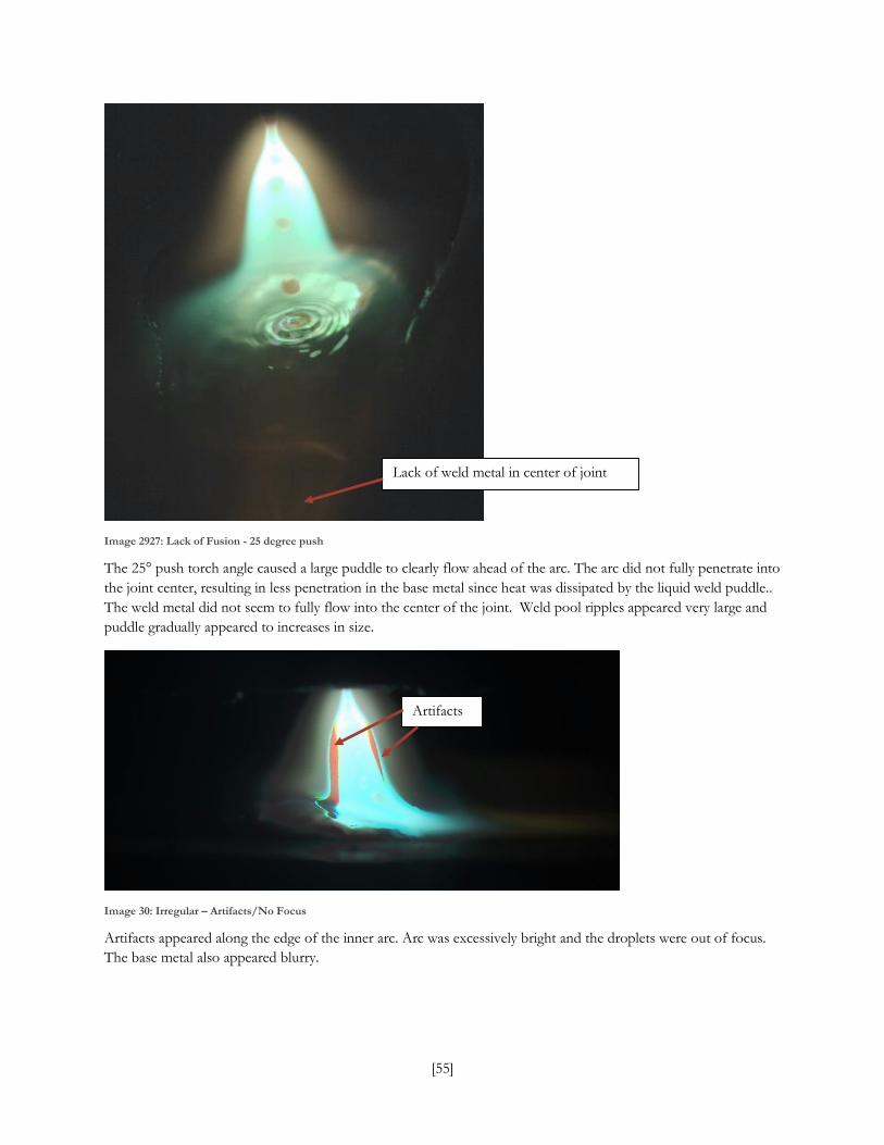
[55]
Image 2927: Lack of Fusion - 25 degree push
The 25° push torch angle caused a large puddle to clearly flow ahead of the arc. The arc did not fully penetrate into
the joint center, resulting in less penetration in the base metal since heat was dissipated by the liquid weld puddle..
The weld metal did not seem to fully flow into the center of the joint. Weld pool ripples appeared very large and
puddle gradually appeared to increases in size.
Image 30: Irregular – Artifacts/No Focus
Artifacts appeared along the edge of the inner arc. Arc was excessively bright and the droplets were out of focus.
The base metal also appeared blurry.
Lack of weld metal in center of joint
Artifacts

[56]
Image 31: Irregular - Leading, Joint Alignment
Grinder marks, wire length, tip to work distance, surface condition and any imperfections were very clearly visible
in this video. Torch alignment with center was displayed as the torch traveled at max speed along joint.
Image 32: Irregular - Trailing, Joint Alignment
Within the video from which this is derived, at 11 seconds torch traveled over a tack weld, and reached a prior
weld at 14 seconds. Grinder marks, wire length, tip to work distance, surface condition and any imperfections were
very clearly visible. Torch alignment with center was displayed as the torch traveled at max speed along joint.

[57]
Image 33: Irregular – Fluctuating Travel Speed
The torch travel speed changed from slow to max speed at an inconsistent rate. Droplet and weld pool size were
irregular and both became smaller while travelling faster.
Image 34: Irregular - Uncleaned, Plate
At 9 seconds, shiny floating particles were visible on the side of the solidifying weld edge behind the arc. The specs
resulted from impurities from the scale left on the plate.
Irregular weld pool size

[58]
Image 35: Irregular - High EV, no HDR
This video consisted of four frames at various exposures playing one after another, creating a flickering video
quality. Bead appearance was best at highest (brightest) exposure, droplet detail best at lowest (darkest) exposure.
It was possible to make out some droplet transfer details.

[59]
Video began with HDR off, then HDR was turned on from 7-18 seconds. At that point, the arc delay was set to
shortly before short-circuit occurs, it changed delay at 22 seconds to be at the point immediately before the short
circuit, and was changed again at 26 seconds to the short-circuiting point. Wire retraction was evident at the short-
circuit delay point. The surface tension created in the liquid metal as it was transferred through the electrode tip
could be observed. Weld pool solidification wass clearly visible.
Image 36: CMT No HDR

[60]
Image 3728: CMT - Fillet, HDR
Arc delay was set shortly before short-circuit occurred, and at 28 seconds the delay changed to the point right
before short-circuit. The arc size would slightly shift until 60 seconds, when the delay was set to be at the short-
circuit point. The weld pool size and orientation were distinguishable, and the base metal and joint conditions were
clearly visible.

[61]
Image 38: CMT no HDR
The video rapidly changed brightness levels when the arc was visible. Arc delay was set shortly before short-circuit
occurs, at 6 seconds the delay changed to the point closer to the short-circuiting point. The arc size decreased
slightly at 8 seconds, and at 13 seconds, the delay was set to the short-circuit point. The surface tension created in
the liquid metal as it was transferred through the electrode tip was observed. Weld pool solidification, size and
orientation were visible.