vlti as an imager for the full pionier...
TRANSCRIPT

PIONIERJB Le Bouquin, Lazareff, Berger, Zins, Traub, Millan-Gabet ...
for the full PIONIER teamVLTI as an imageruntil 2010: limited imaging capabilityCompetition is strong since 2006 (MIRC at CHARA)The gain from 3 to 4 T is not just “adding one telescope”4 telescopes (AT or UT) operational (superb VLTI group)Second generation instruments Gravity and Matisse to come around 2014
Niche for a visitor instrument
Friday, February 11, 2011

The Very Large Telescope InterferometerVLTI as an imageruntil 2010: limited imaging capabilityCompetition is strong since 2006 (MIRC at CHARA)The gain from 3 to 4 T is not just “adding one telescope”4 telescopes (AT or UT) operational (superb VLTI group)Second generation instruments Gravity and Matisse to come around 2014
Niche for a visitor instrument
UT1
UT2UT3
UT4
VLTI ELT
Friday, February 11, 2011

Context in 2009The context: milliarcsecond angular
resolution astronomyAstrophysical topics requesting marcsec astronomical resolution are numerous;
Optical long-baseline interferometry is an important tool
Current sensitivity sets restriction mostly to stellar physics but things are considerably improving
Imaging through aperture synthesis is requested to tackle complex phenomenons
Monnier et al Science 2007
Kloppenborg et al Nature 2010
The context: milliarcsecond angular resolution astronomy
Astrophysical topics requesting marcsec astronomical resolution are numerous;
Optical long-baseline interferometry is an important tool
Current sensitivity sets restriction mostly to stellar physics but things are considerably improving
Imaging through aperture synthesis is requested to tackle complex phenomenons
Monnier et al Science 2007
Kloppenborg et al Nature 2010Kloppenborg et al Nature 2010
• At LAOG:• Expertise and interest in imaging
interferometry• 4 telescopes IONIC beam combiner
available on-the-shelve: a result from several years of R&D
➡ Room for a fast project:The principle of PIONIER has been approved by STC at spring 2009.
• At VLTI• 4 telescopes already available since 2007• Instruments for 2 or 3 telescopes only• Next-generation projects planned for 2014
(at best, GRAVITY and MATISS)
Friday, February 11, 2011

The PIONIER proposition to ESOProposition made in 2009 by the LAOG :
• Build an instrument to combine the light of 4 telescopes of VLTI, using the visitor-instrument framework.
• On sky by end of 2010, with only few days of commissioning.
• Exploit this instrument with few weeks per semester over the 2011-2014 periods.
Funding and collaboration
• First: Local funding (UJF), and then national (CNRS, INSU, ANR)
• Camera from W. Traub and R. Millan Gabet (JPL).
• Integrated optics component is direct heritage from 10 years of local research in instrumentation (CNRS, INSU, ANR).
Friday, February 11, 2011

Description of the instrument
TipTilt
OPD
Parabola
Dichroic
Component
Optics + Prism
Friday, February 11, 2011

2 Benisty et al.: A 4-beam IO beam combiner with ABCD encoding
Fig. 1. Upper panel: theoretical design of the integrated optics 4-way beam combiner allowing pairwise combination and usingphase-shifting devices to produce 4 outputs in quadrature. We refer to each output using the index m,l,k. mlk is the kth output out of4, resulting from the combination of the beam m and l. The lower panel is a picture of a prototype that is 80mm long and 8mmwide.
complex. Finally, this technology o!ers the flexibility to easilyswitch beam combiners to adapt to a particular situation (e.g.target, number of telescopes).
Since the initial proposition by Kern et al. (1996), LAOGand its industrial partner LETI/CEA have been developing theuse of IO technology to interferometrically combine light beamsin optical waveguides lying on a solid substrate of a few cen-timeter (Kern et al. 1996; Malbet et al. 1999; Berger et al. 2000).This instrumental research program has consisted in designing,fabricating and characterizing all the IO building blocks requiredto build an astronomical interferometric beam combiner. Severalbeam combining schemes have been implemented and tested.Some of them have led to successful on-sky demonstrations suchas the VINCI/VLTI (2 telescopes) and IONIC3/IOTA (3 tele-scopes) instruments (Berger et al. 2003; LeBouquin et al. 2004;Kraus et al. 2005; Monnier et al. 2006a).
In the context of VLTI second-generation instrument studies,LeBouquin (2005) have studied the global e"ciency of a greatvariety of IO beam combiners. This study has concluded that oneof the most e"cient ways to combine four beams (e.g. 4 UT or 4AT) was to use a so-called “pairwise static ABCD” scheme (in-spired by the visibility estimator of Shao & Staelin (1977)). ThisIO circuit allows one to extract simultaneously four phase statesof the coherent signal independently for each of the six base-lines. We fabricated them (Labeye 2008), and in this paper, wepresent these new 4-beam combiners together with their com-plete laboratory characterization. They are probably the mostsophisticated astronomical beam combiners built to date. Thepaper is organized as follow: in Sect. 2, the technology and thespecific design of the beam combiners are described. In Sect. 3,we present the laboratory set up as well as the experimental pro-cedure; the characterization results are given in Sect. 4 and dis-cussed in Sect. 5.
2. The beam combiner: technology and designPrior to fabrication, the IO circuit was designed and numeri-cal computation simulating the propagation of an electromag-netic signal was carried out to determine the expected proper-ties in terms of flux routing. Each IO function was checked andits throughput and flux distribution were optimized numerically.
Fig. 2. Details of the beam combining function: for each inter-ferometric pair (e.g. [12]), one arm is shifted by 90! leading tofour outputs in quadrature (with phases written as !112 to !
412).
Combinations of beams occur in couplers that present two out-puts in phase opposition to maintain energy conservation. Byrecording the four phase states (ABCD-like, see the right fig-ure), one can retrieve the interferometric observables (amplitudeand phase of the fringes).
This step done, the simulation parameters were turned into tech-nological parameters and a photolithographic mask was fabri-cated.
LETI uses a silica-on-silicon technology to fabricate IO cir-cuits. This technological process requires several photolitho-graphic steps to etch di!erent layers. The beam combiners aremade by depositing alternatively 3 doped silica layers on asilicon substrate. The second layer is etched to define chan-nel waveguides and the other two layers constitute the opticalcladding. For the first time, the etching technology allows us tocompletely isolate each waveguide from the others (Labeye et al.2006). The produced beam combiners have been designed to op-erate in the atmospheric H band and more recently in the K band.
The so-called “pairwise static ABCD” beam combiner canbe described as follows. Each beam combiner is designed tohave 4 inputs and 24 outputs, allowing 6 interferometric pair-wise combinations, each one producing 4 phase-shifted outputswith a phase di!erence of 90!. For each injected beam, the lightpropagates through waveguides and is split in three in a tricou-pler (item (a) in Fig. 1) to enter the combining function (consti-
The IONIC 4 beam combinerInput fibers IONIC combiner (Benisty et al., A&A 498, 2009)
Prism and relay optic
Cam
era
IONIC is a collaboration between LAOG and CEA/LETI. This component is the result of more than 10 years of laboratory research (LAOG and LETI) and sky validations (IOTA, VLTI)... and numerous PhD students !
(where the real show takes place)
Friday, February 11, 2011

First lights and first fringes : October 25, 2010
• Commissioning : October, 20-24 2010 • Science since November 2010
(3 runs in P86)• 25nights scheduled in P87
• PIONIER has been commissioned and is working in the H-band
PIONIER at VLTI
Friday, February 11, 2011

Extension to the K-band
Dichroics
Component
Optics
Friday, February 11, 2011

Extension to the K-band• ANR EXOZODI
• Dichroic (15 keuros) + travels ?Already ordered.
• Postdoc position related to FLUOR/PIONIER observations+ observing missions
• Other aspects
• Component (30 keuros)One already available from internal research (not so good transmission). Looking for a new one
• Optics (10 keuros)From other funding of PIONIER, design on-going.
• Timeline for K-band implementation
• Commissioning in October 2011 (1 week)
• So first proposals in March 2011
• On-going discussion with ESO to secure the comm. time.
Friday, February 11, 2011

PIONIER ... some picturesJB Le Bouquin, Lazareff, Berger, Zins, Traub, Millan-Gabet ...
for the full PIONIER teamVLTI as an imageruntil 2010: limited imaging capabilityCompetition is strong since 2006 (MIRC at CHARA)The gain from 3 to 4 T is not just “adding one telescope”4 telescopes (AT or UT) operational (superb VLTI group)Second generation instruments Gravity and Matisse to come around 2014
Niche for a visitor instrument
Friday, February 11, 2011

Integration at LAOG : January - September 2010
Cryogeny
Optics
Two interventions on the camera dewar ... stress !!
Electronic
Software / ControlProject Management
+ Administration
Friday, February 11, 2011
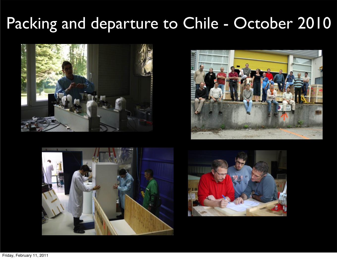
Packing and departure to Chile - October 2010
Friday, February 11, 2011

Installation on site : October, 20-24 2010
Friday, February 11, 2011

PIONIER in the press
108 December 2010 Physics Today www.physicstoday.org
A PIONIERing interferometerIn a grand display of astrophotonics, the light from four telescopesat the Very Large Telescope Interferometer (VLTI) in Chile was com-bined in late October for the first time, by the Precision Integrated-Optics Near-infrared Imaging ExpeRiment (PIONIER). The visitinginstrument, developed at the Laboratoire d’Astrophysique deGrenoble (LAOG) in France, complements the two existing VLTIinstruments that combine light from two and three telescopes.
Before even reaching PIONIER, the light paths from the four 1.8-meter auxiliary telescopes at the VLTI had to be controlled toless than a micron. Each of PIONIER’s four alignment units, seenabove in the foreground, focuses one of the incoming VLTI beamsinto an optical fiber. The fibers channel the light into the heart ofthe instrument: an integrated optics beam combiner, developed atLETI, a French Atomic Energy Commission laboratory, in collabora-
tion with LAOG. Housed under the folded metal cover to the left of the alignment units, the combiner, smaller than a credit card,interferes each beam with all the others (see the inset). The 24 combiner outputs are then focused onto a detector in the brasscryostat.
The interference output of PIONIER will have the resolving power of a virtual telescope some 100 meters across. The first imagesare anticipated in early 2011. Among the topics that PIONIER will study are protoplanetary and debris disks, hot Jupiters, and stellarsurfaces. (Photo courtesy of Bernard Lazareff/LAOG/OSUG/UJF/CNRS and the European Southern Observatory; inset courtesy ofLAOG/UJF and CEA/LETI, photo © CNRS Photothèque/Emmanuel Perrin.)
To submit candidate images for Back Scatter, visit http://www.physicstoday.org/backscatter.html.
Friday, February 11, 2011

PIONIER - DRSJB Le Bouquin
for the PIONIER team
Friday, February 11, 2011

Preparation and Observation : an ESO look and feel
• PIONIER is visitor instrument, and therefore is not obliged to follow the ESO flow... but we tried to stick on it !
• Use p2pp, BOB, VLT-software...
• Observations at Paranal are supported by an ESO astronomer, in charge of VLT-I only (actually JP. Berger).
• ESO pay one travel from Europe per run.
• Limited support from ESO for the hardware side (N2 filling only), no intervention on the instrument.
• PIONIER observer should be aware of all aspect of observation: alignment, operation, drs, .... better to be 2 persons.
Control panels
Happy observer
Friday, February 11, 2011

PIONIER is in the data-flow of optical interferometry
ESO Proposal(next is March, 30)
Observations(visitor-mode only)
Model fitting orImage reconstruction
aspro2
Data Reduction(automatic)
PIONIER is included/compatible with the tools from JMMC.
LITpro
searchCalMIRA ?
Image reconstruction algorithm with user-interface... ??
Friday, February 11, 2011

Existing Pipeline• Data are transferred from wpnr to the laptop
of the observer.
• Current pipeline process the data from RAW until final, calibrated, science-ready OIFITS files (IAU standard for interferometry).
• Kappa-matrix, dark and fringe data are associated automatically.
• Diameters of calibration stars are recovered automatically from the JMMC catalogue=> almost no-user interaction.
• Run in real-time : science-ready data can be analyzed ~10min after observation=> real-time decisions.
• The spectral calibration is currently not (fully) implemented in the pipeline.
0.0
0.5
1.0
0.0
0.5
1.0
0.0
0.5
1.0
0.0
0.5
1.0
0.0
0.5
1.0
0.1 0.2 0.30.0
0.5
1.0
MJD ! 55532
E0
!G
0H
0!
E0
H0
!G
0H
0!
I1I1
!E
0I1
!G
0
Tranfer!Function Vis2 (black) and Scientific Obs. (colors)averaged in the range =[1.7,1.73]µm
(color=target, symbol=setup)
raw data
transfer-function
OIFITS file
Friday, February 11, 2011

Some diameters
0. 1. 2. 3. 4. 5.10+7
0.5
0.6
0.7
0.8
0.9
1.0
u
v
spatial frequency in 1/rad
squa
red
visi
bilit
y (V
IS2)
0. 1. 2. 3. 4. 5.10+7
0.2
0.4
0.6
0.8
1.0 u
v
spatial frequency in 1/rad
squa
red
visi
bilit
y (V
IS2)
80-Cet - M0IIIH=1.43.02 mas⇒ 3.017 +/- 0.01 mas
HIP114421 - K2IIIH=1.732.28 mas⇒ 2.175 +/- 0.02mas
0. 1. 2. 3. 4. 5.10+7
0.85
0.90
0.95
1.00
1.05 u
v
spatial frequency in 1/rad
squa
red
visi
bilit
y (V
IS2)
SAO 111120 - G5VH=3.00.96 mas⇒ 0.77 +/- 0.1mas
© LITpro from JMMC
Friday, February 11, 2011

Precision visibility: work in progress
0.0
0.5
1.0
0.0
0.5
1.0
0.0
0.5
1.0
0.0
0.5
1.0
0.0
0.5
1.0
0.1 0.2 0.30.0
0.5
1.0
MJD ! 55532
E0
!G
0H
0!
E0
H0
!G
0H
0!
I1
I1
!E
0I1
!G
0
Tranfer!Function Vis2 (black) and Scientific Obs. (colors)averaged in the range =[1.7,1.73]µm
(color=target, symbol=setup)
Base
line
1Ba
selin
e 2
Base
line
3
Time (~8h)
PIONIER uses a FLUOR-like method to form and analyze the fringes (scanning method), and therefore it should achieve a similar precision on v2 ~ 1%.
Current performances are at ~5% when everything is OK, and sometimes ~20%.
First tests show that PIONIER is not affected by biases related to low SNR.
Possible origins of limitations:• vibrations in the PIONIER piezo
(being investigated)• vibrations in the ATs• detector weird effects...• next runs are focused on finding
a setup for best calibration.
Friday, February 11, 2011

Detector is not fully understood
−50
0
50
−100
−50
0
50
100
500 1000 1500
−50
0
50
500 1000 1500
−100
−50
0
50
100
−100
−50
0
50
100
500 1000 1500
−50
0
50
500 1000 1500
High SNR data,good quality
High SNR data,detector saturation ?
PICNIC camera is used in a special way (non-destructive up-the-ramp mode), in order to achieve sufficient frame rate and good noise... but we are strongly limited by the detector dynamic.
Friday, February 11, 2011

PIONIER DRS - summary• PIONIER has a fully integrated data-flow, from observation
preparation to data-analysis.
• Current version of the DRS is a “robust but non-accurate” way. It is not tuned for high visibility.
• We may face issues that are not only DRS limitation : work should be done in the data acquisition chain (detector readout mode) and perhaps hardware (piezo).
• Similar concept than FLUOR, so the PIONIER DRS can (more) benefit from experience learned at FLUOR... we should discuss !!
• Next PIONIER run (in few days) is dedicated to define the best instrumental setup to make precise visibility.
Friday, February 11, 2011