voc-free wave soldering - selas elektronik ve Çevre ... · voc-free flux is build on water soluble...
TRANSCRIPT

Voc-free wave soldering
Harry Trip, Manager Technical Support

Wave solder flux systems
0%
10%
20%
30%
40%
50%
60%
70%
80%
90%
100%
Alcohol based VOC-Free Low-VOC VOC-azeotrope
Global Composition Fluxes
Filmformers
Activators
Di-Water
Alcohols
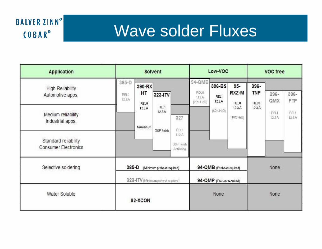
Wave solder Fluxes

The perfect flux:
• Should solder everything• Should be environmental friendly (VOC-Free)• Should leave no residues• Should meet all safety standards (halide free?)• Should prevent all solder balls• Should prevent all shorts• Should not cause any ICT problems• Should make nice and shiny solder joints• Should have a pleasant or no odor• Should not pollute the wave solder machine• Should not be more expensive than current voc• Please add more……..

Main topics in new flux development
• VOC-free• Alternatively Low-Voc • Halide free (IPC L0)• Stronger fluxes to eliminate bridging, but still within
residue safety standards• Anti solder balling solution• Generally less visual residues on all resists• Special selective soldering fluxes

L1 Halides � < AcidNo Halides � > Acid
Residues, REL-0 or REL1
Visible residues do not necessarilymean corrosive residues
Acids in residue ����Hygroscopic effect ����Corrosion risk ����
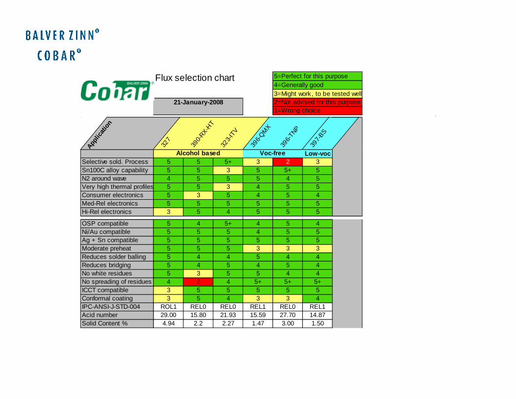
Flux selection chart 5=Perfect for this purpose4=Generally good3=Might work , to be tested well2=Not advised for this purpose1=Wrong choice
21-January-2008
Applic
atio
n
327
390-
RX-HT
323-
ITV
396-
QM
X
396-
TNP
397-
BS
Alcohol based Voc-free Low-vocSelective sold. Process 5 5 5+ 3 2 3Sn100C alloy capability 5 5 3 5 5+ 5N2 around wave 4 5 5 5 4 5Very high thermal profiles 5 5 3 4 5 5Consumer electronics 5 3 5 4 5 4Med-Rel electronics 5 5 5 5 5 5Hi-Rel electronics 3 5 4 5 5 5
OSP compatible 5 4 5+ 4 5 4Ni/Au compatible 5 5 5 4 5 5Ag + Sn compatible 5 5 5 5 5 5Moderate preheat 5 5 5 3 3 3Reduces solder balling 5 4 4 5 4 4Reduces bridging 5 4 5 4 5 4No white residues 5 3 5 5 4 4No spreading of residues 4 2 4 5+ 5+ 5+ICCT compatible 3 5 5 5 5 5Conformal coating 3 5 4 3 3 4IPC-ANSI-J-STD-004 ROL1 REL0 REL0 REL1 REL0 REL1Acid number 29.00 15.80 21.93 15.59 27.70 14.87Solid Content % 4.94 2.2 2.27 1.47 3.00 1.50
Alcohol based Voc-free

What is a dendrite
A dendrite in metallurgy is a characteristictree-like structure of crystals
When a voltage is applied between an anode and cathode, a metal dendrite grows from the cathode through the ion conductor towards the anode

Dendrites

What makes corrosion or dendrites in soldering ?
A combination of:1. Metal2. Ionic contamination or ion conductivity (acids,
halides , minerals (also on finger prints!)3. Oxygen (air)4. Moisture (air)5. Polarity, voltage6. Temperature

What is VOC
• Volatile Organic Compound• Definition:
According to the American EPA (Environmental Protection Agency): “A solvent system with a vapor pressure of less than 0.1 mm Hg (Mercury)”.
Consequently this means that virtually no gas will escape out of the product at room temperature.

Why voc-free fluxes?
59,5
60
60,5
61
61,5
62
62,5
63
1900 1915 1922 1931 1942 1953 1961 1968 1975 1982 1990
Years
Fa
hre
nhe
it
17.2
16.9
16.7
16.4
16.1
15.8
15.6
15.3
Ce
ntig
rade
s
Global surface (combined land & ocean) temperatures

Voc-free fluxes eliminate:
• Process control problems due to solvent evaporation
• Thinner consumption
• Waste disposal problems
• Greenhouse effect considerations
• Fire risk
• Restrictions and extra costs for transport, storage and handling
So why are not all of us onvoc-free flux already ?

The contras of VOC-Free Fluxes
VOC-Free flux is build on water soluble = hygroscopic ingredients
• Risk for corrosion if flux is not properly neutralized by the heat of the wave (flux under pallets, on topside or just too much flux applied)
• Highest residue safety standards and widest process window still with alcohol based fluxes (alcohol or low-voc)
• Higher risk for solder balling (less choice in ingredients)

VOC-free versus alcohol based
• Acid in IPA is less active as same amount in H2O (water mix much more polar)
• All ingredients must be water soluble for stable solution• There for much smaller range of possible ingredients• Uncured residues are hygroscopic• H2O is more mobile than alcohol• IPA spreads better than H2O (surface tension)

Are there absolute safe flux residues
• Hard to say, flux can help growing dendrites but the milder the flux, the less the risk.
• Dendrites can even grow without flux• All depends of moisture level, temperature, pitch, voltage, pcb contamination and flux formulation
• Special high-end flux can greatly reduce risk.

Dendrite formation No flux. Pcb contaminated

Low-voc?
Maybe best of both worlds!70% emission reduction usually enough to meet demands of local or national authorities(Cobar 397-BS)

Solder balls Solder balls

Solder balls
Random or Systematic solder balls ???How are they formed ???What is accepted (acc. IPC-A-610 D) ???⇒Minimum electrical distance⇒Must be fixed in the flux residue
Solder balls

Solder balls
Parameters effecting solderballs
Atmosphere (Nitrogen)
4%
Storage conditions (humidity)
11%
Solder6%
Solder resist51%
Flux17%
Machine settings
11%
Resource:
The solderball problem. Research and results
H. Bell – Rehm / R. Zajitschek – Siemens VDO

Solder balls
Random solder balls
Solder will adhere to metalized parts
Gravity bigger as Surface Tension
Snapping action downwards
Micro ball propelled toward board
Pictures courtesy of: TKB-4u.com
Results in random solder balls,
No defined place, size differs from one ball to another
Pictures
Courtesey of TKB-4u.com

Solder balls (4)
Systematic solder balls
PCB
Solder
PCB
Solder
PCB
Solder
Soldering action Solder softens the solder resist
Longer contact time > solder adhesion to resist
Solder has low cohesion and sticks to resist
Results in Systematic solder balls,
Defined place, sizes on one component almost all equal.
PCB
Solder
PCB
Solder

Solder balls (5)
Solder resist (~51%)
Surface structure of solder resist
Tg (Glass transition temperature) of solder resistSolder resist gets soft above Tg and will
promoteattachment of solder and therefore solder
balls
Rough surface has smaller attach area as smooth surface, subsequently there will be less solder ball formation

Process is more critical
Important parameters:
• Flux volumes
• Preheat
• Design of solder pallets
• Wave set-up
Voc-free implementation

VOC-Free introduction Impacts
1. Application of flux by fluxing unit
2. Wetting of flux of non-metallic surfaces (solder resist)
3. Preheating of flux
4. Removal of oxides from metallic surfaces (pads & leads)
5. Post-solder residues
6. Maintenance of wave solder equipment

Low viscosity and the need for precise application of VOC-Free fluxes require nozzle spray fluxing
• General rule: Use as less as possible flux
• Optimize the spray pattern as much as possible
• Too much flux can cause:
- board contamination => corrosion risk
- formation of solder balls
- waste of flux
- equipment contamination
- skipped joints by flux accumulation in capillaries
Flux Application

Wicking in THT
Unsufficient Pressure or too
much flux

Parameters
Spray Pressure
Spray PatternSpray
Range
Spray Distance Spray
Angle
Note: Big difference between 45 and 60 degrees cap!

Board Transport in SolderingMachine
Finger conveyorPallets: design adjustments may be necessary!
Old pallets may accumulate water. This will come out violently when assembly is in the wave!
x

Preheating VOC-Free Fluxes
• FC may blow off the flux when applied in 1st preheat stage
• Water has a different IR-wave length than
IPA and Ethanol
• Water has a lower vapor pressure
• Water has a different boiling behavior (ST)

- of VOC-Free Flux
Absorbance of H2O

Preheat Requirements• IR-heat direct after fluxer
• Boiling water impacts efficiency of volatilization
• Efficient absorbance of IR by H2O in medium IR-wave length
• Peak temp. S-S pcb: 90-100 C, T-H pcb/L.F.: 115-130 C. topside (lead-free process)
medium-wave length IR +
emission temperature of
approx. 300 oC (max. 400)
1st zone
forced
convection
(or I.R.)
Other zone(s)
forced
convection
(or I.R.)
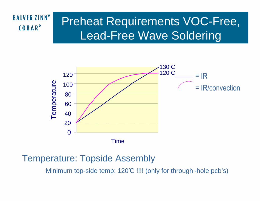
Preheat Requirements VOC-Free, Lead-Free Wave Soldering
Temperature: Topside AssemblyMinimum top-side temp: 120°C !!!! (only for through -hole pcb’s)
= IR
= IR/convection
0
20
40
60
80
100
120
Time
Tem
pera
ture
130 C120 C

Components & VOC-Free Fluxes
Prevent water penetration and residues:
• VOC free ingredients (solids) are water soluble.
• Uncured residues stay acidic and are hygroscopic
• Water and acid = highly corrosive
• Using sealed components
• Proper fluxer setting
• Using temporary masks or tapes
Selective / Pallet Soldering issues

(Selective) Pallet Soldering (1)
Flux
PCB
Pallet
Flux residues between pallet and PCB
Flux Preheat phase Soldering phase
Wetting Wicking Drain phase
Cooling
Evaporate Activation Solidify

(Selective) Pallet Soldering (2)
Disturbance of the wave characteristics
PCB
Open jointInsufficient TH Filling
Flux Preheat phase Soldering phase
Wetting Wicking Drain phase
Cooling
Evaporate Activation Solidify

What happens with the flux next to the wave?

Selective & Pallet Soldering (4)
For these applications, the best advise is:Alcohol or low-voc flux
Better not voc-free

Thanks for your attentionBedankt voor uw aandachtVielen Dank für Ihre AufmerksamkeitDziekuje za uwageGrazie per l’attenzioneGracias por su amabilidadHorosho pa menya ......Tack för din uppmärksamhetGohairyo arigatou gozaimasu Xie xie ni di zhu yi
