vocera hl7 adapter configuration guide
TRANSCRIPT
Vocera HL7 Adapter Configuration GuideVersion 1.5.0

ii VOCERA HL7 ADAPTER CONFIGURATION GUIDE
Notice
Copyright © 2002-2021 Vocera Communications, Inc. All rights reserved.
Vocera® is a registered trademark of Vocera Communications, Inc.
This software is licensed, not sold, by Vocera Communications, Inc. (“Vocera”). The reference text of the license governing this software can be found at https://www.vocera.com/legal/. The version legallybinding on you (which includes limitations of warranty, limitations of remedy and liability, and other provisions) is as agreed between Vocera and the reseller from whom your system was acquired and is availablefrom that reseller.
Certain portions of Vocera’s product are derived from software licensed by the third parties as described at https://www.vocera.com/legal/.
Microsoft®, Windows®, Windows Server®, Internet Explorer®, Excel®, and Active Directory® are registered trademarks of Microsoft Corporation in the United States and other countries.
Java® is a registered trademark of Oracle Corporation and/or its affiliates.
All other trademarks, service marks, registered trademarks, or registered service marks are the property of their respective owner/s. All other brands and/or product names are the trademarks (or registeredtrademarks) and property of their respective owner/s.
Vocera Communications, Inc.www.vocera.comtel :: +1 408 882 5100fax :: +1 408 882 5101
Last modified: 2021-05-01 09:17
ADP-hl7-150-Docs build 323

iii VOCERA HL7 ADAPTER CONFIGURATION GUIDE
Contents
Understanding a Vocera HL7 Adapter Configuration................................................................................................................ 4
Viewing the Vocera HL7 Adapter Requirements...........................................................................................................................................4
Using Ports in Adapter Guide Requirements........................................................................................................................................... 5
Configuring a Vocera HL7 Adapter................................................................................................................................................. 6
Using the Additional Functionality in the Vocera HL7 Adapter....................................................................................................................13
Understanding HL7 Messaging Specifications............................................................................................................................................16
Viewing HL7 Message Logs on a Vocera Platform Appliance.................................................................................................................... 23
Understanding the Vocera HL7 Adapter Rules......................................................................................................................... 25
Understanding Adapter Installation............................................................................................................................................... 29
Accessing Supported Adapters.................................................................................................................................................................. 29
Recreating a Repository............................................................................................................................................................................. 30
Installing an Adapter................................................................................................................................................................................... 31
Practicing an Adapter Installation............................................................................................................................................................... 31
Navigating the Vocera Platform Adapters...................................................................................................................................33
Editing an Adapter......................................................................................................................................................................................35
Creating a New Adapter.............................................................................................................................................................................35
Saving an Adapter......................................................................................................................................................................................37
Deactivating an Adapter............................................................................................................................................................................. 37
Removing an Adapter.................................................................................................................................................................................38
4 VOCERA HL7 ADAPTER CONFIGURATION GUIDE
Understanding a Vocera HL7 Adapter Configuration
Configure the Vocera HL7 Adapter to enable communication with other HL7-capable systems via the Vocera Platform.
Adapters send information to and receive information from Vocera Platform, as well as monitor and collect data. Each adapter is configuredto allow Vocera Platform to communicate with a specific type of resource and any devices that resource may control. For example, theVocera HL7 Adapter (Health Level 7) is used to connect with an existing HL7 capable system. By creating multiple Vocera HL7 Adapterinstances, an installation can allow for communication with different departments and system types within a single facility.
A Vocera HL7 Adapter is used to communicate with any other system or database that is HL7 capable. It brings the pertinent information,such as lab results, to Vocera Platform and stores those events in the Data Manager. This information is then potentially later sent to therecipient database of that HL7 message based upon Appliance configurations. The content of the message varies depending on the HL7configuration in the Appliance, but any HL7 message may include data such as patient information and history, lab results, and radiologyreports.
At least one connection must be configured, either inbound or outbound. An inbound connection brings messages from an HL7 server tothe Vocera Platform system, while an outbound connection allows Vocera Platform to communicate to the HL7 server.
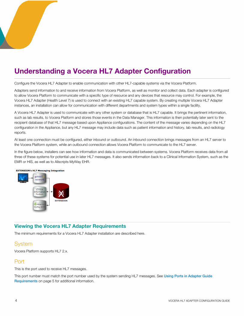
In the figure below, installers can see how information and data is communicated between systems. Vocera Platform receives data from allthree of these systems for potential use in later HL7 messages. It also sends information back to a Clinical Information System, such as theEMR or HIS, as well as to Allscripts MyWay EHR.
Viewing the Vocera HL7 Adapter RequirementsThe minimum requirements for a Vocera HL7 Adapter installation are described here.
SystemVocera Platform supports HL7 2.x.
PortThis is the port used to receive HL7 messages.
This port number must match the port number used by the system sending HL7 messages. See Using Ports in Adapter GuideRequirements on page 5 for additional information.

UNDERSTANDING A VOCERA HL7 ADAPTER CONFIGURATION
5 VOCERA HL7 ADAPTER CONFIGURATION GUIDE
Using Ports in Adapter Guide Requirements
Some ports are not recommended for use when configuring an adapter.
Warning: Do NOT use the following ports for an adapter configuration: 22, 8888, 8443, 1099, 52517, 3700, 3820, 3920, 4848,7676, 8080, 8181, 8686, 13579, 36123, 41776, 52071, 5432, 80, 443, 25

6 VOCERA HL7 ADAPTER CONFIGURATION GUIDE
Configuring a Vocera HL7 Adapter
Description of the settings that enable direct communication between the Vocera HL7 Adapter and the Vocera Platform.
Select an empty field and begin typing, or select an existing value and type over it. To keep an existing value, do not edit that field.
1. Access the Vocera Platform Web Console and navigate to the adapters.
See Navigating the Vocera Platform Adapters on page 33 for instructions.
2. Select New Adapter in the Action menu, or select an adapter you wish to configure and then select Edit, to display the configurationfields. The configuration fields are the same for new and existing adapters.
3. Navigate to the New Adapter option, or navigate to an existing adapter to edit. See Creating a New Adapter on page 35 andEditing an Adapter on page 35 for instruction as needed.
The configuration fields are the same for new and existing adapters.

CONFIGURING A VOCERA HL7 ADAPTER
7 VOCERA HL7 ADAPTER CONFIGURATION GUIDE
4. Complete the General Settings configuration fields as described in the table.
General Settings Configuration Fields Description
Component Name Click the Component Name field to display a list of the systems anddevices that the Vocera Platform currently supports. Select the name ofthe adapter to create.
Reference Name Enter a short descriptive name in the Reference Name field to uniquelyidentify an adapter instance. It may demonstrate the adapter function orother information; for example, Production adapter may differentiate a liveadapter from a development or "sandbox" adapter.

CONFIGURING A VOCERA HL7 ADAPTER
8 VOCERA HL7 ADAPTER CONFIGURATION GUIDE
General Settings Configuration Fields Description
Enabled Select the Enabled checkbox to allow the Vocera Platform to use the newadapter. The Vocera Platform ignores the adapter if this option is disabled.
Time Zone Enter the time zone to use when processing dates and times without atime zone. This setting controls how date/time values in messages areinterpreted and encoded.
5. Complete the Outbound Connection configuration settings.
Outbound Connection Configuration Fields Description
Outbound Connection Vocera Platform can use an outbound connection to communicate with anHL7 server for processing outbound messages. Configure the outboundconnection with the following information.At least one connection, inbound or outbound, must be configured for theVocera HL7 Adapter to function. If Outbound Connection is unchecked,an inbound connection and message type are created in the system bydefault.When sending outbound HL7 messages, a version of 2.3 is used bydefault in the message header of each message sent. If required, theversion sent may be adjusted by an implementation specialist via aconfigurable interface property.
Message Format Select the message format (ER7 or XML) that this facility will use for thisoutbound connection. This field is required.
Server Name Enter the host name or IP address of the server to which the outboundconnection will connect. This field is required and must be a valid servername for an outbound connection.
Port Enter the server port on which HL7 messages and acknowledgments aretransmitted. This field is required and must be a number between 1 and65535.
6. Complete the Inbound Connections configuration settings.
Configure one or more connections for processing inbound HL7 messages. At least one connection, inbound or outbound, must beconfigured for the Vocera HL7 Adapter to function. If Outbound Connection is unchecked, an inbound connection and message typeare created in the system by default.

CONFIGURING A VOCERA HL7 ADAPTER
9 VOCERA HL7 ADAPTER CONFIGURATION GUIDE
Click Add to create an inbound connection, and the configuration fields shown below display. Click to expand an existing connectionand edit the configuration, or click Add to create additional inbound connections to support additional HL7 servers.
Click Remove to delete a specific inbound connection. The last inbound connection can only be removed if there is an outboundconnection; the Remove option is not displayed in this event.
Inbound Connections Configuration Fields Description
Reference Name Enter a descriptive name for the collection of settings that define thisconnection.
Message Format Select the message format (ER7 or XML) that this facility will use for thisinbound connection. This field is required.
Port Enter the server port on which HL7 messages and acknowledgments aretransmitted. This field is required and must be a number between 1 and65535.It is recommended that each connected system be assigned to a separateport. The number for threads available for processing inbound messagesis proportional to the number of available ports, and the reporting ofinactivity is also by port.The thread pool that handles connections and the initial reading ofmessages has a limited number of threads per inbound connection. It isdesigned to handle no more than two actual network connections perconfigured "inbound connection", which implies each connecting systemshould have a separate inbound connection configured.In addition, detection of idle input is done separately for each configuredinbound connection. If multiple systems connect to the same inboundconnection port and one of them gets into a bad state where it is nolonger sending messages, it would not be noticed if the other systems onthe same inbound connection continue processing successfully.
Suppress Acknowledgments Select this checkbox to prevent the adapter from sending HL7acknowledgments in response to messages on inbound connections. Thisoption may be useful for older versions of the Philips patient monitoringsystems.
Message Timeout Enter the number of minutes expected to elapse between messages. Thevalue must be a number between 1 and 10000. When this timeout periodis exceeded, audit event 600 is generated to report that the connection isidle.
Report Non-Matching Messages as Audit Events Check this box if the system should log an audit event when a receivedmessage does not match a message definition.
Report Applied Preprocessing Rules Check this box if the system should log an audit event when apreprocessing rule changes a message's content.
7. Complete the Preprocessing Rules configuration settings.
Preprocessing rules are used to modify non-standard received messages before they are matched against configured messagedefinitions. Configure one or more preprocessing rules.
The preprocessing rules are applied, in listed order, when a message is first received on an inbound connection as follows:
1. A message is received.
2. Each subsequent incidence of the received message that matches the regular expression is replaced by the replacement string,creating a new message.
3. Repeat steps a and b for each preprocessing rule in listed order on the new message.
4. Match the new message against the configured message definitions.
Expand an existing preprocessing rule to edit the configuration, or click Add to create additional preprocessing rules. Click Remove todelete a specific preprocessing rule.
CONFIGURING A VOCERA HL7 ADAPTER
10 VOCERA HL7 ADAPTER CONFIGURATION GUIDE
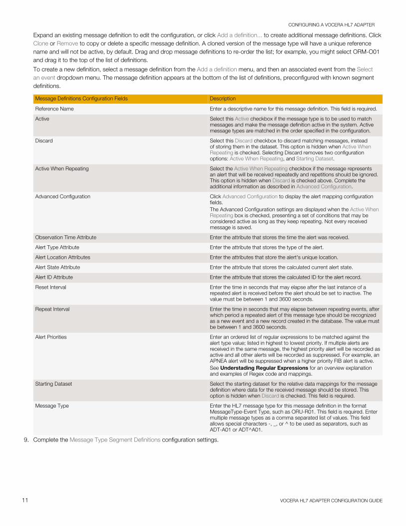
Preprocessing Rules Configuration Fields Description
Purpose Enter the purpose of the preprocessing rule. This field is required. Thepurpose should concisely describe the rule and be easily understood.
Active Select the Active checkbox to allow this preprocessing rule to be used inthe facility's HL7 implementation.
Regex Enter a regular expression to match against received messages for thispreprocessing rule. This field is required, and must be a valid regularexpression.See Understading Regular Expressions for an overview explanationand examples of Regex code and mappings.
Note: To prevent high CPU loads, each regular expression usedin the appliance is limited to run for five seconds. If the regularexpression's processing time exceeds this threshold, an auditevent is generated and the regex fails to match results.
Replacement String Enter the replacement string of a preprocessing rule to be substituted foreach match of the regular expression. This field is required.
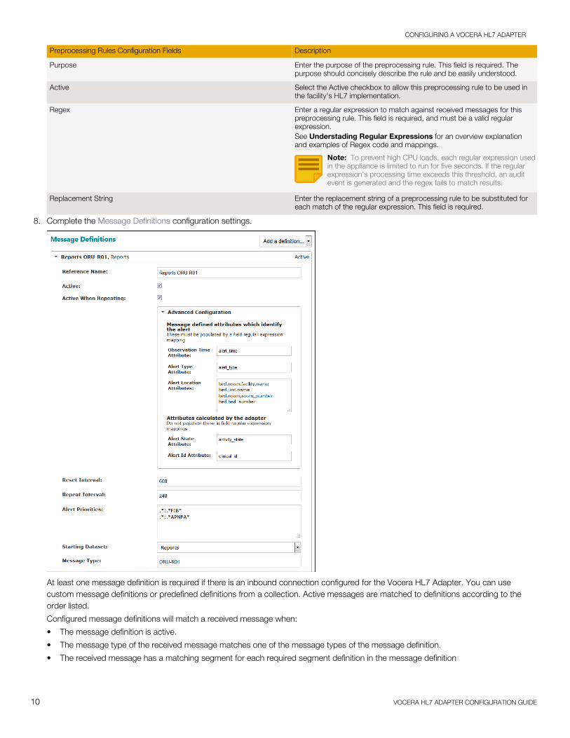
8. Complete the Message Definitions configuration settings.
At least one message definition is required if there is an inbound connection configured for the Vocera HL7 Adapter. You can usecustom message definitions or predefined definitions from a collection. Active messages are matched to definitions according to theorder listed.
Configured message definitions will match a received message when:
• The message definition is active.
• The message type of the received message matches one of the message types of the message definition.
• The received message has a matching segment for each required segment definition in the message definition
CONFIGURING A VOCERA HL7 ADAPTER
11 VOCERA HL7 ADAPTER CONFIGURATION GUIDE
Expand an existing message definition to edit the configuration, or click Add a definition... to create additional message definitions. ClickClone or Remove to copy or delete a specific message definition. A cloned version of the message type will have a unique referencename and will not be active, by default. Drag and drop message definitions to re-order the list; for example, you might select ORM-O01and drag it to the top of the list of definitions.
To create a new definition, select a message definition from the Add a definition menu, and then an associated event from the Selectan event dropdown menu. The message definition appears at the bottom of the list of definitions, preconfigured with known segmentdefinitions.
Message Definitions Configuration Fields Description
Reference Name Enter a descriptive name for this message definition. This field is required.
Active Select this Active checkbox if the message type is to be used to matchmessages and make the message definition active in the system. Activemessage types are matched in the order specified in the configuration.
Discard Select this Discard checkbox to discard matching messages, insteadof storing them in the dataset. This option is hidden when Active WhenRepeating is checked. Selecting Discard removes two configurationoptions: Active When Repeating, and Starting Dataset.
Active When Repeating Select the Active When Repeating checkbox if the message representsan alert that will be received repeatedly and repetitions should be ignored.This option is hidden when Discard is checked above. Complete theadditional information as described in Advanced Configuration.
Advanced Configuration Click Advanced Configuration to display the alert mapping configurationfields.The Advanced Configuration settings are displayed when the Active WhenRepeating box is checked, presenting a set of conditions that may beconsidered active as long as they keep repeating. Not every receivedmessage is saved.
Observation Time Attribute Enter the attribute that stores the time the alert was received.
Alert Type Attribute Enter the attribute that stores the type of the alert.
Alert Location Attributes Enter the attributes that store the alert's unique location.
Alert State Attribute Enter the attribute that stores the calculated current alert state.
Alert ID Attribute Enter the attribute that stores the calculated ID for the alert record.
Reset Interval Enter the time in seconds that may elapse after the last instance of arepeated alert is received before the alert should be set to inactive. Thevalue must be between 1 and 3600 seconds.
Repeat Interval Enter the time in seconds that may elapse between repeating events, afterwhich period a repeated alert of this message type should be recognizedas a new event and a new record created in the database. The value mustbe between 1 and 3600 seconds.
Alert Priorities Enter an ordered list of regular expressions to be matched against thealert type value; listed in highest to lowest priority. If multiple alerts arereceived in the same message, the highest priority alert will be recorded asactive and all other alerts will be recorded as suppressed. For example, anAPNEA alert will be suppressed when a higher priority FIB alert is active.See Understading Regular Expressions for an overview explanationand examples of Regex code and mappings.
Starting Dataset Select the starting dataset for the relative data mappings for the messagedefinition where data for the received message should be stored. Thisoption is hidden when Discard is checked. This field is required.
Message Type Enter the HL7 message type for this message definition in the formatMessageType-Event Type, such as ORU-R01. This field is required. Entermultiple message types as a comma separated list of values. This fieldallows special characters -, _, or ^ to be used as separators, such asADT-A01 or ADT^A01.
9. Complete the Message Type Segment Definitions configuration settings.

CONFIGURING A VOCERA HL7 ADAPTER
12 VOCERA HL7 ADAPTER CONFIGURATION GUIDE
At least one segment definition must be provided for a message definition. A segment definition will match a received segment when:
• The name of the received segment matches the name of the segment definition.
• The received segment has each field matching the regex if it is required to match.
• A repeated segment matches if any of the repeated segments match.
Note: All HL7 messages build their MSH segments with an internal segment definition. All existing MSH segment definitions areignored.
Click Add Segment Definition to create additional segments. A New Segment Definition expansion box will appear at the bottom of thesegment list. Drag and drop segment definitions to re-order the list; for example, you might select the New Segment Definition and dragit to the top of the list for configuration.
Expand an existing segment definition to edit the configuration. Links at the bottom of this field are provided to clone or remove asegment definition, remove the last field definition, and add a field definition.
Message Type Segment Definitions Configuration Fields Description
Name Enter the HL7 name for this segment definition. This field is required.
Description Enter a description of the new segment created for this messagedefinition. This field is optional.
Active Select this checkbox if the segment definition is active for this adapter.
Required Select this checkbox if the segment definition must be matched for itsmessage definition to be matched.
Dataset Mapping Select an option from the dropdown menu that will determine how to mapthe field data from segments matching this definition. Select to add thedata to the parent record (taking into account segment groups), to createseparate parent records for each matching segment, or to create separatelinked child records for each matching segment.The dropdown menu options display as follows:• Add to parent record• Parent record per segment• Linked child record per segment
Link To The Link To field is displayed when the "Linked child record per segment"option is selected in the Dataset Mapping dropdown menu.Enter the name of a link to a dataset, relative to the message definition'sstarting dataset, in which to store attribute mappings.

CONFIGURING A VOCERA HL7 ADAPTER
13 VOCERA HL7 ADAPTER CONFIGURATION GUIDE
Message Type Segment Definitions Configuration Fields Description
Field Definitions At least one field definition must be configured for a segment definition.A field definition will match a received field if the received field contentmatches the regular expression of the field definition. A repeated fieldmatches if any of the repeated fields match the regular expressionspecified.Links at the bottom of this field are provided to clone or remove a segmentdefinition, remove the last field definition, and add a field definition.Expand an existing field definition (click the tab number; e.g., 1, 2, or 3below) to edit the configuration.
Must Match Regular Expression Check the Must Match Regular Expression checkbox to require that thefield definition must be matched for its segment definition to be matched.The field definition need not be matched for the segment definition to bematched.See Understading Regular Expressions for an overview explanationand examples of Regex code and mappings.
Regex Enter a regular expression to capture values from received field content.This field is required if the Must Match Regular Expression box is checked,and must be a valid regular expression.See Understading Regular Expressions for an overview explanationand examples of Regex code and mappings.Special characters determine the number of expected components andsub-components in a field. The special character '^' is used to separatecomponents in a field, and '&' is used to separate sub-components in acomponent. These characters should not be used for another purpose inthe regular expression.• The HL7 component separator '^' and the sub-component separator
'&' do not need to be escaped.• The regular expression will only be matched against the number of
components and sub-components specified. Extra (unspecified)components and sub-components will be discarded.
• Components and sub-components can be ignored without specifyinga regular expression. As an example, the regular expression "^^(.*)"would ignore the first two components and capture the third.
• No special consideration is needed for optional components and sub-components. If an optional component or sub-component is not in areceived field, its capture group will be mapped to an empty string.
Regex Mapping Enter one or more attributes or attribute paths, one per line, to be filledwith data from the above regular expression. This field is required.See Understading Regular Expressions for an overview explanationand examples of Regex code and mappings.Specify the regex mapping from the capture groups of the Regex above toattribute paths starting from the Clinicals dataset. Two attribute mappingpatterns are supported; plain attribute list, and statement of equality.Plain attribute list: Each item in the mapping is a simple attribute path.The first capture group of the matched regular expression is used asthe value of the first attribute path in the list, and so on. The number ofcapture groups in the regex must match the number of attribute pathsin the list. The syntax is dataset_link_attribute_name.attribute_name,or dataset_attribute_name. If this segment links to another dataset, allattribute paths used in the regex mappings implicitly start with the linkused in Link To.Statement of equality: The left-hand side of the statement is the attributepath, while the right-hand side is the value that the attribute pathshould be set to. On the right side, use numbered captured groups(such as $1) to reference elements matched, or literal strings. Thesyntax is dataset_link_attribute_name.attribute_name=LITERAL, ordataset_attribute_name=$1, or example_with_two_capture_groups=$2:$1To build a single attribute path value from multiple fields, add asubscript to the path. The final value will be built from the variousvalues in subscript order. For example, dataset_attr_name[0]=XXX anddataset_attr_name[1]=YYY will result in dataset_attr_name=XXXYYY.
10. Select one of the available options to exit the adapter configuration page. See Saving an Adapter on page 37 for details.
Using the Additional Functionality in the Vocera HL7 AdapterView inbound message statistics, download a log of HL7 messages received, or test the configured connections in the Vocera HL7Adapter.

CONFIGURING A VOCERA HL7 ADAPTER
14 VOCERA HL7 ADAPTER CONFIGURATION GUIDE
Adapter StatisticsInbound message statistics display in the sidebar in the adapter details page under Adapter Statistics.
The number of messages received, processed, and sent since the adapter was last started are shown in this statistics summary. Thenumber of messages waiting to be processed and to be sent are displayed as the inbound and outbound queue depth, respectively.
Click the Refresh button to display the latest statistics.
HL7 Message LogsYou can download a log of HL7 messages received by this adapter for a specified time range. The adapter must be running to download amessage log file. Click the select box to display a list of message logs.

CONFIGURING A VOCERA HL7 ADAPTER
15 VOCERA HL7 ADAPTER CONFIGURATION GUIDE
Select a message log from the list displayed in the dropdown menu. The browser will display a dialog allowing you to save or open thedownload file.
Additional HL7 ActionsYou can send a sample HL7 message over any one of the configured connections for testing purposes in the Additional HL7 Actionssection.

CONFIGURING A VOCERA HL7 ADAPTER
16 VOCERA HL7 ADAPTER CONFIGURATION GUIDE
Select the connection you wish to test in the dropdown list, and paste a sample HL7 message in the text field. Click the Send Messagebutton to test the connection configuration.
Once sent, the message status displays below the button; the test message was sent successfully in this example.
Understanding HL7 Messaging SpecificationsMessage specifications define the layout of the HL7 records that Vocera Platform expects to receive from an HIS at a customer site.
Vocera HL7 Messaging SpecificationsHealth Level Seven (HL7) and its members provide a framework (and related standards) for the exchange, integration, sharing, and retrievalof electronic health information. These standards define how information is packaged and communicated from one party to another, settingthe language, structure and data types required for seamless integration between systems. HL7 standards support clinical practice and themanagement, delivery, and evaluation of health services, and are recognized as the most commonly used in the world. Source: HL7.org

CONFIGURING A VOCERA HL7 ADAPTER
17 VOCERA HL7 ADAPTER CONFIGURATION GUIDE
This implementation guide is based on the HL7 version 2.X Standard for HL7 message types such as ADT (Admit, Discharge, Transfer),ORM (Order), ORU (Observation) and RAS (Treatment Administration) which are to be sent to the Vocera Platform application by a HealthInformation System (HIS). This specification contains the minimum requirements for these commonly used HL7 trigger events within theVocera Platform application. This list is not exhaustive; should a site utilize an HL7 message type not listed here, refer to this external sourcefor trigger event construct guidance: HL7-Definitions-Caristix.com
The following message specifications define the layout of the HL7 records that Vocera Platform expects to receive from an HIS. Asender will create an HL7 version 2.X trigger event message. The sender will send the HL7 trigger event message to the Vocera Platformapplication at the provided IP address and port (6661 by default) in accordance to the Minimum Lower Layer Protocol (MLLP). The librarythat Vocera Platform uses to recognize HL7 messages is based on version 2.6, allowing recognition of most inbound HL7 messages.
Outbound messages can be optionally customized and enabled upon request. Vocera Platform creates these outbound messages tothe sender using HL7 version 2.3 by default; if a different HL7 version is required for outbound HL7 messages from Vocera Platform toa customer source, the appropriate version can be specified in the interface property. Configure the "hl7.outbound.version" field in theinterface.properties file with the HL7 version needed to implement the appropriate sending HL7 version used.
Trigger EventsThe following trigger events are supported by Vocera Platform.
ADT-A01 Admit / Visit Notification
ADT-A02 Transfer A Patient
ADT-A03 Discharge/End Visit
ADT-A04 Register A Patient
ADT-A05 Pre-admit A Patient
ADT-A06 Change An Outpatient To An Inpatient
ADT-A07 Change An Inpatient To An Outpatient
ADT-A08 Update Patient Information
ADT-A09 Patient Departing - Tracking
ADT-A11 Cancel Admit / Visit Notification
ADT-A12 Cancel Transfer
ADT-A13 Cancel Discharge/ End Visit
ORM-O01 Order Message
ORU-R01 Unsolicited Transmission Of An Observation Message
RAS-O17 Pharmacy/treatment Administration Message
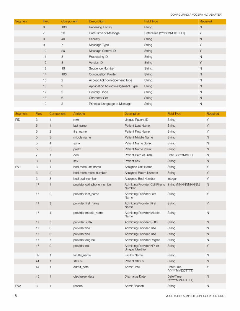
ADT (Admit/Discharge/Transfer)ADT messages are sent to Vocera Platform including the demographic, status, and location information of a patient. Vocera Platformaggregates this data and uses it to provide context to the various alerts and/or other events generated.
Segment Field Component Description Field Type Required
MSH 1 1 Field Separator String Y
2 4 Encoding Characters String Y
3 180 Sending Application String Y
4 180 Sending Facility String Y
5 180 Receiving Application String Y
CONFIGURING A VOCERA HL7 ADAPTER
18 VOCERA HL7 ADAPTER CONFIGURATION GUIDE
Segment Field Component Description Field Type Required
6 180 Receiving Facility String N
7 26 Date/Time of Message Date/Time (YYYYMMDDTTTT) Y
8 40 Security String N
9 7 Message Type String Y
10 20 Message Control ID String Y
11 3 Processing ID String N
12 8 Version ID String Y
13 15 Sequence Number String N
14 180 Continuation Pointer String N
15 2 Accept Acknowledgement Type String N
16 2 Application Acknowledgement Type String N
17 2 Country Code String N
18 6 Character Set String N
19 3 Principal Language of Message String N
Segment Field Component Attribute Description Field Type Required
PID 3 1 mrn Unique Patient ID String Y
5 1 last name Patient Last Name String Y
5 2 first name Patient First Name String Y
5 3 middle name Patient Middle Name String N
5 4 suffix Patient Name Suffix String N
5 5 prefix Patient Name Prefix String N
7 1 dob Patient Date of Birth Date (YYYYMMDD) N
8 1 sex Patient Sex String N
PV1 3 1 bed.room.unit.name Assigned Unit Name String Y
3 2 bed.room.room_number Assigned Room Number String Y
3 3 bed.bed_number Assigned Bed Number Integer Y
17 1 provider.cell_phone_number Admitting Provider Cell PhoneNumber
String (NNNNNNNNNN) N
17 2 provider.last_name Admitting Provider LastName
String Y
17 3 provider.first_name Admitting Provider FirstName
String Y
17 4 provider.middle_name Admitting Provider MiddleName
String N
17 5 provider.suffix Admitting Provider Suffix String N
17 6 provider.title Admitting Provider Title String N
17 6 provider.title Admitting Provider Title String N
17 7 provider.degree Admitting Provider Degree String N
17 9 provider.npi Admitting Provider NPI orUnique Identifier
String Y
39 1 facility_name Facility Name String N
41 1 status Patient Status String N
44 1 admit_date Admit Date Date/Time(YYYYMMDDTTTT)
Y
45 1 discharge_date Discharge Date Date/Time(YYYYMMDDTTTT)
N
PV2 3 1 reason Admit Reason String N

CONFIGURING A VOCERA HL7 ADAPTER
19 VOCERA HL7 ADAPTER CONFIGURATION GUIDE
ROL (Role)The ROL segment contains the data necessary to add, update, correct, and delete from the record persons involved, as well as theirfunctional involvement with the activity being transmitted. For Vocera Platform deployments utilizing the ROL segment, additional datasetsand rules will need to be custom-built by the Vocera Platform Implementation Engineer. Columns in the table below are incomplete becausethe segment data will be custom-built.
Note: Not included in the Vocera Platform EMDAN standard solution.
Segment Field Component Attribute Description Field Type Required
ROL 1 Role Instance ID N
2 Action Code N
3 Role-ROL Y
4 Role Person Y
5 Role Begin Date/Time N
6 Role End Date/Time N
7 Role Duration N
8 Role Action Reason N
9 Provider Type N
10 Organization Unit Type N
11 Office/Home Address/Birthplace
N
12 Phone N
ORU (Observational Result)ORU messages contain lab result information that is used to deliver critical lab result notifications. Vocera Platform only receives ORUmessages that are intended to trigger an alert to the appropriate recipient.
Segment Field Component Description Field Type Required
MSH 1 1 Field Separator String Y
2 4 Encoding Characters String Y
3 180 Sending Application String Y
4 180 Sending Facility String Y
5 180 Receiving Application String Y
6 180 Receiving Facility String N
7 26 Date/Time of Message Date/Time (YYYYMMDDTTTT) Y
8 40 Security String N
9 7 Message Type String Y
10 20 Message Control Id String Y
11 3 Processing Id String N
12 8 Version Id String Y
13 15 Sequence Number String N
14 180 Continuation Pointer String N
15 2 Accept Acknowledgement Type String N
16 2 Application Acknowledgement Type String N
17 2 Country Code String N
18 6 Character Set String N
19 3 Principal Language of Message String N

CONFIGURING A VOCERA HL7 ADAPTER
20 VOCERA HL7 ADAPTER CONFIGURATION GUIDE
Segment Field Component Attribute Description Field Type Required
PID 3 1 patient.mrn Patient ID Mapped ID Y
5 1 patient.last_name Patient Name String Y
5 2 patient.first_name Patient Name String Y
5 3 patient.middle_name Patient Name String N
5 4 patient.suffix Patient Suffix String N
5 5 patient.prefix Patient Prefix String N
7 1 patient.dob Patient Date of Birth Date (YYYYMMDD) N
8 1 patient.sex Patient Sex String N
OBR 4 1 abbreviation Test Name Abbreviation String Y
4 2 name Test Name String Y
7 1 order_time Observation Date/Time Date/Time(YYYYMMDDTTTT)
Y
16 2 provider.last_name Ordering Provider Last Name String Y
16 3 provider.first_name Ordering Provider First Name String Y
16 4 provider.middle_name Ordering Provider MiddleName
String N
16 5 provider.suffix Ordering Provider Suffix String N
16 6 provider.title Ordering Provider Title String N
16 7 provider.degree Ordering Provider Degree String N
16 9 provider.npi Ordering Provider NPI orUnique ID
String Y
17 1 provider.cell_phone_number Order Callback TelephoneNumber
String N
OBX 3 1 results.abbreviation Result Name Abbreviation String Y
3 2 results.name Result Name String Y
5 1 results.value Result Value String Y
7 1 results.range Result Reference Range String N
7 2 results.units Result Units String Y
7 4 results.note Result Notes String N
8 1 results.flag Result Flag String N
11 1 results.status Result Status String N
14 1 results.time Result Time Date/Time(YYYYMMDDTTTT)
Y
PV1 3 1 patient.bed.room.unit.name Assigned Patient Location String Y
3 2 patient.bed.room.room_number Assigned Patient Location Integer Y
3 3 patient.bed.bed_number Assigned Patient Location Integer Y
39 1 patient.facility_name Facility Name String N
41 1 patient.status Status String N
44 1 patient.admit_date Admit Date Date/Time(YYYYMMDDTTTT)
Y
45 1 patient.discharge_date Discharge Date Date/Time(YYYYMMDDTTTT)
N
ORM (Order Message, non-perfected)ORM messages include details of an Order that was placed in the health information system (HIS). ORM messages will trigger an ordernotification such as STAT or NOW and deliver the relevant information to the appropriate recipient.

CONFIGURING A VOCERA HL7 ADAPTER
21 VOCERA HL7 ADAPTER CONFIGURATION GUIDE
Segment Field Component Description Field Type Required
MSH 1 1 Field Separator String Y
2 4 Encoding Characters String Y
3 180 Sending Application String Y
4 180 Sending Facility String Y
5 180 Receiving Application String Y
6 180 Receiving Facility String N
7 26 Date/Time of Message Date/Time (YYYYMMDDTTTT) Y
8 40 Security String N
9 7 Message Type String Y
10 20 Message Control Id String Y
11 3 Processing Id String N
12 8 Version Id String Y
13 15 Sequence Number String N
14 180 Continuation Pointer String N
15 2 Accept Acknowledgement Type String N
16 2 Application Acknowledgement Type String N
17 2 Country Code String N
18 6 Character Set String N
19 3 Principal Language of Message String N
Segment Field Component Attribute Description Field Type Required
PID 3 1 patient.mrn Patient ID Mapped ID Y
5 1 patient.last_name Patient Name String Y
5 2 patient.first_name Patient Name String Y
5 3 patient.middle_name Patient Name String N
5 4 patient.suffix Patient Name String N
5 5 patient.prefix Patient Name String N
7 1 patient.dob Patient Date of Birth Date (YYYYMMDD) N
8 1 patient.sex Patient Sex String N
PV1 3 1 patient.bed.room.unit.name Assigned Patient Location String Y
3 2 patient.bed.room.room_number Assigned Patient Location Integer Y
3 3 patient.bed.bed_number Assigned Patient Location Integer Y
ORC 5 1 status Order Status String Y
9 1 order_time Ordered Time Date/Time(YYYYMMDDTTTT)
Y
OBR 4 1 order_code Order Code String Y
4 2 description Order Description String Y
16 2 provider.last_name Ordering Provider Last Name String Y
16 3 provider.first_name Ordering Provider First Name String Y
16 4 provider.middle_name Ordering Provider MiddleName
String N
16 5 provider.suffix Ordering Provider Suffix String N
16 6 provider.title Ordering Provider Title String N
16 7 provider.degree Ordering Provider Degree String N
16 9 provider.npi Ordering Provider NPI orUnique ID
String Y

CONFIGURING A VOCERA HL7 ADAPTER
22 VOCERA HL7 ADAPTER CONFIGURATION GUIDE
Segment Field Component Attribute Description Field Type Required
17 1 provider.cell_phone_number Order Callback TelephoneNumber
String N
RAS (Pharmacy/treatment Administration Message, non-perfected)RAS messages include details of an pharmacy/treatment that was placed in the health information system (HIS). RAS messages will triggeran pharmacy/treatment notification and deliver the relevant information to the appropriate recipient.
Segment Field Component Description Field Type Required
MSH 1 1 Field Separator String Y
2 4 Encoding Characters String Y
3 180 Sending Application String Y
4 180 Sending Facility String Y
5 180 Receiving Application String Y
6 180 Receiving Facility String N
7 26 Date/Time of Message Date/Time (YYYYMMDDTTTT) Y
8 40 Security String N
9 7 Message Type String Y
10 20 Message Control Id String Y
11 3 Processing Id String N
12 8 Version Id String Y
13 15 Sequence Number String N
14 180 Continuation Pointer String N
15 2 Accept Acknowledgement Type String N
16 2 Application Acknowledgement Type String N
17 2 Country Code String N
18 6 Character Set String N
19 3 Principal Language of Message String N
Segment Field Component Attribute Description Field Type Required
PID 3 1 patient.mrn Patient ID Mapped ID Y
PV1 3 1 patient.bed.room.unit.name Assigned Patient Location String Y
3 2 patient.bed.room.room_number Assigned Patient Location Integer Y
3 3 patient.bed.bed_number Assigned Patient Location Integer Y
ORC 2 1 order_code Entity Identifier String
5 1 status Order Status String Y
7 1 dosage Quantity Composite Quantity withUnits
7 2 frequency Interval Repeat Interval
7 3 description Duration String
9 1 order_time Ordered Time Date/Time(YYYYMMDDTTTT)
Y
10 1 provider.npi ID Number String
10 2 provider.last_name Provider Family Name FN (Family Name)
10 3 provider.first_name Provider Given Name String

CONFIGURING A VOCERA HL7 ADAPTER
23 VOCERA HL7 ADAPTER CONFIGURATION GUIDE
Viewing HL7 Message Logs on a Vocera Platform ApplianceSupport and implementation staff may need to search HL7 logs on a Vocera Platform appliance for troubleshooting or performance tuningefforts.
For additional Vocera Platform HL7 information, see Understanding HL7 Messaging Specifications on page 16.
The logs are present in the system as a stream of HL7 message data, such as the following. On Linux systems, the HL7 message separatoris displayed as "^M" and does not result in a visual separation, making it difficult to read the log:
MSH|^~\&|Extension||||||ADT^A08|3168|T|2.3^MPID|||9876543211234567||Smith^John|||M^MPV1|||UNIT1^01^1||||0987654^Grant^Sarah||||||||||||||||||||||||||||||||FACILITY1||ADM^MROL|1||Registered Nurse|Brown^Jane|12345678912345^MROL|2||Registered Nurse|Jones^Mary|987654321122433^MROL|3||Registered Nurse|Smith^Sally|12345678987654^MROL|4||Registered Nurse|White^James|98765432198765
In the same HL7 log shown below, bold text marks the '^M' segment separator to show where one message segment ends and the nextmessage segment begins:
MSH|^~\&|Extension||||||ADT^A08|3168|T|2.3^MPID|||9876543211234567||Smith^John|||M^MPV1|||UNIT1^01^1||||0987654^Grant^Sarah||||||||||||||||||||||||||||||||FACILITY1||ADM^MROL|1||Registered Nurse|Brown^Jane|12345678912345^MROL|2||Registered Nurse|Jones^Mary|987654321122433^MROL|3||Registered Nurse|Smith^Sally|12345678987654^MROL|4||RegisteredNurse|White^James|98765432198765
A new line can be added after the message segment separator so that each message segment appears on a separate line, making it easierto read the logs at a glance. Note that the '^M' characters display at the end of each new line in the example message. Whatever methodis used to view the logs on separate lines, Vocera Platform recommends preserving the message separation characters to maintain dataintegrity for additional troubleshooting or tuning.
MSH|^~\&|Extension||||||ADT^A08|3168|T|2.3^MPID|||9876543211234567||Smith^John|||M^MPV1|||UNIT1^01^1||||0987654^Grant^Sarah||||||||||||||||||||||||||||||||FACILITY1||ADM^MROL|1||Registered Nurse|Brown^Jane|12345678912345^MROL|2||Registered Nurse|Jones^Mary|987654321122433^MROL|3||Registered Nurse|Smith^Sally|1234567898765^MROL|4||Registered Nurse|White^James|98765432198765
Linux tr and grepThe Linux "tr" (translate) command can be used to view the logs directly in the Terminal, one message segment per line.
tr "\r" "\n" < file.txt
The tr command does not leave the ^M characters at the end of the line. However, since this command only displays the text in theTerminal window, it does not change the file and data integrity is not at risk.
Combined with grep's command-line regular expression search, the tr command can be used to find and display HL7 messages. In thisexample, "file.txt" is the file or the path to the file you want to view, and "search" is the element to search for.
tr "\r" "\n" < file.txt | grep "search"
Use the following grep commands as needed to display the desired search results:
Command Behavior
-B n Changes the number of lines you see before the line with the found elementto be n lines
-A n Changes the number of lines you see after the line with the found element tobe n lines
-C n-n Changes the number of lines you see before and after the line with the foundelement to be n lines
Unix viThe "vi" editor can be used to modify the contents of a log file. Vocera Platform recommends copying the log file and saving it to a remotelocation (such as the /tmp or home directory) before modifying the file.

CONFIGURING A VOCERA HL7 ADAPTER
24 VOCERA HL7 ADAPTER CONFIGURATION GUIDE
After making changes, it is possible to simply view the contents or to save the modified file for further investigation later. Additionally, it isrecommended to preserve a representation of the carriage return characters for the most reliable interpretation after the modification hasbeen made.
The command shown below replaces the carriage return with ^M and a new line:
:%s/<ctrl-v><ctrl-M>/^M<ctrl-v><ctrl-M>/g

25 VOCERA HL7 ADAPTER CONFIGURATION GUIDE
Understanding the Vocera HL7 Adapter Rules
An HL7 rule specifies how to generate (and send) a single message when an event occurs. An outbound connection must be specified onthe Vocera HL7 Adapter instance for the rule in order to send the message.
When the Vocera HL7 Adapter is triggered to send messages to a recipient, an HL7 rule defines the parameters used to formulate themessage. The HL7 rule is defined on a dataset, and builds an HL7 message from the dataset record (including linked records) that triggeredthe rule.
See the Vocera Platform Dataset Guide for information about working with rules. See Configuring a Vocera HL7 Adapter on page 6 forinformation about the adapter settings.
In the Adapter Settings, configure the Rule Settings fields to manage building the message.

UNDERSTANDING THE VOCERA HL7 ADAPTER RULES
26 VOCERA HL7 ADAPTER CONFIGURATION GUIDE
Message TypeClick the Build from Message Type field and select a Message Type from the dropdown list that displays. In the example below, theMessage Type of ADT is selected.
Once the Message Type is selected, the Select an event... field appears. Click on the field to display a dropdown menu, and choose fromthe events associated with the Message Type selected above. In the example below, the Event of A01 is selected.
Once the Event Type is selected, the Application Identifier field appears. This is an optional entry field, and the entry is used in the MSHsegments Field 3 (sending application) and possibly in Field 5 (receiving application). The identifier is expected to contain a GUID, or twoGUIDs separated by an underscore ('_') character. The identifier will be split at the underscore character and the second GUID will be usedas the receiving application.
If desired, select a new Message Type and Event in the Build from Message Type fields to replace this definition. Generating a newdefinition will replace the existing configuration in the Message Type field.

UNDERSTANDING THE VOCERA HL7 ADAPTER RULES
27 VOCERA HL7 ADAPTER CONFIGURATION GUIDE
Setting Description
Message Type The HL7 Message Type to send. This will be used as the message type(MSH field 9) in the outgoing message. This is a required field.
Application Identifier The value to use for the HL7 sending application (MSH field 3). If the valuecontains an '_', then the part after it will be used as the receiving application(MSH field 5).
Segment DefinitionsAt least one segment definition must be provided for a message definition. Each segment definition will cause a single segment (or more ifRepeating Link Path is configured) to be added to the message.
Note: All HL7 messages build their MSH segments with an internal segment definition. All existing MSH segment definitions areignored.
Click Add Segment Definition to create additional segments. A New Segment Definition expansion box will appear at the bottom of thesegment list. Drag and drop segment definitions to re-order the list; for example, you might select the New Segment Definition and drag itto the top of the list for configuration.
Expand an existing segment definition to edit the configuration. Links at the bottom of this field are provided to remove a segment definition,remove the last field definition, and add a field definition.
Setting Description
Name The HL7 name of the segment definition to be generated. This field isautomatically populated if the segment is generated from the Message Typeselection options. This is a required field.
Repeating Link Path This optional field specifies a link path relative to the triggering object anddetermines the number of instances of the segment to generate, basedon the number of linked objects found at that path. One instance of thesegment will be generated for each object found using the path.
Field DefinitionsAt least one field definition must be configured for a segment definition. Each field definition defines the content of the corresponding field inthe segment.
Expand an existing field definition to edit the configuration. Configure a field definition as described in the table below. In this example, theROL segment definition will use the role.name attribute path in the message content to send.

UNDERSTANDING THE VOCERA HL7 ADAPTER RULES
28 VOCERA HL7 ADAPTER CONFIGURATION GUIDE
Setting Description
Content Type Indicates how the information specified in the Content field will be usedwhen generating the field for the message. Content Type options areAttribute Paths, Text, Sequence Number (described below). This is arequired field.
Attribute Paths: Indicates that the field content is treated as a set of attributepaths rooted in the triggering object. Constant text can be placed in single ordouble quotes. HL7 separators should not use quotation marks. This optionis recommended over the Text option unless the field contains fixed text.
Text: Indicates that the field content contains the exact text to be placed inthe field. Any HL7 separators will be included without quotation marks.
Sequence Number: Indicates the field will contain a sequentially generatedsegment identifier. This option should be used when the Repeating LinkPath value is set for the segment and the field is defined to be a "Set ID". Ifpresent, the field content will contain the first value to use (default value is 1).
Content The content to be sent for the message; the interpretation of this contentdepends on the Content Type value selected above. Use the default HL7separators; ^ for components and & for subcomponents.
List of Messaging SpecificationsADT, ORM, ORU message details are published in the Understanding HL7 Messaging Specifications on page 16. This page describeseach message type by segment, field, component, description, field type, and its required status.

29 VOCERA HL7 ADAPTER CONFIGURATION GUIDE
Understanding Adapter Installation
Adapters are installed on the Vocera Platform in a solution package, or individually as needed by the customer.
The Vocera Platform uses adapters to integrate with external systems and devices. Each adapter is configured by the user to includeinformation that will allow the Vocera Platform to communicate and interact with a specific type of resource and, depending on the adapter,devices that resource may control. Adapters can allow the Vocera Platform to monitor and collect data, as well as send data out, whentriggered manually or automatically.
When implementing Vocera Platform at a customer site, use this document to install an adapter that is not supplied in the Gold Image.Otherwise, you will install a needed adapter when instructed in the solution package installation process described in the Vocera PlatformInstallation Guide.
Accessing Supported AdaptersSupported adapters that are not included in the solution Gold Image can be installed at a customer site.
Many Vocera Platform adapters are provided in the solution's Gold Image for installation during the customer implementation. Supportedadapters that are not included in the solution Gold Image can be installed at a customer site using the instructions provided in the Installingan Adapter on page 31 document.
The following two tables describe the set of adapters in Vocera Platform versions 5.5 and 6.0. The first table lists the adapters provided inthe Gold Image. The second table lists the optional adapters available for installation.
Adapters provided in the Gold Image
Adapter Name Platform 5.5 Platform 6.0
ascom-interface extension-ascom-interface-1.7.118-0.x86_64.rpm extension-ascom-interface-1.8.0.1.x86_64.rpm
compliancelogger-interface extension-compliance-logger-interface-1.0.103-0.x86_64.rpm
extension-compliance-logger-interface-1.1.0.7.x86_64.rpm
cucm-interface extension-cucm-interface-2.5.0-0.x86_64.rpm extension-cucm-interface-2.6.0.2.x86_64.rpm
data-export-interface extension-data-export-interface-1.4.1-0.x86_64.rpm
extension-data-export-interface-1.5.0.3.x86_64.rpm
hill-rom-clinical-interface extension-hill-rom-clinical-interface-2.0.8-0.x86_64.rpm
extension-hill-rom-clinical-interface-2.1.0.2.x86_64.rpm
hl7-interface extension-hl7-interface-1.4.5-0.x86_64.rpm extension-hl7-interface-1.5.0.2.x86_64.rpm
incoming-email-interface extension-incoming-email-interface-1.15.101-0.x86_64.rpm
extension-incoming-email-interface-1.16.0.1.x86_64.rpm
ldap-interface extension-ldap-interface-1.3.0-0.x86_64.rpm extension-ldap-interface-2.0.0.13.x86_64.rpm
media-interface extension-media-interface-1.0.105-0.x86_64.rpm extension-media-interface-1.1.0.1.x86_64.rpm
outgoing-email-interface extension-outgoing-email-interface-1.6.102-0.x86_64.rpm
extension-outgoing-email-interface-1.7.0.2.x86_64.rpm
responder-sync-interface extension-responder-sync-interface-4.0.6-0.x86_64.rpm
extension-responder-sync-interface-5.0.0.34.x86_64.rpm
spacelabs-cei-interface extension-spacelabs-cei-interface-1.0.109-0.x86_64.rpm
extension-spacelabs-cei-interface-1.1.0.5.x86_64.rpm

UNDERSTANDING ADAPTER INSTALLATION
30 VOCERA HL7 ADAPTER CONFIGURATION GUIDE
Adapter Name Platform 5.5 Platform 6.0
spectralink-interface extension-spectralink-interface-2.1.103-0.x86_64.rpm
extension-spectralink-interface-2.2.0.2.x86_64.rpm
tap-interface extension-tap-interface-1.10.2-0.x86_64.rpm extension-tap-interface-1.11.0.5.x86_64.rpm
vocera-interface extension-vocera-interface-3.1.0-1.x86_64.rpm Not supported
xmpp-interface extension-xmpp-interface-3.4.2-0.x86_64.rpm extension-xmpp-interface-4.0.0.328.x86_64.rpm
Optional Adapters
Adapter Name Platform 5.5 Platform 6.0
amion-interface extension-amion-interface-1.0.0-0.x86_64.rpm extension-amion-interface-1.0.0-0.x86_64.rpm
assignmentgroupsync-interface extension-assignment-group-sync-service-1.0.1-0.x86_64.rpm
extension-assignment-group-sync-service-2.0.0.4.x86_64.rpm
assignmentmanager-interface extension-assignment-manager-interface-1.1.2-0.x86_64.rpm
extension-assignment-manager-interface-2.0.0.4.x86_64.rpm
carescape-interface extension-carescape-interface-1.1.108-0.x86_64.rpm
extension-carescape-interface-1.2.0.1.x86_64.rpm
earlysense-interface extension-earlysense-interface-1.0.102-0.x86_64.rpm
extension-earlysense-interface-1.1.0.2.x86_64.rpm
incomingvmi-interface extension-incoming-vmi-interface-1.0.0-1.x86_64.rpm
extension-incoming-vmi-interface-1.1.0.4.x86_64.rpm
incomingwctp-interface extension-incoming-wctp-interface-1.0.0-1.x86_64.rpm
extension-incoming-wctp-interface-1.0.0.31.x86_64.rpm
navicare-interface extension-navicare-interface-1.4.2-0.x86_64.rpm extension-navicare-interface-1.5.0.2.x86_64.rpm
nihon-kohden-interface extension-nihon-kohden-interface-1.1.102-0.x86_64.rpm
extension-nihon-kohden-interface-1.2.0.2.x86_64.rpm
outgoing-wctp-interface extension-outgoing-wctp-interface-2.0.0-2.x86_64.rpm
extension-outgoing-wctp-interface-2.0.0-2.x86_64.rpm
patient_context-service extension-patient-context-service-1.0.0-0.x86_64.rpm
Not supported
qgenda-interface extension-qgenda-interface-1.0.0-2.x86_64.rpm
sip-interface extension-sip-interface-1.4.0-0.x86_64.rpm extension-sip-interface-1.4.0-0.x86_64.rpm
soap-publisher-interface extension-soap-publisher-interface-1.0.112-0.x86_64.rpm
extension-soap-publisher-interface-1.1.0.2.x86_64.rpm
soap-subscriber-interface extension-soap-subscriber-interface-1.0.113-0.x86_64.rpm
extension-soap-subscriber-interface-1.1.0.2.x86_64.rpm
sotera-esii-interface extension-sotera-esii-interface-1.0.113-0.x86_64.rpm
extension-sotera-esii-interface-1.1.0.2.x86_64.rpm
stryker-interface extension-stryker-interface-1.0.102-0.x86_64.rpm extension-stryker-interface-1.1.0.3.x86_64.rpm
vmp-interface extension-vmp-interface-1.1.0-0.x86_64.rpm Not supported
voice-group-sync-interface extension-voice-group-sync-interface-1.0.3.12.x86_64.rpm
Not supported
Recreating a RepositoryIn the event that the repository reference file has been compromised, you can re-create the platform repository.
This information should be specified on the related adapter's Release Information page in the wiki. See Releases and navigate to theneeded adapter.
1. Verify that the adapter resides in a repository which is in '/etc/yum.repos.d/'.
2. If the repolist or yum commands fail, verify that the file exists and try again. For example, use the following code to verify the repositoryexists on the Vocera Platform appliance:
[tpx-admin@engage log]$ cat /etc/yum.repos.d/vocera.repo

UNDERSTANDING ADAPTER INSTALLATION
31 VOCERA HL7 ADAPTER CONFIGURATION GUIDE
3. Verify the output appears as shown.
#---------------------------------------------------------------------------------------------# NOTICE: Only use the General Availability (platform-6.X-ga) repository for customer deployments.# Use of Controlled Release (platform-6.X-cr) or Software Quality Assurance (platform-6.X-sqa) in# accordance to process QOP-75-01 Production Work Order and History Record, contact your# manager for questions. #---------------------------------------------------------------------------------------------[Platform-6.0]name=Platform-6.0baseurl=https://box.voceracommunications.com/Platform-6.0-GAenabled=1gpgcheck=0
Installing an AdapterInstall or uninstall a Vocera Platform adapter at a customer site on a Vocera system for a customer.
Execute the following steps using the system's command prompt.
1. Verify that the adapter resides in a repository which is in '/etc/yum.repos.d/'.
2. Run the following commands:
sudo yum clean allsudo yum check-updates
3. Verify that the rpm package to be installed is available using the following command:
sudo yum list available | grep extension4. Install the adapter by specifying its rpm package name in place of <package-name> in the code below. (This information should be
specified on the related Release Information page in the wiki; see Release Notes.)
sudo yum install <package-name>5. Uninstall an adapter by specifying its rpm package name in place of <package-name> in the code below. (This information should be
specified on the related Release Notes page; see Release Notes.)
sudo yum remove <package name>
Practicing an Adapter InstallationReplicate these steps using the needed adapter package, in order to install adapters other than the example given here.
1. Verify the repo file contains the repos up to and including the release of interest.
[tpx-admin@engage log]$ cat /etc/yum.repos.d/vocera.repo#---------------------------------------------------------------------------------------------# NOTICE: Only use the General Availability (platform-6.X-ga) repository for customer deployments.# Use of Controlled Release (platform-6.X-cr) or Software Quality Assurance (platform-6.X-sqa) in# accordance to process QOP-75-01 Production Work Order and History Record, contact your# manager for questions. #---------------------------------------------------------------------------------------------[Platform-6.0]name=Platform-6.0baseurl=https://box.voceracommunications.com/Platform-6.0-GAenabled=1gpgcheck=0
2. Execute the following commands:
[tpx-admin@engage log] $ sudo yum check-updatesLoaded plugins: langpacks, product-id, subscription-managerThis system is not registered to Red Hat Subscription Management. You can use subscription-manager to register. Quartz | 3.6 kB 00:00:00 (1/2): Quartz/group_gz | 483 B 00:00:00 (2/2): Quartz/primary_db | 29 kB 00:00:00
3. Verify the package is available, using the following command:
[tpx-admin@engage log] $ sudo yum list available | grep extension

UNDERSTANDING ADAPTER INSTALLATION
32 VOCERA HL7 ADAPTER CONFIGURATION GUIDE
extension-navicare-interface.x86_64 1.3.6-0 Platform 5.04. Install the needed adapter; in this example, install the Navicare adapter:
[tpx-admin@engage log] $ sudo yum install extension-navicare-interfaceLoaded plugins: langpacks, product-id, subscription-managerThis system is not registered to Red Hat Subscription Management. You can use subscription-manager to register.Resolving Dependencies--> Running transaction check---> Package extension-navicare-interface.x86_64 0:1.3.6-0 will be installed--> Finished Dependency Resolution
Dependencies Resolved
============================================================================================================================================================ Package Arch Version Repository Size============================================================================================================================================================Installing: extension-navicare-interface x86_64 1.3.3-0 Quartz 59 k
Transaction Summary============================================================================================================================================================Install 1 Package
Total download size: 59 kInstalled size: 62 kIs this ok [y/d/N]: yDownloading packages:extension-navicare-interface-1.3.6-0.x86_64.rpm | 59 kB 00:00:00 Running transaction checkRunning transaction testTransaction test succeededRunning transaction Installing : extension-navicare-interface-1.3.6-0.x86_64 1/1 Verifying : extension-navicare-interface-1.3.6-0.x86_64 1/1
Installed: extension-navicare-interface.x86_64 0:1.3.6-0
Complete!5. This completes the steps to install an adapter.

33 VOCERA HL7 ADAPTER CONFIGURATION GUIDE
Navigating the Vocera Platform Adapters
Access the Adapters tab and use the filter or search tools to display a specific adapter.
This page is used by all the adapter guides, and therefore, the adapter used as an example here may not be the adapter that you areworking with currently.
1. Access the Vocera Platform Web Console and sign in with your system credentials.
2. Select Settings > Adapters in the navigation menu.
The Adapters page displays.
3. Select an adapter to work with from the list displayed in the grid, or select the New Adapter Action option to create a new adapter.
On the Adapters page you can identify adapters by their name or component name. The Enabled column (displaying a true or falsestatus) indicates whether the adapter is active on the system, or disabled.
The bottom row of the grid reports the number of adapters displayed, of the available adapters.
The Filter Disabled box is checked by default, and displays only the enabled adapters that are configured on the Vocera Platform.

NAVIGATING THE VOCERA PLATFORM ADAPTERS
34 VOCERA HL7 ADAPTER CONFIGURATION GUIDE
4. Uncheck the Filter Disabled box to display all the adapters that have been installed, including those that are not currently enabled. Thecolumn title now displays All Adapters.
The Filter Disabled box is checked by default.
5. Enter a term in the Search field to locate a needed adapter on the system.
The search field is identified by a text field with a magnifying glass icon. The search is performed on the Name and Component Namecolumns.
When results are returned, the column header displays Adapters Search Results and an x icon allows you to clear the search field.

NAVIGATING THE VOCERA PLATFORM ADAPTERS
35 VOCERA HL7 ADAPTER CONFIGURATION GUIDE
Editing an AdapterEdit an adapter that has been installed on the Vocera Platform.
This page is used by all the adapter guides, and therefore, the adapter used as an example here may not be the adapter that you areworking with currently.
1. Access the Vocera Platform Web Console and navigate to the adapters.
See Navigating the Vocera Platform Adapters on page 33 for instructions.
2. Select the adapter to edit in the Adapters list.
3. Select Edit in the adapter's menu.
The Update Adapter page for the adapter displays.
4. Edit the adapter's settings to revise the configuration as needed. See the adapter-specific configuration page for details on working withsettings for this adapter.
Select an empty field and begin typing, or select an existing value and type over it. To keep an existing value, do not edit that field.
5. Select one of the options to exit the Update Adapter page. See Saving an Adapter on page 37 for details.
Creating a New AdapterAccess the Vocera Platform Web Console to work with adapters, or create a new adapter when prompted in the package import process.
This page is used by all the adapter guides, and therefore, the adapter used as an example here may not be the adapter that you areworking with currently.

NAVIGATING THE VOCERA PLATFORM ADAPTERS
36 VOCERA HL7 ADAPTER CONFIGURATION GUIDE
1. Access the Vocera Platform Web Console and navigate to the adapters.
See Navigating the Vocera Platform Adapters on page 33 for instructions.
2. Select New Adapter in the Action menu on the Adapters page.
The Create a New Adapter dialog displays.
3. Complete the configuration fields.
Name Description
Component Name * Select the Component Name field dropdown arrow to display a list of the systems and devices that Voceracurrently supports. Select the name of the adapter to create.
Reference Name Enter a short descriptive name in the Reference Name field to uniquely identify an adapter instance. It maydemonstrate the adapter function or other information; for example, Production adapter may differentiate a liveadapter from a development or "sandbox" adapter.
Enabled Select the Enabled check box to allow Vocera Platform to use the new adapter. Vocera ignores the adapter ifthis option is disabled.
4. Select Upload Bundle in the Action menu to install a package on a Vocera Platform.
Use the Upload Bundle feature to install when the adapter is not available in the Component Name dropdown list, and you havedownloaded the needed adapter bundle to a storage location.
5. Click on Browse to navigate to the bundle to install.

NAVIGATING THE VOCERA PLATFORM ADAPTERS
37 VOCERA HL7 ADAPTER CONFIGURATION GUIDE
6. Select one of the Action options to exit from the Upload a Bundle dialog.
• Upload: Upload the selected bundle to the appliance.
• Cancel: Close the Upload a Bundle dialog without making a change to the system.
Saving an AdapterClose an adapter configuration dialog using the Save, Reset, or Cancel options.
This page is used by all the adapter guides, and therefore, the adapter used as an example here may not be the adapter that you areworking with currently.
When creating a new adapter, the options at the bottom of the adapter configuration page are Save, and Cancel.
When editing an existing adapter, the options are Save, Reset, and Cancel.
Choose an option to close the dialog:
Option Description
Save Select Save to store the adapter configuration in the system, when the fieldsare set to desired specifications.
Cancel Select Cancel to close the configuration window without saving yourchanges to the system.
Reset Select Reset to clear all fields without closing the window, in order to selectother specifications for the adapter's settings.
Deactivating an AdapterTemporarily deactivate an adapter to avoid unintentional use of it in an implementation.
This page is used by all the adapter guides, and therefore, the adapter used as an example here may not be the adapter that you areworking with currently.
1. Access the Vocera Platform Web Console and navigate to the adapter to deactivate.
See Navigating the Vocera Platform Adapters on page 33 for instructions.
NAVIGATING THE VOCERA PLATFORM ADAPTERS
38 VOCERA HL7 ADAPTER CONFIGURATION GUIDE
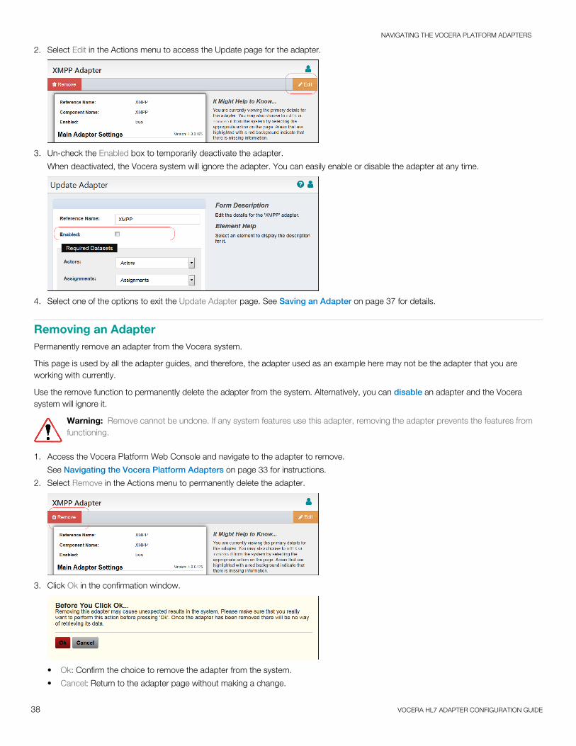
2. Select Edit in the Actions menu to access the Update page for the adapter.
3. Un-check the Enabled box to temporarily deactivate the adapter.
When deactivated, the Vocera system will ignore the adapter. You can easily enable or disable the adapter at any time.
4. Select one of the options to exit the Update Adapter page. See Saving an Adapter on page 37 for details.
Removing an AdapterPermanently remove an adapter from the Vocera system.
This page is used by all the adapter guides, and therefore, the adapter used as an example here may not be the adapter that you areworking with currently.
Use the remove function to permanently delete the adapter from the system. Alternatively, you can disable an adapter and the Vocerasystem will ignore it.
Warning: Remove cannot be undone. If any system features use this adapter, removing the adapter prevents the features fromfunctioning.
1. Access the Vocera Platform Web Console and navigate to the adapter to remove.
See Navigating the Vocera Platform Adapters on page 33 for instructions.
2. Select Remove in the Actions menu to permanently delete the adapter.
3. Click Ok in the confirmation window.
• Ok: Confirm the choice to remove the adapter from the system.
• Cancel: Return to the adapter page without making a change.

NAVIGATING THE VOCERA PLATFORM ADAPTERS
39 VOCERA HL7 ADAPTER CONFIGURATION GUIDE
4. Confirm that the adapter no longer displays in the Adapters list view, when a success message displays.