voice over wlan vocera implementation - cisco.com · packet delivery † authentication ... the...
TRANSCRIPT
OL-14684-01
C H A P T E R11
Voice over WLAN Vocera ImplementationVocera OverviewThe Vocera Communications System enables wireless voice communication that users control with naturally spoken commands. The system is primarily targeted at hospitals, hotels, retail stores, and other in-building environments where mobile workers must stay in contact to perform their jobs. The Vocera Communications System consists of two key components:
• Vocera System Software—Controls and manages call activity
• Vocera Communications Badge—A lightweight, wearable, voice-controlled communication device that operates over a wireless LAN (IEEE 802.11b/g)
The Vocera Badge is briefly discussed in this chapter with minimum configurations required to integrate it with Cisco Unified Communications Manager.
The Vocera User Guide, Configuration Guide, and Infrastructure Planning Guide can be found at http://www.vocera.com/documentation/default.aspx
Note The first Badge release by Vocera is the B1000A and is the subject of this design guide. Vocera has since announced the Vocera Communications Badge B2000 with an improved wireless radio which will support WiFi Multimedia (WMM). This announcement occurred as this design guide was in the process of being released so no testing has been done on the new B2000 Badge.
Vocera System Software The Vocera System Software platform runs on a standard Windows server and contains the system intelligence, including managing calls call connections, and user profiles, as well as the Nuance speech recognition and voice-print verification software. The Administrative Console allows system administrators to set global preferences and permissions for users. User preferences are configured on the server via browser-based Administration and User Consoles.
The Vocera versions used for this design guide are as follows:
• Vocera Server 4.0 [Build 1279]
• Vocera Telephony Server 4.0 [Build 1279]
• Vocera Badge V4.0 1273
11-1Voice over Wireless LAN 4.1 Design Guide

Chapter 11 Voice over WLAN Vocera Implementation Vocera Architecture
Vocera Communications Badge The Vocera Communications Badge is a small, lightweight, wearable, wireless device that provides a voice-controlled user interface to the Vocera Communications System. The Vocera Communications Badge enables instant, hands-free conversations among people throughout the workplace. It contains a speaker, microphone, wireless radio, and a backlit LCD that shows caller ID, text messages and alerts. A Vocera Communications Badge is shown in Figure 11-1.
Figure 11-1 Vocera Communications Badge
Vocera ArchitectureThis section addresses the following Vocera architecture topics:
• Main Components, page 11-2
• Badge Overview, page 11-3
• Badge-to-Badge Communication, page 11-4
• Badge Telephony Communication, page 11-4
• Vocera Broadcast, page 11-5
• Badge Location Function, page 11-6
Main Components Primary Vocera system components consist of the following elements:
• Vocera Server Program—Provides the central system functionality, and calls on the other components for specific services.
• Embedded MySQL Database—Stores user profiles (which contain personal information and Badge settings), group and location information, and system settings.
• NuanceTM Speech Recognition, Verifier, and Vocalizer Software—Provides the speech recognition, voiceprint authentication, and text-to-speech engines used by the Vocera voice interface.
11-2Voice over Wireless LAN 4.1 Design Guide
OL-14684-01

Chapter 11 Voice over WLAN Vocera Implementation Vocera Architecture
• Apache/Tomcat Web Serve—Hosts the browser-based Administration Console and User Console applications.
Software Utilities
The Vocera system software includes the following utilities:
• Badge Properties Editor—Allows setting values for Badge properties so the Vocera Badges can connect to the wireless network.
• Badge Configuration Utility—Downloads the properties set with the Badge Properties Editor, as well as any firmware upgrades, to the Badges.
• Vconfig Utility—Provides interactive setting of individual properties and to download individual firmware components to a Badge.
The Vocera system can be a standalone communications system with Badge-to-Badge communication only. Typically the system is installed in conjunction with a PBX to allow hardphone (wired)-to-Vocera Badge communications, as well as access through the PBX to the Public Switched Telephone Network (PSTN). For this communication to take place, an Intel Dialogic board must be installed in the Vocera System Server. For this design guide an Intel Dialogic D/480JCT-1T1 (North America, T1/PRI) was used. For a list of other supported analog and digital integrations refer to the Vocera Datasheet.
A high level diagram is shown in Figure 11-2.
Figure 11-2 Vocera Architecture Diagram
Badge Overview The Badges are centrally maintained by the Vocera Server from a single configuration file for all Badges. The Badge does not have a keyboard, so this single configuration file is uploaded to all Badges. The Badge does not maintain a static DN or ID (as a typical phone would have). Instead, each Badge defines its identity when a user logs in. As a necessary consequence of this centralized management, all Badge properties, including the SSID and security settings that allow it to connect to the network, must be the same. In turn, all APs to which the Vocera Badge can connect must also share the same SSID and security settings.
ISDN PRI
VoceraServer
VoiceGateway
Cisco UnifiedCommunications
Manager
M
LWAPPSi
IPV
LWAPP
2229
63
11-3Voice over Wireless LAN 4.1 Design Guide
OL-14684-01
Chapter 11 Voice over WLAN Vocera Implementation Vocera Architecture
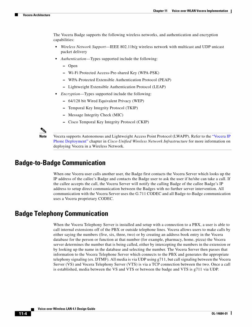
The Vocera Badge supports the following wireless networks, and authentication and encryption capabilities:
• Wireless Network Support—IEEE 802.11b/g wireless network with multicast and UDP unicast packet delivery
• Authentication—Types supported include the following:
– Open
– Wi-Fi Protected Access-Pre-shared Key (WPA-PSK)
– WPA-Protected Extensible Authentication Protocol (PEAP)
– Lightweight Extensible Authentication Protocol (LEAP)
• Encryption—Types supported include the following:
– 64/128 bit Wired Equivalent Privacy (WEP)
– Temporal Key Integrity Protocol (TKIP)
– Message Integrity Check (MIC)
– Cisco Temporal Key Integrity Protocol (CKIP)
Note Vocera supports Autonomous and Lightweight Access Point Protocol (LWAPP). Refer to the “Vocera IP Phone Deployment” chapter in Cisco Unified Wireless Network Infrastructure for more information on deploying Vocera in a Wireless Network.
Badge-to-Badge Communication When one Vocera user calls another user, the Badge first contacts the Vocera Server which looks up the IP address of the callee’s Badge and contacts the Badge user to ask the user if he/she can take a call. If the callee accepts the call, the Vocera Server will notify the calling Badge of the callee Badge’s IP address to setup direct communication between the Badges with no further server intervention. All communication with the Vocera Server uses the G.711 CODEC and all Badge-to-Badge communication uses a Vocera proprietary CODEC.
Badge Telephony Communication When the Vocera Telephony Server is installed and setup with a connection to a PBX, a user is able to call internal extensions off of the PBX or outside telephone lines. Vocera allows users to make calls by either saying the numbers (five, six, three, two) or by creating an address book entry in the Vocera database for the person or function at that number (for example, pharmacy, home, pizza) the Vocera server determines the number that is being called, either by intercepting the numbers in the extension or by looking up the name in the database and selecting the number. The Vocera Server then passes that information to the Vocera Telephone Server which connects to the PBX and generates the appropriate telephony signaling (ex. DTMF). All media is via UDP using g711, but call signaling between the Vocera Server (VS) and Vocera Telephony Server (VTS) is via a TCP connection between the two. Once a call is established, media between the VS and VTS or between the badge and VTS is g711 via UDP.
11-4Voice over Wireless LAN 4.1 Design Guide
OL-14684-01

Chapter 11 Voice over WLAN Vocera Implementation Vocera Architecture
Vocera Broadcast A Vocera Badge user can call and communicate to a group of Vocera Badges at the same time by using the broadcast command. When a user broadcasts to a group, the users Badge sends the command to the Vocera Server who looks up the members of a group, determines which members of the group are active, assigns a multicast address to use for this broadcast session, and sends a message to each active user’s Badge instructing it to join the multicast group with the assigned multicast address. More information on Vocera Multicast in an LWAPP environment can be found at “Vocera IP Phone Deployment” chapter in Cisco Unified Wireless Network Infrastructure.
Filtering a trace on IGMP Protocol allows you to see the Membership Report of a device joining the multicast group. Figure 11-3 illustrates the Badge with an IP Address of 10.33.65.202 joins Multicast Group 230.230.0.13 (hex e6 e6 00 0d).
Figure 11-3 Vocera Badge Joining Multicast Group
11-5Voice over Wireless LAN 4.1 Design Guide
OL-14684-01

Chapter 11 Voice over WLAN Vocera Implementation Vocera Architecture
After locating the Membership Report of a specific Badge joining the multicast group, look earlier in the trace for the occurrence of the Vocera Server as the source and the Badge in question as the destination. See Figure 11-4. In this example the Badge is 10.33.65.202 and the Vocera Server is 10.33.32.251. In the data you will see the occurrence of e6 e6 00 0d (hex representation of the multicast address 230.230.0.13).
Figure 11-4 Vocera Server Sending Multicast Address to Vocera Badge
Badge Location FunctionThe Vocera Server keeps track of the AP to which each active Badge is associated as each Badge will send a 30 second keepalive to the server with the associated BSSID. This allows the Vocera system to roughly estimate the location of a Badge user. This function has a relatively low degree of accuracy because a Badge might not be associated to the AP to which it is closest. A more accurate solution for finding the location of a device is the Cisco Location-Based Services (LBS).
11-6Voice over Wireless LAN 4.1 Design Guide
OL-14684-01
Chapter 11 Voice over WLAN Vocera Implementation WLAN Controller Base Configuration
WLAN Controller Base ConfigurationThis section addresses creating a Voice WLAN.
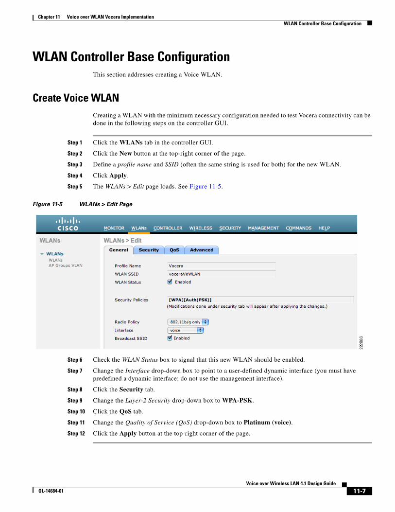
Create Voice WLAN Creating a WLAN with the minimum necessary configuration needed to test Vocera connectivity can be done in the following steps on the controller GUI.
Step 1 Click the WLANs tab in the controller GUI.
Step 2 Click the New button at the top-right corner of the page.
Step 3 Define a profile name and SSID (often the same string is used for both) for the new WLAN.
Step 4 Click Apply.
Step 5 The WLANs > Edit page loads. See Figure 11-5.
Figure 11-5 WLANs > Edit Page
Step 6 Check the WLAN Status box to signal that this new WLAN should be enabled.
Step 7 Change the Interface drop-down box to point to a user-defined dynamic interface (you must have predefined a dynamic interface; do not use the management interface).
Step 8 Click the Security tab.
Step 9 Change the Layer-2 Security drop-down box to WPA-PSK.
Step 10 Click the QoS tab.
Step 11 Change the Quality of Service (QoS) drop-down box to Platinum (voice).
Step 12 Click the Apply button at the top-right corner of the page.
11-7Voice over Wireless LAN 4.1 Design Guide
OL-14684-01

Chapter 11 Voice over WLAN Vocera Implementation Vocera Configuration
When the base controller WLAN configuration is complete, the WLAN page should look similar to the page shown in Figure 11-6.
Figure 11-6 WLANs Page with Vocera VoWLAN
Vocera ConfigurationThis section addresses Vocera Server and Vocera Badge configuration.
Server and Badge Configuration Since the Vocera Badge has no keyboard for the entry of network settings, the computer running the Vocera Badge Configuration Utility must have specific TCP/IP properties defined. This computer must also be connected to an Isolated Access Point with a specific SSID.
Refer to the Vocera Configuration Guide for information on specific TCP/IP and SSID properties required for the Isolated Access Point.
Vocera Telephony Integration
The hardware required to integrate Vocera with a PBX differs according to whether you perform an analog or a digital integration. A digital integration with Cisco Unified Communications Manager is suggested as it provides a higher density of channels than an analog integration. Specific Intel Dialogic boards are supported by Vocera and can be found in the Vocera Configuration Guide.
For this design guide the Intel® Dialogic® D/480JCT-2T1 was used with a switch protocol of NI2. Figure 11-7 and Figure 11-8 show the Dialogic settings from the Vocera Intel® Dialogic® Configuration Manager located on the Vocera Server.
11-8Voice over Wireless LAN 4.1 Design Guide
OL-14684-01

Chapter 11 Voice over WLAN Vocera Implementation Vocera Configuration
Figure 11-7 Vocera Intel® Dialogic® Configuration Manager Screen 1
11-9Voice over Wireless LAN 4.1 Design Guide
OL-14684-01

Chapter 11 Voice over WLAN Vocera Implementation Cisco Unified Communications Manager Configuration
Figure 11-8 Vocera Intel® Dialogic® Configuration Manager Screen 2
DHCP
Vocera does not allow the running of the DHCP server on the Vocera Server computer. Although the DHCP server does not typically require significant system resources, running it on the Vocera Server computer causes significant problems in a clustered environment, including the following:
• Devices may inadvertently receive duplicate IP addresses.
• Badges may not receive an IP address and get stuck displaying Requesting IP Address.
• Badges may get invalid and unusable IP address information.
Unlike Cisco IP phones, the DHCP scope does not require option 150 to be set. Option 150 defines the address of the Cisco Unified Communications Manager TFTP Server for Cisco IP phones (Vocera Badges do not communicate directly with Cisco Unified Communications Manager). If DHCP is not used, the Badges will require manual entry of network properties. Since the Badges do not have a keyboard this process is slow and error prone, thus DHCP is highly recommended.
Cisco Unified Communications Manager Configuration Communication between Cisco Unified Communications Manager and Vocera is accomplished in the same manner as connecting CUCM with a PBX. It is always suggested to use the highest level of integration that both systems can support. For example, if both systems support QSig then this would offer a more robust integration than ISDN or analog integration. In the case of Vocera they only support ISDN or analog integration so ISDN should be used whenever possible.
11-10Voice over Wireless LAN 4.1 Design Guide
OL-14684-01
Chapter 11 Voice over WLAN Vocera Implementation Cisco Unified Communications Manager Configuration
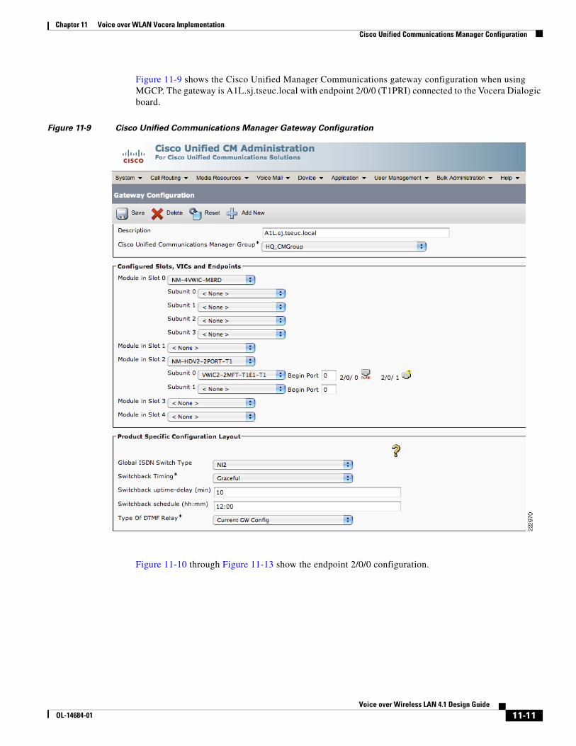
Figure 11-9 shows the Cisco Unified Manager Communications gateway configuration when using MGCP. The gateway is A1L.sj.tseuc.local with endpoint 2/0/0 (T1PRI) connected to the Vocera Dialogic board.
Figure 11-9 Cisco Unified Communications Manager Gateway Configuration
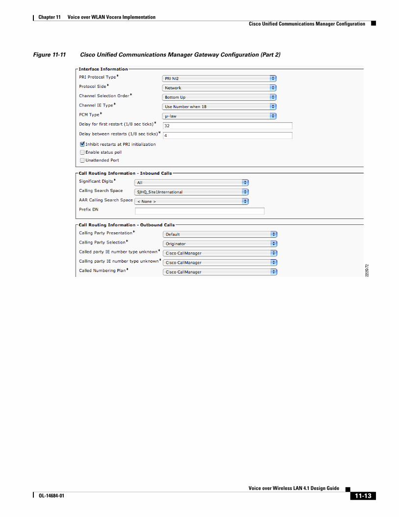
Figure 11-10 through Figure 11-13 show the endpoint 2/0/0 configuration.
11-11Voice over Wireless LAN 4.1 Design Guide
OL-14684-01

Chapter 11 Voice over WLAN Vocera Implementation Cisco Unified Communications Manager Configuration
Figure 11-10 Cisco Unified Communications Manager Gateway Configuration (Part 1)
11-12Voice over Wireless LAN 4.1 Design Guide
OL-14684-01
Chapter 11 Voice over WLAN Vocera Implementation Cisco Unified Communications Manager Configuration
Figure 11-11 Cisco Unified Communications Manager Gateway Configuration (Part 2)
11-13Voice over Wireless LAN 4.1 Design Guide
OL-14684-01

Chapter 11 Voice over WLAN Vocera Implementation Cisco Unified Communications Manager Configuration
Figure 11-12 Cisco Unified Communications Manager Gateway Configuration (Part 3)
Figure 11-13 Cisco Unified Communications Manager Gateway Configuration (Part 4)
Dial Plan and Translation
Vocera Badges are usually deployed for special-purpose areas such as on hospital or retail sales floors. It is suggested that access to the Vocera Badges be restricted by putting the Badges in their own partition that only allows those devices with a need to contact a Vocera Badge the ability to do so. The Route Pattern Configuration shown in Figure 11-14 allows all numbers within the range of 1440 to 1449 to be routed to the Vocera Server and assigns the Vocera partition.
11-14Voice over Wireless LAN 4.1 Design Guide
OL-14684-01

Chapter 11 Voice over WLAN Vocera Implementation Vocera Security
Figure 11-14 Route Pattern Configuration
Vocera Security Table 11-1 summarizes the security features supported by Vocera.
The LEAP and PEAP protocols typically require each user in a network environment to be authenticated with a unique set of credentials. However, each Badge must have the same security properties so the Vocera Server can automatically update all Badges when necessary. Consequently, Vocera supports device authentication for PEAP and LEAP, not user authentication. All Badges must present the same set of credentials for network authentication.
Table 11-1 Vocera-supported Security Features
Authentication Encryption Message Integrity Check
Open None, WEP64,WEP128 N/A
LEAP TKIP-Cisco, WEP64, WEP128 N/A
WPA-PEAP (MS-CHAP v2) TKIP-WPA MIC
WPA-PSK TKIP-WPA MIC
11-15Voice over Wireless LAN 4.1 Design Guide
OL-14684-01

Chapter 11 Voice over WLAN Vocera Implementation Vocera Radio Frequency Considerations
Applications such as voice running on client devices require fast reassociation when they roam to a different AP to prevent delays and gaps in conversation. Vocera Badges do not support fast, secure roaming so in order to provide fast roaming and a reasonable level of authentication security and encryption, WPA-PSK with TKIP should be used with the Vocera Badge (pre-B2000).
Setting the authentication and encryption is set in the WLC WLAN Layer 2 Security tab. Figure 11-15 shows the authentication and encryption setting for the Vocera WLAN.
Figure 11-15 WLAN Security Settings
Vocera Radio Frequency ConsiderationsWireless IP telephony networks require careful RF planning. A thorough voice site survey is often required to determine the proper levels of wireless coverage and to identify sources of interference. AP placement and antenna selection choices can be greatly eased with the help of the results of a valid voice site survey. For further information on Vocera RF considerations and configuration please refer to the “Vocera IP Phone Deployment” chapter in Cisco Unified Wireless Network Infrastructure.
Vocera QoS A well-designed and effectively deployed QoS implementation is critical for a successful voice over WLAN deployment. A wireless network that appears to function well for data traffic might provide unsatisfactory performance for a voice deployment. This is because data applications can often tolerate packet delays or recover from packet loss that would be disruptive to a voice call.
Chapter 2, “WLAN Quality of Service,” of this document provides general QoS deployment guidance.
11-16Voice over Wireless LAN 4.1 Design Guide
OL-14684-01

Chapter 11 Voice over WLAN Vocera Implementation Vocera QoS
Vocera QoS Configuration VLANs provide a mechanism for segmenting networks into one or more broadcast domains. VLANs are especially important for IP telephony networks, where the typical recommendation is to separate voice and data traffic into different Layer-2 domains. Cisco recommends that you configure separate VLANs for the Vocera Badges from other voice and data traffic. For example, VLANs might consist of the following: a native VLAN for AP management traffic; data VLAN for data traffic; a voice or auxiliary VLAN for voice traffic; and, a VLAN for the Vocera Badges. A separate voice VLAN enables the network to take advantage of Layer-2 marking and provides priority queuing at the Layer-2 access switch port. This ensures that appropriate QoS is provided for various classes of traffic and helps to resolve addressing issues such as IP addressing, security, and network dimensioning. The Vocera Badges use a broadcast feature that utilizes multicast delivery. The use a separate, common voice VLAN ensures that a Badge remains part of the multicast group whenever it roams between controllers. Refer to the “Vocera IP Phone Deployment” chapter in Cisco Unified Wireless Network Infrastructure.
Vocera sets the ToS byte in the following ways:
• With a DiffServ Code Point (DSCP) marking of EF (Expedited Forwarding).
• With an IP Precedence marking of 5.
This is not configurable within the Vocera system.
Note The Badge broadcast is sent by the Badge at DSCP EF; when the multicast comes back to the group from the WLC, it is marked best effort. This is a function of the WLC and can have an effect on voice quality.
If your Vocera traffic traverses a WAN circuit, you should make sure the following QoS requirements are met:
• Enable QoS at all WAN ingress and egress points.
• Make sure routers providing WAN circuits give the highest priority to traffic with a DSCP marking of EF or an IP Precedence of 5.
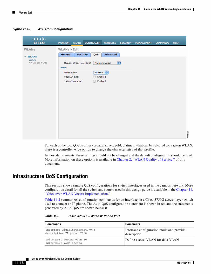
WLC QoS Configuration As mentioned in the “Cisco WLC QoS configuration” section on page 10-27, a dedicated voice VLAN should be defined on the controller for all VoIP handsets—that includes Vocera Badges. The voice VLAN should be configured for the highest possible quality of service by editing the VLAN and selecting the QoS tab.
As shown in Figure 11-16, Platinum (voice) should be selected on the Quality of Service (QoS) drop-down box. Vocera Badges do not support WMM so the WMM Policy drop-down box should be set to Optional.
11-17Voice over Wireless LAN 4.1 Design Guide
OL-14684-01
Chapter 11 Voice over WLAN Vocera Implementation Vocera QoS
Figure 11-16 WLC QoS Configuration
For each of the four QoS Profiles (bronze, silver, gold, platinum) that can be selected for a given WLAN, there is a controller-wide option to change the characteristics of that profile.
In most deployments, these settings should not be changed and the default configuration should be used. More information on these options is available in Chapter 2, “WLAN Quality of Service,” of this document.
Infrastructure QoS Configuration This section shows sample QoS configurations for switch interfaces used in the campus network. More configuration detail for all the switch and routers used in this design guide is available in the Chapter 11, “Voice over WLAN Vocera Implementation.”
Table 11-2 summarizes configuration commands for an interface on a Cisco 3750G access-layer switch used to connect an IP phone. The Auto-QoS configuration statement is shown in red and the statements generated by Auto-QoS are shown below it.
Table 11-2 Cisco 3750G —Wired IP Phone Port
Commands Comments
interface GigabitEthernet2/0/3 description IP phone 7960
Interface configuration mode and provide description
switchport access vlan 50 switchport mode access
Define access VLAN for data VLAN
11-18Voice over Wireless LAN 4.1 Design Guide
OL-14684-01

Chapter 11 Voice over WLAN Vocera Implementation Vocera QoS
Table 11-3 summarizes configuration commands for an interface on a Cisco 4503 access-layer switch used to connect an AP. The Auto-QoS configuration statement is shown in red and the statements generated by Auto-QoS are shown below it.
Table 11-4 summarizes configuration commands for an interface on a Cisco 4503 access-layer switch used as an uplink port to a distribution-layer switch. The Auto-QoS configuration statement is shown in red and the statements generated by Auto-QoS are shown below it.
switchport voice vlan 51 Define Voice VLAN
switchport port-security maximum 2 switchport port-security switchport port-security aging time 2 switchport port-security violation restrict switchport port-security aging type inactivity
Define Port Security features
spanning-tree portfast Spanning tree port configuration
auto qos voip cisco-phone Auto-QoS statement entered on all voice ports
srr-queue bandwidth share 10 10 60 20 srr-queue bandwidth shape 10 0 0 0 queue-set 2 mls qos trust device cisco-phone mls qos trust cos
Platform-specific QoS statements generated by the Auto-QoS statement that is in red in the line above.
Table 11-2 Cisco 3750G —Wired IP Phone Port (continued)
Commands Comments
Table 11-3 Cisco 4503—Access Point Port
Command Comments
interface FastEthernet2/16
(description ports connected to APs in Isolation Boxes)
Interface configuration mode and provide description.
switchport access vlan 48 switchport mode access
Define access VLAN for data VLAN all APs go on the access VLAN
auto qos voip trust Auto-QoS statement entered on all AP ports
qos trust dscp
(mls qos trust dscp is the equivalent command format for a Cisco 3750 switch.)
The Auto-QoS statement above sets the switch port to trust Layer-2 CoS (For nonrouted ports, the CoS value of the incoming packet is trusted. For routed ports, the DSCP value of the incoming packet is trusted).
This qos trust dscp command overrides that and sets the port to trust Layer-3 DSCP instead. The link between the AP and the switch port is not trunked and does not mark L2 CoS
tx-queue 3 bandwidth percent 33 priority high shape percent 33 service-policy output autoqos-voip-policy
Platform-specific QoS statements generated by the Auto-QoS statement that is in red in the line above.
11-19Voice over Wireless LAN 4.1 Design Guide
OL-14684-01
Chapter 11 Voice over WLAN Vocera Implementation Vocera QoS
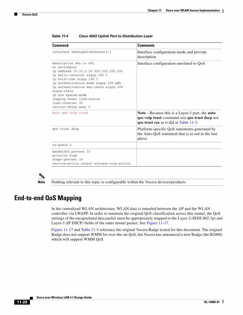
Note Nothing relevant to this topic is configurable within the Vocera devices/products.
End-to-end QoS Mapping In the centralized WLAN architecture, WLAN data is tunneled between the AP and the WLAN controller via LWAPP. In order to maintain the original QoS classification across this tunnel, the QoS settings of the encapsulated data packet must be appropriately mapped to the Layer-2 (IEEE 802.1p) and Layer-3 (IP DSCP) fields of the outer tunnel packet. See Figure 11-17.
Figure 11-17 and Table 11-5 reference the original Vocera Badge tested for this document. The original Badge does not support WMM for over-the-air QoS, but Vocera has announced a new Badge (the B2000) which will support WMM QoS.
Table 11-4 Cisco 4503 Uplink Port to Distribution Layer
Command Comments
interface TenGigabitEthernet1/1 Interface configuration mode and provide description
description A4L to D3L no switchport ip address 10.33.3.10 255.255.255.252 ip hello-interval eigrp 100 1 ip hold-time eigrp 100 3 ip authentication mode eigrp 100 md5 ip authentication key-chain eigrp 100 eigrp-chain ip pim sparse-mode logging event link-status load-interval 30 carrier-delay msec 0
Interface configuration unrelated to QoS
auto qos voip trust Note—Because this is a Layer-3 port, the auto qos voip trust command sets qos trust dscp not qos trust cos as it did in Table 11-3.
qos trust dscp Platform-specific QoS statements generated by the Auto-QoS statement that is in red in the line above
tx-queue 3
bandwidth percent 33 priority high shape percent 33 service-policy output autoqos-voip-policy
11-20Voice over Wireless LAN 4.1 Design Guide
OL-14684-01

Chapter 11 Voice over WLAN Vocera Implementation Vocera QoS
Figure 11-17 End-to-end QoS Packet Marking Mappings
The original IP packet DSCP and user-data sent by the WLAN client to the AP or received by the controller from the wired network infrastructure are transmitted across the LWAPP tunnel between the AP and the controller unaltered; the Layer-2 and Layer-3 QoS markings are only changed on the headers that encapsulate the original IP packet.
LWAPP Tunnel
802.1p DSCP Payload
LWAPP2
DSCP Payload
DSCP Payload DSCP DSCP PayloadLWAPP Encapsulated
DSCP DSCP PayloadLWAPP Encapsulated
802.1p
4
1
3
2229
79
802.1p DSCP Payload
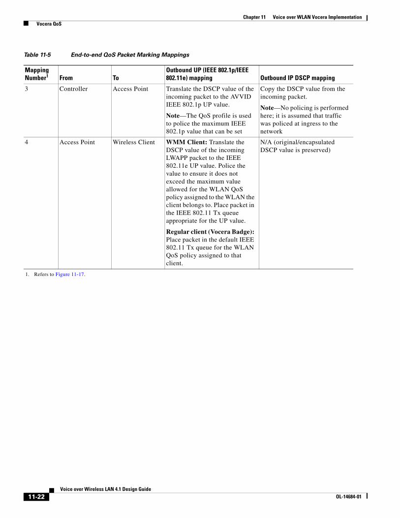
Table 11-5 End-to-end QoS Packet Marking Mappings
Mapping Number1 From To
Outbound UP (IEEE 802.1p/IEEE 802.11e) mapping Outbound IP DSCP mapping
1 Access Point Controller N/A (APs do not support IEEE 802.1Q / IEEE 802.1p tags on the wired interface)
WMM Client: Police the IEEE 802.11e UP value to ensure it does not exceed the maximum value allowed for the QoS policy assigned to that client; translate the value to the DSCP value.
Regular Client (Vocera Badge): Use the IEEE 802.11e UP value for the QoS policy assigned to that clients WLAN; translate the value to the DSCP value.
2 Controller Ethernet Switch Translate the DSCP value of the incoming LWAPP packet to the IEEE 802.1p UP value.
Note—The AP has policed the upstream DSCP (when it mapped from IEEE 802.1p UP to DSCP)
N/A (The original/encapsulated DSCP value is preserved)
Note—The DSCP is un-policed; it is whatever was set by the WLAN client.
11-21Voice over Wireless LAN 4.1 Design Guide
OL-14684-01
Chapter 11 Voice over WLAN Vocera Implementation Vocera QoS
3 Controller Access Point Translate the DSCP value of the incoming packet to the AVVID IEEE 802.1p UP value.
Note—The QoS profile is used to police the maximum IEEE 802.1p value that can be set
Copy the DSCP value from the incoming packet.
Note—No policing is performed here; it is assumed that traffic was policed at ingress to the network
4 Access Point Wireless Client WMM Client: Translate the DSCP value of the incoming LWAPP packet to the IEEE 802.11e UP value. Police the value to ensure it does not exceed the maximum value allowed for the WLAN QoS policy assigned to the WLAN the client belongs to. Place packet in the IEEE 802.11 Tx queue appropriate for the UP value.
Regular client (Vocera Badge): Place packet in the default IEEE 802.11 Tx queue for the WLAN QoS policy assigned to that client.
N/A (original/encapsulated DSCP value is preserved)
1. Refers to Figure 11-17.
Table 11-5 End-to-end QoS Packet Marking Mappings
Mapping Number1 From To
Outbound UP (IEEE 802.1p/IEEE 802.11e) mapping Outbound IP DSCP mapping
11-22Voice over Wireless LAN 4.1 Design Guide
OL-14684-01