vogt valves: a treatise on leakage - flowserveweb21.flowserve.com/files/files/literature/...vogt...
TRANSCRIPT

Experience In Motion
CONNECTION BULLETIN
Vogt Valves: A Treatise on LeakageFCD VVABR1013-00 – 01/05 (Replaces CB-13)

Vogt Valves: A Treatise on Leakage FCD VVABR1013-00 – 01/05
2
NomenclatureUnless otherwise stated, all symbols used in this article are defi ned as follows:
Symbol Meaning
d Internal diameter of pipe/capillary, in inches.
D Internal diameter of pipe/capillary, in feet.
f Friction factor for piping.
g Acceleration of gravity = 32.2 feet per second per second or 32.2 ft/sec2.
hL Loss of static pressure head due to fl uid fl ow, in feet of fl uid.
K Resistance coeffi cient or velocity head loss in the formula h = KV2/2g.
KL Resistance coeffi cient for leak path for use in laminar fl ow equation.
L Length of pipe, in feet.
Li Length of capillary/pipe, in inches.
qs Rate of liquid fl ow, in cubic inches per second at fl owing conditions.
q´s Rate of gas fl ow, in cubic inches per second at standard conditions (14.7 psia @ 60°F).
Qg Leakage rate of gas across a leak path, in cubic inches per second at standard conditions (scis, 14.7 psia @ 60°F).
QL Leakage rate of liquid across a leak path, in cubic inches per second at fl owing conditions.
m Molecular weight of gas.
P Pressure, in pounds per square foot.
P´a Average pressure across a capillary/pipe or leak path, in pounds per square inch absolute (psia).
Re Reynolds number
Sg Specifi c gravity of gas relative to air = the ratio of the molecular weight of the gas to that of air.
v Mean velocity of fl ow, in feet per second.
∆P Differential pressure across capillary/pipe or leak path, in psi.
MU (µ) Absolute (dynamic) viscosity, in centipoise.
RHO (ℓ) Weight density of fl uid, in pounds per cubic foot. For water = 62.4 lb/ft3.
SIGMA (σ) Surface tension of liquid to air interface, in lb/ft.
} Proportional to...
A Treatise on Leakge

3
Vogt Valves: A Treatise on Leakage FCD VVABR1013-00 – 01/05
fl owserve.com
AbstractLaminar type leakage across leak paths occurs with such a frequency that countable “drops” of liquid or “bubbles” of gas leakage can be observed and volume determined. Some leak paths will leak gas but will not leak a liquid such as water.
This paper discusses the theoretical aspects of liquid and isothermal gas laminar fl ow across theoretical capillaries. The importance of surface tension, viscosity and pressure differential to fl ow (or leakage) of gases and liquids is theoretically presented. Leakage equations based on the laminar fl ow equations and utilizing a resistance factor (KL) for leak paths are presented, and can be used to compare liquid and gas leakage across a given leak path.
Using the theoretical equations presented in the paper, some general observations are presented that explain why air leakage exceeds water leakage and why testing a product with water may not always fi nd the product that leaks in a gas service.
About the AuthorMr. Jolly is chief engineer of the Valve Division at Flowserve Vogt Valves. He is a registered professional engineer in the state of Kentucky. He holds a BS degree in mechanical engineering from the University of Kentucky and an MA degree in mathematics from the University of Louisville.
He is active in the American Society of Mechanical Engineers (ASME), the American Petroleum Institute (API), the Valve Manufacturers Association (VMA), and the Manufacturing Standardization Society of the Valve and Fitting Industry (MSS). He currently serves as president.
IntroductionThis article gives some practical and theoretical considerations that can be used in evaluating leakage. Laminar type leaks are discussed; especially the relationship that exists between gas and liquid leakage. From the information given, a comparative leakage analysis can be conducted on a laminar type leak path. Since a leakage path has no uniqueness as it relates to equipment, the concepts given in this article may be applied to leakage of valves, pumps, tanks, pressure vessels, etc. It is not the intention of this article to present a series of theoretical equations in which exact leakage rates across a leak path can be calculated, but to present a general method that can be used to predict or compare gas and liquid leakage across a leak path whose leak rate has been specifi ed or has been established by some leakage method.
Defi nitionLeakage as used in this article is defi ned as fl ow per unit of time. Specifi cally, the leakage to be addressed is the type of fl ow that emanates from a leak path in a pressurized product that produces countable and/or measurable “drops” of liquid or “bubbles” of gas (when tested under water) over a measured period of time.
Volumetric changes to liquids do not appreciably change as they fl ow from a pressurized product through a leak path to the atmosphere. Due to compressibility of gases, large volumetric increases occur in gas fl ow as the pressure drops across the leak path; and very small leak rates are perceived as large because they are observed as “bubbles” at atmospheric conditions (14.7 psia @ ambient temperature). Since a unit of leaking gas from a pressurized product has its greatest natural volume at atmospheric conditions, the leakage observed is in its worst case condition.
Vogt Valves: A Treatise on Leakage FCD VVABR1013-00 – 01/05
4
Gas leakage, as used in this paper, is defi ned as the volume of gas that passes through a leak path, observed and measured at standard conditions (14.7 psia @ 60°F) over a measured period of time. See Figures 1A and 1B.
TheoreticalBy theoretical methods we can set up common ground on which to discuss this leakage in drops and bubbles per unit of time and to establish the leakage rate occurring across a leakage path. Since the volume of a “drop of liquid” or a “bubble of gas” can be calculated, based on the assumption that they are spherical in nature, and time can be measured, leakage rates can be calculated. Table 1 gives the volume and leakage rates for various bubble or drop diameters when developing at various intervals of time.
From a practical standpoint, the diameter of a “drop” or “bubble” observed by an inspector (tester), operator or maintenance man of a piece of equipment is not known and really not important to the analysis presented herein. The usually mentioned “drops/minute” or “bubbles/minute” explanation of leakage with an estimated diameter is accurate enough as it relates to comparison of leakage given in this paper. Very close accuracy of the volumetric leak rates can be obtained by methods illustrated in Figures 1A and 1B. These leakage rates can be theoretically equated to “drop” or “bubble” diameter by correlating the drops or bubbles per minute to the volume collected over a measured length of time.
A theoretical review of some basics of fl uid mechanics is required as we develop our basis for analyzing leakage. Any good text on fl uid mechanics indicates that fl ow through pipe and capillaries can be characterized by one of the following fl ow modes:
Turbulent The fl ow stream is characterized by fl ow particles moving randomly in magnitude and direc-tion in the fl ow stream. Turbulent fl ow exists for fl ow rates in conduits in which Re > 4000. Turbulent fl ow is the most common fl ow mode and normally occurs in piping systems designed to move fl uids.
Laminar Sometimes known as streamline fl ow because particles of fl uid move along the conduit in straight, parallel laminar layers. Laminar fl ow exists for fl ow rates in conduits in which Re~2000. Laminar fl ow may occur in piping systems that move highly viscous fl uids at low velocities.
Transition The fl ow stream is unpredictable in that either laminar or turbulent modes may exist. Transition fl ow occurs in a Reynolds number range of 2000–4000.
It can be shown that the leakage rate ranges that are addressed in Table 1 (countable drops or bubbles) include leaks that are in the Laminar Flow Range. This can be done by a comparison analysis of fl ow rates across theoretical capillaries that have fi xed dimensions and can be theoretically analyzed, to those in Table 1 and showing that such fl ow rates have Reynolds numbers in the laminar fl ow region. Unlike capillaries, leak paths cannot be described by exact dimensions. Their dimensions and geometries are generally unknown. Even the fl ow direction and cross-section may vary across the leak path. There are no pure theoretical equations available to calculate fl ow rates across leak paths. Empirical methods must be used to show that the fl ow across a leak path is laminar. Modifi ed theoretical equations may be used to predict the leakage rate across leak paths that have been experimentally evaluated. The treatment of fl ow through valves and other similar products, in the turbulent fl ow mode, and the modifi cation of theoretical fl ow equation to include a fl ow resistance factor (K) will be used to support the use of a resistance factor (KL) for laminar leak paths. Since the leak rates addressed in Table 1 parallel laminar fl ow across capillaries, the KL resistance factor for leaks will be applied to the theoretical laminar fl ow equations.
Some well-known general equations* for fl ow through pipe or capillaries for the Turbulent and Laminar Flow Modes described above are needed to develop a theoretical position on leakage.
5
Vogt Valves: A Treatise on Leakage FCD VVABR1013-00 – 01/05
fl owserve.com
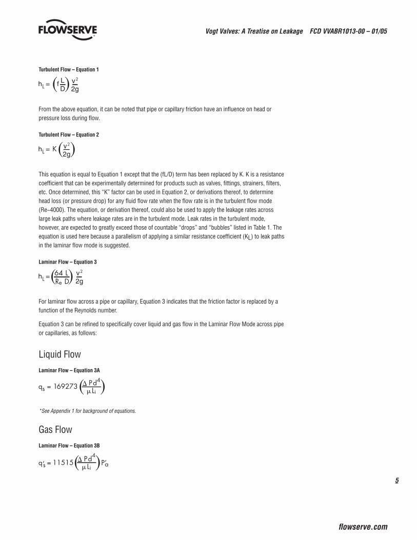
Turbulent Flow – Equation 1
From the above equation, it can be noted that pipe or capillary friction have an infl uence on head or pressure loss during fl ow.
Turbulent Flow – Equation 2
This equation is equal to Equation 1 except that the (fL/D) term has been replaced by K. K is a resistance coeffi cient that can be experimentally determined for products such as valves, fi ttings, strainers, fi lters, etc. Once determined, this “K” factor can be used in Equation 2, or derivations thereof, to determine head loss (or pressure drop) for any fl uid fl ow rate when the fl ow rate is in the turbulent fl ow mode (Re~4000). The equation, or derivation thereof, could also be used to apply the leakage rates across large leak paths where leakage rates are in the turbulent mode. Leak rates in the turbulent mode, however, are expected to greatly exceed those of countable “drops” and “bubbles” listed in Table 1. The equation is used here because a parallelism of applying a similar resistance coeffi cient (KL) to leak paths in the laminar fl ow mode is suggested.
Laminar Flow – Equation 3
For laminar fl ow across a pipe or capillary, Equation 3 indicates that the friction factor is replaced by a function of the Reynolds number.
Equation 3 can be refi ned to specifi cally cover liquid and gas fl ow in the Laminar Flow Mode across pipe or capillaries, as follows:
Liquid FlowLaminar Flow – Equation 3A
*See Appendix 1 for background of equations.
Gas Flow Laminar Flow – Equation 3B

Vogt Valves: A Treatise on Leakage FCD VVABR1013-00 – 01/05
6
Since the Reynolds number is important to leak rate analysis, the general equations for Reynolds number are given as follows:
Reynolds Number – Equation 4
Liquid Flow – Equation 4A
Gas Flow – Equation 4B
The above equations shall be used in fl ow calculations of capillaries to show that the fl ow rates noted in Table 1 lead to Reynolds numbers in the Laminar Flow Range.
The viscosity of the fl owing fl uid is also important in laminar fl ow analysis. Tables 2, 3 and 4 list viscosi-ties of many common liquids and gases.
Example 1 –Water/Air Flow ComparisonFrom Equation 3A, we can calculate the fl ow rate of water at 100 psig @ 60°F across a .002" diameter capillary, 1" long, as follows:
which is the equivalent of approximately 16 drops per minute (1⁄8" diameter) from the capillary. See Table 1.
The Reynolds number for this fl ow rate can be calculated from Equation 4A, as follows:
Since Re = 87 is less than 2000, the fl ow is laminar.

7
Vogt Valves: A Treatise on Leakage FCD VVABR1013-00 – 01/05
fl owserve.com
From Equation 3B, we can calculate the fl ow rate of air at 100 psig @ 50°F across the same .002" diameter capillary, 1" long, as follows:
which greatly exceeds any of the bubble rates noted in Table 1. In fact, the bubble rate of this leak would not be countable, forming the equivalent of 3448 – 1⁄8" bubbles per minute.
The Reynolds number for this fl ow rate can be calculated from Equation 4B, as follows:
which is less than 2000 and is in the laminar range. Comparison of the two calculations leads to the fi rst obvious conclusion:
The fl ow of air @ 60°F versus that of water @ 60°F across the same capillary at the same pressure drop is greatly different. In fact, Equations 3A and 3B can be equated to show that 60°F water fl ow across the same capillary at an equal pressure drop can be generalized as follows:
Air/Water Flow Comparison – Equation 5
This equation indicates air fl ow measured in bubbles passing through a capillary would be 245 times greater than water in equivalent size drops passing through the same capillary when both are at a pressure of 100 psig. The difference between air and water fl ow across a capillary becomes even greater as the pressure drop and average pressure increase.
Example 2 – Air/Water Flow ComparisonTo make a further comparison of air/water fl ow, the fl ow across a 1" long capillary that is fl owing 500 psig air @ 60°F at 8.5 x 10⁻⁵ scis (or 11⁄8" diameter bubble every 12 sec) is compared with water fl ow at the same conditions. See Table 1. What is the likelihood that this capillary would fl ow water?
This calculation requires the arrangement of Equation 3B to read as follows:
* Standard cubic inch/second = scis.

Vogt Valves: A Treatise on Leakage FCD VVABR1013-00 – 01/05
8
From this equation, the diameter of the capillary that will permit air fl ow at the above rate can be calculated, as follows:
Now that the diameter that will fl ow this small volume of air has been calculated, calculate the volume of water at the same conditions (500 psig @ 60°F) that will fl ow across the same capillary:
From Equation 3A:
At this low fl ow, it would require 3.69 hours for the equivalent of 1 drop (1⁄8" diameter) of water to pass through the capillary. From a practical standpoint, this water fl ow would never be detected by visual means. One bubble of air fl ow every 12 seconds is expected to be visually detectable and illustrates the advantage of using air as a test medium in lieu of water.
Surface Tension – Capillary FlowIt has been suggested that surface tension may be the reason for the tremendous difference in air fl ow versus water fl ow across capillaries. Surface tension of water fl ow through a capillary with a round fl ow cross-section venting to the atmosphere can be calculated by use of the following general formula:
Surface Tension – Equation 6
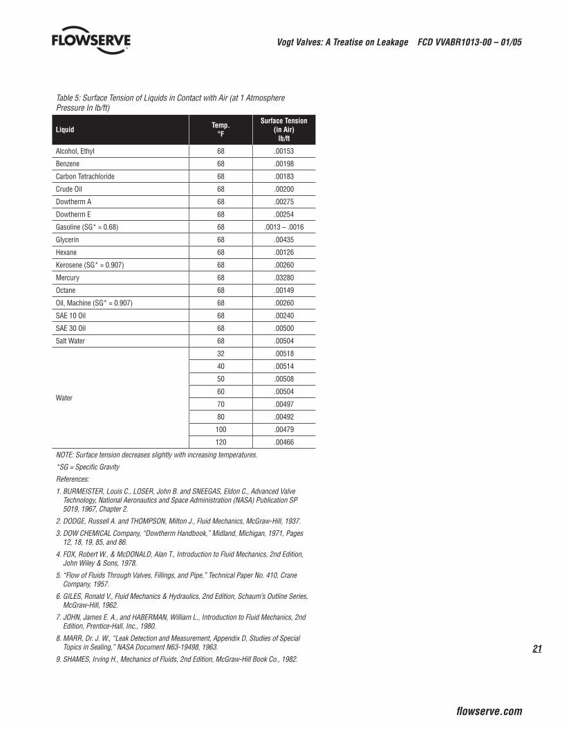
This formula clearly indicates that as the diameter of the capillary decreases, the pressure to overcome the surface tension increases. If the pressure drop across the capillary is greater than the surface tension, fl ow is expected to take place. Note that the length of the capillary would not affect this calcula-tion, only the diameter of the capillary in which the liquid is fl owing. The surface tension σ for a number of liquids is shown in Table 5. Equation 6 can be applied to water fl ow for the capillary in Example 2 above, as follows:
This calculation indicates that 9.38 psi is required to overcome the surface tension in the 1.79 x 10⁻⁴" capillary. For pressure drops less than 9.38 psi, surface tension would not allow water fl ow to occur. For high pressure drops, it can be concluded that the main reason that water fl ow is retarded across the 1.79 x 10⁻⁴" capillary more so than air is because of the high viscosity of water relative to air and not

9
Vogt Valves: A Treatise on Leakage FCD VVABR1013-00 – 01/05
fl owserve.com
because of surface tension. Surface tension would not stop a fl ow of water at 500 psig, as the above calculation indicates.
For surface tension to play a signifi cant role in the fl ow of 60°F water at high pressure across a capillary, the diameter of the capillary needs to be in the 1 x 10⁻⁶ inch range, as illustrated by the following calculation:
This calculation indicates that a pressure drop of 1680 psig would be required just to overcome the effects of surface tension.
Laminar Flow Range/CapillariesIt can be established that the leak rates illustrated in Table 1 for 60°F water are in the Laminar Flow Range as long as the following ratio calculated from Equation 4A for Re 2000 is satisfi ed:
Flow/Capillary Diameter Ratio (Water) – Equation 4C
Likewise, Equation 4B can be used to show that the leak rates illustrated in Table 1 for 60°F air are in the Laminar Flow Range, as long as the following ratio is satisfi ed:
Flow Capillary Diameter Ratio (Air) – Equation 4D
As long as the above ratios are met, 60°F water and air fl ow in capillaries are in the laminar fl ow mode. If the ratios are exceeded, the fl ow mode will be in the transition or turbulent fl ow modes.
Leakage MechanicsMoving away from theoretical analysis of capillary fl ow but making a modifi cation of those equations to apply to leak paths seems logical.
Since leak paths, areas, geometries, fl ow cross-sections and diameters vary, the laminar fl ow equations for capillary fl ow cannot be used to calculate leakage. The modifi cation of Equation 1 to Equation 2 typically for valves for turbulent fl ow, suggests that a similar approach for fl ow across laminar fl ow leak paths can be used. The experimentally determined resistance factor (K) for valves with varying fl ow path geometries and characteristics paralleling what might be expected in leak paths has been used for many years to determine fl ow and/or pressure drop for valves.
Vogt Valves: A Treatise on Leakage FCD VVABR1013-00 – 01/05
10
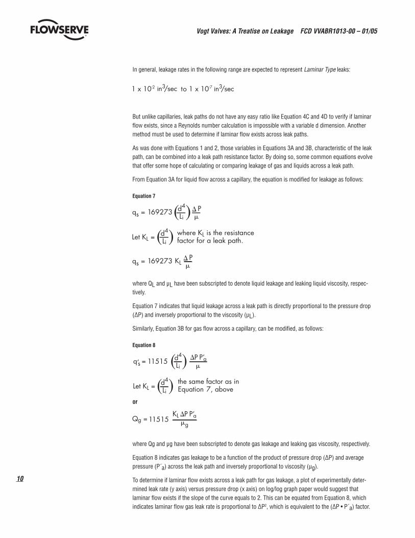
In general, leakage rates in the following range are expected to represent Laminar Type leaks:
But unlike capillaries, leak paths do not have any easy ratio like Equation 4C and 4D to verify if laminar fl ow exists, since a Reynolds number calculation is impossible with a variable d dimension. Another method must be used to determine if laminar fl ow exists across leak paths.
As was done with Equations 1 and 2, those variables in Equations 3A and 3B, characteristic of the leak path, can be combined into a leak path resistance factor. By doing so, some common equations evolve that offer some hope of calculating or comparing leakage of gas and liquids across a leak path.
From Equation 3A for liquid fl ow across a capillary, the equation is modifi ed for leakage as follows:
Equation 7
where QL and μL have been subscripted to denote liquid leakage and leaking liquid viscosity, respec-tively.
Equation 7 indicates that liquid leakage across a leak path is directly proportional to the pressure drop (∆P) and inversely proportional to the viscosity (μL).
Similarly, Equation 3B for gas fl ow across a capillary, can be modifi ed, as follows:
Equation 8
or
where Qg and μg have been subscripted to denote gas leakage and leaking gas viscosity, respectively.
Equation 8 indicates gas leakage to be a function of the product of pressure drop (∆P) and average pressure (P´a) across the leak path and inversely proportional to viscosity (μg).
To determine if laminar fl ow exists across a leak path for gas leakage, a plot of experimentally deter-mined leak rate (y axis) versus pressure drop (x axis) on log/log graph paper would suggest that laminar fl ow exists if the slope of the curve equals to 2. This can be equated from Equation 8, which indicates laminar fl ow gas leak rate is proportional to ∆P2, which is equivalent to the (∆P • P´a) factor.

11
Vogt Valves: A Treatise on Leakage FCD VVABR1013-00 – 01/05
fl owserve.com
A logarithmic conversion of the equation would show that the slope of 2 could be expected. Likewise for liquid leakage, Equation 7 would indicate that a leak rate/pressure drop plot on log/log graph paper would have a slope of 1.
Equations 7 and 8 suggest that if a leakage rate for a leak path can be determined for a liquid or gas having a known viscosity and pressure drop, a resistance factor (KL) can be determined for the leak path. This KL factor can be used in Equations 7 or 8 to predict or compare the leakage across the same leak path at different pressure drops, or for a different type liquid and/or gas. Clearly, viscosity of the leaking fl uid is the principal factor to be considered when comparing leakage rates. A comparison of gas to liquid leakage across the same leak path can be equated from Equations 7 and 8, as follows:
or
Comparative Gas/Liquid Leakage – Equation 9
where P´a is average absolute pressure across the gas leak path and ∆Pg and ∆PL have been subscripted to denote pressure drop across the gas leak path and liquid leak path, respectively.
For the special case where the pressure drop across the leak path for gas and liquid is equal, Equation 9 can be further simplifi ed, as follows:
Comparative Gas/Liquid Leakage – Equation 9A
Not readily evident by this equation is that the leakage of air across a given leak path is several orders of magnitude greater than water because of its lower viscosity and expansion characteristic. As an example, the comparative leakage of 1000 psig air @ 60°F versus 1000 psig water @ 60°F across the same leakage path can be calculated from Equation 9A, as follows:
meaning that air would leak at a rate of 2166 times greater than water at the stated conditions.

Vogt Valves: A Treatise on Leakage FCD VVABR1013-00 – 01/05
12
Equation 9 also indicates that a 46 psig air test would be just as effective as a 6000 psig water test in determining leakage across the same leak path, calculated as follows:
meaning that 46 psig air would leak at the same rate as 6000 psig water across the same leak path.
Surface Tension/Leak PathsThe effect of surface tension on leak paths is probably greater than on capillaries because many leak paths have a slit cross-section. The pressure to overcome surface tension can be two to three times greater for leak paths that have a slit cross-section than a capillary with its round cross-section.
The comparative pressure to overcome surface tension in a slit leak path versus a capillary with the same cross-sectional area can be equated as follows:
Equation 10
where
Ps = Surface Tension Pressure (Slit)
R = Ratio of Length/Width of Slit
Pc = Surface Tension Pressure (Capillary)
Some information suggests that no visible water leak when dry air at the same pressure will leak at the rate of 1.00 x 10⁻⁴ in3/sec, probably due to surface tension.
As the above calculations on capillaries indicate, it may not be due to surface tension but more due to the viscosity of water.
Vogt’s own testing has discovered leaks that leak during high pressure (500 psig and 2000 psig) air testing in the 1.7 x 10⁻² to 7.4 x 10⁻² scis but will not pass water in any reasonable time period. These leaks, once tested with water, become plugged, probably due to surface tension or capillary action, and will not leak air until the water is driven from the leak path by a high-temperature furnace soak. This points up a disadvantage to testing with water prior to testing with air. Small leaks may become clogged with water and not leak on air test.
There is another gas leak fl ow method that is not addressed in this paper. This gas fl ow is known as Molecular Flow. Molecular fl ow across a leak path occurs by individual molecules and can be detected only by sophisticated electronic leak detection equipment such as a helium mass spectrometer. Such a small leak would be so small that “bubble” formation would not occur. Molecular fl ow is proportional to the ∆P across the leak path and inversely proportional to the square root of the leaking gas molecular weight, as follows:
The perception that the molecular weight (m) of a gas is the property most infl uencing leakage across a leak path applies to molecular leakage fl ow. As Equation 8 indicates, the critical gas property that
13
Vogt Valves: A Treatise on Leakage FCD VVABR1013-00 – 01/05
fl owserve.com
has the greatest infl uence on laminar leakage is the gas’s viscosity. For visible “bubble” type leakage, viscosity is the gas property that we must evaluate. Molecular type leakage could be the subject of another paper.
General ObservationsThe equations given in this paper generally apply to leak paths whose characteristics are not affected by pressure. The physical dimensions of the leak path remain fi xed and unaffected by pressure. Leaks are also equated on a volumetric basis.
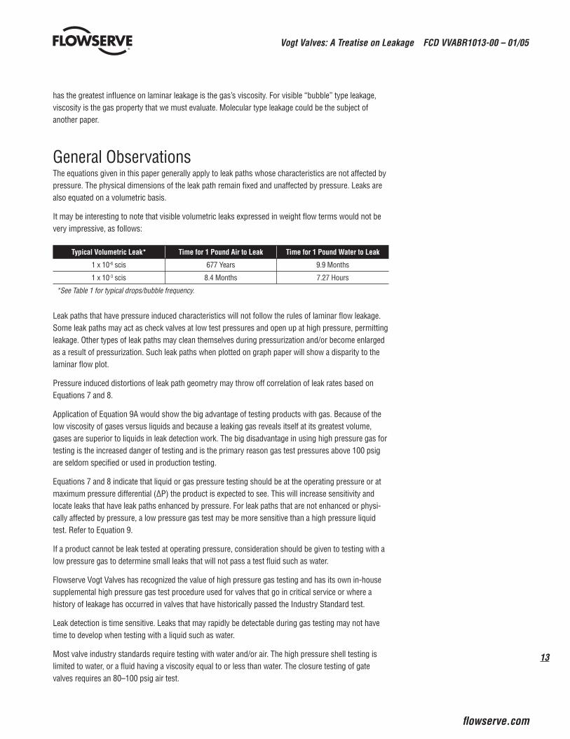
It may be interesting to note that visible volumetric leaks expressed in weight fl ow terms would not be very impressive, as follows:
Typical Volumetric Leak* Time for 1 Pound Air to Leak Time for 1 Pound Water to Leak
1 x 10⁻⁶ scis 677 Years 9.9 Months
1 x 10⁻³ scis 8.4 Months 7.27 Hours
*See Table 1 for typical drops/bubble frequency.
Leak paths that have pressure induced characteristics will not follow the rules of laminar fl ow leakage. Some leak paths may act as check valves at low test pressures and open up at high pressure, permitting leakage. Other types of leak paths may clean themselves during pressurization and/or become enlarged as a result of pressurization. Such leak paths when plotted on graph paper will show a disparity to the laminar fl ow plot.
Pressure induced distortions of leak path geometry may throw off correlation of leak rates based on Equations 7 and 8.
Application of Equation 9A would show the big advantage of testing products with gas. Because of the low viscosity of gases versus liquids and because a leaking gas reveals itself at its greatest volume, gases are superior to liquids in leak detection work. The big disadvantage in using high pressure gas for testing is the increased danger of testing and is the primary reason gas test pressures above 100 psig are seldom specifi ed or used in production testing.
Equations 7 and 8 indicate that liquid or gas pressure testing should be at the operating pressure or at maximum pressure differential (∆P) the product is expected to see. This will increase sensitivity and locate leaks that have leak paths enhanced by pressure. For leak paths that are not enhanced or physi-cally affected by pressure, a low pressure gas test may be more sensitive than a high pressure liquid test. Refer to Equation 9.
If a product cannot be leak tested at operating pressure, consideration should be given to testing with a low pressure gas to determine small leaks that will not pass a test fl uid such as water.
Flowserve Vogt Valves has recognized the value of high pressure gas testing and has its own in-house supplemental high pressure gas test procedure used for valves that go in critical service or where a history of leakage has occurred in valves that have historically passed the Industry Standard test.
Leak detection is time sensitive. Leaks that may rapidly be detectable during gas testing may not have time to develop when testing with a liquid such as water.
Most valve industry standards require testing with water and/or air. The high pressure shell testing is limited to water, or a fl uid having a viscosity equal to or less than water. The closure testing of gate valves requires an 80–100 psig air test.

Vogt Valves: A Treatise on Leakage FCD VVABR1013-00 – 01/05
14
Review of Tables 2 and 3 would indicate that water and air are very good choices as test fl uids because of their viscosity. Few liquids have a lower viscosity than water. Those that do would have economical and safety constraints limiting their use. Air is an economical choice as well.
Kerosene has also been used for many years as a testing medium because of its lubricating quality. A review of Equation 7 and viscosity Table 3 indicates that a leak path would leak twice as much water as kerosene in a given period of time. Table 5 would indicate a preference for kerosene over water if surface tension is considered.
Surface tension pressure (Equation 6) is a measure of a fl ow or leak path capillarity. The higher the surface tension pressure, the greater the leak path capability to draw in water and plug itself. Once plugged with water, a gas such as air is not expected to pass through the leak path unless it exceeds the surface tension pressure. Air testing when used to determine very small leaks should precede water testing.
As noted from Table 2, the viscosities of several gases normally used in testing—air, nitrogen and helium—are very similar. Therefore, a change in test gas will not markedly improve the sensitivity of leak detection using gas-under-water techniques.
Flowserve Vogt valves are tested to meet industry standards MSS-SP-61 and/or API-598. Both of these specs require high pressure testing of the shell. Normally, water is used as the test fl uid for safety reasons. Both of these standards give a good test, yet if a valve goes into a high pressure dry gas or steam service, the valve could still have a small leak not detectable during the water testing. The perception of the user is that the valve was not tested, but in reality, the lower viscosity of gases (Table 2) and steam (Table 4) pass through a leak path much more rapidly than water, as projected by Equations 9 or 9A.
The two industry standards noted above require that products be shell tested with water at a pressure 1.5 times the I00°F valve rating. In addition to leak tightness, this test would also verify the structural integrity of the product. Safety considerations do not permit the testing of many of these valves with a gas test to the 1.5 x I00°F valve rating requirement.
A review of Table 3 would indicate which liquids leak the greatest, as predicted by Equation 7. The smaller the viscosity of a liquid, the greater the leakage. A typical comparison would indicate that ammonia liquid would leak at a rate approximately ten times greater than water.
A review of Tables 2 and 4 and Equation 8 indicates which gases and vapors leak the greatest, as predicted by Equation 8. The smaller the viscosity of a gas, the greater the leakage. A typical comparison would indicate that hydrogen gas would leak at a rate approximately twice as great as air.
A review of Tables 2, 3 and 4 and Equation 9A indicates that almost all gases, including steam, leak at a greater rate than does water.

15
Vogt Valves: A Treatise on Leakage FCD VVABR1013-00 – 01/05
fl owserve.com
Because the viscosity of liquids decreases with increasing temperature, a product that has been tested with water at ambient temperature may leak if placed in similar service at a higher temperature. Example: A valve tested with 78°F water and placed in saturated water service may leak due to the difference in viscosity. Refer to Equation 7 and viscosity Table 3.
The viscosity of gas and vapors, including steam, increase with increasing temperature and, therefore, their tendency to leak decreases with increasing temperature.
Increasing the gas test ∆P across a leak path by a factor of 5 (100 psig to 500 psig) will increase the leakage rate by a factor of 25. Increasing the pressure across the leak path is the simplest method to improve leakage detection sensitivity. Refer to Equation 8.
Increasing the water test ∆P across a leak path by a factor of 5 (500 psig to 2500 psig), unlike gas testing, only increases the liquid leakage by a factor of 5. Refer to Equation 7.
If a detected gas leak is in the laminar fl ow range, extrapolation to higher internal pressures using the relationship Qg } ∆P2 may be carried out.
It is generally believed that leak paths that leak air at a rate less than 1 x 10⁻⁵ scis will not pass water. Flowserve Vogt’s testing confi rms this, but we have also experienced much larger leaks of air that will not pass water over any reasonable period of time.
Vogt has recorded water leaks at 2 cc/hr. (3.4 x 10⁻⁵ in3/sec) during extended test periods. Water leaks smaller than this are seldom ever observed and/or recorded, indicating that such a water leak is at the threshold of detectability or occurrence.
Figure 1A

Vogt Valves: A Treatise on Leakage FCD VVABR1013-00 – 01/05
16
Figure 1B

17
Vogt Valves: A Treatise on Leakage FCD VVABR1013-00 – 01/05
fl owserve.com
Table 1Drop or Bubble
Diameter
Volume (1) Drop/Bubble
Leak Rate (scis) (2) (3)
Drops/Bubbles per Minute
in. In3 4 5 6 8 10 16 20 25 32 50 64
1⁄32" 1.598 x 10⁻⁵ 1.06 x 10⁻⁶
1.33 x 10⁻⁶
1.59 x 10⁻⁶
2.13 x 10⁻⁶
2.66 x 10⁻⁶
4.26 x 10⁻⁶
5.33 x 10⁻⁶
6.65x 10⁻⁶
8.52 x 10⁻⁶
1.33 x 10⁻⁵
1.70 x 10⁻⁵
1⁄16" 1.278 x 10⁻⁴ 8.52 x 10⁻⁶
1.06 x 10⁻⁵
1.28 x 10⁻⁵
1.70 x 10⁻⁵
2.12 x 10⁻⁵
3.41 x 10⁻⁵
4.24 x 10⁻⁵
5.30 x 10⁻⁵
6.82 x 10⁻⁵
1.06 x 10⁻⁴
13.64 x 10⁻⁴
3⁄32" 4.314 x 10⁻⁴ 2.88 x 10⁻⁵
3.60 x 10⁻⁵
4.32 x 10⁻⁵
5.76 x 10⁻⁵
7.20 x 10⁻⁵
1.15 x 10⁻⁴
1.44 x 10⁻⁴
1.80 x 10⁻⁴
2.30 x 10⁻⁴
3.60 x 10⁻⁴
4.60 x 10⁻⁴
1⁄8" 1.023 x 10⁻³ 6.82 x 10⁻⁵
8.52 x 10⁻⁵
1.02 x 10⁻⁴
1.36 x 10⁻⁴
1.71 x 10⁻⁴
2.73 x 10⁻⁴
3.42 x 10⁻⁴
4.26 x 10⁻⁴
5.45 x 10⁻⁴
8.52 x10⁻⁴
1.09 x 10⁻³
5⁄32" 1.997 x 10⁻³ 1.33 x 10⁻⁴
1.66 x 10⁻⁴
2.00 x 10⁻⁴
2.66 x 10⁻⁴
3.33 x 10⁻⁴
5.32 x 10⁻⁴
6.66 x 10⁻⁴
8.30 x 10⁻⁴
1.06 x 10⁻³
1.66 x 10⁻³
2.12 x 10⁻³
3⁄16" 3.451 x 10⁻³ 2.30 x 10⁻⁴
2.88 x 10⁻⁴
3.45 x 10⁻⁴
4.6 x 10⁻⁴
5.75 x 10⁻⁴
9.2 x 10⁻⁴
1.15 x 10⁻³
1.44 x 10⁻³
1.84 x 10⁻³
2.88 x 10⁻³
3.68 x 10⁻³
1) Volume of drop or bubble = π/6 (diameter)3
2) Standard Cubic Inch per Second Leakage.
3) Standard in scis refers to the collection of bubbles in gas-under-water type tests in which the visible bubble is observed or collected at standard condi-tions – 14.7 psia @ 60°F.
Since the volume of a leaking liquid does not change across a leak path, the leak rates noted above are equal to in3/sec when referring to liquid leakage rates.

Vogt Valves: A Treatise on Leakage FCD VVABR1013-00 – 01/05
18
Table 2: Viscosity of Gases and Vapors (at Atmospheric Pressure)
Gas/Vapor Viscosity (Centipoise) Temp. °F
Acetylene .010 70
Ammonia .010 70
Argon .021 32
Benzene .009 177
Butane .008 70
Carbon Dioxide .015 70
Carbon Monoxide .014 70
Chlorine .013 70
Chloroform .011 143
Dowtherm A .0092 400
Dowtherm E .0012 400
Ethane .010 70
Ethylene .010 70
Freon 11 .010 70
Freon 12 .013 70
Freon 113 .013 80
Freon 114 .015 80
Helium .020 70
Hydrogen .009 70
Hydrogen Chloride .014 32
Hydrogen Sulfi de .012 32
Methane .011 70
Neon .030 32
Nitrogen .018 70
Propane .008 32
Oxygen .020 70
Sulfur Dioxide .013 70
Water Vapor .013 212
Viscosity of Air (at Atmospheric Pressure – In Centipoise)Temp. °F Viscosity (Centipoise)
0 .016
40 .017
60 .018
100 .019
120 .020
NOTE: The viscosity of gases increases with increasing tempera-ture and is negligently affected by pressure except at extremely high pressures.

19
Vogt Valves: A Treatise on Leakage FCD VVABR1013-00 – 01/05
fl owserve.com
Table 3: Viscosity of Liquids (at Atmospheric Pressure)
Liquid Viscosity (Centipoise) Temp. °F
Acetic Acid 1.04 86
Alcohol-Allyl 1.17 86
Alcohol-Ethyl 1.20 86
Alcohol-Isopropyl 2.00 80
Alcohol-Methyl .60 86
Ammonia .10 80
Benzene .65 70
.50 100
Benzol .57 86
Brine, CaCl (20% Salt) 2.30 70
1.30 100
Brine, NaCl (20% Salt) 2.00 70
1.40 100
Bromide .91 86
Butane .18 60
Butyric Acid 1.30 86
Carbon Disulfi de .35 86
Carbon Tetrachloride
.97 70
.74 100
.85 86
Chlorine Trifl uoride .41 77
Chloroform .52 86
Dowtherm A 2.60 100
Dowtherm A .38 400
Dowtherm E 1.05 100
Dowtherm E .27 400
Ethane .05 60
Ethyl Bromide .37 86
Ethyl Ether .22 86
Ethylene Bromide 1.48 86
Ethylene Chloride .74 86
Ethylene Glycol 19.90 68
Formic Acid 1.46 86
Freon 11 .42 80
Freon 12 .26 80
Freon 113 .65 80
Freon 114 .37 80
Gasoline (SIG. 0.68) .28 70
Glycerol 207.00 68
Glycerine 830.00 68.54
Heptane .38 86
Hexane .30 86
Hydrazine .90 77
Liquid Viscosity (Centipoise) Temp. °F
Kerosene2.10 60
1.90 77
Linseed Oil 3.10 86
Mercury 1.50 80
Methyl Chloride .25 80
Methyl Iodine .46 86
Nitrogen Tetraoxide .34 100
Oxtane .48 86
Pentame .22 86
Propane .15 60
Propionic Acid .96 86
Propyl Alcohol 1.78 86
RP-1 Fuel 1.17 100
SAE 10 Lube Oil 2.00 60
SAE 30 Lube Oil 450.00 60
Sodium Hydroxide (20%) 3.50 80
Sulfuric Acid (20%) 1.30 80
Toluene .52 86
Tupentine 1.27 86
Water
1.80 32
1.55 40
1.31 50
1.13 60
.98 70
.86 80
.80 86
.68 100
.56 120
.43 150
.31 200
.28* 212
.19* 300
.14* 400
.095* 500
.065* 600
1) The viscosity of liquids decreases with increasing temperatures.
2) The viscosity of liquids is negligently affected by pressure except at extremely high pressures.
*At Saturated Pressure.

Vogt Valves: A Treatise on Leakage FCD VVABR1013-00 – 01/05
20
Table 4: Viscosity of Steam
Pressure (psig) Temp. °F Viscosity (Centipoise)
Saturated (1)
0 212 .014
100 338 .017
400 448 .021
600 488 .024
800 520 .027
1200 569 .032
Superheated (2)
100 800 .025
100 1000 .028
400 800 .027
400 1000 .030
600 800 .028
600 1000 .031
800 800 .029
800 1000 .032
1200 800 .032
1200 1000 .034
1) Viscosity of Saturated Steam increases with increasing pres-sure and temperature.
2) Viscosity of Superheated Steam at pressure less than 800 psig increases with increased superheat.
21
Vogt Valves: A Treatise on Leakage FCD VVABR1013-00 – 01/05
fl owserve.com
Table 5: Surface Tension of Liquids in Contact with Air (at 1 Atmosphere Pressure In lb/ft)
Liquid Temp.°F
Surface Tension (in Air)
lb/ft
Alcohol, Ethyl 68 .00153
Benzene 68 .00198
Carbon Tetrachloride 68 .00183
Crude Oil 68 .00200
Dowtherm A 68 .00275
Dowtherm E 68 .00254
Gasoline (SG* = 0.68) 68 .0013 – .0016
Glycerin 68 .00435
Hexane 68 .00126
Kerosene (SG* = 0.907) 68 .00260
Mercury 68 .03280
Octane 68 .00149
Oil, Machine (SG* = 0.907) 68 .00260
SAE 10 Oil 68 .00240
SAE 30 Oil 68 .00500
Salt Water 68 .00504
Water
32 .00518
40 .00514
50 .00508
60 .00504
70 .00497
80 .00492
100 .00479
120 .00466
NOTE: Surface tension decreases slightly with increasing temperatures.
*SG = Specifi c Gravity
References:
1. BURMEISTER, Louis C., LOSER, John B. and SNEEGAS, Eldon C., Advanced Valve Technology, National Aeronautics and Space Administration (NASA) Publication SP 5019, 1967, Chapter 2.
2. DODGE, Russell A. and THOMPSON, Milton J., Fluid Mechanics, McGraw-Hill, 1937.
3. DOW CHEMICAL Company, “Dowtherm Handbook,” Midland, Michigan, 1971, Pages 12, 18, 19, 85, and 86.
4. FOX, Robert W., & McDONALD, Alan T., Introduction to Fluid Mechanics, 2nd Edition, John Wiley & Sons, 1978.
5. “Flow of Fluids Through Valves, Fillings, and Pipe,” Technical Paper No. 410, Crane Company, 1957.
6. GILES, Ronald V., Fluid Mechanics & Hydraulics, 2nd Edition, Schaum’s Outline Series, McGraw-Hill, 1962.
7. JOHN, James E. A., and HABERMAN, William L., Introduction to Fluid Mechanics, 2nd Edition, Prentice-Hall, Inc., 1980.
8. MARR, Dr. J. W., “Leak Detection and Measurement, Appendix D, Studies of Special Topics in Sealing,” NASA Document N63-19498, 1963.
9. SHAMES, Irving H., Mechanics of Fluids, 2nd Edition, McGraw-Hill Book Co., 1982.

Vogt Valves: A Treatise on Leakage FCD VVABR1013-00 – 01/05
22
Appendix 1 Source of Equations in PaperNomenclature(The following symbols are used in this appendix only. For other nomenclature, see inside front cover.)
A = Cross sectional are of pipe/capillary, in square feet
P´1 & P´2 = Inlet/Outlet pressure, in pounds per square inch absolute.
Ps = Surface Tension Pressure for slit fl ow path, in pounds per square foot.
Pc = Surface Tension Pressure for Capillary, in pounds per square foot.
q1 = Rate of Flow, in cubic feet per second at inlet conditions.
q2 = Rate of Flow, in cubic feet per second at outlet conditions.
V1 = Specifi c Volume of fl uid, in cubic feet per pound.
W = Rate of Flow, in pounds per hour.
w = Rate of Flow, in pounds per second.
μe = Absolute (Dynamic) Viscosity, in pounds mass per foot second.
Equation 1
Darcy Equation(Head Loss through Straight Pipe – Turbulent Flow)
Equation 2
Modifi ed Darcy Equation(Head Loss through Valves – Turbulent Flow)
Equation 3
Darcy Equation – Laminar Flow(Head Loss through Straight Pipe or Capillaries – Laminar Liquid Flow)

23
Vogt Valves: A Treatise on Leakage FCD VVABR1013-00 – 01/05
fl owserve.com
Equation 3 can be converted to Equation 3A, as follows:
Equation 3B is derived for laminar gas fl ow across straight pipe, starting with the following equation and assumptions:
Simplifi ed Compressible Flow – Gas Pipeline Flow
1. Isothermal fl ow exists.
2. No mechanical work is done on or by the system.
3. Steady fl ow exists.
4. The fl owing gas obeys the gas laws.
5. The velocity may be represented by the average velocity of a cross-section.
6. The friction factor is represented by 64⁄Re since laminar fl ow exists.
7. The pipeline is long (compared to diameter) and straight between end points.
8. Flow acceleration can be neglected because the pipeline is long compared to diameter.
Equation 3B can be derived as follows:

Vogt Valves: A Treatise on Leakage FCD VVABR1013-00 – 01/05
24
Equation 4
Reynolds Number Equation – General
Equation 4 can be derived as follows:
Equation 4 can be converted to Equation 4A as follows:
Equation 4B can be derived as follows:
from Equation 4A
Let Re ≤ 2000 (laminar fl ow), ℓ = 6.24 lb/ft3, and μ = 1.13 (for water).
Equation 4C can be derived as follows:
Since from Equation 4B
Let Re ≤ 2000, Sg = 1.00 and μ = .018 (for air).
Equation 4D can be derived as follows:

25
Vogt Valves: A Treatise on Leakage FCD VVABR1013-00 – 01/05
fl owserve.com
Ratio of q´s to qs from Equations 3B and 3A across same capillary, same ∆P, and same temperature.
Since μ = 0.18 (air) and μ = 1.13 (water) @ 60°F, Equation 5 can be determined.
Equation 5
Equations 7, 8, 9, and 9A are derived as illustrated in the paper.
Equation 6
General Surface Tension Equation – Round Capillary
Since for elongated leak path (slit) of width (w) and length (L).
Let
Area Slit = Area Capillary
and
Ratio of Length/Width of Slit
then
and since
which is Equation 10, as follows:
Equation 10
Vogt Valves: A Treatise on Leakage FCD VVABR1013-00 – 01/05
26
World-Class QualityFlowserve Vogt Valves is the world’s foremost manufacturer of high quality forged steel valves and fi ttings. Vogt has also proven itself successful at building computer engineered gas turbine heat recovery boilers and high effi ciency commercial ice making machines. Since 1880 uncompromised quality has made Vogt products the universal choice for demanding applications throughout the world.
Vogt Valves offers a wide range of ¼ " through 4" forged steel gate, glove, angle and check valves in all popular materials, trims and bonnet confi gurations. Special products are produced for nuclear, NACE, HF Alkylation, chlorine, total containment and actuated applications. Vogt valves are available through carefully selected distributors with access to the world’s largest ready-to-ship inventory.
With a broad line of high quality products, over a century of experience and a global distribution and service network, it is easy to understand how Vogt has earned its reputation for world-class quality.
27
Vogt Valves: A Treatise on Leakage FCD VVABR1013-00 – 01/05
fl owserve.com

fl owserve.com
To find your local Flowserve representative:
For more information about Flowserve Corporation, visit www.flowserve.com or call USA 1 800 225 6989
Flowserve Corporation has established industry leadership in the design and manufacture of its products. When properly selected, this Flowserve product is designed to perform its intended function safely during its useful life. However, the purchaser or user of Flowserve products should be aware that Flowserve products might be used in numerous applications under a wide variety of industrial service conditions. Although Flowserve can (and often does) provide general guidelines, it cannot provide specifi c data and warnings for all possible applications. The pur-chaser/user must therefore assume the ultimate responsibility for the proper sizing and selection, installation, operation, and maintenance of Flowserve products. The purchaser/user should read and understand the Installation Operation Maintenance (IOM) instructions included with the product, and train its employees and contractors in the safe use of Flowserve products in connection with the specifi c application.
While the information and specifi cations contained in this literature are believed to be accurate, they are supplied for informative purposes only and should not be considered certifi ed or as a guarantee of satisfactory results by reliance thereon. Nothing contained herein is to be construed as a warranty or guarantee, express or implied, regarding any matter with respect to this product. Because Flowserve is continually improving and upgrading its product design, the specifi cations, dimensions and information contained herein are subject to change without notice. Should any question arise concerning these provisions, the purchaser/user should contact Flowserve Corporation at any one of its worldwide operations or offi ces.
© 2004 Flowserve Corporation, Irving, Texas, USA. Flowserve is a registered trademark of Flowserve Corporation.
FCD VVABR1013-00 Printed in USA. (Replaces CB-13)
United StatesFlowserve CorporationFlow ControlVogt Valves1511 Jefferson StreetSulphur Springs, TX 75482Telephone: 903-885-3151Fax: 903-439-3386