voltage control in distribution networks with high der ... · high der integration: hil experiences...
TRANSCRIPT
Panos Kotsampopoulos, Marios Maniatopoulos, Dimitrios Lagos, Nikos
Hatziargyriou
Smart Grids Research Unit-Smart RUE, National Technical University of Athens
Voltage control in distribution networks with high DER integration: HIL experiences
ERIGrid Workshop “Advanced power system testing using Hardware in the Loop simulation”,
23 Nov. 2018, NTUA, Athens

Overview
• Overview of the voltage rise issue at distribution networks
• Testing local voltage control approaches: Power Hardware in the Loop (PHIL) testing
• Testing coordinated voltage control approaches: Controller Hardware in the Loop (CHIL) testing
L
N
Low scale signals
Power Exchange
Central Controller(optimization)

Transition to tomorrow’s grids

Voltage rise due to DG integration
G
PVloadPVload
V
XQQRPPV
)()(
G
cpcp
V
XQRPV

PV integration in Germany• Around 40 GW of PV systems in Germany. MV ≈ 13 GW, LV ≈ 22 GW
• Study at large DSOs1. Main problems due to PV integration to the LV network:
o Difficulty to maintain the voltage inside the desired range (± 10%)
o Thermal overloading of equipment (MV/LV transformers and lines)
• Solutions to the voltage rise problem:
o Grid reinforcement
o HV/MV transformer with OLTC
o Absorption of reactive power by the DG
o Active power curtailment by the DG
o Use of storage systems
• Power electronic interfaces:
• Constant cosφ Constant Q
• Cosφ(P) characteristic Q(V) characteristic
1 B. Bayer, P. Matschoss, H. Thomas, A. Marian, “The German experience with integrating photovoltaic systems into the low-voltage grids”, Renewable Energy, 2018
G
cpcp
V
XQRPV

Voltage support by Distributed GenerationLocal control:
• cosφ(P) characteristic:
– Usually voltage rise occurs at high PV power
– Excessive absorption of reactive power
• Q(V) characteristic
• P(V) characteristic:
– PV active power curtail (if Q cannot solve the problem)
– LV networks (R>X)
Secondary control :
The inverters receive set-points (P-Q set-points) from the DSO
BDEW: MV, Germany , 2008 VDE-AR-N 4105: LV, Germany, 2011CEI 0-21: LV, Italy, 2011 EN 50438: LV, ≤16 A, ΕU, 2013CLC/TS 50549-1: LV, EU, 2015 CLC/TS 50549-2: MV, EU, 2015E-control-TOR D4: MV, LV Austria 2016 IEEE 1547: USA, 2018

PHIL test at the CIGRE Bechmark LV microgrid• Simulated and hardware DGs operate with Q(V) droop control
• Load is reduced: Q absorption results in voltages closer to the nominal value
• The hardware PV inverter operates near its nominal operating point, so it reduces P in order to absorb Q (according to the Q(V) droop)
• Fluctuations occur on the voltages

Transition from grid-connected to island mode –PHIL testing
• Storage system: f (P), V (Q) droop curves in island mode
• DG units: P (f) and Q (V) droop curves according to standards (grid-connected)
8
P. Kotsampopoulos, D. Lagos, N. Hatziargyriou, M.O. Faruque et al. “A Benchmark System for Hardware-in-the-Loop Testing of Distributed Energy Resources”, IEEE Power and Energy Technology Systems Journal, 2018
• Excess of active power: frequency rises
• When the DG units operate with P (f)droop control, they decrease their active power, leading to improved frequency response

Transition from grid-connected to island mode - PHIL testing
• Storage system: provides Q → voltage is reduced according to the V(Q) droop
• The voltage reduction is mitigated by the reactive power provision of the DGs, according to their Q(U) characteristics

PHIL tests on the interaction between DG and OLTC control
o Commercial PV inverter of lower nominal power with the same capabilities of voltage control: Q(V), cosφ(P)
o The nominal power of the inverter is virtually increased in the DRTS
10
Joint work with the Austrian Institute of Technology - AIT
Voltage step: 1.0 %
Dead-zone: ±0.7%.
P. Kotsampopoulos, F. Lehfuss, G. Lauss, B. Bletterie, N. Hatziargyriou, “The limitations of digital simulation and the advantages of PHIL testing in studying Distributed Generation provision of ancillary services”, IEEE Transactions on Industrial Electronics, 2015

DG and OLTC interactions: cosφ(P) control
• DG operates with cosφ(P) control
• DG active power increases, stays constant and
then decreases
• Recurring tap-changes occur
• Good accuracy of the PHIL test
0 5 10 15 20 25 30 35 40 45 50 55 60 65 70 75 80
0.97
0.98
0.99
1
1.01
1.02
1.03
1.04
1.05
1.06
time (s)
Vo
lta
ge
p.u
.
0 5 10 15 20 25 30 35 40 45 50 55 60 65 70 75 80
-4
-3
-2
-1
0
1
time (s)
tap
po
sitio
n
tap PHIL
tap simulation
Vinverter simulation
Vsecondary simulation Vsecondary PHIL
Vinverter PHIL
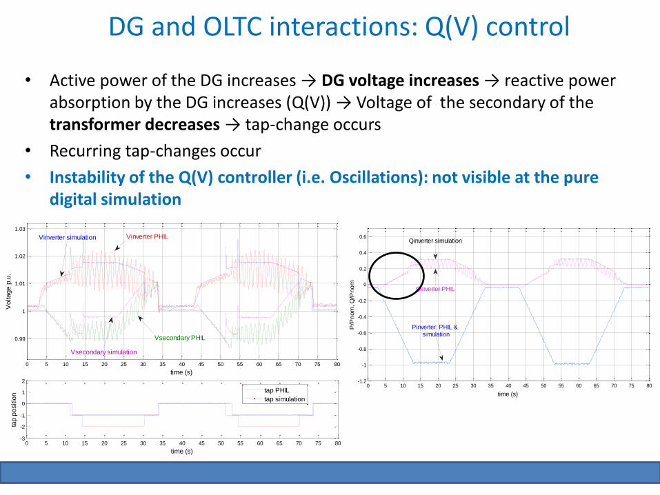
DG and OLTC interactions: Q(V) control
• Active power of the DG increases → DG voltage increases → reactive power absorption by the DG increases (Q(V)) → Voltage of the secondary of the transformer decreases → tap-change occurs
• Recurring tap-changes occur
• Instability of the Q(V) controller (i.e. Oscillations): not visible at the pure digital simulation
0 5 10 15 20 25 30 35 40 45 50 55 60 65 70 75 80
0.99
1
1.01
1.02
1.03
time (s)
Vo
lta
ge
p.u
.
0 5 10 15 20 25 30 35 40 45 50 55 60 65 70 75 80-3
-2
-1
0
1
2
time (s)
tap
po
sitio
n
tap PHIL
tap simulation
Vinverter simulation Vinverter PHIL
Vsecondary PHIL
Vsecondary simulation
Joint work with AIT
0 5 10 15 20 25 30 35 40 45 50 55 60 65 70 75 80-1.2
-1
-0.8
-0.6
-0.4
-0.2
0
0.2
0.4
0.6
time (s)
P/P
no
m, Q
/Pn
om
Pinverter: PHIL & simulation
Qinverter simulation
Qinverter PHIL

DG and OLTC interactions: Q(V) control
• Voltage drop at the HV network
• Similarly, the oscillations are not shown at the pure-digital simulation
0 1 2 3 4 5 6 7 8 9 10 11 12 13 14 15
0.95
0.96
0.97
0.98
0.99
1
1.01
1.02
1.03
1.04
time (s)
Vo
lta
ge
p.u
.
0 1 2 3 4 5 6 7 8 9 10 11 12 13 14 15-5
-4
-3
-2
-1
0
1
time (s)
tap
po
sitio
n tap PHIL
tap simulation
Vsecondary simulation Vsecondary PHIL
Vinverter simulation Vinverter PHIL
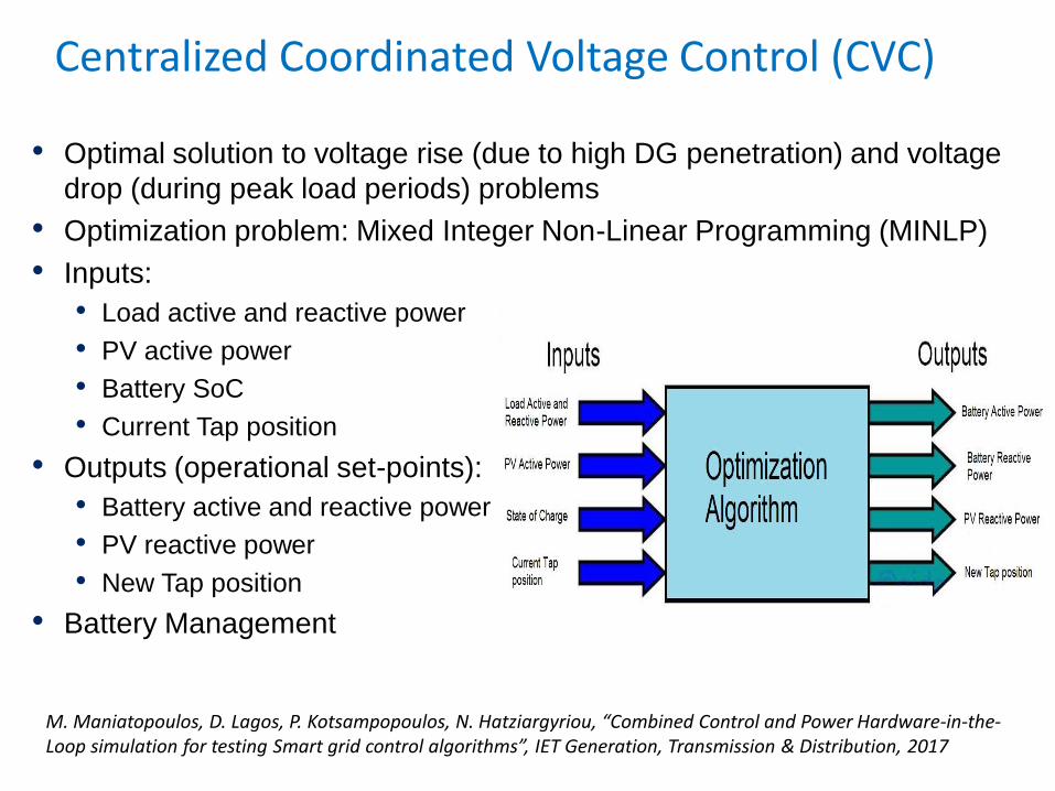
Centralized Coordinated Voltage Control (CVC)
• Optimal solution to voltage rise (due to high DG penetration) and voltage
drop (during peak load periods) problems
• Optimization problem: Mixed Integer Non-Linear Programming (MINLP)
• Inputs:
• Load active and reactive power
• PV active power
• Battery SoC
• Current Tap position
• Outputs (operational set-points):
• Battery active and reactive power
• PV reactive power
• New Tap position
• Battery Management
M. Maniatopoulos, D. Lagos, P. Kotsampopoulos, N. Hatziargyriou, “Combined Control and Power Hardware-in-the-Loop simulation for testing Smart grid control algorithms”, IET Generation, Transmission & Distribution, 2017

Coordinated Voltage Control – Optimization Problem Formulation
Constraints:
Bounds: Equalities:Inequalities:
_ _newtap Tap reference Tap changes

Rest of Power System
Supervisory Controller testing: Proposed testing chain of Smart Grid control algorithms
16

CVC validation: Laboratory Setup
The CVC algorithm was tested in pure simulation, CHIL and finally combined CHIL
and PHIL.
The combined CHIL and PHIL setup also provided:
o Insight on communication issues between the controller and the real
hardware
o Validation of the CVC with real power hardware behaviour
Combined CHIL and PHIL testing

CVC Results CHIL & PHIL simulation
Voltage of all nodes without voltage control Voltage of all nodes with CVC
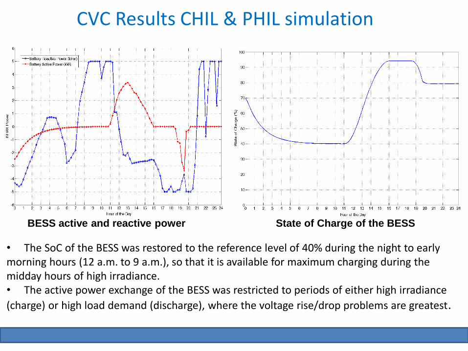
State of Charge of the BESSBESS active and reactive power
• The SoC of the BESS was restored to the reference level of 40% during the night to early morning hours (12 a.m. to 9 a.m.), so that it is available for maximum charging during the midday hours of high irradiance. • The active power exchange of the BESS was restricted to periods of either high irradiance
(charge) or high load demand (discharge), where the voltage rise/drop problems are greatest.
CVC Results CHIL & PHIL simulation

Tap Change operations of OLTC PV reactive power exchanges
0 1 2 3 4 5 6 7 8 9 10 11 12 13 14 15 16 17 18 19 20 21 22 23 24-20
-15
-10
-5
0
5
10
15
20
PV
R
eactiv
e P
ow
er (kV
Ar)
Hour of the Day
PV#1 Reactive Power
PV#2 Reactive Power
PV#3 Reactive Power
PV#4 Reactive Power
• The PV inverters contributed to voltage control by either absorbing (during hours of high irradiance to reduce the voltages) or generating (when an increase of the voltage is required) reactive power.
CVC Results CHIL & PHIL simulation

Remote real-time simulation via OPSim
OPSim tool: developed by Fraunhofer IEE
Interconnect two geographically distributed
simulators via the co-simulation environment
OPSim to assess delay impact on Real-Time
Simulation and to understand the boundaries
in the co-simulation environment OPSim.
Determine a holistic performance of a
Coordinated Voltage Control (CVC)
algorithm.
Joint work with Fraunhofer IEE
J. Montoya, R. Brandl, M. Vogt, F. Marten, A. Fabian, M. Maniatopoulos, “Asynchronous Integration of a Real-Time Simulator to a Geographically Distributed Controller through a Co-Simulation Environment”, IECON 2018

Remote real-time simulation: Test results
Bus Voltages OLTC - Tap Position
Joint work with Fraunhofer IEE
Conclusions
• Voltage rise due to DG integration is and will be a “hot topic” for the DSOs
• The flexibility of DER can be used to support the voltage
• HIL is a system-level testing method that proves to be beneficial for testing voltage control approaches in realistic and flexible conditions
• The PHIL tests of local voltage control revealed oscillations that were not visible in pure digital simulation
• The coordinated voltage control scheme was tested effectively in realistic conditions using the combined CHIL and PHIL environment
• A testing chain for system controllers (DMS/EMS) was proposed: combined CHIL and PHIL approach is more realistic.
• Remote real-time simulation test: the delays can impact the operation of the control algorithm