voltage influence on typical protection and controls for ... influence on protection... · red book...
TRANSCRIPT

1
Voltage Influence on Typical Protection and Controls for Motors, Power Electronics, and Other Common Loads
John Kueck
February 11, 2011
Prepared for: Western Electricity Coordinating Council
155 North 400 West, Suite 200 Salt Lake City, UT 84103

2
Table of Contents
Introduction I. Voltage Sensitive Equipment - Specific Guidance by Equipment Type 1. Example Discussion - Personal Computer 2. Programmable Logic Controllers 3. Adjustable Speed Drives 4. Motors a. Torque as a Function of Voltage b. High Efficiency Motors c. Stall d. Motor Protection 5. Contactors, Solenoids 6. Lamps 7. Ice Cube Relays - The Achilles Heel 8. Large Motor Contactors 9. Large Air Conditioners II. Conventional (Historic) Equipment Voltage Practice 1. Industrial and commercial per IEEE 493, Gold Book, Power Systems Reliability 2. IEEE Survey Showing Wide Variation in Service Loss Duration 3. Voltage Tolerance Limits, ANSI A and B 4. IEEE 1346 - Withdrawn Drop Out Points 5. Load Model Based on Field Data in Japan III. Recent Studies 1. Effect of voltage pre dip, point on wave and dip speed 2. Three phase dip 3. Voltage drop at residence 4. The Emerson Comfort Alert and Secure Start IV. Conclusions Bibliography
3
Introduction This report was written in a style that is to the point and avoids lengthy discussion. To assess the influence of voltage on typical protection and controls, a literature review of industry standards and other technical publications was performed. The most commonly used set of standards for equipment protection is the IEEE Colored Book Series and other key references as follows:
Buff Book IEEE Std 242-2001 Protection and Coordination of Industrial and Commercial Power Systems
Gray Book IEEE Std 241-1990 Electric Power Systems in Commercial Buildings Red Book IEEE Std 141-1993 Electric Power Distribution for Industrial Plants Gold Book IEEE Std 493-2007 Design of Reliable Industrial and Commercial Power
Systems Blue Book IEEE Std 1015-2006 Applying Low Voltage Circuit Breakers Used in
Industrial and Commercial Power Systems The National Electrical Code (NEC, 2008)
This report covers all load from 120 volts to 13.8 kV, but the above standards provide little guidance on the suggested setpoint for undervoltage trip for various types of equipment, especially for equipment under 600 volts, and there is significant latitude allowed to the designer. It is generally believed that at least one half of the total electric load is comprised by motors 480 volts and below and 200 Hp and below. Even if there were detailed standards for under voltage protection for these motors, there really is no requirement that the designer rigorously follow the standards. Also, there are relatively few equipment types for which under voltage protection is specified. There are a number of standards for voltage sag tolerance of equipment, and they seem to be constantly changing. Some of them are:
IEC 61000-4-34 provides testing and measurement techniques for voltage dips, short interruptions and voltage variations, and immunity tests for equipment with input current more than 16 A per phase.
SEMI F47 sets out the required voltage sag tolerance for semiconductor fabrication equipment
IEEE Standard 1346 (now Withdrawn) provided a recommended practice for analysis of voltage sag compatibility
CBEMA or ITIC Curve (Information Technology Industry Council) CIGRE 412, Voltage Dip Immunity of Equipment and Installations
The actual dropout point of much control and protective equipment probably depends more on the drop out voltage of relays and contactors, especially the ubiquitous ice cube relay. This issue is discussed in Section I.7 and in the references.

4
I. Voltage Sensitive Equipment - Specific Guidance by Equipment Type 1. Example Discussion - Personal Computer - To Introduce the Issues The best source for information on a specific device is the manufacturer. Any representation of voltage sag immunity for a particular equipment type is really just a generalization. EPRI has performed testing on various equipment types. Typically, in conventional voltage sag tolerance curves, the effect of phase shift, rate of change, point of initiation and other factors were not considered. The test sag was usually switched in at the voltage zero crossing point. The point of initiation, phase shift and other factors may have an influence on the equipment's ability to ride through the sag. Voltage sag tolerance levels seem to be constantly changing. For illustration, the following is an example of a personal computer voltage sag susceptibility curve from (IEEE_Std_1346_Rec_Practice_for_Evaluating_Electric_Power_System_Compatibility_with_Electronic_Process_Equipment, 1998) which has now been withdrawn. (IEEE_Std_493_Design_of_Reliable_Industrial..._Gold_Book, 2007) states that susceptibilities of various equipment types are known to differ significantly from the ITI/CBEMA levels. In this report, we will attempt to provide the latest available information.
It can be seen from the above figure that voltage tolerance for personal computers ranges from 50 to 80% voltage. This is actually a fairly typical set of tolerance curves. In addition to these

5
curves, (CIGRE_Voltage_Dip_Immunity_of_Equipment_and_Installations, 2010) lists a number of influential parameters that should be considered because of the impact they can have on voltage tolerance. These influential parameters include:
Pre dip supply voltage, voltage distortion, etc. Dip shape (rate of change), dip type, point on wave of dip initiation, phase shift, etc. Presence of other equipment in parallel feeders.
These influential parameters and their effect will be discussed further in Section III.1. 2. Programmable Logic Controllers - Latest Available Data Programmable logic controllers (PLCs) are used to control a wide range of industrial processes. A malfunction in a PLC could result in the entire process tripping or unsafe process condition. (CIGRE_Voltage_Dip_Immunity_of_Equipment_and_Installations, 2010) There is a wide range in the tolerance level of PLCs. Those used for critical or high risk applications are usually much more immune to dips. A PLC typically includes a power supply, a CPU and I/O modules. The power supply is usually a switched mode power supply to provide DC power to the CPU and I/O modules. Because of the failure consequences, most PLCs have protection that monitors the AC input voltage or the DC voltage. PLCs that monitor the AC input voltage may trip at 75% voltage for one cycle. On the other hand, the PLC may be equipped with DC bus capacitors and may tolerate 50% voltage for one half second. The I/O modules may be DC or AC. AC modules may react quickly and cause a shutdown in one cycle at 80% voltage. DC modules may survive a 50% voltage sag indefinitely.
6
3. Adjustable Speed Drives For ASDs, voltage threshold values range from 50-60% to 80-90% of rated voltage for magnitude, and from 1/2 cycle up to 5 cycles for duration. (Djokic, 2005) Lower values of pre sag voltage or increased motor mechanical loading will result in increased voltage sensitivity. A reduction of motor mechanical load will improve the drive voltage tolerance for both the allowable time and voltage level. In general, testing has shown that different points on wave of sag initiation and different phase shifts during the sag do not have an impact on three phase drive response to sags. This is because the drive is powered by a three phase rectifier; these rectifiers typically are three phase full bridge diode controlled rectifiers and are not affected by the point of initiation or phase shift. There are exceptions to this, however, because of susceptibilities in control circuits, and "The behavior of certain ASD's is influenced by phase shift and/or point on wave of sag initiation … " (Djokic, 2005) The ASD's own undervoltage protection is triggered after the dc link capacitor discharges and the dc link voltage drops below the minimum voltage. See figure below. This protection is triggered by interruptions and deep sags. The ASD's overcurrent protection is triggered by either by increased current drawn during the sag or high inrush current drawn immediately after voltage recovery to recharge the dc link capacitor. The trip level is usually from 120% to 170% of rated drive current. If two phases of voltage are near rated magnitude, the capacitor can still
7
be charged and one tested drive would not trip with one phase at zero if the other two phases were normal. An important protection issue highlighted during testing (Djokic, 2005) was missing phase protection; the drive may have continued to operate with the missing phase.
4. Motors a. Torque as a function of voltage The torque of an induction motor is proportional to the square of the terminal voltage. A motor operated at 70% rated voltage will produce about 49% of its rated torque. This means that the pump or fan will slow down to match the new motor torque output. Also, when there is a voltage dip, the motor will be decelerated by the effect of regenerating back into the bus. The rotational inertia of the pump or fan will keep the motor spinning, while the regeneration will act to slow it. The effect of regeneration to slow the motor depends on the stiffness of the system. A stiff system will apply more decelerating torque. When a motor is slowed all the way to stall by reduced voltage, the time required to stall the motor depends on the 'stiffness" of the system. Tests by SCE showed that a stiff system can stop an induction motor with very low inertia in one

8
cycle where a weak system stops the motor in 18 cycles. (Chinn) This is not to say that a "weak" system is to be preferred. With a stiff system, a motor is less likely to stall, and will be more easily started because the motor terminal voltage and thus torque will be higher during starting. On those rare occasions when the voltage does drop in a stiff system, however, the motor will be more rapidly decelerated by the effect of regeneration because the terminal voltage will be held lower. As a study tool, a range of motor application scenarios could be analyzed with various voltages, loads, sizes, protection and control systems. These scenarios could analyze the pre dip voltage, restart, overload settings, phase jump, system stiffness, load torque curves, etc. etc. The problem with analyzing a large number of scenarios though is, how do we deduce what relationship this large group of scenarios has to reality? One approach may be to develop representative motor/load models for various locations. Motor application scenarios and challenges are discussed below. Typically, the torque reduction with voltage usually is only a problem at motor starting. Large motors powering large centrifugal pumps or fans have to be specified to provide enough torque to start the pump or fan (accelerating the inertia) while the motor is being started and is drawing six times rated current at a poor power factor. While the motor is starting, voltage drop is at the worst case, and torque is impacted by the square of this drop. Large motors are often built with special rotor bar designs so that they can provide adequate torque on starting. The figure below shows a motor speed torque curve for a typical large induction motor at rated voltage and 75% voltage. It can be seen that at 75% voltage the motor torque will overcome the load inertia, but will probably fail to accelerate it.

9
NEMA Design motors are specified by a NEMA design letter, A through D, which specifies the motor speed - torque relationship as in the figure below. By far the most common is Design B, which is used for pumps, fans and other typical industrial loads. Design D is a high locked rotor torque design used for loads such as valve actuators which require high starting torque. Typically, the torque curve is reduced by the square of the per unit voltage for reduced voltage applications. Note that the Design B curve in the NEMA figure below does not exactly match the speed torque curve in the figure above. This is because the NEMA MG1 standard only applies to motors up to 500 HP, and it only specifies the locked rotor torque and breakdown torque, not the points in between. It is important for pumping and fan system designers to understand the load torque curve of their system and ensure the motor has adequate pull up torque to start the load under the anticipated voltage conditions. This is discussed further below under b. Torque Delivered by High Efficiency Motors below.

10
Typical centrifugal fans and pump systems impose a load torque that is the sum of the load of the centrifugal pump or fan, and the load of the frictional loss and head of the system. Starting the pump or fan with the discharge damper or valve closed will remove the system component and reduce the needed starting torque. For this reason, large pumping system motors are sometimes started with the pump discharge valve closed. The valve must be opened quickly though as the temperature of the spinning water will increase and cause problems when the water reaches the boiling point. For an example of a starting process, a large water pumping utility uses this procedure for starting large (20,000 Hp) vertical, centrifugal pumps:
First, the pump discharge valve is closed. Second, compressed air is used to blow the water out of the pump so the pump can be
started dry (The pump itself may be 100 feet tall.) The dry pump is started. (The motor is started across the line.) After the pump is started and has come up to speed, water is allowed into the pump and
the pump is filled and the water is spinning in the pump. Finally, the discharge valve is slowly opened and water begins to pump through the
system. The entire starting process may take 5 minutes.
Representative speed torque curves for various types of loads are shown in the following figure.

11
Speed Torque Curves for Representative Loads When operating at reduced voltage, the motor torque drops and the speed will drop. As speed drops a little, the load torque drops off quickly (see figure below) and the motor will reach a new operating point when the reduced motor torque equals the new system load torque. The time it takes for the motor to reach this new steady state speed depends on the total motor - load system inertia, the applied torque and the stiffness of the system.

12
Motor Speed Change at Reduced Voltage With typical voltage sags lasting only a few cycles, however, the motor will probably not slow down during the sag to the new steady state speed because the motor will be reaccelerated when the voltage recovers. Scroll compressors used in high efficiency air conditioners are exceptions to the above discussion. Scroll compressors have very low inertias and thus can be decelerated very quickly and even stopped, or stalled during voltage sags. This is discussed further in Sections B and C below. .. In (Chinn) residential air conditioning motors are represented as a typical induction motor load until the voltage dips below 0.6 pu, they then transition immediately to a fixed constant current load with a power factor of 0.88. After 2.5 seconds of stall they are tripped on overcurrent. Synchronous motors are usually used in large, low speed applications like water pumps. Synchronous motors can act as a source or sink of reactive power by controlling their field excitation. An overexcited synchronous motor supplies reactive power and is sometimes called a Synchronous Condensor, or in other words, a synchronous capacitor. When synchronous motors are driving a load, their field excitation is usually controlled so that they are drawing a power factor of 1.0 and sometimes controlled to provide a leading Power Factor. In theory, synchronous motors which have the kVA capacity could be controlled so that they support voltage during transients by following a Volt Var schedule, but this is rarely done in practice.

13
Synchronous motors are typically started with damper windings and behave very much like induction motors when they start, drawing as much as 6 to 8 times their normal running current. In the figure below, when the motor is operating at 100% PF, the full load current is at a minimum, about 40 amps, and the field amps are at about 12 amps.
Synchronous Motor Running at Full Load Synchronous motors run without slip and thus do not have torque curves like induction motors; if the "pull out" torque is exceeded the motor will pull out of step. The torque varies with the square of the applied field voltage. Synchronous motors are usually equipped with loss of excitation relays to protect against damage, heating, voltage drops and unstable operation after loss of excitation. Synchronous motors are expensive and are often equipped with protection for: damper windings, excitation voltage, harmonic currents, incomplete starting sequence, locked rotor, overvoltage, phase unbalance, pullout, rotor over temperature, and voltage sags. Synchronous motors with proper controls can be made to ride through voltage sags for several cycles, but may be damaged by reclosure or continuing low voltage at the motor terminals. (IEEE_Std_242_Recommended_Practice..._Buff_Book, 2001)

14
b. Torque Delivered by High Efficiency Motors To gain an understanding of how high efficiency motors differ from normal general purpose NEMA Design B, we can look at the characteristics of the NEMA Design E motor (now expired) compared to the general purpose motor:
The minimum allowable locked-rotor torque, breakdown torque and pull up torque for specific hp ratings are lower than NEMA allows for general purpose Design B motors, particularly in the smaller sizes. A Design E motor may not be able to start the same pump or fan, especially at reduced voltage.
A Design E motor, however, can draw a locked rotor current as much as 55% higher than that of a conservatively built Design B (General Purpose) motor with the same horsepower because of the increased cross sectional area of the rotor bar.
Thus in the case of high efficiency motors, in general, we may have less starting and pull up torque and higher locked rotor current. The motor designer tries to reduce the motor losses by designing a low resistance rotor bar when the motor is running at full load. However, at locked rotor, a high resistance bar is desired to produce higher torque. At full load speed, the entire cross section of the rotor bar carries current; at locked rotor, the current in the bar crowds to the top of the bar. Motor designers sometimes narrow the slots at the top of the bar to develop more locked rotor torque. The more locked rotor current that is allowed, the less material that has to be removed, and the higher the efficiency. Thus the higher efficiency comes at the cost of less torque and higher locked rotor current. (Daugherty, 1997) This reduction in torque is not necessarily the case with every high efficiency motor, the motor designer can design a motor with higher efficiency and maintain the same level of torque and current, but this type of motor is a "premium" motor that is more expensive and would probably only be found in special applications such as in refineries or other industrial applications where an engineer has elected to specify a premium motor. In some areas, premium high efficiency motors are being used to replace synchronous motors in pumping applications up to 5,000 to 6,000 Hp. In general, these motors should be designed to a carefully specified speed torque curve that is capable of starting and running the pump under anticipated voltage conditions. Induction motors equipped with adjustable speed drives are also replacing synchronous motors in applications where precise speed and torque control are needed; extremely accurate speed, torque and even rotor position can be supplied with adjustable speed drives. c. Stall Large three phase motors have undervoltage relays which can remove a stalled unit within cycles. Motors of 25 HP and less typically do not have undervoltage protection. Thermal relays

15
used with smaller motors (25 Hp and less) have characteristics depending on the type of motor they protect. High torque, momentary duty motors may have stall protection set as fast as five seconds. The author has had experience with an induction motor that was could be held in a stalled condition for several minutes with little temperature rise. Valve actuator motors (high torque, momentary types) may be seriously damaged in as little as 10 seconds of locked rotor current. In general, the fastest the vast majority of motors would trip on thermal overload may be two to three seconds, and the longest time may be two to three minutes. As noted below, during voltage sags to below 75%, the contactor may drop out anyway. This is discussed further in Section 5. If the contactor drops out, the motor typically will not restart when the voltage is restored. d. Motor Protection The IEEE Buff Book (IEEE_Std_242_Recommended_Practice..._Buff_Book, 2001) has a Section 10.3.2.1 Motor Protection, Undervoltage which states that undervoltage protection may be used for:
To prevent a motor from automatically restarting when voltage returns following an interruption using either controls or an undervoltage relay.
To avoid excessive inrush to the total motor load on the power system with a corresponding voltage sag following a voltage dip or interruption.
To avoid reaccelerating motors before their fields collapse. Section 10.3.2.2 describes time delay undervoltage protection which should be used on motors important to continuity of service to prevent unnecessary tripping. The standard also states that the time delay should not be set to actuate before fault detecting relays have had a chance to clear faults. However, the standard points out that time delay undervoltage protection will often not be satisfactory. Magnetically held contactors may drop out before the undervoltage protection. Systems with fast automatic transfer or reclosing may not coordinate with the undervoltage relay. A problem could arise in having to restart a total motor load having time delay undervoltage protection with excessive inrush current and voltage drop after an interruption. Section 10.4.4 describes under voltage relays for low voltage motor protection (1,000 volts and below.) This section states that the designer usually sets the device at 85% of the line voltage and a time delay to trip and a time delay to restart. It is this author's experience, however, that low voltage motor protection is rarely used for motors at 1,000 volts and below. Section 10.4.4 states that low voltage protection can be used for cases such as low voltage operation causing temperature rise or automatic reclosing where the motor may be switched back in before the field has collapsed. For large motors, the IEEE Red Book (IEEE_Standard_141_Red_Book, 1993) states in Section 5.6.3.1 motor protection may include:
Internal fault protection - either overcurrent relays or percentage differential relays; sometimes ground fault protection is provided using a zero sequence approach.

16
Sustained overloads and locked rotor - Conventional over current relays may provide too much margin between the motor thermal capability curve and the relay operating time characteristic. Overcurrent relays do, however, provide excellent locked rotor and short circuit protection. Thermal relays will give adequate protection for light and medium overloads.
Under voltage - Large motors and medium voltage motors should have separate undervoltage protection.
Phase unbalance or phase reversal protection - should be applied in all cases where such conditions are likely to exist.
For small three phase motors (IEEE_Standard_141_Red_Book, 1993) Section 5.6.3.2 states that motor protection should include:
A magnetic circuit breaker or fuses for overcurrent protection and three thermal overload relays for running overcurrent protection.
The National Electrical Code (NEC, 2008) Article 430.52 requires that continuous duty motors over one horsepower shall be protected against overload by one of the following means:
A separate overload device that is responsive to motor current. This device is selected to trip at no more than 115% to 125% of the motor nameplate full load current rating.
A thermal protector integral with the motor. The trip current of the thermally protected motor shall not exceed 170% (motors with FLA 9 amps and less) 156% (FLA 9.1 to 20) and 140% (FLA greater than 20).
A protective device integral with the motor if the motor is part of an approved assembly not normally subjected to overloads.
For motors over 1500 Hp, a temperature sensitive protective device embedded in the motor windings.
Thus the NEC does not require undervoltage protection for motors for motors up to 600 volts. If the NEC does not require it, it will only be provided in unique circumstances where it was deemed necessary. Industrial motor systems account for approximately twenty three per cent of all electricity consumed according to the DOE, and large motors, i.e. those over 200 horsepower, account for only one percent of the motors in the entire manufacturing inventory, but use 45 percent of the energy use. However, under voltage protection is typically an accessory on combination motor starters. In some cases of extremely critical motors, such as valve actuators for safety related valves in nuclear generating stations, guidance has sometimes been provided to set the thermal overload in a manner that provides every opportunity for the motor to perform its critical function. The thermal overloads were sometimes set quite high by the protection designer. These unique, high torque motors, however, could actually be degraded by carrying locked rotor current for as little as 10 seconds. This degradation is internal to the motor and could easily go unnoticed. (Kueck,

17
1988) It is thus essential that the protection designer understand the capabilities of the motor, the torque requirements of the driven system, and the range of the motor terminal voltage. 5. Contactors, Solenoids Contactors and solenoids have a wide range of voltage tolerance. They range in sensitivity from AC contactors dropping out at 75% voltage in 10 msec to DC holding in at 35% voltage indefinitely (CIGRE_Voltage_Dip_Immunity_of_Equipment_and_Installations, 2010) page 52. Contactors can be very sensitive to the point on the voltage sine wave where the dip is initiated. This is because the stronger the magnetic field at the instant of dip initiation, the better the contactor will ride through the dip. This is discussed further in Section III, Recent Studies. Some circuit breakers are suitable for motor starting duty and are used at voltages of 4.16 kV and higher when there is not a high degree of repetitive duty (motor starts) that need to be withstood. When there is a high number of motor starts, contactors are used. Contactors are available at voltages up to 13.8 kV.
6. Lamps Incandescent Incandescent filament lamps are quite tolerant to voltage sags, but the light output and lifetime are dramatically impacted by sustained voltage deviations. For example, at 105 volts, a 120V

18
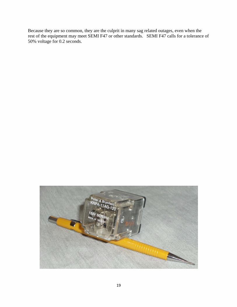
light bulb will produce 64% of its rated light and have 575% of its normal lifetime. At 130 volts, it will produce 132% of its rated light and have 34% of its normal lifetime. (IEEE_Standard_141_Red_Book, 1993) Section 3.5.4 Fluorescent Light output for fluorescent lamps with magnetic ballasts varies in roughly direct proportion to voltage. Light output for electronic ballasts may be more or less dependent on voltage. The life of fluorescent lamps is affected less by voltage variation than incandescent. The ballast itself is actually the voltage sensitive component. Thermal protection that is integral with the ballast is required for fluorescent luminaires installed indoors. (NEC Article 410.130) Fluorescent lamps will simply blink or stop illuminating if voltage drop lasts too long, and then restart after voltage sags. When fluorescent fixtures are turned on there is a momentary inrush of current. This inrush is 5 times greater than normal operating current for magnetic ballasts and can be as high as 40 times greater than normal operating current for electronic ballasts. This inrush is to charge the capacitor and lasts for one millisecond or less. The only protection concern is that when large numbers of fluorescent lamps are switched on, the circuit breaker may trip or even damage contacts due to the inrush. Fluorescent lamps may stop working anywhere between 80 and 40% voltage and in as little as 10 milliseconds. Some electronic ballasts may keep the light working at 40% indefinitely. 7. Ice Cube Relays - The Achilles Heel Ice cube relays are simple electromagnetic relays that stay energized to hold in contactors and other control equipment. They may drop out due to sags that do not impact other components in a control system, and thus cause a large motor or production line to shut down. Typically, when these relays drop out, there is no mechanical latch mechanism and the relay changes state until adequate voltage is restored to the relay. Ice cube relays can have an average dropout of 70% of nominal for a cycle or less. (Stephens,Mark_EPRI, 2010) Testing has shown that they can drop out in one quarter cycle at 30% voltage. The referenced report says that while many components have made improvements in their ability to ride through sags, AC ice cube relays have not. (The DC relays are much better.) These relays are ubiquitous in 120 volt control circuitry, for example:
Emergency stop circuits Door interlock circuits Air compressor starter controls Chiller controls Conveyor controls Oven controls PLC - Motor interface circuit ASD start circuit Vending machines
19
Because they are so common, they are the culprit in many sag related outages, even when the rest of the equipment may meet SEMI F47 or other standards. SEMI F47 calls for a tolerance of 50% voltage for 0.2 seconds.

20
Ice Cube Relay
Ice Cube Relay Pins
8. Large Motor Starter Contactors A contactor is needed when there is a high degree of repetitive duty (start -stops). Contactors are designed for more operations than a circuit breaker. When a contactor is used, it is used in series with a circuit breaker or fuses. Motor contactors are usually connected as single phase devices, even on three phase equipment. Motor starter contactors may open at 65 to 75% voltage in the case of 2300 or 4600 Volt motors and 55 to 65% in the case of 460 Volts and below. (Task_Force_on_Load_Representation, 1992) (p 477) As stated above, the contactor dropping out or control relays dropping out is really the only fast undervoltage protection that motors under 600 volts typically have. 9. Large Air Conditioners Large three phase air conditioning in industrial or commercial applications typically have undervoltage relays which trips in perhaps six cycles after the voltage drops below 0.6 pu. (Chinn) (p. 3)

21
II. Conventional (Historic) Equipment Voltage Practice 1. Industrial and commercial per IEEE 493, Gold Book, Power Systems Reliability The (IEEE_Std_493_Design_of_Reliable_Industrial..._Gold_Book, 2007) (p 141) suggests a philosophy of sag prediction, locating boundaries on the electrical system where specific sag magnitudes are possible, then estimating the fault frequency in the boundary. The sag durations are determined using the characteristics of the fault clearing equipment. Predicting fault frequency requires an accurate network model and reliability data for all the equipment in the neighborhood. The number of events vs. sag voltage in percent of nominal is a way to display likelihood to trip at various sites. To be complete, the effect of pre fault voltage should be considered. This is discussed more in Section III below. 2. The (IEEE_Std_493_Design_of_Reliable_Industrial..._Gold_Book, 2007) states that an interruption is the reduction of load point voltage to less than 10% of the nominal rms value. Yet, critical production equipment may cease to operate normally if the load point voltage drops below 80 to 85%. IEEE surveys have shown a wide variation in the minimum or critical service loss duration, i.e. the maximum length of time an interruption of electrical service will not stop plant production. The following table summarizes Critical Duration Service Loss results for 55 industrial plants. Critical Duration Service Loss is the maximum length of time an interruption of electrical service will not stop plant production.
25th percentile
median
75th percentile
Average plant outage time for
equipment failure between 1 and 10
cycle duration. 10 cycles 10 seconds 15 minutes 1.39 hours
3. Voltage Tolerance Limits
The voltage tolerance limits of (ANSI_C84.1, 2006) are based on NEMA Standard MG1, Motors and Generators. MG1 assists users in the selection and application of motors and generators. It contains practical information on motor performance and manufacture.
The same ANSI voltage tolerance limits are shown as the standard voltage profile for a low voltage regulated power distribution system in (IEEE_Standard_141_Red_Book, 1993) Table 3-2 as follows. Range A is normal utilization voltage. Range B voltages are those that result from practical design considerations and shall be limited in frequency and duration. Outside Range B protective devices may operate. The following are on a 120 volt base. Range A Range B Maximum allowable voltage 126 127 Voltage drop allowance for primary distribution line
9 13
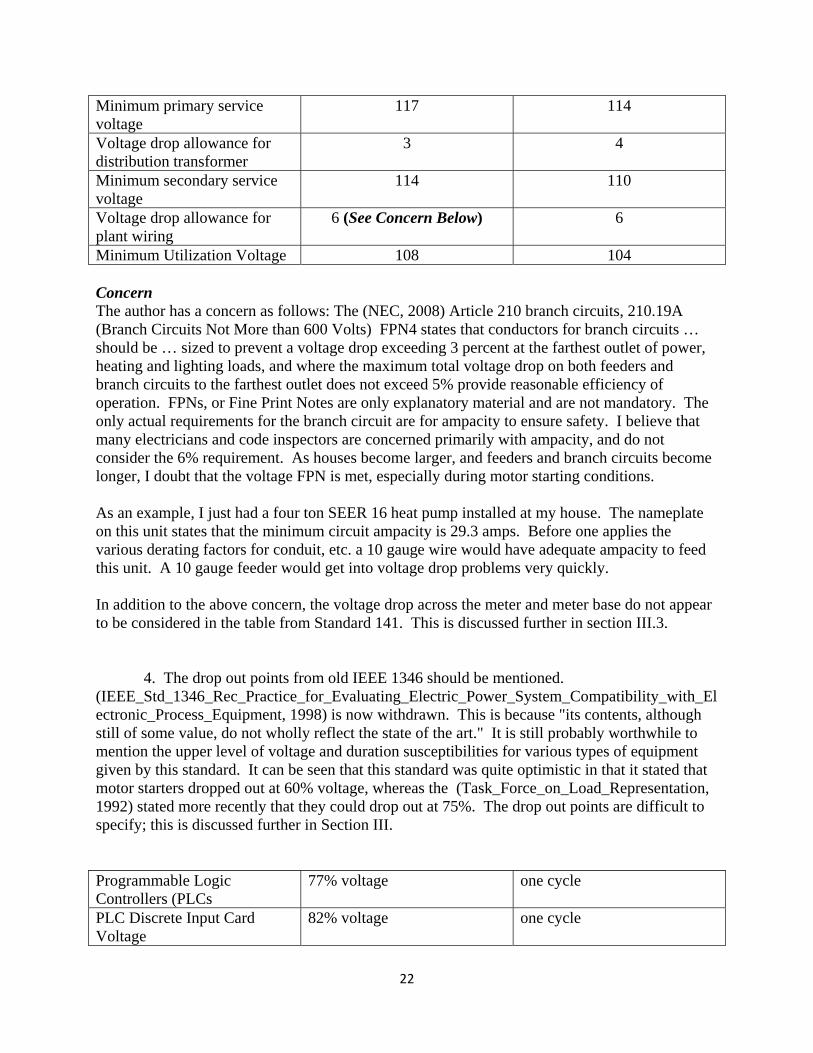
22
Minimum primary service voltage
117 114
Voltage drop allowance for distribution transformer
3 4
Minimum secondary service voltage
114 110
Voltage drop allowance for plant wiring
6 (See Concern Below) 6
Minimum Utilization Voltage 108 104 Concern The author has a concern as follows: The (NEC, 2008) Article 210 branch circuits, 210.19A (Branch Circuits Not More than 600 Volts) FPN4 states that conductors for branch circuits … should be … sized to prevent a voltage drop exceeding 3 percent at the farthest outlet of power, heating and lighting loads, and where the maximum total voltage drop on both feeders and branch circuits to the farthest outlet does not exceed 5% provide reasonable efficiency of operation. FPNs, or Fine Print Notes are only explanatory material and are not mandatory. The only actual requirements for the branch circuit are for ampacity to ensure safety. I believe that many electricians and code inspectors are concerned primarily with ampacity, and do not consider the 6% requirement. As houses become larger, and feeders and branch circuits become longer, I doubt that the voltage FPN is met, especially during motor starting conditions. As an example, I just had a four ton SEER 16 heat pump installed at my house. The nameplate on this unit states that the minimum circuit ampacity is 29.3 amps. Before one applies the various derating factors for conduit, etc. a 10 gauge wire would have adequate ampacity to feed this unit. A 10 gauge feeder would get into voltage drop problems very quickly. In addition to the above concern, the voltage drop across the meter and meter base do not appear to be considered in the table from Standard 141. This is discussed further in section III.3. 4. The drop out points from old IEEE 1346 should be mentioned. (IEEE_Std_1346_Rec_Practice_for_Evaluating_Electric_Power_System_Compatibility_with_Electronic_Process_Equipment, 1998) is now withdrawn. This is because "its contents, although still of some value, do not wholly reflect the state of the art." It is still probably worthwhile to mention the upper level of voltage and duration susceptibilities for various types of equipment given by this standard. It can be seen that this standard was quite optimistic in that it stated that motor starters dropped out at 60% voltage, whereas the (Task_Force_on_Load_Representation, 1992) stated more recently that they could drop out at 75%. The drop out points are difficult to specify; this is discussed further in Section III. Programmable Logic Controllers (PLCs
77% voltage one cycle
PLC Discrete Input Card Voltage
82% voltage one cycle

23
PWM Adjustable Speed Drive 82% voltage one cycle AC Relay 77% voltage one cycle Motor Starter Coil 60% voltage two cycles PC Power supply 80% voltage Three cycles 5. Load Model Based on Field Data in Japan A paper by K. Tomiyama et al, "Modeling of Load During and After System Faults Based on Actual Field Data" (Tomiyama, 2003) Section C, Load Drop, finds that "… Some of the tripped loads are not restored until after the voltage recovers… The lowest voltage affects the volume of load tripped during the fault. The load drop does not occur if the lowest voltage is higher than 0.85 pu. The load drop occurs if the lowest voltage becomes lower than 0.85 pu, and rapidly increases when the lowest voltage is around 0.6 pu. The load drop, however, saturates after that and does not increase over 30% ..."
Measured Data of Volume of Load Drop vs. Lowest Voltage During Sag (Tomiyama, 2003)

24
III. Recent Studies 1. Effect of voltage pre dip, point on wave and dip speed More recent studies have shown that in addition to the dip magnitude and duration there are a number of parameters which have a major impact the capability of a device to ride through an interruption. (CIGRE_Voltage_Dip_Immunity_of_Equipment_and_Installations, 2010) These parameters include:
Pre dip voltage magnitude and distortion of sine wave. Unbalance during dip for three phase devices, dip shape, and point on the sine wave
where the dip starts. Speed of recovery of dip. Source impedance (distribution transformer). Other equipment connected close by.
The point on the sine wave is important because of the energy stored in the magnetic circuit. The stronger the field when the dip begins, the more likely the contactor or relay will ride through the dip. Because of the lagging current drawn by the contactor coil, contactors are most sensitive to dips that begin at 90 degrees and least sensitive to dips that begin at zero crossing. See the figure below which is a representation of laboratory tests by CIGRE (CIGRE_Voltage_Dip_Immunity_of_Equipment_and_Installations, 2010) showed that dips initiated at 90 degrees may drop out a contactor in less than10 msec. Dips initiated at 0 degrees may not drop out the same contactor for 80 msec even at zero volts.
25
These same test findings have been confirmed by other institutions performing contactor ride through capability tests. (Mohamed, 2010) Because of the significant impact of these parameters, it is not accurate to represent the impact of dips with simple voltage tolerance curves. I suspect that this is the reason IEEE Standard 1346 (IEEE_Std_1346_Rec_Practice_for_Evaluating_Electric_Power_System_Compatibility_with_Electronic_Process_Equipment, 1998) has been withdrawn. 2. Three phase dip (CIGRE_Voltage_Dip_Immunity_of_Equipment_and_Installations, 2010) divides three phase voltage dips into three types as follows: i. A voltage drop mainly in one phase to ground voltage (Type 1) ii. A drop in magnitude in mainly one phase to phase voltage (Type 2) iii. A drop in magnitude that is equal for the three voltages (Type 3, least common case). The study concludes that compliance testing of three phase equipment should include each type of voltage dip because the different types can have different effects on various types of equipment. For example, an adjustable speed drive may still be able to charge the DC link capacitors with a type 1 dip, in fact, many drives are able to ride though any type 1 dip as mentioned above. (CIGRE_Voltage_Dip_Immunity_of_Equipment_and_Installations, 2010)

26
proposes five voltage dip immunity classes that consider the voltage dip type as well as the duration and magnitude. Point on wave, pre dip voltage and dip speed are not included in these suggested immunity classes presumably because, in spite of their significant impact, they would create too much complication. The vast majority of faults in the system are single phase to ground, but it is not reasonable to assume that a maximum of only 1/3 of the load any feeder will be subject to dropping during the single phase fault even if there is a fairly balanced distribution of load among the three phases. This is because motors, transformers and other three phase equipment will still be tripped from negative sequence voltage relays, phase unbalance protection, ground fault protection and differential protection that may actuate as a result of the single phase to ground fault. 3. Voltage drop at the residence. As mentioned above, the National Electrical Code defines the minimum ampacity of conductors to ensure that there is no danger of overheating and fire. The NEC does not provide specifications for voltage drop but only states that "Conductors for branch circuits …should be … sized to prevent a voltage drop of 3% at the farthest outlet … and … the maximum total voltage drop on both feeders and branch circuits to the farthest outlet does not exceed 5 percent provide reasonable efficiency of operation." The NEC provides sample voltage drop calculations in a commentary following 215.2(A)(3). However, voltage drop calculations are not required and are probably rarely performed. As homes become larger, and subpanels more common, I believe it is likely that voltage drop may exceed the total of 5%. Article 440 of the NEC, Air Conditioning and Refrigerating Equipment, discusses only determining correct compressor feeder ampacity based on the motor current and does not consider voltage drop. If a house is under a Conservation Voltage Reduction program, and the target voltage at the meter is 114 volts, with the five percent guideline, the motor terminal voltage will be 107 volts before a dip. This leaves the motor much more susceptible to stalling because, as discussed above, its initial speed and torque will be lower. If the electrician did not do a voltage drop calculation, and perhaps used a long wire as a feeder, the voltage drop may be more than 5% and the air conditioner will be even more susceptible to stalling. In addition, the voltage drop across the meter is unknown and assumed to be zero. The meter base is covered by one standards organization and the meter itself by another organization. I don't know of one entity that specifies the maximum resistance across the socket, stabs and meter. A total resistance of 0.25 ohms would provide a 5 volt drop for a current flow of 20 amps. Pre dip voltage is an influential parameter in determining equipment immunity during voltage dips. An additional small percentage of predip voltage could have a significant influence on equipment response to the dip. 4. The Emerson Comfort Alert and Secure Start

27
Emerson now sells a Comfort Alert diagnostics module which installs in the box of the outdoor unit. The module detects the cause of electrical and system related failures and flashes an alert code to guide the service technician. The Comfort Alert flashes a code when the control circuit voltage is less than 17 volts. This is equivalent to 71% voltage. The Secure Start module monitors supply voltage while the compressor is running and protects against low voltage or locked rotor. It also reduces voltage during start and gives a soft start. IV. Conclusions Voltage tolerance curves are available for a wide range of equipment, but recent work has shown that the actual drop out voltage may depend more on the point of the wave where the dip begins than the dip magnitude and duration. Another significant factor for three phase equipment is the type of three phase fault and the phase shift that occurs during the fault. In general, it appears that contactors, relays, adjustable speed drives, large air conditioners and large motor protection will drop out at 60% to 75% voltage, but there is a wide variation in tolerance level. Newer equipment with DC power supplies can remain operable, in some cases, at continuous voltages as low as 50%. High efficiency motors produce less torque than their conventional ancestors, and are more prone to stall and not to restart as a result of a dip. Undervoltage protection is typically not provided on motors under 600 volts, but it is provided, in a sense, by contactors and control relays which may drop out at 70% voltage. The real "Achilles Heel" of load susceptibility is probably the ice cube relay. These relays are used in a wide range of equipment. They will drop out between 70 and 60 percent voltage in a cycle or less. Historic voltage assessment practice, which relied on only two parameters - dip magnitude and duration, may be out dated, and more recent works are emphasizing several other parameters, such as point on wave and phase displacement. The author has a concern with conventional voltage tolerance limits because they may not adequately consider voltage drop in branch circuits and voltage drop across the meter and meter base. Conservation voltage reduction programs, combined with long branch circuits in the house, will certainly contribute to initial voltages being near or perhaps below the minimum utilization voltage. This low starting voltage contributes significantly to the likelihood of motor stall during a fault. As a study tool, a range of motor application scenarios could be analyzed with various voltages, loads, sizes, protection and control systems. These scenarios could analyze the pre dip voltage, restart, overload settings, phase jump, system stiffness, load torque curves, etc. etc. The problem

28
with analyzing a large number of scenarios though is, how do we deduce what relationship this large group of scenarios has to reality? One approach may be to develop representative motor/load models for various locations.

29
Bibliography ANSI_C84.1. (2006). Electric Power Systems and Equipment ‐ Voltage Ratings (60 Hertz). American National Standards Institute. Chinn, G. L. Modeling Stalled Induction Motors. CIGRE_Voltage_Dip_Immunity_of_Equipment_and_Installations. (2010). Voltage Dip Immunity of Equipment and Installations C4.110. Daugherty, R. (1997). NEMA Design E Motors and Controls ‐ What's It All About. IEEE. Djokic, S. (2005). Sensitivity of AC Adjustable Speed Drives to Voltage Sags and Interruptions. IEEE. IEEE_Standard_141_Red_Book. (1993). IEEE Recommended Practice for Electric Power Distribution for Industrial Plants. IEEE Standard 141, The Red Book . IEEE. IEEE_Std_1346_Rec_Practice_for_Evaluating_Electric_Power_System_Compatibility_with_Electronic_Process_Equipment. (1998). IEEE Standard 1346. IEEE ‐ Now Withdrawn. IEEE_Std_242_Recommended_Practice..._Buff_Book. (2001). Recommended Practice for Protection and Coordination of Industrial and Commercial Power Systems. IEEE. IEEE_Std_493_Design_of_Reliable_Industrial..._Gold_Book. (2007). Std_493_2007_Design_of_Reliable_Industrial_and_Commercial_Power_Systems. IEEE. Kueck, J. D. (1988). An Investigation of Magnesium Rotors in Motor Operated Valve Actuators. IEEE Transactions on Energy Conversion , 40‐43. Mohamed, A. (2010). Experimental Investigation of AC Contactor Ride Through Capability During Voltage Sag. 9th International Conference on Environment and Electrical Engineering (EEEIC). Prague. NEC. (2008). National Electrical Code. National Fire Protection Association. Stephens,Mark_EPRI. (2010). AC Ice Cube Relays for Improved Power Quality. Retrieved from Electric Energy Online: electricenergyonline.com Task_Force_on_Load_Representation. (1992). Load Representation for Dynamic Performance Analysis. IEEE. Tomiyama. (2003). Modeling of Load During and After System Faults Based on Actual Field Data. IEEE Power Engineering Society General Meeting .