volume 3 operations and safeworking part 2: route standards
TRANSCRIPT

…back to Contents
Need help using this CD? Click here.
CODE OF PRACTICE FOR THE
DEFINED INTERSTATE RAIL NETWORK
VOLUME 3
OPERATIONS AND SAFEWORKING Part 2: Route Standards
This Code was prepared by DOTARS in 2002. ARTC adopted this Code but advises that it has not been maintained by DOTARS (or successor organisations) and that tables 1 to 7 are out or date. For up to date information for these tables refer to the ARTC Route Access Standard (RAS). This note on applicability was approved by GM Technical Standards and Environment on 14 March 2013.
MAY 2002

IMPORTANT NOTICE AND DISCLAIMER
This Code of Practice has been drafted for use by rail operators and the rail industry on the Defined Interstate Rail Network as defined in this Code in conjunction with, or to supplement, the existing codes of the rail organisations.
The Commonwealth and all persons acting for the Commonwealth in preparing the Code disclaim any liability or responsibility to any person for any consequences arising directly or indirectly from the use by the rail industry or rail organisations of the Code in whole or in part, and whether or not in conjunction with, as a supplement to, the codes which the rail industry currently use.
Users of the Code should be aware that, while using the Code, they must also comply with any relevant Commonwealth, State or Territory legislation relevant to their operations. Adherence to the Code does not replace or exclude the application of such legislative requirements. Users are responsible for making their own enquiries in relation to the application of legislation, and the framers of the Code accept no responsibility in this regard.
Adherence to the Code does not necessarily ensure compliance with any relevant national standards and other codes of practice. Users are responsible for making their own enquiries in relation to compliance with national standards and other codes of practice.
While all reasonable care has been taken in the preparation of this Code, it is provided to rail operators without any legal liability on the part of the Commonwealth and the Commonwealth [publisher, authors, consultants and editors each] takes no responsibility for loss suffered by any person resulting in any way from the use of, or reliance on, this publication. Responsibility rests with the rail organisation to ensure that all aspects of the Code are safe.
Commonwealth of Australia

Code of Practice for the Defined Interstate Rail Network
This Code does not supersede previous rules and instructions until the Code (in full or in part) is adopted and officially implemented by the rail network owner. Once implemented the Code will become mandatory. The Code is for application on the routes listed below.
QUEENSLAND
Acacia Ridge-Dutton Park-Fisherman Islands Dutton Park-Roma Street Acacia Ridge-NSW border (Border Loop)
NEW SOUTH WALES
Queensland border (Border Loop)-Maitland Maitland-Broadmeadow Broadmeadow-Scholey Street Junction-Morandoo Yard (BHP) Berowra-Hornsby-North Strathfield-Chullora/Enfield (proposed freight route) Chullora/Enfield-Sefton-Liverpool-Macarthur (proposed freight route) Lithgow-Orange-Parkes-Broken Hill Parkes-Stockinbingal-Cootamundra Macarthur-Moss Vale-Goulburn-Cootamundra-Albury
(Note: this does not include additional emergency diversionary routes that interstate services may use on occasions and for which details will be included in a separate section of the route standards in the Code).
VICTORIA
Albury-Wodonga-Tottenham-West Footscray West Footscray-South Dynon/North Dynon South Dynon-Spencer Street Tottenham-Newport-North Geelong-Gheringhap Gheringhap-Ararat-Dimboola-Wolseley South Dynon-Spencer Street-Flinders Street-Frankston-Long Island (broad gauge)
SOUTH AUSTRALIA/NORTHERN TERRITORY
Wolseley-Tailem Bend-Mile End-Islington-Dry Creek Dry Creek-Gillman Junction-Port Adelaide-Glanville Glanville-Pelican Point Gillman Junction-Port Flat Dry Creek-Crystal Brook-Coonamia-Port Pirie Crystal Brook-Peterborough-Broken Hill Coonamia-Port Augusta-Tarcoola-WA border Tarcoola-Alice Springs Port Augusta-Whyalla
WESTERN AUSTRALIA
SA border-Kalgoorlie-Avon-Midland Midland-Forrestfield Midland-East Perth terminal Forrestfield-Cockburn-Kwinana Cockburn-Fremantle

Code of Practice for the Defined Interstate Rail Network
Route Standards
Operations and Safeworking
Issue 2.1 – ARTC Annotated Version May 2002 Page i
PREFACE
This Code of Practice for the Defined Interstate Rail Network was developed by the rail industry.
The Australian Transport Council agreed to an Inter-Governmental Agreement (IGA) for Rail Uniformity in November 1999. As a result of this agreement the Australian Rail Operations Unit (AROU) was established from 1 January 2000 to work with industry to finalise and implement a Code of Practice for the Defined Interstate Rail Network. The IGA also provided for the establishment of an Industry Advisory Committee (IAC) to assist the AROU. Prior to the establishment of the AROU an Industry Reference Group working under the auspices of SCOT Rail Group produced the first draft of a set of National Codes of Practice for Railways.
The work has been sponsored by the rail industry, the Australasian Railway Association, State, Northern Territory and Commonwealth Governments.
This Code includes Volumes for each operational and engineering discipline and a Glossary defining the terminology used.
The General Requirements and Interface Management Code is a common document relevant to all railway disciplines. The other Volumes in the Code of Practice address the detailed principles, guidelines and mandatory requirements related to the individual disciplines for the range of railway activities comprising the defined interstate rail network.
The Commonwealth Government through the Commonwealth Department of Transport and Regional Services is responsible for administering issues related to the update and maintenance of the Code based on advice from industry. Code Management procedures for the Code of Practice for the Defined Interstate Rail Network are available from the Department.
The Code of Practice has been developed specifically to meet the uniformity requirements for the Defined Interstate Rail Network (DIRN). This Network excludes any yards, sidings and terminals, which may be associated with the Network by way of access, geographic location or any other reason. The practices detailed provide three (3) levels of information as follows:
(a) Principles providing guidance and information to railway organisations on issues that should be considered.
(b) Guidelines that provide guidance on one means of meeting some of the requirements of AS 4292.
(c) Mandatory requirements necessary to enable the operational objectives of the 1998 report
titled "Study of Rail Standards and Operational Requirements" to be reached.
The principles, guidelines and mandatory requirements have not been developed for use by other railway networks and are not relevant to special application railways such as sugarcane and heavy haul railways, which are constructed, operated and maintained in ways that meet the specific needs of those operations. In these cases special operating and technical requirements and standards, not provided for in this Code of Practice, will normally apply to accommodate the particular environments in which they operate.
The mandatory requirements for the DIRN do not require application retrospectively and are generally applicable in the case of significant upgrading and modification, new construction or in the implementation of new systems. Infrastructure and rollingstock built to standards in existence prior to the publication of this Code of Practice may be restricted in their use. Other practices deemed mandatory for the DIRN would require a period of time to provide for implementation, particularly in the case of operational and safeworking systems. The staged implementation of these requirements will be the subject of an industry based implementation plan developed in association with the Australian Rail Operations Unit.
The Code of Practice includes significant sections that are notated as “To Be Determined” or “To Be Inserted”, which with amendments to existing clauses will be the subject of continuing development.
Code of Practice for the Defined Interstate Rail Network
Route Standards
Operations and Safeworking
Issue 2.1 – ARTC Annotated Version May 2002 Page ii
CODE OF PRACTICE VOLUMES
The following lists the Code of Practice for the Defined Interstate Rail Network by Volume and Part number:
Volume 1 General requirements and interface management
Volume 2 Glossary
Volume 3 Operations and safeworking
Part 1 Rules Part 2 Route standards
Volume 4 Track, civil and electrical infrastructure (known as Infrastructure Code)
Part 1 Infrastructure management Part 2 Infrastructure elements Part 3 Infrastructure guidelines
Volume 5 Rollingstock
Part 1 Interface and general requirements Part 2 Freight rollingstock Part 3 Locomotives Part 4 Passenger cars Part 5 Other on-track vehicles
SOURCE DOCUMENTS
During the preparation of this Code of Practice the following principle source documents were used:
Australian Standards
AS 4292 Railway safety management 4292.1 Part 1: 1995 General and interstate requirements 4292.2 Part 2: 1997 Track, civil and electrical infrastructure 4292.3 Part 3: 1997 Rollingstock 4292.4 Part 4: 1997 Signalling and telecommunications systems and equipment 4292.5 Part 5: 1997 Operational systems 4292.6 Part 6: 1997 Railway interface with other infrastructure
Australian Code for the Transport of Dangerous Goods by Road and Rail; Sixth Edition 1988
CODE CHANGE PROCEDURES
Ongoing change procedures for the Code of Practice for the Defined Interstate Rail Network are available from the Department of Transport and Regional Services.
Code of Practice for the Defined Interstate Rail Network
Route Standards
Operations and Safeworking
Issue 2.1 – ARTC Annotated Version May 2002 Page iii
TABLE OF CONTENTS
1. SCOPE AND IMPLEMENTATION ............................................................................................... 1
1.1 INTRODUCTION .......................................................................................................................... 1
1.2 APPLICATION FRAMEWORK ..................................................................................................... 1
2 INFRASTRUCTURE ARRANGEMENTS ..................................................................................... 2
3 DEFINED INTERSTATE RAIL NETWORK SAFEWORKING SYSTEMS .................................... 3
4 TRACK GRADIENTS (RULING GRADE) .................................................................................... 3
5 SAFEWORKING EQUIPMENT .................................................................................................... 3
5.1 SAFEWORKING KEYS ................................................................................................................ 3
5.2 END OF TRAIN MARKERS.......................................................................................................... 3
6 TRAIN LENGTH MAXIMUMS (INCLUDING LOCOMOTIVES) .................................................... 4
6.1 ESTABLISHING TRAIN LENGTH ................................................................................................ 4
6.2 MAXIMUM LENGTH OF TRAINS ................................................................................................. 4
6.3 OVER-LENGTH TRAIN APPROVAL ............................................................................................ 4
6.4 OVER-LENGTH TRAIN TRAFFIC MANAGEMENT ...................................................................... 5
7 ROLLINGSTOCK OUTLINE (INCLUDING LOADING) ................................................................ 5
7.1 IN GAUGE LOADING ................................................................................................................... 5
7.2 OUT-OF-GAUGE LOADING ......................................................................................................... 5
8 TONNAGE MAXIMUMS FOR TRAINS ........................................................................................ 6
8.1 MAXIMUM TRAILING LOADS ...................................................................................................... 6
8.2 STANDARD MARSHALLING REQUIREMENTS .......................................................................... 6
9 AXLE LOAD LIMITS .................................................................................................................... 6
9.1 ROLLINGSTOCK AXLE LOAD LIMITS (EXCLUDING LOCOMOTIVES)...................................... 6
9.2 LOCOMOTIVES AXLE LOAD LIMITS .......................................................................................... 7
10 ROLLINGSTOCK ......................................................................................................................... 7
10.1 GENERAL REQUIREMENTS ....................................................................................................... 7
10.2 ROLLINGSTOCK ALLOCATION (ROSTERING).......................................................................... 7
10.3 ROLLINGSTOCK OPERATIONAL LOADING LIMITS .................................................................. 7
10.4 SECURING OF LOADS AND ANCILLARY EQUIPMENT............................................................. 7
11 LOCOMOTIVES ........................................................................................................................... 8
11.1 LOCOMOTIVE ALLOCATION (ROSTERING) .............................................................................. 8
11.2 LOCOMOTIVE HAULING, AND HOLDING CAPABILITY ............................................................. 8
11.3 LOCOMOTIVE COMMUNICATIONS EQUIPMENT REQUIREMENTS ........................................ 8
11.4 MOBILE VOICE COMMUNICATIONS ARRANGEMENTS ........................................................... 8
Code of Practice for the Defined Interstate Rail Network
Route Standards
Operations and Safeworking
Issue 2.1 – ARTC Annotated Version May 2002 Page iv
11.5 DATA COMMUNICATIONS ARRANGEMENTS ........................................................................... 8
12 EXAMINATION AND TESTING OF THE AUTOMATIC TRAIN BRAKE ON LOCOMOTIVE
HAULED TRAINS ........................................................................................................................ 9
13 BRAKE HOLDING TESTS FOR THE REARMOST VEHICLES (RETENTION TESTS)............... 9
14 ROLL-BY INSPECTIONS ............................................................................................................ 9
15 BRAKING PERFORMANCE OF TRAINS .................................................................................. 10
15.1 STANDARD BRAKING PERFORMANCE (STOPPING DISTANCES)........................................ 10
15.2 INOPERATIVE AIR BRAKES ..................................................................................................... 10
15.3 FREIGHT TRAINS...................................................................................................................... 10
15.4 PASSENGER TRAINS ............................................................................................................... 10
15.5 FOUR WHEELED OR BOGIE VEHICLES .................................................................................. 11
15.6 ARTICULATED OR PERMANENTLY COUPLED VEHICLES .................................................... 11
15.7 VEHICLES WITH EXCESSIVE BRAKE TRAVEL ....................................................................... 11
15.8 GRADE CONTROL VALVES...................................................................................................... 11
15.9 LOAD COMPENSATING EQUIPMENT ...................................................................................... 12
15.10 BRAKE CYLINDER PISTON TRAVEL ....................................................................................... 12
15.11 SLACK ADJUSTER AVAILABLE TRAVEL ................................................................................. 12
15.12 BRAKE BLOCK THICKNESS ..................................................................................................... 12
15.13 INOPERATIVE HANDBRAKES .................................................................................................. 12
15.14 END COCKS .............................................................................................................................. 13
16 IDENTIFICATION ....................................................................................................................... 13
16.1 TRAIN PATHS............................................................................................................................ 13
16.2 TRAINS (INCLUDING LIGHT LOCOMOTIVES) ......................................................................... 13
16.3 ROLLINGSTOCK ....................................................................................................................... 13
16.4 TRACK VEHICLES AND MACHINES......................................................................................... 14
16.5 LOCATIONS............................................................................................................................... 14
16.6 LEVEL CROSSINGS .................................................................................................................. 14
17 TRAIN DOCUMENTATION ........................................................................................................ 14
17.1 DOCUMENTATION REQUIREMENTS BEFORE NETWORK ENTRY ....................................... 14
17.2 ON TRAIN DOCUMENTATION .................................................................................................. 15
17.3 DOCUMENTATION REQUIREMENTS AFTER NETWORK ENTRY .......................................... 15
17.4 NETWORK OWNER REQUESTED DOCUMENTATION............................................................ 16
17.5 DOCUMENTATION DISCREPANCIES AFFECTING OPERATIONAL SAFETY ........................ 16
18 TIME........................................................................................................................................... 16
18.1 WATCHES AND CLOCKS.......................................................................................................... 16
18.2 TIME ZONES ............................................................................................................................. 16
19 TRAFFIC MANAGEMENT ......................................................................................................... 17

Code of Practice for the Defined Interstate Rail Network
Route Standards
Operations and Safeworking
Issue 2.1 – ARTC Annotated Version May 2002 Page v
20 SECTION RUNNING TIMES AND ALLOWANCES ................................................................... 17
TABLE 1: Infrastructure Arrangements ................................................................................. 18
TABLE 2: Safeworking Systems ............................................................................................ 20
TABLE 3: Maximum Track Gradients (Ruling Grades) .......................................................... 22
TABLE 4: Maximum Trailing Loads ....................................................................................... 23
TABLE 5: A Guide to Rollingstock Axle Load Limits (excluding locomotives) ................... 24
TABLE 6: Locomotive Communications Requirements ........................................................ 25
TABLE 7: Data Communications Arrangements Requirements ........................................... 26
TABLE 8: Requirements for Examination and Testing of Automatic Train Brake on Locomotive Hauled Trains .................................................................................... 27
TABLE 9: Brake Cylinder Piston Travel ................................................................................. 28
TABLE 10: Minimum Brake Block Thickness .......................................................................... 29
TABLE 11: Traffic Management Decision Making Matrix ........................................................ 30
Code of Practice for the Defined Interstate Rail Network
Route Standards
Operations and Safeworking
Issue 2.1 – ARTC Annotated Version May 2002 Page 1
1. SCOPE AND IMPLEMENTATION
1.1 INTRODUCTION
The Foreword to AS 4292 Parts 2 to 5 - 1997 is as follows:
“FOREWORD
A means of complying with this Standard may be by an organisation entering into a commitment to conform to a code of practice which has been deemed by an appropriate authority to comply in respect of the organisation’s type of operation. It is envisaged that in time, a range of codes of practice applicable to specific railway activities may be developed to address different types of railway operation such as tramways, tourist/heritage, short haul and advanced technology railways, as well as interstate and other main line operations.”
This Code of practice has been developed as a means of complying with parts of AS 4292 in the context of the Defined Interstate Rail Network.
In conformity with AS 4292, before applying the Code to individual railway operations it is always necessary to determine the level of risk the application of the Code imposes on such railway operations. As with AS 4292, in making this determination at least the following matters are to be taken into account:
(a) The role of the railway.
(b) The function in the organisation of the person, corporation, contractor or supplier who is applying the Code.
(c) The commercial agreements between owners, operators and functional areas.
(d) The promotion of commercial and technological innovation.
(e) Existing safety procedures and practices.
(f) The need to determine which life cycle phases are applicable to an organisation.
1.2 APPLICATION FRAMEWORK
(a) Subject to any relevant legislation, the Code of Practice only supplements AS 4292. In the event of any inconsistency between:
(i) the application of any part of AS 4292 and the Code; or
(ii) the interpretation of a provision of AS 4292 with the Code or a provision of the Code,
AS 4292 is to prevail.
(b) Any procedures or training manuals prepared by a railway organisation are to be read subject to the following order of precedence:
(i) AS 4292; and
(ii) the Code.
(c) The Code of Practice for the Defined Interstate Rail Network (hereafter called the "Code") is aimed at those involved in management and work activities associated with railways on the Defined Interstate Rail Network. In this context the intention of the Code is to provide a more unified, harmonised and efficient operation than that which existed prior to the publication of the Code. The Code seeks to facilitate, trains of differing sizes, characteristics, types, and purposes with differing owners and train managers to operate on and between the rail networks that constitute the

Code of Practice for the Defined Interstate Rail Network
Route Standards
Operations and Safeworking
Issue 2.1 – ARTC Annotated Version May 2002 Page 2
Moss Vale
Mer
redi
n
Koo
lyan
obbi
ng
Kal
goor
lie
Dea
kin
Coo
k
Tarc
oola
Bro
ken
Hill
Bog
an G
ate
Park
es
Dub
bo
Mer
rygo
en
Ora
nge W
alle
raw
ang
Wer
ris C
reek
Li
thgo
w
Mus
wel
lbro
ok
Mai
tland
Defined Interstate Rail Network giving one type of rail operation no advantage over that of another whilst at the same time providing capacity for efficiency and innovation.
(d) The Code sets out principles, guidelines and mandatory requirements aimed at providing a uniform approach to rail operations and supports the provision of safe and efficient infrastructure, rollingstock and operating systems.
(e) Where adopted, the principles, guidelines and mandatory requirements described in the Code shall be incorporated into the management systems of the owner or operator, by implementing standards and procedures based on these practices. It is recommended that a review of the Code precede its adoption to ensure compatibility with the existing systems.
(f) The Code applies to work activities undertaken in all functional areas of the railway. The uniformity and underlying safety management principles are stated. Uniform requirements for health and fitness, competency, management and associated issues for rail workers are described. Requirements for interface coordination management are also described, including identification of issues for which interface coordination should be implemented.
2 INFRASTRUCTURE ARRANGEMENTS
The Defined Interstate Rail Network is depicted in Figure 1.
Alice Springs
Kulgera
Brisbane
Casino
Perth
Port Augusta
Whyalla Coonamia
Adelaide
Crystal Brook
Cootamundra
Junee
Newcastle
Broadmeadow
Sydney Port Kembla
Emergency diversionary routes
Wolseley Albury
Note: The Defined Interstate Network excludes all yards,
sidings and terminals
Melbourne
FIGURE 1 ROUTES IN THE DEFINED INTERSTATE RAIL NETWORK
Infrastructure arrangements in terms of Train Control Provider and Location, Network Owners, Access Providers for the Defined Interstate Rail Network are detailed in TABLE 1.

Code of Practice for the Defined Interstate Rail Network
Route Standards
Operations and Safeworking
Issue 2.1 – ARTC Annotated Version May 2002 Page 3
3 DEFINED INTERSTATE RAIL NETWORK
SAFEWORKING SYSTEMS
The train controller shall be in charge of day-to-day operational control of the Defined Interstate Rail Network Safeworking Systems.
The safeworking systems in operation for each Defined Route Segment, approximate route kilometres and number of lines are detailed in TABLE 2.
4 TRACK GRADIENTS (RULING GRADE)
The maximum track gradient, or ruling grade, over a given route or track section is a major factor in determining the train load to be hauled by a particular combination of locomotives and conversely the power required for a particular train load.
The ruling grade is the up-grade against the direction of train movement so that for any track section there will be two (2) ruling grades, one for each direction of travel. Ruling grades also affect section running times and average speeds.
The maximum track gradients or ruling grades over the Defined Interstate Rail Network are detailed in TABLE 3.
5 SAFEWORKING EQUIPMENT
5.1 SAFEWORKING KEYS
Network owners shall put into place systems to manage the provision of safeworking keys.
Safeworking keys needed for the Defined Interstate Rail Network safeworking operations are as follows:
(a) QR routes—“QR points key”
(b) RIC routes—“S.L. and operator’s keys”
(c) ARTC routes in Victoria—“V5PSW key”
(d) ARTC routes other than in Victoria—“S keys” (Boyd and old “S” type)
(e) Westnet routes—“Westnet Traffic Standard keys”
5.2 END OF TRAIN MARKERS
Operators shall put in place systems to—
(a) Provide and arrange end of train markers to be positioned and secured at the end of the last vehicle to indicate that the train is complete.
(b) Ensure that the end of train marker once positioned has the capacity to function throughout its intended journey.

Code of Practice for the Defined Interstate Rail Network
Route Standards
Operations and Safeworking
Issue 2.1 – ARTC Annotated Version May 2002 Page 4
6 TRAIN LENGTH MAXIMUMS (INCLUDING
LOCOMOTIVES)
6.1 ESTABLISHING TRAIN LENGTH
The procedure is as follows:
(a) Operators shall put into place systems to provide an effective means to accurately establish the length of a train (including locomotives worked and hauled).
(b) Train length shall be expressed in metres from end to end, fully stretched over the coupling points.
(c) Operators shall establish train length before access to the Network is requested or expected.
(d) The length of the train shall not exceed the specified maximum length at the Defined Interstate Rail Network entry location, or for any portion of the train’s transit unless as approved by the network owner.
6.2 MAXIMUM LENGTH OF TRAINS
The following apply:
(a) The network owner shall put into place systems to determine the maximum length of trains permissible for each Defined Network route.
(b) The maximum length of each train is specified in the Access Agreement between the network owner and operator and shall include any variations that may occur over individual Defined Network route segments.
(c) The operator shall not exceed the maximum length as specified at any time, unless as approved by the network owner.
6.3 OVER-LENGTH TRAIN APPROVAL
(a) A network owner may approve over-length trains where the availability and distribution of route crossing loops or multiple lines are able to accommodate over- length trains.
(b) A network owner shall specify the maximum length of over-length trains where approved.
(c) The network owner may approve over-length trains where:
(i) the over-length train can be scheduled without undue disruption to the schedule of other trains and their schedules; and
(ii) train performance history (where available) indicates that Defined Interstate Rail Network entry and on-time running for the proposed over-length train can be reasonably expected.
(d) Operators may request an approval for regular over-length trains. The approval shall be withdrawn if—
(i) the operator does not operate regular over-length trains once approved; or
(ii) changes to other train schedules impact on the continued feasibility of the initial approval.
(e) Operators may request occasional over-length train approvals on a train-by-train basis.

Code of Practice for the Defined Interstate Rail Network
Route Standards
Operations and Safeworking
Issue 2.1 – ARTC Annotated Version May 2002 Page 5
(f) The request for approval shall be made to the network owner at least 24 hours
before scheduled Network entry.
(g) A train that is found to be over-length without approval shall not be permitted to enter the Network. If a train is found to be over-length when already in the Network the train shall forego train priority entitlement and in addition shall be reduced to standard length at the discretion and convenience of the network owner.
(h) The network owner will grant over-length train approvals through the issue of a train notice.
6.4 OVER-LENGTH TRAIN TRAFFIC MANAGEMENT
The following apply:
(a) Once approval is granted for an over-length train, traffic management by the network owner shall be on the basis of the train's performance and not its length.
(b) In the event the over-length train is presented late for Defined Interstate Rail Network entry or subsequently loses time or suffers a failure within the Network, additional impositions are as follows:
(i) a late-running, over-length train shall not be permitted to enter the Network until a path can be reasonably offered at the Network entry location;
(ii) the train may be directed to be reduced in length before entering or continuing through the Defined Interstate Rail Network. If this occurs, the approval for over- length shall be withdrawn; and
(iii) the train may be delayed for longer than expected periods when being crossed or passed by trains that are not over-length.
7 ROLLINGSTOCK OUTLINE (INCLUDING LOADING)
7.1 IN GAUGE LOADING
The following apply:
(a) Operators shall put into place systems to establish that each train is constructed and loaded so as not to exceed the appropriate rollingstock outline.
(b) Operators shall establish that the appropriate rollingstock outline is not exceeded before access to the Network, for the train, is requested or expected.
(c) The rollingstock outline shall not be exceeded for any portion of the train's transit through the Defined Interstate Rail Network unless as approved by the network owner.
NOTE: For rollingstock outlines refer to Code of Practice for the Defined Interstate Rail Network: Rollingstock (Reference to be inserted)
7.2 OUT-OF-GAUGE LOADING
Out-of-gauge loading is approved and managed as follows:
(a) Network owners may approve out-of-gauge loading where an operator applies for transit through the Defined Interstate Rail Network.
(b) The application shall be registered with the network owner before—
(i) the train with out-of-gauge loading is scheduled to enter the Defined Interstate Rail Network; or

Code of Practice for the Defined Interstate Rail Network
Route Standards
Operations and Safeworking
Issue 2.1 – ARTC Annotated Version May 2002 Page 6
(ii) vehicles with out-of-gauge loading are attached to a train within the Defined
Interstate Rail Network.
(c) The network owner may refuse approval of out-of-gauge loading applications where the approval may unreasonably impact on the transit performance of other operators using the Defined Interstate Rail Network.
(d) Where approval is granted, train control shall manage the out-of-gauge movement through the Defined Interstate Rail Network by—
(i) issuing an out-of-gauge Train Notice advising the approval conditions; and
(ii) administering the approval conditions through train control.
8 TONNAGE MAXIMUMS FOR TRAINS
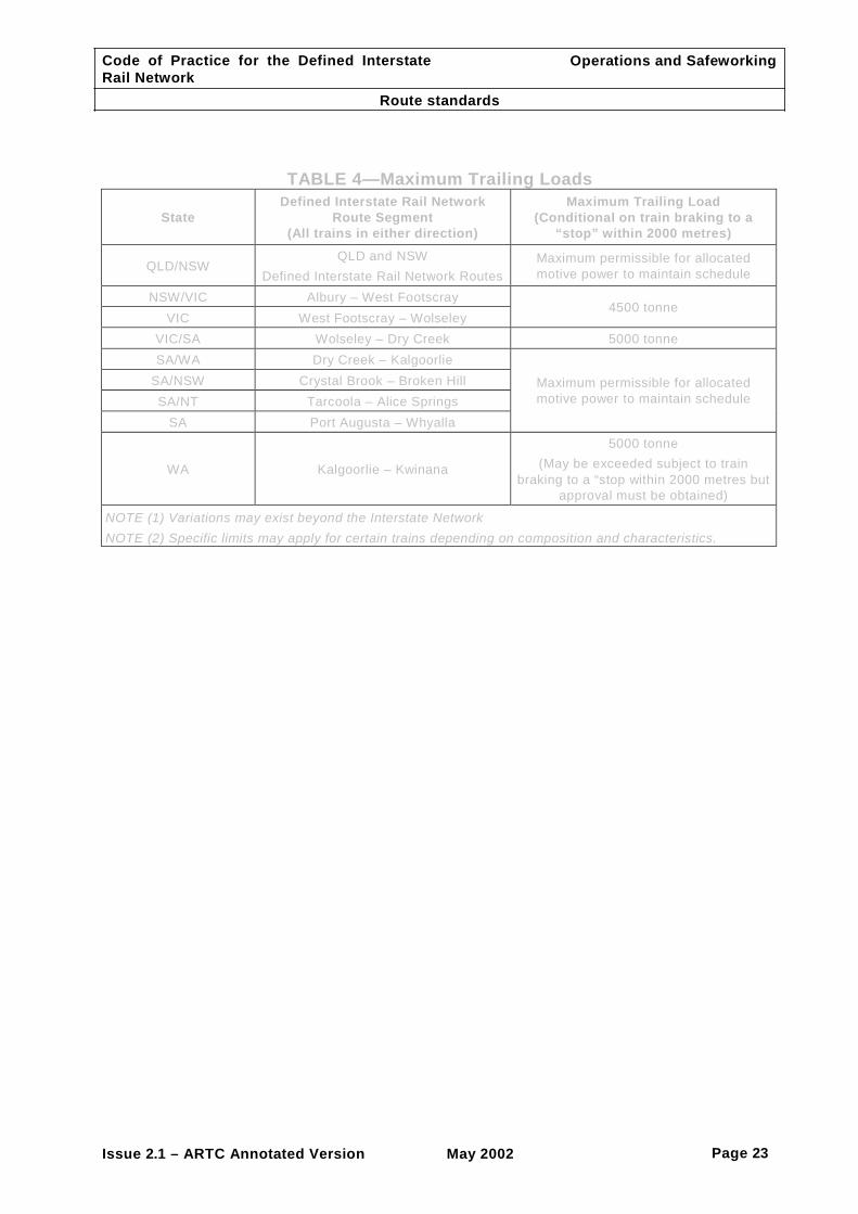
8.1 MAXIMUM TRAILING LOADS
Operators shall put into place systems to establish the trailing tonnage of each train before Defined Interstate Rail Network entry.
A guide to maximum trailing loads for each Defined Interstate Rail Network route segment is shown in TABLE 4.
NOTE: Specific limits may apply for certain trains depending on composition and characteristics.
8.2 STANDARD MARSHALLING REQUIREMENTS
Operators shall put into place systems to ensure compliance with the standard marshalling requirements, which include the following:
(a) Requirements of the Australian Code for the Transport of Dangerous Goods by Road and Rail; Sixth Edition.
(b) Requirements of Clause 15, Braking performance of trains.
(c) Limitations on trailing load imposed by draw gear classification.
(d) Vehicles with a gross mass on rail of less than 34 tonne should, wherever possible,
be marshalled towards the rear of freight trains.
(e) On the Adelaide-Melbourne-Sydney route, all vehicles with a gross mass on rail of 28 tonne or less shall be marshalled so that the trailing load on the foremost such vehicle is not more than 2600 tonne.
9 AXLE LOAD LIMITS
9.1 ROLLINGSTOCK AXLE LOAD LIMITS (EXCLUDING LOCOMOTIVES)
Operators shall put into place systems to ensure rollingstock axle load limits are not exceeded.
A guide to axle load limits (excluding locomotives) for each Defined Interstate Rail Network route is detailed in TABLE 5.
NOTE: Specific limits may apply for certain classes of rollingstock depending on individual characteristics.

Code of Practice for the Defined Interstate Rail Network
Route Standards
Operations and Safeworking
Issue 2.1 – ARTC Annotated Version May 2002 Page 7
9.2 LOCOMOTIVES AXLE LOAD LIMITS
Operators shall put into place systems to ensure locomotives do not exceed axle load limits.
Locomotive axle load limits are determined with the locomotive in full working order with full supplies of fuel, sand, coolant lubricants and safety equipment.
Locomotive axle load limits for the Defined Interstate Rail Network is 22 tonne. This limit may be exceeded where the network owner has granted local approval or approval at restricted speeds.
NOTE: Specific limits may apply for certain classes of locomotive depending on individual characteristics.
10 ROLLINGSTOCK
10.1 GENERAL REQUIREMENTS
Rollingstock requirements are detailed in the Code of Practice for the Defined Interstate Rail Network, Volume 5: Rollingstock. This Code incorporates engineering and operational standards and practices applicable to the design, construction and operation of the Railway Rollingstock for inter-system use.
10.2 ROLLINGSTOCK ALLOCATION (ROSTERING)
The operator shall put into place systems to undertake all requirements associated with the allocation and support of rollingstock to be used on the Defined Interstate Rail Network. This shall include the allocation of rollingstock that is:
(a) Certified for operation.
(b) Rated for the maximum axle load and track speed for the class or type of train it is to comprise.
(c) Fit for service in terms of its mechanical and electrical (if applicable) condition.
(d) Fit for purpose in terms of the task to be performed.
10.3 ROLLINGSTOCK OPERATIONAL LOADING LIMITS
The load for any item of rollingstock shall not exceed:
(a) The rated specified maximum load.
(b) The maximum axle load for the class of train (excluding locomotives).
10.4 SECURING OF LOADS AND ANCILLARY EQUIPMENT
The operator shall put into place systems to secure loads and ancillary equipment and ensure that the means used are fit for purpose.
The systems shall be designed so each train completes transit through the Defined Interstate Rail Network without impact upon the safe integrity of the train, other trains, track workers and their equipment, the infrastructure, public property, the general community or the environment.

Code of Practice for the Defined Interstate Rail Network
Route Standards
Operations and Safeworking
Issue 2.1 – ARTC Annotated Version May 2002 Page 8
11 LOCOMOTIVES
11.1 LOCOMOTIVE ALLOCATION (ROSTERING)
The operator shall provide the following:
(a) Systems which will allow all requirements associated with the allocation and support of locomotives to be undertaken. This shall include the allocation of locomotives that are—
(i) certified for operation;
(ii) rated for the track speed for the class or type of train to which it is allocated;
(iii) fit for service in terms of mechanical and electrical condition;
(iv) fit for purpose in terms of the task to be performed; and
(v) provisioned with sufficient supplies of fuel, sand, coolant lubricants as well as safety, safeworking and communications equipment.
(b) Advance advice to the network owner detailing planned locomotive movements.
(c) Timely advice of subsequent changes to locomotive allocation that may be required for operational reasons.
11.2 LOCOMOTIVE HAULING, AND HOLDING CAPABILITY
The allocation of locomotive power is at the discretion of the operator. This discretion is provided on the basis that the locomotives used shall have hauling capacity sufficient for maintaining section running times.
The operator shall put into place systems to ensure train crews are capable of handling their trains safely with the locomotives allocated over the various grades, conditions and operational requirements of the Defined Interstate Rail Network.
11.3 LOCOMOTIVE COMMUNICATIONS EQUIPMENT
REQUIREMENTS
The provision of locomotive based communication equipment required for the Defined Interstate Rail Network operations and safeworking shall be the responsibility of the operator.
The operator shall ensure that locomotive communications equipment is maintained and functional for the intended purpose.
11.4 MOBILE VOICE COMMUNICATIONS ARRANGEMENTS
Train Locomotives shall be fitted with voice communications equipment required for train driving and controlling on the Defined Interstate Rail Network. The requirements for voice communications equipment shall be as detailed in TABLE 6.
11.5 DATA COMMUNICATIONS ARRANGEMENTS
Train Locomotives shall be fitted with data communications equipment required for train driving and controlling on the Defined Interstate Rail Network. The requirements for data communications equipment shall be as detailed in TABLE 7.

Code of Practice for the Defined Interstate Rail Network
Route Standards
Operations and Safeworking
Issue 2.1 – ARTC Annotated Version May 2002 Page 9
12 EXAMINATION AND TESTING OF THE AUTOMATIC
TRAIN BRAKE ON LOCOMOTIVE HAULED TRAINS
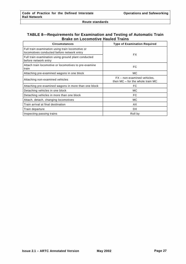
The operator shall put into place systems for the examination and testing of the automatic train brake on locomotive hauled trains.
The automatic train brake shall be examined and tested before a train departs from its origin, and whenever the brake pipe has in any way been affected by uncoupling locomotives or vehicles to, or detached from, a train.
The type of train examination and testing for various circumstances shall be conducted in accordance with the summary provided in TABLE 8.
13 BRAKE HOLDING TESTS FOR THE REARMOST VEHICLES (RETENTION TESTS)
The following apply:
(a) The operator shall put into place systems for conducting brake holding tests.
(b) The number of vehicles (or for articulated or permanently coupled vehicles the number of triple valve control units) required to conform to the requirements of this sub-section shall be:
(i) Three (3) for freight trains operated in New South Wales;
(ii) Two (2) for freight trains not entering New South Wales; and
(iii) One (1) for all passenger trains where a guard is provided or three (3) for passenger trains without guards.
(c) The vehicle operator shall ensure that air and hand brakes operate correctly.
(d) The air brakes on the vehicles shall remain effectively applied for a period of time, based on train length, considered sufficient for a member of the train (locomotive) crew to reach the vehicles and secure handbrakes in the event of a breakaway en route.
(e) This time shall be ten (10) minutes plus three (3) minutes for each 100 metres or part thereof of train length. For example, a train 1240 metres long will require a holding (retention) time of 13 x 3 + 10 = 49 minutes.
(f) If any of the required number of vehicles (as specified in Item (b) above) fail the above test (specified in Item (e) above), generally known as a holding or retention test, the faulty vehicle(s) shall be repaired or the train remarshalled to ensure compliance with the requirements of Items (c) and (d) above.
(g) Brake holding tests successfully completed will remain valid for departure within a period of 24 hours from completion of the test. After that period the vehicles shall be re-tested.
14 ROLL-BY INSPECTIONS
The operator shall put into place systems to carry out roll-by inspections during transit. The roll-by should be designed to provide visual inspection of a train to identify equipment, loading, security or other defects or failure while the train is moving. The following apply:
(a) Qualified workers shall carry out roll-by inspections whenever it is possible, safe and practicable to do so. During times of inclement weather, and/or in dark

Code of Practice for the Defined Interstate Rail Network
Route Standards
Operations and Safeworking
Issue 2.1 – ARTC Annotated Version May 2002 Page 10
locations, qualified workers are required to make a judgement about the appropriateness of these procedures to those circumstances.
(b) Where infrastructure and ground conditions allow a roll-by inspection to be done safely, during daylight hours, qualified workers should be on the ground, one each side of the train approximately 5 metres back from any passing train checking for any defects or problems.
(c) Where the qualified workers are train crews conducting crossings or passing during darkness, one crew member shall remain on the locomotive and utilise the head light to observe that side.
(d) Where the train crew consists of a driver only conducting crossing or passing, that driver shall remain on the locomotive to observe that side.
(e) In all cases, trains shall be observed to be complete by the end-of-train marker in position on the last wagon.
15 BRAKING PERFORMANCE OF TRAINS
15.1 STANDARD BRAKING PERFORMANCE (STOPPING DISTANCES)
Minimum operating requirements applicable to rollingstock of all types on any part of the Defined Interstate Rail Network can be found in Volume 5 - Rollingstock Code of Practice.
15.2 INOPERATIVE AIR BRAKES
In all cases, where it is necessary to isolate the air brakes on freight vehicles, the vehicle shall be green carded.
15.3 FREIGHT TRAINS
On freight trains, the maximum number of inoperative or isolated brakes permitted on a train shall be either of the following:
(a) One conventional two-bogie vehicle for every ten (10) vehicles in the train where the vehicle is isolated as a unit.
(b) One bogie for every ten (10) bogies in the train where individual bogies can be isolated or the isolation of triple valve control units affects more than two (2) bogies. This applies, only on the proviso that the total unbraked mass of the train shall not exceed 10% of the total train mass (excluding the mass of the hauling locomotives).
Item (a) above applies where the only vehicles isolated are conventional two-bogie vehicles. In all other cases, the requirements of Item (b) shall be followed.
For the purposes of this clause, a four-wheel (two-axle) vehicle shall be counted as one bogie, and locomotives under power shall not be counted as train vehicles.
15.4 PASSENGER TRAINS
On passenger trains, the number of vehicles permitted to run with the air brake inoperative or isolated shall be a maximum of:
(a) One (1) for every ten (10) vehicles (including the train locomotive when applicable); or
(b) One (1) bogie for every ten (10) bogies (including the train locomotive bogies when
applicable) where individual bogies can be isolated.

Code of Practice for the Defined Interstate Rail Network
Route Standards
Operations and Safeworking
Issue 2.1 – ARTC Annotated Version May 2002 Page 11
NOTE: Each locomotive is to be counted as one (1) vehicle or two (2) bogies for the purposes of this sub- section.
15.5 FOUR WHEELED OR BOGIE VEHICLES
The following apply:
(a) Any four-wheeled or bogie vehicles which have their brake control unit isolated shall not be marshalled adjacent to each other (ie. coupled together) on any freight train during departure or in transit.
(b) Where a group of one or more bogies have the brakes isolated or inoperative there shall be a group of at least the same number of bogies with operative brakes between the isolated bogies and the rear of the train, provided always that the requirements of Clause 12, Brake holding tests, have been met.
15.6 ARTICULATED OR PERMANENTLY COUPLED VEHICLES
Articulated or permanently coupled vehicles which are fitted with two (2) or more brake units may be coupled together on departure or in transit provided that there is no more than one brake unit isolated per vehicle and at least half the total number of bogies per vehicle have the air brake system fully functional.
15.7 VEHICLES WITH EXCESSIVE BRAKE TRAVEL
Vehicles with excessive brake travel or a defective slack adjuster and permitted to run with the air brakes operating shall, for the purposes of this sub-section, be considered as having the air brake inoperative or isolated.
15.8 GRADE CONTROL VALVES
The operator requirements are as follows:
(a) Grade control equipment provided on vehicles shall be tested and utilised when so instructed by the appropriate authority.
(b) Testing of the equipment is not normally required during train examination procedures of interstate trains before departure, except where specifically required for trains entering New South Wales.
(c) Trains entering New South Wales from South Australia shall have a minimum of 80% of tonnage fitted with grade control valves.
(d) Vehicles fitted with grade control valves shall be identified by a hollow circle on the
data panels.
(e) The exhaust rate with a grade control valve (for setting) (350 kPa to 70 kPa) shall be as shown below.
GRADE CONTROL VALVE EXHAUST RATES
Non-relayed systems
Relayed systems
EX— Nominally 15 seconds (15–20 seconds range)
EX— Nominally 15 seconds (15–20 seconds range)
IP— Nominally 50 seconds.
IP— Nominally 70 seconds
HP— Nominally 100 seconds
HP— Nominally 150 seconds
(f) The HP position shall retain 50 to 70 kPa brake cylinder pressure for a minimum period of five (5) minutes.

Code of Practice for the Defined Interstate Rail Network
Route Standards
Operations and Safeworking
Issue 2.1 – ARTC Annotated Version May 2002 Page 12
15.9 LOAD COMPENSATING EQUIPMENT
Vehicles fitted with load compensating brake equipment are identified by a hollow square on the data panels.
The change over load for manually operated equipment is normally indicated by a number within the square (or circle where grade control valves are fitted).
Operators shall put into place systems which will ensure that the following action is taken:
(a) The load compensating equipment is placed in the 'L' (Loaded) position when either—
(i) the payload (net load) in tonnes indicated by the vehicle way bill is greater than or equal to the number shown on the classification plate; or
(ii) if no number is shown, the payload is 20 tonnes or greater.
(b) At all other times the load compensating equipment is in the 'E' (Empty) position to avoid wheel damage from excessive braking.
15.10 BRAKE CYLINDER PISTON TRAVEL
Brake cylinder piston travel on vehicles shall be within the specified limits detailed in TABLE 9.
15.11 SLACK ADJUSTER AVAILABLE TRAVEL
The following apply:
(a) The minimum available slack adjuster travel, allowed before departure, is 50 mm.
(b) Where an air operated slack adjuster is defective and the brake piston travel is in excess of that given in TABLE 9, the air brake shall not be isolated, as the brake may still be capable of providing some retarding force. Any such vehicle shall be considered as an unbraked vehicle when determining brake percentage, and GREEN carded for attention.
(c) When a mechanical double acting (or in-line) slack adjuster is defective the air brake shall be isolated and the vehicle GREEN carded accordingly.
15.12 BRAKE BLOCK THICKNESS
The following apply:
(a) The measurement of brake block thickness is to be made on the outside (facing) surface at the thinnest end of the block in line with the toe (end) of the brake head.
(b) The permitted minimum brake block thickness at the commencement of a journey
on the Defined Interstate Rail Network which will enable a train to reach its destination without the need to renew brake blocks en-route, shall be as detailed in TABLE 10.
(c) The condemning thickness at any location for composition or cast iron brake blocks is 10 mm.
15.13 INOPERATIVE HANDBRAKES
Vehicles with inoperative handbrakes shall be clearly labelled with a NO HAND BRAKE card.
Code of Practice for the Defined Interstate Rail Network
Route Standards
Operations and Safeworking
Issue 2.1 – ARTC Annotated Version May 2002 Page 13
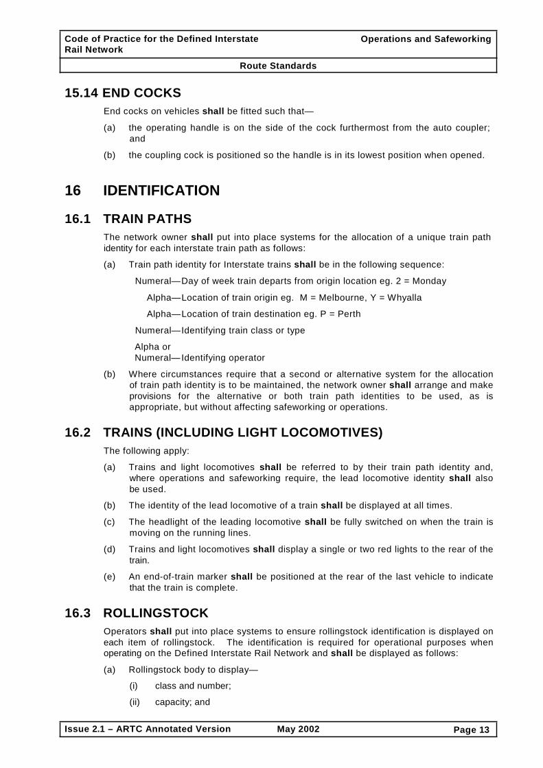
15.14 END COCKS
End cocks on vehicles shall be fitted such that—
(a) the operating handle is on the side of the cock furthermost from the auto coupler; and
(b) the coupling cock is positioned so the handle is in its lowest position when opened.
16 IDENTIFICATION
16.1 TRAIN PATHS
The network owner shall put into place systems for the allocation of a unique train path identity for each interstate train path as follows:
(a) Train path identity for Interstate trains shall be in the following sequence:
Numeral— Day of week train departs from origin location eg. 2 = Monday
Alpha— Location of train origin eg. M = Melbourne, Y = Whyalla
Alpha— Location of train destination eg. P = Perth
Numeral— Identifying train class or type
Alpha or Numeral— Identifying operator
(b) Where circumstances require that a second or alternative system for the allocation
of train path identity is to be maintained, the network owner shall arrange and make provisions for the alternative or both train path identities to be used, as is appropriate, but without affecting safeworking or operations.
16.2 TRAINS (INCLUDING LIGHT LOCOMOTIVES)
The following apply:
(a) Trains and light locomotives shall be referred to by their train path identity and, where operations and safeworking require, the lead locomotive identity shall also be used.
(b) The identity of the lead locomotive of a train shall be displayed at all times.
(c) The headlight of the leading locomotive shall be fully switched on when the train is moving on the running lines.
(d) Trains and light locomotives shall display a single or two red lights to the rear of the train.
(e) An end-of-train marker shall be positioned at the rear of the last vehicle to indicate that the train is complete.
16.3 ROLLINGSTOCK
Operators shall put into place systems to ensure rollingstock identification is displayed on each item of rollingstock. The identification is required for operational purposes when operating on the Defined Interstate Rail Network and shall be displayed as follows:
(a) Rollingstock body to display—
(i) class and number;
(ii) capacity; and

Code of Practice for the Defined Interstate Rail Network
Route Standards
Operations and Safeworking
Issue 2.1 – ARTC Annotated Version May 2002 Page 14
(iii) tare.
(b) Rollingstock bogies to display classification code and serial number.
NOTE: The following information may also be displayed on some bogies. • Date last overhauled • Date axle bearings last overhauled • Date axle bearings last greased • Type / model of side bearer fitted (where resilient constant side bearers are used)
16.4 TRACK VEHICLES AND MACHINES
The following apply:
(a) Track vehicles and machines shall be referred to by a unique identity displayed in the direction of movement when working as a train.
(b) When multiple track machines and vehicles are operating as a train, each track machine or vehicle shall display its unique identity.
(c) When track vehicles or machines work as a train, the network owner shall allocate a train identity number for the movement.
(d) When working as a train, track machines and vehicles shall display a white light to the front and a red light to the rear.
(e) All track vehicles and machines shall be fitted with electric tail lights and yellow rotating flashing lights which shall be operated when travelling on the track or when travelling or working within three metres from the nearest rail.
(f) Track vehicles and machines not fitted with lights shall only be used on track when accompanied by a vehicle or machine that is fitted with lights.
16.5 LOCATIONS
The following apply:
(a) Stations, terminals, yards, crossing loops and block locations shall be identified by their respective names.
(b) A track side location shall be identified by kilometre location expressed in kilometres and metres, and the name of the section in which it occurs.
(c) The name of the section shall consist of the two location names either side of the kilometre location.
16.6 LEVEL CROSSINGS
*** To Be Determined ***
17 TRAIN DOCUMENTATION
17.1 DOCUMENTATION REQUIREMENTS BEFORE NETWORK ENTRY
The following apply:
(a) The operator shall put into place systems to provide train control with a train manifest that accurately specifies the composition of the train and includes the following:

Code of Practice for the Defined Interstate Rail Network
Route Standards
Operations and Safeworking
Issue 2.1 – ARTC Annotated Version May 2002 Page 15
(i) the identity of each locomotive working or being hauled;
(ii) the name of each member of the train crew and of other persons travelling on the locomotive;
(iii) the total number of vehicles on the train;
(iv) the gross mass of the train in tonnes (including mass of locomotives working and hauled);
(v) the gross trailing mass of the train in tonnes (excluding mass of working locomotives);
(vi) the length of the train in metres;
(vii) vehicles with dangerous goods including the class of dangerous goods;
(viii) the identity and sequence of vehicles;
(ix) the gross mass of each vehicle;
(x) vehicles with out-of-gauge loading; and
(xi) the origin and destination of each vehicle.
(b) The operator shall provide the train manifest to the train control by:
(i) electronic data transfer, if available; or
(ii) photocopy, if convenient; or
(iii) otherwise, by facsimile.
17.2 ON TRAIN DOCUMENTATION
The operator shall put into place systems to ensure that the train crew operating the train has in their possession the following documentation:
(a) A brake test certificate declaring the following:
(i) correct braking function;
(ii) details of rollingstock with brakes cut out;
(iii) brake pipe leakage test results; and
(iv) the identity of rollingstock used in brake holding tests.
(b) A manifest specifying each item detailed in 16.1 (a).
(c) Dangerous goods documentation and applicable Emergency Procedure Guides (if dangerous goods are being transported).
(d) Applicable train notices and circulars.
(e) Applicable temporary speed restriction notices.
(f) Appropriate safeworking forms.
17.3 DOCUMENTATION REQUIREMENTS AFTER NETWORK ENTRY
The operator shall put into place systems to ensure:
(a) On-train documentation is amended to reflect changes to the train consist during its transit.
(b) Train control is advised of the changes.

Code of Practice for the Defined Interstate Rail Network
Route Standards
Operations and Safeworking
Issue 2.1 – ARTC Annotated Version May 2002 Page 16
17.4 NETWORK OWNER REQUESTED DOCUMENTATION
Upon request from the network owner the operator shall provide a copy of any of the documentation detailed in Clause 16.1(a).
17.5 DOCUMENTATION DISCREPANCIES AFFECTING
OPERATIONAL SAFETY
The following apply:
(a) Where the operator becomes aware of a documentation discrepancy the operator shall advise train control of the discrepancy.
(b) Where train control becomes aware of a documentation discrepancy train control
shall advise the operator of the discrepancy.
(c) Where the discrepancy impacts on the safe integrity of the train, train control shall arrange for the train to be stopped at the first available location where the train crew shall compare the on train documentation with the actual composition of the train.
(d) Details of any discrepancy found by the train crew shall be provided to train control and a brake test conducted, vehicles re-marshalled or detached as appropriate to rectify the discrepancy.
(e) Examples of documentation discrepancies that may affect safety are as follows:
(i) actual train length exceeds the documented train length;
(ii) actual wagon sequence varies from documented sequence;
(iii) actual wagons on the train vary from documented wagons on the train; and
(iv) actual mass or dimension exceeds documented mass or dimension.
(f) Once the discrepancy has been resolved and the safe integrity of the train assured, normal operations shall be resumed.
18 TIME
18.1 WATCHES AND CLOCKS
24-hour time shall be observed and used for the purpose of operations and safeworking.
18.2 TIME ZONES
The following apply:
(a) In each State and Territory, local time is observed with the following exceptions:
(i) at Broken Hill, eastbound arrivals and westbound departures shall observe central standard time;
(ii) at Cook, eastbound arrivals and westbound departures shall observe western standard time; and
(iii) at Alice Springs, arrivals and departures shall observe central standard time.
(b) Daylight saving time shall be observed on the dates promulgated.
Code of Practice for the Defined Interstate Rail Network
Route Standards
Operations and Safeworking
Issue 2.1 – ARTC Annotated Version May 2002 Page 17
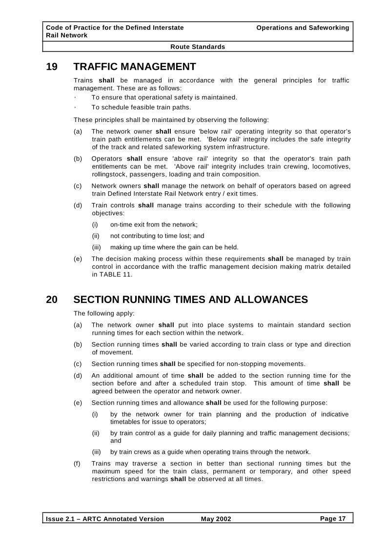
19 TRAFFIC MANAGEMENT
Trains shall be managed in accordance with the general principles for traffic management. These are as follows: • To ensure that operational safety is maintained. • To schedule feasible train paths.
These principles shall be maintained by observing the following:
(a) The network owner shall ensure 'below rail' operating integrity so that operator’s
train path entitlements can be met. 'Below rail' integrity includes the safe integrity of the track and related safeworking system infrastructure.
(b) Operators shall ensure 'above rail' integrity so that the operator's train path entitlements can be met. 'Above rail' integrity includes train crewing, locomotives, rollingstock, passengers, loading and train composition.
(c) Network owners shall manage the network on behalf of operators based on agreed train Defined Interstate Rail Network entry / exit times.
(d) Train controls shall manage trains according to their schedule with the following objectives:
(i) on-time exit from the network;
(ii) not contributing to time lost; and
(iii) making up time where the gain can be held.
(e) The decision making process within these requirements shall be managed by train control in accordance with the traffic management decision making matrix detailed in TABLE 11.
20 SECTION RUNNING TIMES AND ALLOWANCES
The following apply:
(a) The network owner shall put into place systems to maintain standard section running times for each section within the network.
(b) Section running times shall be varied according to train class or type and direction of movement.
(c) Section running times shall be specified for non-stopping movements.
(d) An additional amount of time shall be added to the section running time for the section before and after a scheduled train stop. This amount of time shall be agreed between the operator and network owner.
(e) Section running times and allowance shall be used for the following purpose:
(i) by the network owner for train planning and the production of indicative timetables for issue to operators;
(ii) by train control as a guide for daily planning and traffic management decisions; and
(iii) by train crews as a guide when operating trains through the network.
(f) Trains may traverse a section in better than sectional running times but the maximum speed for the train class, permanent or temporary, and other speed restrictions and warnings shall be observed at all times.

Issue 2.1 – ARTC Annotated Version May 2002 Page 18
Code of Practice for the Defined Interstate Rail Network
Route standards
Operations and Safeworking
TABLE 1—Infrastructure Arrangements Defined Interstate Rail Network
Major Route Segment [Electrified territory #]
Train Control Provider
and Location
Network Owner
Access Provider
Acacia Ridge – Roma Street # QR Mayne QR
QR Acacia Ridge – Fisherman Is.#
SRA
Broadmeadow Acacia Ridge – Greenbank Greenbank – Casino
RIC
RIC
Casino – Maitland Maitland – Broadmeadow Broadmeadow – Sydney # SRA
Sydney Sydney – Goulburn # Goulburn – Junee
SRA Junee Junee – Albury
Parkes – Cootamundra Broken Hill – Parkes
SRA Orange
Parkes – Orange East Fork Dubbo – Orange Orange East Fork – Spring Hill Spring Hill – Wallerawang Parkes – Merrygoen Merrygoen – Gulgong
SRA Broadmeadow
Gulgong – Muswellbrook Merrygoen – The Gap The Gap – Werris Creek Werris Creek – Antiene Antiene – Maitland Moss Vale – Dombarton
SRA Sydney
Dombarton – Scarborough Scarborough – Coal Cliff Coal Cliff – Sydney Albury – Wodonga
ARTC Adelaide
ARTC
ARTC
Wodonga – West Footscray West Footscray – Tottenham West Footscray – Spencer St flyover Dynon – Appleton Dock Tottenham – Newport Newport – Pyrenees Loop Pyrenees Loop – Wolseley Wolseley – Dry Creek Glanville – Pelican Point Dry Creek – Port Adelaide A Gillman Junction – Port Flat Dry Creek – Crystal Brook Crystal Brook – Broken Hill Crystal Brook – Coonamia Coonamia – Kalgoorlie Tarcoola – Alice Springs Port Augusta – Whyalla

Issue 2.1 – ARTC Annotated Version May 2002 Page 19
Code of Practice for the Defined Interstate Rail Network
Route standards
Operations and Safeworking
TABLE 1—Infrastructure Arrangements (continued) Defined Interstate Rail Network
Major Route Segment [Electrified territory #]
Train Control Provider
and Location
Network Owner
Access Provider
Kalgoorlie – West Merredin Westnet Merredin
Westnet
Westnet
West Merredin – Avon Westnet Northam Avon – Midland
Westnet Perth Midland – Forrestfield Midland – EP Terminal # Forrestfield – Kwinana Cockburn - Fremantle

Issue 2.1 – ARTC Annotated Version May 2002 Page 20
Code of Practice for the Defined Interstate Rail Network
Route standards
Operations and Safeworking
TABLE 2—Safeworking Systems
State Defined Interstate Rail Network Route Segment
Safeworking System
Approx. Route km
Number of Lines
QLD Acacia Ridge – Greenbank Signalled 17 Single QLD/NSW Greenbank – Casino Token 149 Single
NSW
Casino – Maitland
Signalled
641 Single
Maitland – Broadmeadow Double Broadmeadow – Hornsby 138 Double Hornsby – Epping 11 Double Epping – West Ryde 4 Four lines West Ryde – Rhodes 3 Double Rhodes – Concord West 2 Double Concord West – North Strathfield Jnc 2 Four lines North Strathfield Jnc – Flemington Jnc 3 Single Flemington Jnc – Chullora Junction 3 Double Junee - Ingleburn 440 Double Ingleburn – Glenfield Junction 4 Three lines Glenfield Jct – Sefton Pk Jcn via Villawood 21 Double Sefton Park Jcn – Chullora Junction 4 Double St Marys – Flemington Junction 31 Four lines Junee – Albury 160 Single Broken Hill – Bogan Gate Token
640 Single Bogan Gate – Parkes Communications Single Parkes – Cootamundra West Token Single Parkes – Orange East Fork
Communications 137 Single Dubbo – Orange 130 Single Orange East Fork – Spring Hill
Signalled
12 Double Spring Hill – Murrobo 21 Single Murrobo – Newbridge 14 Double Newbridge – Bathurst 33 Single Bathurst – Tarana 41 Double Tarana – Wallerawang 26 Single Wallerawang – Lithgow 14 Double Lithgow – St Marys 109 Double Moss Vale – Dombarton 52 Single Dombarton – Coniston 13 Double Coniston – Port Kembla 6 Double Coniston – Scarborough 22 Double Scarborough – Coal Cliff 3 Single Coal Cliff – Hurstville 44 Double Hurstville – Meeks Road Junction 8 Four lines Meeks Road Junction - Marrickville 2 Double Marrickville – Chullora Junction 10 Double Marrickville – Port Botany 10 Single
NSW/VIC Albury – Wodonga 6 Single
State
Emergency Diversionary Routes Safeworking
System Approx.
Route km Number of
Lines
NSW
Merrygoen – Gulgong
Token
67 Single Gulgong – Muswellbrook 172 Single Parkes – Merrygoen 247 Single Merrygoen – The Gap 183 Single The Gap – Werris Creek 7 Single Werris Creek – Antiene
Signalled 137 Single Antiene – Maitland 81 Double

Issue 2.1 – ARTC Annotated Version May 2002 Page 21
Code of Practice for the Defined Interstate Rail Network
Route standards
Operations and Safeworking
TABLE 2—Safeworking Systems (continued)
State Defined Interstate Rail Network Route Segment
Safeworking System Approx.
Route kms Number of
Lines
VIC
Wodonga – West Footscray
Signalled
301 Single West Footscray – South Dynon Junction 3 Double South Dynon Junction – North Dynon 2 Single South Dynon Junction – Spencer Street 3 Single South Dynon – Flinders Street 2 Double BG Flinders Street – Caulfield 11 4 lines BG Caulfield – Moorabbin 7 3 lines BG Moorabbin – Frankston 30 Double BG Appleton Dock Access Authority Working - - Frankston – Long Island Junction
Siding Conditions 19 Single BG Long Island Junction – Long Island 3 Single BG West Footscray – Tottenham Signalled 2 Single Tottenham – Newport Signalled 8 Single Newport – Pyrenees Loop Communications 251 Single
VIC/SA Pyrenees Loop – Dry Creek
Signalled
508 Single
SA
Dry Creek – Pt Adelaide 8 Single Glanville – Pelican Point 9 Single Birkenhead to Pelican Point Access Authority Working Single Gillman Junction – Port Flat
Signalled
3 Single Dry Creek – Crystal Brook 193 Single
SA/NSW Crystal Brook – Broken Hill 369 Single
SA Crystal Brook – Coonamia 22 Double Coonamia – Stirling North Communications 81 Single Stirling North – Spencer Jct Signalling 10 Single
SA/WA Spencer Jct – Kalgoorlie Communications 1907 Single SA Spencer Jct – Whyalla Communications 70 Single
SA/NT Tarcoola – Alice Springs Communications 814 Single
WA
Kalgoorlie – West Kalgoorlie
Signalled
5 Single West Kalgoorlie – Koolyanobbing 195 Single Koolyanobbing – Avon 340 Single Avon – Midland 101 Double Midland – Forrestfield 10 Double Midland – EP Terminal 14 Double Forrestfield – Cockburn
39 Double Cockburn – Kwinana Single Cockburn – Fremantle Communications 14 Single

Issue 2.1 – ARTC Annotated Version May 2002 Page 22
Code of Practice for the Defined Interstate Rail Network
Route standards
Operations and Safeworking
TABLE 3—Maximum Track Gradients (Ruling Grades)
Track Segment Ruling Grade
1 in
Track Segment Ruling Grade
1 in TBA
Issue 2.1 – ARTC Annotated Version May 2002 Page 23
Code of Practice for the Defined Interstate Rail Network
Route standards
Operations and Safeworking
TABLE 4—Maximum Trailing Loads
State Defined Interstate Rail Network
Route Segment (All trains in either direction)
Maximum Trailing Load (Conditional on train braking to a
“stop” within 2000 metres)
QLD/NSW QLD and NSW Defined Interstate Rail Network Routes
Maximum permissible for allocated motive power to maintain schedule
NSW/VIC Albury – West Footscray 4500 tonne
VIC West Footscray – Wolseley VIC/SA Wolseley – Dry Creek 5000 tonne SA/WA Dry Creek – Kalgoorlie
Maximum permissible for allocated motive power to maintain schedule
SA/NSW Crystal Brook – Broken Hill SA/NT Tarcoola – Alice Springs
SA Port Augusta – Whyalla
WA
Kalgoorlie – Kwinana 5000 tonne
(May be exceeded subject to train braking to a “stop within 2000 metres but
approval must be obtained) NOTE (1) Variations may exist beyond the Interstate Network NOTE (2) Specific limits may apply for certain trains depending on composition and characteristics.

Issue 2.1 – ARTC Annotated Version May 2002 Page 24
Code of Practice for the Defined Interstate Rail Network
Route standards
Operations and Safeworking
TABLE 5—A Guide to Rollingstock Axle Load Limits (excluding locomotives)
State
Defined Interstate Rail Network Route Segment
Rollingstock Axle Load Limit/Train Speed
(Maximum tonne / km/h)
QLD Acacia Ridge – Roma Street
19/115
21/100
23/80 Acacia Ridge – Fisherman Islands Acacia Ridge – Greenbank
NSW/QLD Greenbank – Sydney 25/80
NSW Sydney – Albury NSW/VIC Albury – Wodonga
21/100
21/100
21/80 VIC Wodonga - West Footscray
NSW
Broken Hill – Orange East Fork
19/115
21/100
23/80
Dubbo – Orange Orange East Fork – Wallerawang Merrygoen – Muswellbrook Parkes - Maitland Parkes – Cootamundra Moss Vale – Sydney
VIC West Footscray –Tottenham
19/115
21/110
23/80 Tottenham – Newport Newport – Wolseley
SA/WA Wolseley – Dry Creek – Kalgoorlie
19/115
21/110
23/80 SA/NSW Crystal Brook – Broken Hill SA/NT Tarcoola – Alice Springs
SA Port Augusta – Whyalla - -
WA
Kalgoorlie – Koolyanobbing
TBA
Koolyanobbing – Avon Avon – Midland Midland – EP Terminal Midland – Forrestfield Midland- Kwinana
NOTE: Specific limits may apply for certain classes of rollingstock depending on individual characteristic.

Issue 2.1 – ARTC Annotated Version May 2002 Page 25
Code of Practice for the Defined Interstate Rail Network
Route standards
Operations and Safeworking
TABLE 6—Locomotive Communications Requirements
State Defined Interstate Rail Network Route Segment
Voice Communications Equipment
QLD Acacia Ridge – Roma Street
UHF Radio & Hand Held Radio Acacia Ridge – Fisherman Is.
Acacia Ridge – Greenbank QLD/NSW Greenbank – Broadmeadow UHF/Satellite (RIC Country Net)
NSW
Broadmeadow – Sydney UHF Terrestrial Sydney – Albury
UHF/Satellite (RIC Country Net)
Broken Hill – Parkes Parkes – Cootamundra Parkes – Orange East Fork Dubbo – Orange Orange East Fork – Spring Hill Spring Hill – Murrobo Murrobo – Newbridge Newbridge – Bathurst Bathurst – Tarana Tarana – Wallerawang Merrygoen – Gulgong Gulgong – Muswellbrook Parkes – Merrygoen Merrygoen – The Gap The Gap – Werris Creek Werris Creek – Antiene Antiene – Maitland Moss Vale – Dombarton Dombarton – Scarborough UHF/Satellite (RIC Country Net)
UHF Terrestrial Scarborough – Coal Cliff Coal Cliff – Sydney
VHF Radio, Mobile Phone
VIC Albury – Wodonga Wodonga – West Footscray
VIC/SA West Footscray – Wolseley UHF Radio, Mobile Phone SA Wolseley - Dry Creek
UHF/VHF Radio, Mobile Phone SA/WA Dry Creek – Kalgoorlie
SA/NSW Crystal Brook – Broken Hill UHF Radio SA/NT Tarcoola – Alice Springs VHF Radio
SA Port Augusta – Whyalla VHF Radio, Mobile Sat
WA
Kalgoorlie – Avon UHF Radio, Mobile Phone where available Avon – Midland Trunk UHF Radio, Satellite phone Midland – Forrestfield Trunk UHF Radio Mobile Phone where available Midland – EP Terminal UHF Radio Mobile Phone where available Forrestfield – Kwinana Trunk UHF Radio Mobile Phone where available

Issue 2.1 – ARTC Annotated Version May 2002 Page 26
Code of Practice for the Defined Interstate Rail Network
Route standards
Operations and Safeworking
TABLE 7—Data Communications Arrangements Requirements
State Defined Interstate Rail Network Route Segment
Data Communications Equipment
VIC
Newport – Pyrenees Loop
Data Radio facility for Electronic Authority
Transmissions
Issue 2.1 – ARTC Annotated Version May 2002 Page 27
Code of Practice for the Defined Interstate Rail Network
Route standards
Operations and Safeworking
TABLE 8—Requirements for Examination and Testing of Automatic Train Brake on Locomotive Hauled Trains
Circumstances Type of Examination Required Full train examination using train locomotive or locomotives conducted before network entry
FX Full train examination using ground plant conducted before network entry Attach train locomotive or locomotives to pre-examine train
FC
Attaching pre-examined wagons in one block MC Attaching non-examined vehicles FX – non-examined vehicles,
then MC – for the whole train MC Attaching pre-examined wagons in more than one block FC Detaching vehicles in one block MC Detaching vehicles in more than one block FC Attach, detach, changing locomotives MC Train arrival at final destination AX Train departure DX Inspecting passing trains Roll by

Issue 2.1 – ARTC Annotated Version May 2002 Page 28
Code of Practice for the Defined Interstate Rail Network
Route standards
Operations and Safeworking
TABLE 9—Brake Cylinder Piston Travel Freight Vehicles Piston Travel
• Vehicles with unrelayed equipment and no slack adjuster 150-200 mm • Vehicles with unrelayed equipment and slack adjusters 150-200 mm • Vehicles fitted with relayed equipment 150-200 mm • Wabcopac or similar unitised brake equipment (according to manufacturers
instructions) 100-150 mm
Passenger Vehicles 25-125 mm Vehicles with bogie mounted brake cylinders • JSL (or similar) cylinders 60-65 mm • WF cylinders 75-100 mm
Vehicles with body mounted brake cylinders 125-175 mm

Issue 2.1 – ARTC Annotated Version May 2002 Page 29
Code of Practice for the Defined Interstate Rail Network
Route standards
Operations and Safeworking
TABLE 10—Minimum Brake Block Thickness Freight Trains (routes) Composition Cast Iron
Melbourne - Sydney or Sydney - Melbourne 15 mm 20 mm Sydney - Brisbane or Brisbane - Sydney 15 mm 20 mm Melbourne - Brisbane or Brisbane - Melbourne 15 mm 30 mm Adelaide/Pt Augusta - Perth or Perth - Adelaide/Pt Augusta 13 mm 15 mm Adelaide/Pt Augusta - Sydney 13 mm 20 mm Sydney – Adelaide/Pt Augusta 13 mm 15 mm Melbourne – Adelaide or Adelaide - Melbourne 13 mm 15 mm Adelaide - Brisbane or Brisbane - Adelaide 15 mm 20 mm
Passenger Train (routes) Composition Cast Iron Sydney - Perth or Perth - Sydney 15 mm 25 mm Sydney - Melbourne or Melbourne - Sydney 15 mm 15 mm Sydney - Brisbane or Brisbane - Sydney 13 mm 15 mm Adelaide - Perth or Perth - Adelaide 13 mm 15 mm Adelaide - Sydney 13 mm 20 mm Sydney - Adelaide 13 mm 15 mm Adelaide - Melbourne or Melbourne - Adelaide 13 mm 15 mm Adelaide - Pt Augusta - Alice Springs 13 mm 13 mm

Issue 2.1 – ARTC Annotated Version May 2002 Page 30
Code of Practice for the Defined Interstate Rail Network
Route standards
Operations and Safeworking
TABLE 11—Traffic Management Decision Making Matrix Train “A”—Current status
Train running “On Time”
Train running “Ahead “
Train running “Late”
Train “A”—Objective
OT Exit
OT Exit
1. Lose no more time
2. Make up time
3. Hold the gain
Tr
ain
“B”—
Cur
rent
sta
tus
Tr
ain
Run
ning
“O
n Ti
me”
Tr
ain
“B”—
Obj
ectiv
e O
T E
xit
Scheduled Cross
“A” or “B” Rule 2
B Rule 3
Tr
ain
runn
ing
“Ahe
ad “
O
T E
xit
A or B Rule 2
A or B Rule 2
B Rule 3
Tr
ain
runn
ing
“Lat
e”
1. L
ose
no m
ore
time
2. M
ake
up t
ime
3. H
old
the
gain
A Rule 1
A Rule 1
A or B Rule 4
Rule 1. Train “B” may be given priority on condition Train “A” will still meet OT objective. Rule 2. Both trains must meet their OT objective. Rule 3. Train “A” may be given priority on condition Train “B” will still meet OT objective. Rule 4. Give priority to the train where performance indicates it will lose least or no more time, and even
make up time and hold the gain. NOTES: The Traffic Management Decision Making Matrix is used as follows: [1] Train “A” and Train “B” are competing for priority in relation to traffic management decision by the train control, for
example Network entry, a cross or pass with another train in single line territory. [2] The controller compares the current “status” or performance of both trains in terms of running “On Time”, “Ahead”
or “Late”. [3] The decision is given to the train and Rule indicated at the point of intersection.