volume 37 number 1 january 2020
TRANSCRIPT

1
_________________________________________________________
VOLUME 37 NUMBER 1 January 2020 __________________________________________________________
The ATCO newsletter is the official publication of a group of amateur television operators known as
“AMATEUR TELEVISION IN CENTRAL OHIO Group Inc” published quarterly (January, April, July, and October)
Re-publication of ATCO newsletter material is encouraged as long as source credit is properly given.
Exception: “Reprinted by permission” material must have the original publisher’s permission.
_________________________________________________________ ATCO SPOTLIGHT TOPIC Thanks to Beasley, K6BJH (SK) for allowing us to share his cartoons.

2
____________________________________________________________ ACTIVITIES ... from my Workbench
Hey, I usually start out here talking about how bad the weather is…nope, not this time. I have
absolutely no room to complain. Moving on…
The repeater 439 interference is still there and I’ve had no word from the FCC about it. As you
probably remember, it’s a digital type of wide bandwidth RF signal present only at night
blocking the 439 MHz ATV repeater input. It now seems that the FCC doesn’t care as we’re
secondary users and it’s not blocking anyone else (to my knowledge). Reasoning it out, the FCC
office is in Chicago so it would take at least a team of two to travel here, stay overnight to check
it and go home the next day at a minimum. That’s stretching their resources so it’s my guess that they don’t really
care and if they wait long enough, it will go away on its own. I understand that reasoning based upon their strained
resources. Sooooooo…I’m thinking about taking matters in my own hands. I figure that if I find its exact location,
and list the exact coordinates, the FCC would be willing to issue an official memo to the interfering party to stop
transmitting. OK, that sounds good but how do I go about positively identifying the source given the fact that I’m
told I’m not allowed in the building where I suspect the interference is originating. Let me think about that one.
I’ve got it!!!! I’ll install a 439MHz TV transmitter at the repeater and connect it to our 439 receive antenna. I’ll
start transmitting at dusk and shut it off at dawn. The 439 input is useless to us the way it is so no harm to us but
I’m hoping it’ll cause interference to the one causing us interference. If I identify my ATV signal with my call
sign, I’m sure I’m legal. I’ll see if that works and let you know (if I’m not in jail).
The next hot topic is about the teleconference system we set up for the Tuesday night net on 147.48MHz. Instead
of streaming the video on BATC, we are now using a computer program called ZOOM, similar to Skype but
MUCH better and with almost no latency. The BATC system worked but the latency became intolerable starting
out as a few seconds but gradually increasing to minutes within about ½ hour. ZOOM is free to use and VERY
easy to install on the computer, I-pod or smartphone. It will handle up to 100 participants which is way more than
we need and it’s fully interactive so it is just like talking to a group in the same room. Now, it’s been said, “That’s
not HAM RADIO” (or ATV) which is correct. However, it’s a great introductory way of getting together and
discussing ATV. It only takes a computer which almost everyone has so prospective Hams can join in too.
Actually, we have had some non-Hams join us and say it’s nice to discuss the topic. They’ve been thinking about
joining and talking about potential receiver and transmitter choices!
Next, it’s about Jones Road linking to Dayton. Dave, AH2AR and I are
working on a DARA / ATCO link to connect us together. So far, we’ve
installed 1280 MHz loop yagi antennas pointing to both DARA and
ATCO. (That’s me pointing the DARA loop yagi toward them. The
ATCO loop antenna is above it.) We also have a 439 MHz rib cage slot
omni direction antenna that works well to receive both DARA and
ATCO as is. Dave has been using it with his “Gap-Filler repeater unit to
receive both DARA and ATCO. Then after about 2 weeks of perfect
operation, all of a sudden, the signals degraded. We think something
happened to the antenna, (I installed it over 15 years ago intended to be
used as a remote 439 ATV signal input). Since I’m not willing to climb
the tower to retrieve it in this weather (to the
50-foot level), activity is minimal till Spring
when my hands won’t stick to the tower
sections. More on that activity in the Spring.
That’s all for now. More later, Stay tuned!
...73 WA8RMC

3
____________________________________________________________
ATV NEWS FROM OTHER CLUBS 1 - I've heard about a small group of Amateur Radio TV operators in, Redding, California. The WR6TV
REDDING REPEATER AND ATV SOCIETY which operates on 3.4GHz output 500 mw. I'm going to find out
more about how they operate that simple but reliable setup, stay tuned.
2 - Tuesdays activity on the W6CX, Mt. Diablo ATV group is always interesting hearing more about systems
improvements both on the mountain top repeater site and back home with the ACAMPO 23cm transmitter updates
given by Bob, WB6ASU. Interest also on upgrading to DVB-S2 is one subject. W6ATN, lots of maintenance,
adjusts and upgrades being conducted by Mike, WA6SVT and the team. A DMR Talk-Group set up on 9410 for
those with DMR transceivers, can get you in as participant during the net ask your questions about current
activities with the group. No ATV equipment but want a taste of TV with the group, IP conference application,
"Whereby" can get you connected to ATN. Easy video meetings with no login or downloads. Video conferencing
with screen sharing, recording and much more.
3 - Wednesday nights with the W8BI Dayton, OH {ATN Affiliate] with David, AH2AR and Reuben, W8GUC
[Net-control] is a great network to visit. Great participation by the team. Technical show and tell by David are
always a pleasure to watch and learn. This past week more testing with the ATCO, WR8ATV group linking
project. You'll need to watch the DVR of the net to see and hear what I'm talking about.
4 - W2NYC, Ben [Net control] for K6BEN Silicon Valley ATV Group is a wonderful group leader for his team,
good participation by all, great signals on to the repeater, P5 video always.
5 - W0BTV- Boulder, CO - Jim Andrews, KH6HTV and Don, N0YE always present a great informative net. Jim
conducted a technical show-and-tell and I always learn so much from Jim. subject matter PA comparisons from
those Made in China compared to his products, Jim you win hi hi! And it’s always a pleasure to see and hear from
the members also. I always enjoy the travel videos from Jim, interesting indeed.
6 - No news or updates from Washington States, WW7ATS ATV Group in Seattle and the, W7AMQ ATV,
Portland, OR.
7 – SD | Oceanside DATV Group - Come January 2020 we will be taking both DATV repeaters out of service for
upgrades. Site One located in the City of San Diego [R1] and the Oceanside [R2] unit since they are twin systems.
The operating software to the matrix repeaters controllers will getting some major updates to help improve the auto
time slot linking processing, IP Ethernet port switching, Wifi/Bluetooth interface {remote maintenance related
application access} and more. The VR-Link DATV X-Band Repeater will cover our service area till the other units
are placed back in service since most of us live along the coast and can access the VR-Link unit. We are working
also on the Singapore DV transmitters adjusting for smaller bandwidth operation. The default lowest is set to 5
MHz the rest is just too wide for Amateur Radio TV. RF output adjustment via UART is no issue, a built in Class
A Liner PA is built in to the unit. We are trying to get this to where it is acceptable for bandwidth usage and
adjustment. Our goal DVB-T uses in 13cm and 23cm.
…Mario KD6ILO
News from San Diego I thought I'd share this with the group,
our RPA HL {Heavy Lift} Drone we call "SARDRONE". We did
a test flight early this morning near a experimental field near Chula
Vista, we did stay just below 350' since we were also testing new
motors for more lifting with an upgraded HD camera payload,
5.8Ghz FM transmitter package and smart phone as an airborne
hot spot and extra eyes using, Vsee, a video conferencing link.
…Mario KD6ILO

4
____________________________________________________________
HIDES BR-101E GAP-FILLER/REPEATER PRELIMINARY TESTING Preliminary testing of the BR-101EH used as a cross band demodulator/modulator link shows excellent potential
as one leg of a standalone cross band repeater. For the test, I provided a signal from a distant DVB-T transmitter
running on 428 MHz (Dayton W8BI DVB-T output) and prior to the test, set the parameters of the BR-101E for
the demodulator parameters of the incoming signal at 428 MHz with a 2 MHz bandwidth, QPSK constellation,
with 641/642 PID value (photo #1). I configured the modulator side of the BR-101E to transmit on 1280 MHz,
QPSK @ 2 MHz bandwidth, also set to the same PID values: 641/Video 642/Audio (photo #2).
The DVB-T RF output of the re-transmitted signal from the BR-101E is -18
dBm, and is adjustable with an internal attenuator/gain adjustment and the
system parameters are initially configured with a Windows PC. It’s
important to note that a personal
computer IS NOT required during
its operation. The unit has a
“DONGLE/SDR appearance” (see
photo) and a quick glance at the
HiDes advertisement would
wrongly infer that the dongle-
sized unit appears as if it would
require a computer for operation, (such as what is required for the HiDes
UT-100 transceiver dongle), but this is not the case. Consequently, being
standalone provides more reliable communication as computers in-the-loop
sometimes create problems during power failures or computer crashes and
are normally unusable at unattended sites.
The unit is powered by a 5 vdc USB cable. This same USB
cable that provides DC power is also used to initially
configure the system parameters with free software provided
by HiDes.
For the preliminary test, I used a MINI-CIRCUITS ZHL42W
amplifier as a means to increase the BR-101E’s transmitted
RF power up to approximately 1watt output (See photo) with
a resultant acceptable 30 dB shoulder. There are a number of
other amplifiers that can provide the necessary gain to bring
the BR-101E’s -18 dBm RF output up to a usable RF power
level, in order to drive an amplifier. We have yet to examine
whether filtering will be needed for out of band harmonics.
PHOTO #1: Straightforward
config. menu shows the GUI for
mod. / demod. Parameters.
PHOTO #2: GUI for PID
VALUE & Callsign Parameters
for modulation section
PHOTO #3: BR-101EH
transmitting with "Valid Green
LED" indicating demodulation in
progress. Directly plugged
into 5 VDC, with "gimmick"
antennas for 70cm and 23cm
antennas for testing in-shack.
PHOTO #4: Mini Circuits amplifier (driver) in line on the test bench with the BR-101EH Gap-filler/repeater.
(Note that the Bird 43 wattmeter is being used for relative RF output only... Wattmeter indicating ~ 1 watt)

5
When powered on, the BR-101E provides a continuous output with a blank raster (on 1280 MHz in this case) when
it is not receiving for about one minute after the received signal leaves the air, then the modulator ceases
transmission until another signal is received. It also has a CALLSIGN feature that can be set to any unique
callsign within its graphical user interface during initial configuration. The specified callsign/TS file transmission
functionality that allows for timed callsign display has not been explored yet, and more information about this
important function will be forthcoming. I was initially unable to understand how this function is properly
configured with the instructions provided. I will further explore this function.
When receiving a distant signal, it re-transmits whatever DVB-T signal it is receiving (with the configured
parameter values) and there is absolutely no degradation of the re-transmitted video as it uses a transport stream
internally between its demodulator and modulator so no video or audio data is lost. Although not clearly seen in
the photo, the two separate HDMI monitors show the HDMI signal on 439 MHz before entering the BR-101EH
and also the re-transmitted signal from the BR-101EH on 1280 Mhz. There is virtually no discernible difference in
video quality when compared side-by-side. Off angle viewing in the photo makes it appear there is a difference,
but there is none, honest!!
The Gap-filler output looked as good as the original signal being
transmitted, and for the preliminary test, the unit faithfully
retransmits the received video without loss of any resolution,
picture quality or detectable pixelating.
For cross-band repeater use it works superbly. I have as-of-yet to see whether it will work for in-band repeater use
because modulator/demodulator de-sensing will likely will be an issue, since there is no physical isolation between
modulator and demodulator and consequently likely won’t work for that purpose, but as I get further into this, I
will see whether this is feasible. Jeff at HiDes indicated that he did not believe the unit can be used as an in-band
repeater, but he stated that he is curious to hear what further testing may be unearthed.
Lastly, when it is demodulating a DVB-T signal, the PCB has a “green valid signal LED” that can be exploited to
switch a relay or provide other functions. The valid signal LED is used on other HiDes receivers for relay control
switching and there is no reason why this methodology can’t be employed with the BR-101E to support other
functions. The only limiter here is the surface mount LEDs are exceedingly small.
The unit gets very warm to the touch (but not hot) during extended operation and the heating could likely help to
bring it down to a lower operating temperature by fan cooling for repeater use. HOWEVER, note that when the
incoming received signal leaves the air, the unit stops transmitting in 60 seconds. When the signal comes back up,
the modulator once again becomes active/starts transmitting.
Pass-through latency is about 1 second, because there is no decoding and encoding occurring since a transport
stream is employed between its demodulator and modulator and is not going through a second encoding/decoding
step or analog to digital conversion. These and other functions need further checkout and I still have to figure out
how the callsign features work on this unit. It’s there, but the instructions are a little unclear (for me!) Hopefully,
Jim Andrews KH6HTV will be able to provide a further in-depth review of this unique "micro" Gap-filler/repeater
that literally can be lost inside your pocket.
…Dave AH2AR
PHOTO 5: HV122 1280 MHz receiver on the left side of
the bench is receiving the BR-101EH signal. The HV110
on the right is receiving the 439 MHz signal that is being
transmitted from the out-of-frame HV310. Comparison
of the re-transmitted signal on 1280 MHz is virtually
identical from the original DVB-T signal being received
on the right-hand-side HV110 receiver.

6
____________________________________________________________
ATCO FALL EVENT DETAILS I attended the ATCO Fall event on 27 October near Columbus. ATCO puts on an excellent twice-a-year get-
together. Ken W8RUT donated a number of door prizes and my ticket was the first to be drawn out of the barrel...
errr... hat and I walked away with a 440 MHz mobile radio... not ATV related but still a nice prize indeed! The
ATCO Newsletter took fourth place in the U.S. via an ARRL selection this year with good reason. Art always does
a terrific job in providing information of ATV interest to ATVers in the region. Maybe this note will show up in
next month's ATCO newsletter!
…AH2AR
ATCO members at the Westerville Fall event.
More door prizes than attendees... Good reason to
attend!
WB8CJW Dale programming four HV110s with a
channel list for repeater and simplex use

7
____________________________________________________________
OMNIVISION ANNOUNCES WORLD RECORD FOR SMALLEST IMAGE SENSOR by Bob Yirka, Tech Xplore
https://techxplore.com
Credit: OmniVision
OmniVision, a developer of advanced
digital imaging solutions, has
announced that it has won a place in
the Guinness Book of World Records
with the development of its OV6948
image sensor—it now holds the record
for the smallest image sensor in the
world. Along with the sensor, the
company also announced the
development of a camera module based
on the sensor called the
CameraCubeChip.
In its announcement on the company website, representatives of OmniVision suggest the main use for the new
sensor and camera module is for medical applications. They claim the camera module can be affixed to disposable
endoscopes to capture high-resolution images of very tiny parts of the body via blood vessels such as nerves, eye
parts, the heart, the spine, gynecological areas, inside joints and in parts of the urological system.
Reps for the company note that the U.S. Food and Drug Administration has recently pointed out that cross-
contamination issues related to the reuse of endoscopes requires prevention. The new camera, when used with new
disposable endoscopes, solves the problem by removing the need to reuse such devices.
Features of the new camera with the tiny sensor include a 120-degree field of vision along with a focus range of
three to 30 mm. The sensor has an image array that allows for 200 x 200 resolution and can process video at 30
fps. The camera also has an analog feature that transmits image data to a distance of four meters. The camera will
also be noticeably cooler than traditional probes, allowing for longer periods of use inside of patients—it consumes
just 25 mW of power.
The company also reports that the camera module has a wafer design and is just 0.65 mm x 0.65 mm square—and
it is just 1.158 mm thick, making it approximately the size of a grain of sand. OmniVision reps further note that its
small size allows its use in more than just endoscopes—it can also be used with guidewires and catheters. The
difference in size will no doubt be much appreciated by patients who have had to undergo uncomfortable and
sometimes painful invasive procedures with current technology. The company also hopes to expand the range of
potential users to include veterinarians, dental practitioners and those in industry.

8
____________________________________________________________
NATIONAL ATV NEWSLETTER????? Mario Badua KD6ILO proposes a National newsletter describing active projects in the USA. I respond by saying, OK, I take it that it is something you'd like to initiate, not something that currently exists. Right? It sounds like a new start to the now defunct ATVQ Magazine the editor wanted to re-start as an internet publication. Sounds great! Who will initiate that? Art.
Well Art, its' all of us in the U.S. that are active members of the Amateur Radio TV community. This is something
I want to share and start, maybe writing about what all of us are doing in the Amateur Radio image
communications sector, just knowing how well and what all of you are doing to bring together and improve our
participation, networks, sharing of technical improvements upgrades to our networks. I also try to find those ATV
stations {small clubs, societies etc.} that are in parts of the country that are hidden and bring them the information
that ATV has a very active network. Hope that answers part of your question? I found an ATV Society in Redding,
CA that I never heard of, WR6TV.
____________________________________________________________
3.4 AND 5GHz HAM BANDS MAY BE GOBBLED UP BY BROADBAND Attention Ham users of the 3.4 and possibly the 5GHz ham bands. We are likely to lose it! The broadband companies
need more bandwidth for their 5G operations and are willing to shell out money to get it. As a result the FCC is
asked to find space for them so they sharpened their pencils, found some infrequently used Ham Radio spectrum and
went to work. It’s my assumption that since the Hams put up less noise about it and are a weaker force, we’re a big
target. Below is summary of the rulemaking:
November 21, Shared Use in the 3.1-3.55 GHz Proposed Rulemaking - WT Docket No. 19-348
Background: The MOBILE NOW Act requires the Commission and the Department of Commerce to make
available new spectrum for mobile and fixed wireless broadband use, and further requires the Commission to work
with the National Telecommunications and Information Administration to evaluate whether commercial wireless
services and federal incumbents could share use of spectrum between 3.1 and 3.55 GHz. This Notice of Proposed
Rulemaking would propose to remove the existing non-federal allocations in the 3.3-3.55 GHz band as a step
towards potential future shared use between federal incumbents and commercial users. By taking the initial step
needed to clear the band of allocations for non-federal incumbents, the Commission furthers its continued efforts to
make more mid-band spectrum potentially available to support next generation wireless networks—consistent with
the mandate of the MOBILE NOW Act. What the NPRM Would Do: •Propose to clear the 3.3-3.55 GHz band of
existing non-federal users by removing the non-federal secondary radiolocation and amateur allocations in the 3.3-
3.55 GHz band;•Propose to relocate incumbent non-federal users out of the band;•Seek comment on relocation
options and transition mechanisms for incumbent non-federal users, either to the 3.1-3.3 GHz band or to other
frequencies; •Seek comment on how to ensure that non-federal secondary operations in the 3.1-3.3 GHz band will
continue to protect federal radar systems; and prepare the band for possible future shared use between commercial
wireless services and federal incumbents, potentially making as much as 250 megahertz of spectrum available for
flexible use, including 5G.
Of the frequencies between 3100 MHz and 3550 MHz, NTIA has identified the top 100 megahertz in the 3.45-3.55
GHz band as the most promising portion for sharing in the near term and is conducting a feasibility assessment in
collaboration with the Department of Defense and continues to study the feasibility of sharing in the entire 3.1-3.55
GHz band with existing and future federal users. Currently, the entire 3.1-3.55 GHz band is allocated for both
federal and non-federal radiolocation services, with non-federal users operating on a secondary basis to federal
radiolocation. It is my understanding that the proposal has been approved and awaiting a vote to put it into effect. We’ll see how it
turns out. Currently we have no operations in the 3.3 GHz band in the Columbus area.
…WA8RMC

9
____________________________________________________________
MORE INFO ABOUT THE 3.5GHz GHz BAND https://www.comsoc.org/publications/ctn/terahertz-communications-quest-spectrum
<https://www.comsoc.org/publications/ctn/terahertz-communications-quest-spectrum>
Terahertz Communications: The Quest for Spectrum
If there is a trend in wireless communications, it is the unrelenting increase in signal bandwidths. For decades,
bandwidths have increased within a restricted –and increasingly congested– frequency range in the microwave
realm, between 1 and 6 GHz, where radio propagation is favorable. Higher frequency bands were perceived as
inhospitable because of the harsh propagation conditions and the prohibitively expensive hardware. In recent years,
though, research has broken through the mmWave frontier, and early 5G deployments are underway with
components in the 30-GHz bands and above. Transmission ranges have become short enough to be compatible
with mmWave propagation, which in turn has revealed itself somewhat more benign than anticipated.
With higher frequencies gates open, perceptions have changed. Now it seems the sky is the limit, to the point
researchers are already looking into the sub-THz (100-300 GHz) and full THz realms, where many GHz of idle
bandwidth await.
… Jim A, KH6HTV
…and now ARRL responds,
ARRL to Oppose Proposal to Eliminate 3.3 - 3.5 GHz Amateur Allocation
At its December 12 open meeting, the FCC will consider adopting a Notice of
Proposed Rulemaking (NPRM) that proposes to remove the amateur radio 9-cm.
allocation at 3.3 - 3.5 GHz. ARRL plans to comment in opposition to the proposed action. According to an FCC
"Fact Sheet," the proceeding WT Docket 19-348, "Facilitating Shared Use in the 3.1 - 3.55 GHz Band," is a
follow-on from the MOBILE NOW Act, approved by the 115th Congress, which requires the FCC and the US
Department of Commerce to make available new spectrum for mobile and fixed wireless broadband use. It also
requires the FCC to work with the National Telecommunications and Information Administration (NTIA) to
evaluate whether commercial wireless services and federal incumbents could share spectrum between 3.1 and 3.55
GHz. NTIA manages spectrum allocated to federal government users.
"This Notice of Proposed Rulemaking would propose to remove the existing non-federal allocations in the 3.3 -
3.55 GHz band as a step towards potential future shared use between federal incumbents and commercial users,"
the FCC Fact Sheet explains. "By taking the initial step needed to clear the band of allocations for non-federal
incumbents, the Commission furthers its continued efforts to make more mid-band spectrum potentially available
to support next generation wireless networks."
The NPRM proposes to clear the 3.3 - 3.55 GHz band of existing non-federal users by removing non-federal
secondary radiolocation and amateur allocations [emphasis added] in the 3.3 - 3.55 GHz band and to relocate
incumbent non-federal users out of the band. The FCC would seek comment on relocation options and "transition
mechanisms" for incumbent non-federal users, either to the 3.1 - 3.3 GHz band or to other frequencies.
Regarding the Amateur and Amateur-Satellite Service allocations, the FCC NPRM asks whether existing amateur
spectrum in other bands might support operations currently conducted in the 3.3 - 3.5 GHz band. The 3.40 - 3.41
GHz segment is designated for amateur satellite communication. "We seek comment on the extent to which the
band is used for this purpose, whether existing satellites can operate on other amateur satellite bands, and on an
appropriate timeframe for terminating these operations in this band," the FCC NPRM says.
Also, at its December 12 meeting, the FCC will consider another NPRM in WT Docket 19-138 that would "take a
fresh and comprehensive look" at the rules for the 5.9 GHz band. The amateur radio 5cm allocation is 5650.0 -
5925.0 MHz, and the NPRM, if approved, would address the top 75 MHz of that amateur secondary band. ARRL
will also file comments opposing any changes affecting the 5-centimeter amateur allocation. Both draft FCC
proposals are subject to change prior to a vote at the December 12 FCC meeting.

10
____________________________________________________________
HOW DID WE BECOME KNOWN AS “HAMS” ? From the Assistant Section Manager John Perone, W8RXX
There are a few versions of the story how we became known as
“HAMS”. Here is one that perhaps makes sense. This comes
from the Florida Skip Magazine way back in 1959.
Have you ever wondered why radio amateurs are called
"HAMS?" Well, it goes like this: The word "HAM" as applied
to 1908 was the station call of the first amateur wireless
stations operated by some amateurs of the Harvard Radio Club.
They were ALBERT HYMAN, BOB ALMY and POOGIE
MURRAY.
At first, they called their station "HYMAN-ALMY-MURRAY". Tapping out such a long name in code soon
became tiresome and called for a revision. They changed it to "HY-AL-MU," using the first two letters of each of
their names. Early in 1901 some confusion resulted between signals from amateur wireless station "HYALMU"
and a Mexican ship named "HYALMO." They then decided to use only the first letter of each name, and the
station call became "HAM."
In the early pioneer days of unregulated radio amateur operators picked their own frequency and call-letters. Then,
as now, some amateurs had better signals than commercial stations. The resulting interference came to the
attention of congressional committees in Washington and Congress gave much time to proposed legislation
designed to critically limit amateur radio activity. In 1911 ALBERT HYMAN chose the controversial WIRELESS
REGULATION BILL as the topic for his Thesis at Harvard.
His instructor insisted that a copy be sent to Senator David I. Walsh, a member of one of the committees hearing
the bill. The Senator was so impressed with the thesis that he asked HYMAN to appear before the committee.
ALBERT HYMAN took the stand and described how the little station was built and almost cried when he told the
crowded committee room that if the bill went through that they would have to close down the station because they
could not afford the license fees and all the other requirements which the bill imposed on amateur stations.
Congressional debate began on the WIRELESS REGULATION BILL and little station "HAM" became the
symbol for all the little amateur stations in the country crying to be saved from the menace and greed of the big
commercial stations who didn't want them around. The BILL finally got to the floor of Congress and every speaker
talked about the "...poor little station HAM." That's how it all started. You will find the whole story in the
Congressional Record.
Nation-wide publicity associated station ""HAM" with amateur radio operators. From that day to this, and
probably until the end of time in radio an amateur is a "HAM."
…73, John W8RXX

11
____________________________________________________________
TEXAS DATV BALLOON LAUNCH The South Texas Balloon Launch Team - BLT launched the major flight of 2019 in late September with live DVB-
S2 video during the flight. The video signal chain was made up of Portsdown software running on a Raspberry Pi
3+ with a Pi Cam feeding a LimeSDR Mini driving a 1Watt linear amplifier at 1280 MHz. The transmit antenna
was a WA5VJB 'wheel' custom tuned to 1280 MHz and the receive antenna at the launch site was a yagi on an
auto-tracking AZ/EL system. A Minitiouner was used for the receiver. DVB-S2, QPSK, H264, SR1000 and 4:3
were chosen due to extensive but unscientific testing for signal lock and fast recovery when the signal was lost. P5
video was received and recorded with few drops from launch to the balloon burst altitude of over 115,000 feet and
a range of over 25 miles. A short You Tube video link: https://youtu.be/unVOdFurmcY
…Tom K5SAF
12
____________________________________________________________
SOLAR CYCLE 25 SUNSPOTS APPEAR December 30, 2019
New Solar Cycle 25 is on the way, but just when the transition from Solar Cycle 24 to Solar Cycle 25 will take
place is not entirely clear.
On December 24, two new sunspots - one in each hemisphere – emerged on the face of the Sun that exhibit the
reversed magnetic polarity marking them as belonging to Solar Cycle 25. According to Hale's Law, sunspot
polarities flip-flop from one solar cycle to the next, the National Center for Atmospheric Research explains.
"The Sun is currently in solar minimum - the nadir of the 11-year sunspot cycle," Tony Phillips said in his article,
"Reversed Polarity Sunspots Appear on the Sun" on the Spaceweather.com website. "It's a deep minimum,
century-class according to sunspot counts." The remarkable sunspot scarcity has prompted discussion of a possible
"extended minimum" akin to the Maunder Minimum in the 17th century, when no sunspots appeared for decades,
Phillips said. "Such an event could have implications for terrestrial climate." This article can be found online at,
https://spaceweatherarchive.com/2019/12/25/reversed-polarity-sunspots-appear-on-the-sun/
"Today's new-cycle sunspots (along with isolated new-cycle spots earlier this year) suggest that the solar cycle is,
in fact, unfolding normally," Phillips wrote, adding, a new Maunder Minimum does not appear to be in the offing.
Earlier this month, the NOAA/NASA-co-chaired international Solar Cycle Prediction Panel released its latest
forecast for Solar Cycle 25. The panel's consensus calls for a peak in July 2025 (+/- 8 months), with a smoothed
sunspot number of 115 and the solar minimum between Solar Cycles 24 and 25 occurring in April 2020 (+/- 6
months). If this solar minimum prediction is correct, it would make Solar Cycle 24 the seventh longest on record at
11.4 years.
The forecast can be found online at, https://www.swpc.noaa.gov/news/solar-cycle-25-forecast-update .
Climate scientist David Archibald speculates that the Solar Cycle 24/25 minimum could occur as late as March
2021, and that Solar Cycle 25 maximum might not happen until 2027.
"We are well into the Solar Cycle 24/25 minimum but [Cycle] 24 may not have ended yet," Archibald said in a
December 22 update on the "Watts Up With That?" website. "A solar cycle isn't over until the heliospheric current
sheet has flattened. And that could be as late as March 2021. Solar cycle amplitude does matter with respect to
climate and the amplitude of Solar Cycle 25, from projecting trends from the last three cycles, looks like being
about 80 in 2027."
The Solar Cycle Prediction Panel agreed that Solar Cycle 25 will be of average intensity and similar to Solar Cycle
24.
In an article posted on NOAA's Space Weather Prediction Center site, Scott McIntosh, the Director of the High
Altitude Observatory at National Center for Atmospheric Research (NCAR - https://ncar.ucar.edu/ ), stresses that
Solar Cycle 25 will happen, "but a sunspot cycle could be small."
Predictability comes with some physical understanding of the underlying process, McIntosh asserts. "The sunspot
cycle is erratic," he said in his presentation, "provocative of a chaotic turbulent solar interior where sunspot
progressions with time and latitude are the only tracers..."
...ARRL

13
____________________________________________________________
NEXT-GEN RADIO SYSTEM READY FOR SPACE STATION LAUNCH Amateur Radio on the International Space Station (ARISS) reports that its first Interoperable Radio System (IORS)
flight unit -- serial number 1001 -- has been delivered to NASA's Johnson Space Center for launch in early March.
The IORS represents the first major upgrade in ARISS equipment on the
International Space Station since Amateur Radio gained a permanent
presence onboard the ISS in 2000. In December, ARISS received approval
from NASA Safety to launch the IORS on SpaceX CRS-20 and stow the
radio system on the ISS for future installation.
"The IORS is a foundational element of the ARISS next-generation radio
system and is an incredible engineering achievement by the ARISS hardware
team," ARISS International President Frank Bauer, KA3HDO, said. "This
first element delivery will support easier radio mode transitions and enable
new, exciting capabilities for hams, students, and the general public."
The new system includes a higher-power radio, an enhanced voice repeater,
and updated digital packet radio (APRS) and slow-scan television (SSTV)
capabilities for both the US and Russian space station segments. The IORS consists of a custom-modified JVC
Kenwood TM-D710GA transceiver, an AMSAT-developed multi-voltage power supply, and interconnecting
cables.
The IORS set to launch in March will be installed in the ISS Columbus module; a second flight unit is expected to
be launched later this year for installation in the Russian Service module. The ARISS hardware team will assemble
four flight units -- and 10 IORS units in all -- to support onboard flight operations, training, operations planning,
and hardware testing.
"Future upgrades and enhancements to the next-generation system are in
various stages of design and development," Bauer said. "These include a
repaired Ham Video system -- currently planned for launch in mid-to-late
2020, L-band (uplink) repeater, ground command operations capability,
LimeSDR signal reception, a microwave 'Ham Communicator,' and Lunar
Gateway prototype experiment."
Bauer said a lot of "heavy lifting" remains to prepare the IORS for
operation on the space station. "ARISS has 92 engineering requirements
and our operations Phase III safety review to complete," he explained.
"The space agencies take a position of ‘trust, but verify'. Thus, these
engineering and safety 'verifications' all need to be closed out before the
IORS can be unstowed and turned on. This will be the ARISS hardware
team's focus over the next few months."
Bauer reminded that ARISS is almost entirely run by volunteers and
encouraged donations for next-generation hardware developments,
operations, education, and administrative functions.
ARISS International President
Frank Bauer, KA3HDO.

14
____________________________________________________________
EARLY DEVELOPMENT OF TELEVISION (From the Boulder ATV Newsletter) Roger Salaman, K0IHX
The invention of television evolved by the invention of
its components from the latter 1800’s to the FCC final
official standards for the industry in 1941. In 1926, Dr.
E. F. W. Alexanderson of General Electric Company of
Schenectady, New York experimented with revolving
mirrors to project a television image of motion pictures
on a screen. The next year, Dr. Alexanderson used a
scanning disc which revolved at 20 revolutions per
second. The first regularly scheduled television service
in the United States began on July 2, 1928, fifteen
months before television in the United Kingdom. The
Federal Radio Commission authorized C.F. Jenkins to
broadcast from experimental station W3XK in Wheaton
Maryland, a suburb of Washington, D.C. For at least the
first eighteen months, 48-line silhouette images from
motion picture film were broadcast, although beginning in the summer of 1929 he occasionally broadcast in
halftones. WRGB claims to be the world's oldest TV station, tracing its roots to an experimental station founded on
January 13, 1928, broadcasting from the General Electric factory in Schenectady, New York under the call letters
W2XB. It was popularly known as "WGY Television" after its sister radio station. Later in 1928, General Electric
started a second facility, this one in New York City, which had the call letters W2XBA, today known as WNBC.
The two stations were experimental in nature and had no regular programming because receivers were operated by
engineers within the company. The image of a Felix the Cat doll rotating on a turntable was broadcast for 2 hours
every day for several years as the new technology was being tested by the engineers.
The FCC adopted NTSC television engineering standards on May 2, 1941, calling for 525 lines of vertical
resolution, 30 frames per second with interlaced scanning, 60 fields per second, and sound carried by FM. Sets
sold since 1939 that were built for slightly lower resolution could still be adjusted to receive the new standard. The
FCC saw television ready for commercial licensing and the first such licenses were issued to NBCTV and CBS-
owned stations in New York on July 1, 1941followed by Philco's station WPTZ in Philadelphia.
The effect of World War II in 1942 significantly affected the progression of television with induction into military
service and the need for greater production war equipment. About 7,000 - 8,000 television sets were made in the
U.S. before the War Production Board halted manufacture in April 1942, production resuming in August 1945.
Television usage in the western world skyrocketed after WWII with the lifting of the manufacturing freeze, war-
related technological advances, the decrease in television prices caused by mass production, increased leisure time,
and additional disposable income. While only 0.5% of U.S. households had a television in 1946, 55.7% had one in
1954, and 90% by 1962.
After the U.S. entry into World War II, the FCC reduced the required minimum air time for commercial television
stations from 15 hours per week to 4 hours. Most TV stations suspended broadcasting; of the ten original television
stations only six continued through the war. On the few that remained, programs included entertainment such as
boxing and plays, events at Madison Square Garden, and illustrated war news as well as training for air raid
wardens and first aid providers. In 1942, there were 5,000 sets in operation, but production of new TVs, radios, and
other broadcasting equipment for civilian purposes was suspended from April 1942 to August 1945.
Following the rapid rise of interest in television after the war, the FCC was flooded with applications for television
station licenses. With more applications than available television channels, the FCC ordered a freeze on processing
station applications in 1948 that remained in effect until April 14, 1952.
15
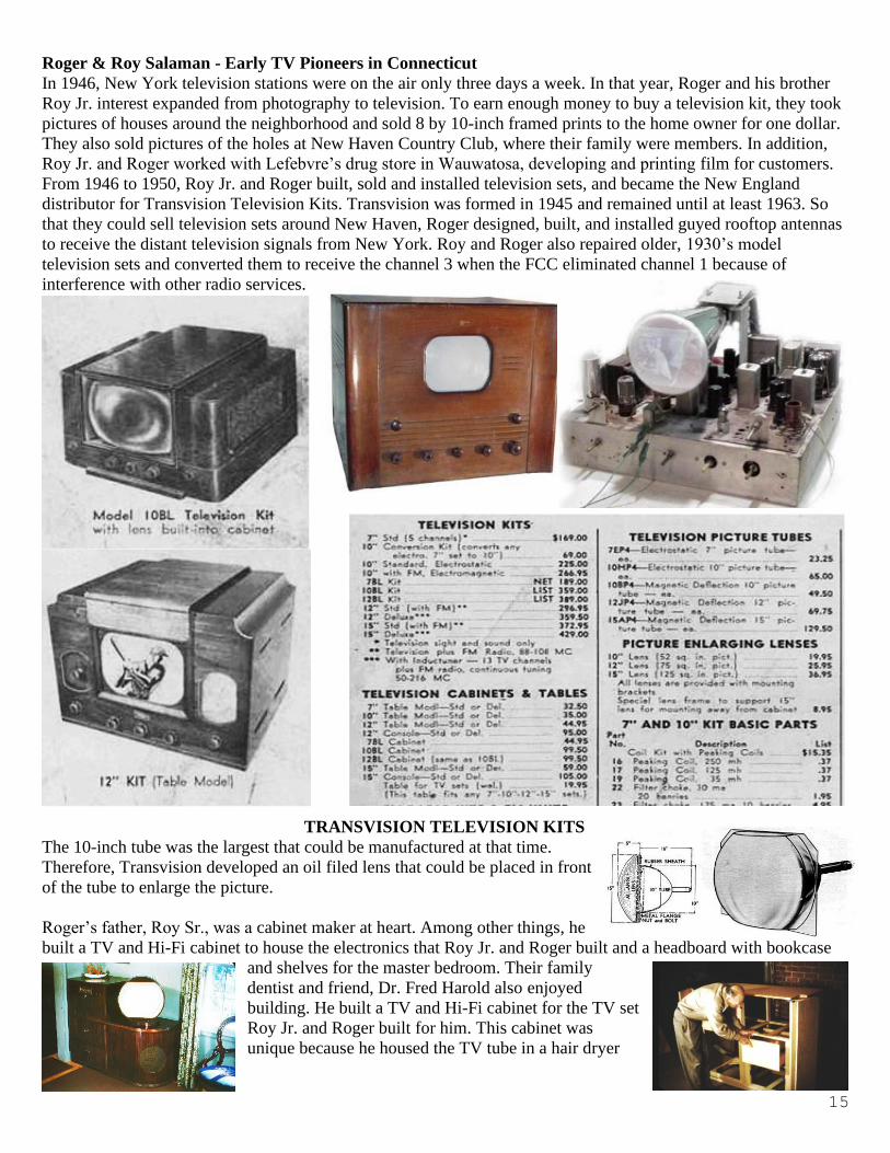
Roger & Roy Salaman - Early TV Pioneers in Connecticut
In 1946, New York television stations were on the air only three days a week. In that year, Roger and his brother
Roy Jr. interest expanded from photography to television. To earn enough money to buy a television kit, they took
pictures of houses around the neighborhood and sold 8 by 10-inch framed prints to the home owner for one dollar.
They also sold pictures of the holes at New Haven Country Club, where their family were members. In addition,
Roy Jr. and Roger worked with Lefebvre’s drug store in Wauwatosa, developing and printing film for customers.
From 1946 to 1950, Roy Jr. and Roger built, sold and installed television sets, and became the New England
distributor for Transvision Television Kits. Transvision was formed in 1945 and remained until at least 1963. So
that they could sell television sets around New Haven, Roger designed, built, and installed guyed rooftop antennas
to receive the distant television signals from New York. Roy and Roger also repaired older, 1930’s model
television sets and converted them to receive the channel 3 when the FCC eliminated channel 1 because of
interference with other radio services.
TRANSVISION TELEVISION KITS
The 10-inch tube was the largest that could be manufactured at that time.
Therefore, Transvision developed an oil filed lens that could be placed in front
of the tube to enlarge the picture.
Roger’s father, Roy Sr., was a cabinet maker at heart. Among other things, he
built a TV and Hi-Fi cabinet to house the electronics that Roy Jr. and Roger built and a headboard with bookcase
and shelves for the master bedroom. Their family
dentist and friend, Dr. Fred Harold also enjoyed
building. He built a TV and Hi-Fi cabinet for the TV set
Roy Jr. and Roger built for him. This cabinet was
unique because he housed the TV tube in a hair dryer

16
so that it could be turned in any direction. Dr. Harold was President of the American Dental Association.
By 1947 when there were 40 million radios in the U.S., there were about 44,000 television sets (with probably
30,000 in the New York area). Regular networked TV broadcasts began on NBC on a three-station network linking
New York with the Capital District and Philadelphia in 1944; on the DuMont TV Network in 1946, and on CBS
and ABS in 1948. Roger’s mother, Bernie, wrote to the New Haven Register, asking them to publish the television
schedule, and they responded that there was not enough demand for television. On June 25, 1948, our parents
invited a full living room of friends over to watch the Joe Louis, Jersey Joe Walcott boxing match on two 10 inch
black and white television sets that Roy Jr. and Roger built.
Roy Jr. and Roger Worked for New Haven Connecticut WNHC-TV
The New Haven Connecticut TV Station WNHC-TV went on
the air June 15, 1948 as channel 6, 6
days after WBZ-TV in Boston, thus just
missing being the first operational
television station in New England.
WNHC was the first TV service for
Hartford, Springfield, the Hamptons and
Eastern Long Island. In 1946, Roger had built multiple
element antennas and mounted them on home roofs so long-
distance reception of television signals from New York city
was possible. WNHC-TV moved to Channel 8 on January 1,
1954. The call letters then became WTNH in 1971. WNHC, with transmitter located on Gaylord Mountain, 8 miles
from New Haven, was the first station to bring network TV to Connecticut. WNHC was the first DuMont affiliate.
In the 1946, DuMont began operation as America's fourth television network, with headquarters and television
station, WABD in New York City. Hindered by a lack of primary stations and a small budget and by being forced
to utilize UHF affiliates in an era when UHF was not competitive, DuMont never achieved the success of the other
networks, and folded its television network in 1956.
On its first day of operation, June 15, 1948, WNHC and ran shows like Bishop Fulton Sheen's Life is Worth
Living. The 1948 Democratic and Republican national conventions, at which Harry Truman and Thomas Dewey
were nominated respectfully, were also broadcast live. At this early stage of television, newscaster, Ben Grawer,
provided a real-time view of the transmitter and antenna on the Empire State Building. Television was very
informal, and the newscasters did not wear coats.
In 1948, Roger and his brother, Roy Jr. visited the WNHC-TV transmitter after reading in the New Haven Register
about the Elm City Broadcasting Company building of the television station for New Haven. Roy and Roger talked
to the chief engineer, Mr. deLaurentis, who said Roy, who was 18 years old, could work as a TV cameraman in the
studio, and Roger, who was 16 years old, and a Freshman at New Haven High School, was given the job to run the
relay station on Oxford Hill, Connecticut. Since Roger didn’t have a First-Class Radio Telephone License, Mr.
deLaurentis said he should obtain a Third-Class Radio Telephone License and tell anyone that he was supervised
by a First- Class Licensee, Mr. deLorentis.
Roger Operated the Television Relay Station. At the relay station, besides switching to the correct network signal
on the hour or half-hour, Roger needed to maintain a quality signal for transmission to the TV transmitter on
Gaylord Mountain. For pickup of the off-the-air signals, Roger had to switch the television signal to the correct
channel and tune the RF section of the receiver for the best quality signal according the video signal on an
oscilloscope. Therefore, during the 30 second station break, he fine-tuned the RF signal for best quality, and
adjusted the synchronization signal to meet the FCC standard. More times than not, he finished making these
adjustments while WNHC-TV was on the air carrying the appropriate television signal for public viewing.

17
The Oxford Hill Relay station was halfway between New York, where the programs originated, and the WNHC-
TV transmitter in New Haven, Connecticut. The relay station had a Microwave transmitter at the bottom of a
wooden pole, with a parabola pointed straight up to a reflector which allowed the microwave signal to be beamed
to the microwave parabola receiving antenna on a tower at the Gaylord Mountain transmitter station.
The New York signals from WABD, CBS, and NBC were received on a yagi antenna mounted at the top of the
wooden pole. Later Roger built and installed a sloping-V antenna to improve the TV reception. The signal was fed
inside the relay station to a fixed frequency crystal receiver tuned to receive the WABD signal on Channel 5. The
signal from the antenna was also fed to an RCA 630 television set to receive the signals from CBS and NBC on
Channels 2 and 4.
Roger’s job was to assure the relay station operated correctly to receive the WABD, WCBS and WNBC signals,
convert the correct signal, according to the schedule of which station was to be carried by WNHC-TV at that
particular time, to microwave, and beam it to the WNHC-TV transmitter on Gaylord Mountain. The WNHC-TV
transmitter personnel and Roger established communications by normal telephone calls. There were other
externalities associated with this job. Hurricanes Edna, Carol and Hazel pounded New England in the 1950’s and
knocked the relay station as well as the New Haven television station WNHC-TV off the air. To get the Oxford
Hill relay station on the air as soon as possible, Roger drove around debris-littered roads and activated an
emergency power generator at the relay station. Roger put the relay station on the air providing the New Haven
area with information concerning the hurricane.
Besides its early affiliation with WABD,
WNHC-TV was also affiliated with NBC in
1949, CBS by 1949 and ABC by 1950. Because
of the concurrent affiliations, WNHC was able
to cherry pick the best TV programs and present
them to Connecticut viewers. Roger selected the
appropriate program when operating the
WNHC-TV, New-York to New Haven
television relay station in Oxford Connecticut,
halfway between New York and New Haven.
WNHC-TV moved to Channel 8 on January 1, 1954. The call letters became WTNH in 1971.
REFERENCES:
1. History of Television: https://en.wikipedia.org/wiki/History_of_television
2 Transvision Television Kits: http://www.earlytelevision.org/transvision.html
3. "Early Involvement with Television", Roger Salaman, K0IHX, ATVQ, Winter, 2015, pp. 24-25
Roger, K0IHX, and Naomi, KD0PDZ have been active in Boulder ATV
since 2008. Roger has an interesting background. During the 1950s & 60s
he did fundamental ionospheric radio research at NBS' Central Radio
Propgation Lab here in Boulder. In the 70s & 80s he worked in the White
House Office of Telecommunications Policy. For more about Roger &
Naomi, see the Sept. 2018, issue #3, ATV newsletter, pp. 3-4.
“Off the air” photo taken via the Boulder TV repeater.
…Article courtesy of Jim Andrews, KH6HTV in Boulder, Colorado.

18
___________________________________________________________ LOCAL HAMFEST SCHEDULE This section is reserved for upcoming Hamfests. They are limited to Ohio and vicinity easily accessible in one day.
Anyone aware of an event incorrectly or not listed here; notify me so it can be corrected. This list will be amended, as
further information becomes available. To see additional details for each Hamfest, Control Click on the blue title and
the magic of the Internet will give you the details complete with a map! To search the ARRL Hamfest database for
more details, CTL click ARRLWeb: Hamfest and Convention Calendar …WA8RMC.
01/19/2020 | Sunday Creek Hamfest Location: Nelsonville, OH
Type: ARRL Hamfest
Sponsor: Sunday Creek Amateur Radio Federation
Location: Strasburg, OH
01/26/2020 | Tusco Hamfest Type: ARRL Hamfest
Sponsor: Tusco Amateur Radio Club
Website: http://www.tuscoarc.org
02/16/2020 | Mansfield Hamfest Location: Mansfield, Ohio
Type: ARRL Convention
Sponsor: InterCity Amateur Radio Club
Website: http://www.iarc.club
03/14/2020 | Toledo Hamfest Location: Perrysburg, OH
Type: ARRL Convention
Sponsor: Toledo Mobile Radio Association
Website: http://www.tmrahamradio.org
03/21/2020 | Mid-Ohio Valley Hamfest Location: Gallipolis, OH
Type: ARRL Hamfest
Sponsor: Mid-Ohio Valley Amateur Radio Club, Inc.
Website: http://sites.google.com/site/midohiovalleyarc/
04/11/2020 | Cuyahoga Falls Hamfest Location: Cuyahoga Falls, OH
Type: ARRL Hamfest
Sponsor: Cuyahoga Falls Amateur Radio Club, Inc.
Website: http://www.cfarc.org/hamfest.php
04/26/2020 | Athens Hamfest Location: Athens, OH
Type: ARRL Hamfest
Sponsor: Athens County Amateur Radio Association
Website: http://www.ac-ara.org/
06/06/2020 | FCARC Summer
Hamfest Location: Wauseon, OH
Type: ARRL Hamfest
Sponsor: Fulton County Amateur Radio Club
Website: http://k8bxq.org/hamfest
07/19/2020 | Van Wert Hamfest Location: Van Wert, OH
Type: ARRL Hamfest
Sponsor: Van wert Amateur Radio Club
Website: http://w8fy.org
08/01/2020 | 2020 Columbus, Oh
Hamfest Location: Grove City, OH
Type: ARRL Hamfest
Sponsor: Voice of Aladdin/ Audio Unit of
Aladdin Shrine
Website: http://columbushamfest.com
12/07/2019 | Fulton County ARC
Winterfest Location: Delta, OH
Type: ARRL Hamfest
Sponsor: Fulton County Amateur Radio Club
Website: http://k8bxq.org/hamfest

19
____________________________________________________________ TUESDAY NITE NET ON 147.48 MHz SIMPLEX Every Tuesday night @ 9:00PM WA8RMC hosts a net for the purpose of ATV topic discussion. There is no need to
belong to the club to participate, only a genuine interest in ATV. All are invited. For those who check in, the general
rules are as follows: Out-of-town and video check-ins have priority. A list of available check-ins is taken first then a
roundtable discussion is hosted by WA8RMC. After all participants have been heard, WA8RMC will give status and
news if any followed by late check-in requests or comments. We usually chat for about ½ hour so please join us
locally or via internet at https://batc.org.uk/live/wr8atv/. Click on WR8ATV.
_____________________________________________________________ ATCO TREASURER'S REPORT - de N8NT OPENING BALANCE (10/20/19) .............................………………………...….$ 3521.70
Receipts (dues)….........................…....................................……………….……...$ 170.00
Cash Donation……… ………………………………………………………….$ 250.00
Fall Event food……………………………………………………………………$ (156.73)
PayPal fees…………………………………………………………….……….…. $ ( 5.31)
CLOSING BALANCE (01/20/20) ………….…………….…………….……...$ 3779.66

20
_____________________________________________________________ ATCO REPEATER TECHNICAL DATA SUMMARY Location: Downtown Columbus, Ohio
Coordinates: 82 degrees 59 minutes 58 seconds (longitude) 39 degrees 57 minutes 47 seconds (latitude)
Elevation: 630 feet above the average street level of 760 feet (1390 feet above sea level)
TV Transmitters: 423.00 MHz DVB-T, 10 W contin, FEC=7/8, Guard=1/32, Const=QPSK, FFT=2K, BW=2MHz, PMT=4095, PCR=256, Video=256, audio=257
427.25 MHz Analog VSB AM, 50 watts average 100 watts sync tip (cable channel 58)
1258 MHz 40 watts FM analog
1268 MHz DVB-S QPSK 20W continuous. SR=3.125MS, FEC=3/4, PMT=32, Video=162, Teletext=304, PCR=133, Audio=88, Service =5004)
Channel 1 is fed from all receivers. Channel 2 is fed direct from 439.25 analog receiver only.
2397 MHz Mesh Net transceiver 600mw output (channel 1 minus 2). ID is WR8ATV-2
10.350 GHz: 1 watt continuous analog FM
Link transmitter: 446.350 MHz: 5 watts NBFM 5 kHz audio. This input is a secondary input and used for control signals.
Identification: 423, 427, 1258, 1268 MHz, 10.350 GHz transmitters video ID every 10 min. with active video and information bulletin board every 30 minutes.
423 MHz digital, 1268 MHz digital & 10.350 GHz analog - Continuous transmission of ATCO & WR8ATV with no input signal present.
Transmit antennas: 423.00 MHz - 8 element Lindsay horizontally polarized 5 dBd gain “omni”
427.25 MHz - Dual slot horizontally polarized 7 dBd gain “omni” major lobe east/west, 5dBd gain north/south
1258 MHz - Diamond vertically polarized 12 dBd gain omni
1268 MHz - Diamond vertically polarized 12 dBd gain omni
2397 MHz - Ubiquiti dual polarity omni 13dBi gain slot for channel 1 minus 2 MESH Rx/Tx operation
2397 MHz - Comet Model GP24 vertically polarized 12 dBd gain omni (Used for experimental Mesh operation)
10.350 GHz - Commercial 40 slot waveguide horizontally polarized 16 dBd gain omni
Receivers: 147.480 MHz - F1 audio input with touch tone control. (Input here = output on 446.350)
439.000 MHz - DVB-T QPSK, 2MHz BW. Receiver will auto configure for FEC’s. (Input here = output on all TV transmitters)
439.250 MHz - A5 NTSC video with FM subcarrier audio, lower sideband. (Input here = output on all TV transmitters & also direct to
1268 MHz DVB-S output channel 2.)
449.975 MHz - F1 audio input aux touch tone control. 131.8 Hz PL tone. (Input here = output on 446.350).
1288.00 MHz - F5 video analog NTSC. (Input here = output on all TV transmitters)
1288.00 MHz - DVB-S QPSK SR=4.167MS, fec=7/8. PIDs: PMT=133, PCR=33, Video=33, Audio=49 (Input here=output on all Transmitters)
2398.00 MHz - F5 video analog NTSC. (Input here = output on all TV transmitters) (inactive at this time because of MESH on 2397)
10.450 GHz - F5 video analog NTSC. (Input here = output on all TV transmitters)
Receive antennas: 147.480 MHz - Vert. polar. Diamond 6dBd dual band (Shared with 446.350 MHz link output transmitter)
438.00/439.250 MHz - Horizontally polarized dual slot 7 dBd gain major lobe west (Shared with 438 & 439 receivers)
1288.00 MHz - Diamond vertically polarized 12 dBd gain omni (shared with analog and DVB-S receivers)
2398.00 MHz - Comet Model GP24 vertically polarized 12 dBd gain omni (inactive at this time because MESH is on 2397)
10.450 GHz - Commercial 40 slot waveguide horizontally polarized 16 dBd gain omni
Auto mode Touch Tone Result (if third digit is * function turns ON, if it is # function turns OFF)
Input control: 00* turn transmitters on (enter manual mode-keeps transmitters on till 00# sequence is pressed)
00# turn transmitters off (exit manual mode and return to auto scan mode)
264 Select Channel 4 Doppler radar. (Stays on for 5 minutes) Select # to shut down before timeout.
004 Select 10.450 GHz receiver. (Always exit by selecting 001)
001 Select 2398 MHz receiver then 00# for auto scan to continue
Manual mode 00* then 1 for Ch. 1 Select 439.25 analog /438 digital receiver (if video present on digital, it is selected. Otherwise analog)
Functions: 00* then 2 for Ch. 2 Select 1288 digital receiver
00* then 3 for Ch. 3 Select 1288 analog receiver
00* then 4 for Ch. 4 Select 2398 receiver
00* then 5 for Ch. 5 Select video ID (17 identification screens)
01* or 01# Channel 1 439.25 MHz scan enable (hit 01* to scan this channel & 01# to disable it)
02* or 02# Channel 2 1288 MHz digital receiver scan enable
03* or 03# Channel 3 1288 MHz analog receiver scan enable
04* or 04# Channel 4 2398 MHz scan enable
A1* or A1# Manual mode select for 439.25 receiver audio
A2* or A2# Manual mode select for 1288 digital receiver audio
A3* or A3# Manual mode select for 1288 analog receiver audio
A4* or A4# Manual mode select for 2398 receiver audio
C0* or C0# Beacon mode – transmit ID for twenty seconds every ten minutes
C1* or C1# No function at this time
C2* or C2# No function at this time

21
_______________________________________________________________ ATCO MEMBERS AS OF January 2020
Call Name Address City St Zip Phone
KD8ACU Robert Vieth 3180 North Star Rd Upper Arlington OH 43221 614-457-9511
KC3AM Dave Stepnowski 735 W Birchtree Ln Claymont DE 19703
AH2AR Dave Pelaez 1348 Leaf Tree Lane Vandalia OH 45377 937-264-9812 W8ARE Terry Meredith III 6070 Langton Circle Westerville OH 43082-8964
K9BIF Charlie Short 415 West Pike Street Goshen IN 46527-0554
VK3BFG Peter Cossins 14 Coleman Road Melbourne Au 03152 N9BNN Michael Glass 6836 N. Caldwell Rd Lebanon IN 46052
WB8CJW Dale Elshoff 8904 Winoak Pl Powell OH 43065 614-210-0551
N8COO C Mark Cring 2844 Sussex Place Dr. Grove City OH 43123 614-836-2521 N3DC William Thompson 6327 Kilmer St Cheverly MD 20785 301-772-7382
K8DMR Ron Fredricks 8900 Stonepoint Ct Jennison MI 49428-8641
WA8DNI John Busic 2700 Bixby Road Groveport OH 43125 614-491-8198 N8DUK Ron Reynolds 2173 Noe Bixby Rd Columbus OH 43232-4131
WB8DZW Roger McEldowney 5420 Madison St Hilliard OH 43026 614-405-1710
KB8EMD Larry Baker 4330 Chippewa Trail Jamestown OH 45335-1210 N8FRT Tom Flanagan 6156 Jolliff St. Galloway OH 43119
W8FZ Fred Stutske 8737 Ashford Lane Pickerington OH 43147
WB4IR Bob Holden 7725 Tressa Circle Powell TN 37849 865-314 - 4285 WA8HFK, KC8HIP Frank & Pat Amore P.O. Box 2252 Helendale CA 92342-2252 760-503-8106
W8KHP Allen Vinegar 2043 Treetop Lane Hebron Ky 41048
WA8KKN Chuck Wood 5322 Spruce Lane Westerville OH 43082-9005 614-523-3494 WB9KMO Rod Fritz 8334 E. Culver Street Mesa AZ 85207
WA8KQQ Dale Waymire 225 Riffle Ave Greenville OH 45331 937-548-2492
WB8LGA Charles Beener 2540 State Route 61 Marengo OH 43334 W8MA Phil Morrison 154 Llewellyn Ave Westerville OH 43081
KA8MID Bill Dean 2630 Green Ridge Rd Peebles OH 45660
N8NT Bob Tournoux 3569 Oarlock Ct Hilliard OH 43026 614-876-2127 W8NX, KA8LTG John & Linda Beal 5001 State Rt. 37 East Delaware OH 43015 740-369-5856
KB8OFF Jess Nicely 1888 Woods Drive Beavercreek OH 45432
W6ORG, WB6YSS Tom, Maryann O’Hara 2522 Paxson Lane Arcadia CA 91007-8537 626-447-4565 N8OCQ Bob Hodge Sr. 3750 Dort Place Columbus OH 43227-2022
AE6QU Ron Phillips 2227Via Puerta unit N Laguna Woods CA 92637
WA8RMC Art Towslee 438 Maplebrooke Dr W Westerville OH 43082 614-891-9273 W8RUT, N8KCB Ken & Chris Morris 2895 Sunbury Rd Galina OH 43021
KB8RVI David Jenkins 100 Miller Ave Apt 108 Ashville OH 43103 614-853-0679
W8RWR Bob Rector 135 S. Algonquin Ave Columbus OH 43204-1904 614-276-1689 W8RXX, KA8IWB John & Laura Perone 3477 Africa Road Galena OH 43021 614-579-0522
WA6RZW Ed Mersich 34401 Columbine Trl West Elizabeth CO 80107
WA6SVT Mike Collis PO Box 1594 Crestline CA 92325
NR8TV Dave Kibler 243 Dwyer Rd Greenfield OH 45123 937-981-1392
KB8UWI Milton McFarland 115 N. Walnut St. New Castle PA 16101
WA8UZP James Reed 818 Northwest Blvd Columbus OH 43212 614-297-1328 KB9VGD Gary Oaks 472 Storle Ave Burlington WI 53105-1028
KC8WRI Tom Bloomer PO Box 595 Grove City OH 43123
AA8XA Stan Diggs 2825 Southridge Dr Columbus OH 43224-3011 AC8XP, KE8GTT, KE8HPA Troy,Seamus Bonte 5210 Smothers Road Westerville OH 43081
AC8YE Larry Howell 4080 Dill Road Centerburg OH 43011-9771 KB8YMQ Jay Caldwell 4740 Timmons Dr Plain City OH 43064
KC8YPD Joe Ebright 3497 Ontario St Columbus OH 43224
KD8YYP Anna Reed 818 Northwest Blvd Columbus OH 43212 WB8YTZ Joe Coffman 233 S. Hamilton Rd Gahanna OH 43230-3347
N8YZ DaveTkach 2063 Torchwood Loop S Columbus OH 43229 614-882-0771
W8ZCF Farrell Winder 6686 Hitching Post Ln. Cincinnati OH 45230 513-218-3876 N8ZM Tom Holmes 1055 Wilderness Bluff Tipp City OH 45371

22
____________________________________________________________
NEW MEMBER(S) Let’s welcome the new members to our group! If any of you know anyone who might be interested, let one of us
know so we can flood them with information. New members are our group’s lifeblood so it's important we
aggressively recruit new faces.
No new members this time.
____________________________________________________________
ATCO MEMBERSHIP INFORMATION Membership in ATCO (Amateur Television in Central Ohio) is open to any licensed radio amateur who has an
interest in amateur television. The annual dues are $10 per person. Additional members within an immediate family
and at the same address are included at no extra cost.
ATCO publishes this Newsletter quarterly in January, April, July, and October. It is sent to each member without
additional cost. All Newsletters are sent via Email unless the member does not have an internet connection. Dues
payments are as of the date paid and will expire on the same month/year on the due date year.
Your support of ATCO is welcomed and encouraged.
Membership expiration notices will be sent out via Email starting 30 days prior to expiration date.
NOTE: Dues records on your individual portion of the ATCO website are listed as the date money is received and
shows due one year from that date.
_____________________________________________________________ ATCO MEMBERSHIP APPLICATION RENEWAL NEW MEMBER DATE _________________
CALL ____________________________
OK TO PUBLISH PHONE # IN NEWSLETTER YES NO
HOME PHONE _______________________________________
NAME_______________________________________________
INTERNET Email ADDRESS____________________________
ADDRESS ______________________________________________
CITY _______________________________ STATE ____________ ZIP _________-______
FCC LICENSED OPERATORS IN THE IMMEDIATE FAMILY
_____________________________________________________________________________________________
COMMENTS_________________________________________________________________________________
_____________________________________________________________________________________________
_____________________________________________________________________________________________
ANNUAL DUES PAYMENT OF $10.00 ENCLOSED CHECK MONEY ORDER
Make check payable to ATCO or Bob Tournoux & mail to: Bob Tournoux N8NT 3569 Oarlock CT Hilliard, Ohio 43026. Or, if you prefer, pay
dues via the Internet with your credit card. Go to www.atco.tv and fill out the “pay ATCO dues” section. Alternately, you can use the ATCO
web site www.atco.tv/PayDues.aspx directly. Credit card payment is made through "PayPal" but you DO NOT need to join PayPal to send your
dues. Simply DO NOT fill out the password details and there will be no “PayPal” involvement.

23
ATCO Newsletter
c/o Art Towslee -WA8RMC
438 Maplebrooke Dr. West Westerville, Ohio 43082
──────────────────────────────────────────── FIRST CLASS MAIL
────────────────────────────────────────────
_________________________________________________________ REMEMBER...CLUB DUES ARE NEEDED.
CHECK THE MEMBERS PAGE OF ATCO WEBSITE FOR THE EXPIRATION DATE.
SEND N8NT A CHECK OR USE PAYPAL IF MEMBERSHIP IS EXPIRED.
_________________________________________________________