vowlan troubleshooting guide - cisco
TRANSCRIPT

Voice Over Wireless LAN (VoWLAN) Troubleshooting Guide December 2010
Americas HeadquartersCisco Systems, Inc.170 West Tasman DriveSan Jose, CA 95134-1706 USAhttp://www.cisco.comTel: 408 526-4000
800 553-NETS (6387)Fax: 408 527-0883

THE SPECIFICATIONS AND INFORMATION REGARDING THE PRODUCTS IN THIS MANUAL ARE SUBJECT TO CHANGE WITHOUT NOTICE. ALL STATEMENTS, INFORMATION, AND RECOMMENDATIONS IN THIS MANUAL ARE BELIEVED TO BE ACCURATE BUT ARE PRESENTED WITHOUT WARRANTY OF ANY KIND, EXPRESS OR IMPLIED. USERS MUST TAKE FULL RESPONSIBILITY FOR THEIR APPLICATION OF ANY PRODUCTS.
THE SOFTWARE LICENSE AND LIMITED WARRANTY FOR THE ACCOMPANYING PRODUCT ARE SET FORTH IN THE INFORMATION PACKET THAT SHIPPED WITH THE PRODUCT AND ARE INCORPORATED HEREIN BY THIS REFERENCE. IF YOU ARE UNABLE TO LOCATE THE SOFTWARE LICENSE OR LIMITED WARRANTY, CONTACT YOUR CISCO REPRESENTATIVE FOR A COPY.
The Cisco implementation of TCP header compression is an adaptation of a program developed by the University of California, Berkeley (UCB) as part of UCB’s public domain version of the UNIX operating system. All rights reserved. Copyright © 1981, Regents of the University of California.
NOTWITHSTANDING ANY OTHER WARRANTY HEREIN, ALL DOCUMENT FILES AND SOFTWARE OF THESE SUPPLIERS ARE PROVIDED “AS IS” WITH ALL FAULTS. CISCO AND THE ABOVE-NAMED SUPPLIERS DISCLAIM ALL WARRANTIES, EXPRESSED OR IMPLIED, INCLUDING, WITHOUT LIMITATION, THOSE OF MERCHANTABILITY, FITNESS FOR A PARTICULAR PURPOSE AND NONINFRINGEMENT OR ARISING FROM A COURSE OF DEALING, USAGE, OR TRADE PRACTICE.
IN NO EVENT SHALL CISCO OR ITS SUPPLIERS BE LIABLE FOR ANY INDIRECT, SPECIAL, CONSEQUENTIAL, OR INCIDENTAL DAMAGES, INCLUDING, WITHOUT LIMITATION, LOST PROFITS OR LOSS OR DAMAGE TO DATA ARISING OUT OF THE USE OR INABILITY TO USE THIS MANUAL, EVEN IF CISCO OR ITS SUPPLIERS HAVE BEEN ADVISED OF THE POSSIBILITY OF SUCH DAMAGES.
CCDE, CCENT, CCSI, Cisco Eos, Cisco Explorer, Cisco HealthPresence, Cisco IronPort, the Cisco logo, Cisco Nurse Connect, Cisco Pulse, Cisco SensorBase, Cisco StackPower, Cisco StadiumVision, Cisco TelePresence, Cisco TrustSec, Cisco Unified Computing System, Cisco WebEx, DCE, Flip Channels, Flip for Good, Flip Mino, Flipshare (Design), Flip Ultra, Flip Video, Flip Video (Design), Instant Broadband, and Welcome to the Human Network are trademarks; Changing the Way We Work, Live, Play, and Learn, Cisco Capital, Cisco Capital (Design), Cisco:Financed (Stylized), Cisco Store, Flip Gift Card, and One Million Acts of Green are service marks; and Access Registrar, Aironet, AllTouch, AsyncOS, Bringing the Meeting To You, Catalyst, CCDA, CCDP, CCIE, CCIP, CCNA, CCNP, CCSP, CCVP, Cisco, the Cisco Certified Internetwork Expert logo, Cisco IOS, Cisco Lumin, Cisco Nexus, Cisco Press, Cisco Systems, Cisco Systems Capital, the Cisco Systems logo, Cisco Unity, Collaboration Without Limitation, Continuum, EtherFast, EtherSwitch, Event Center, Explorer, Follow Me Browsing, GainMaker, iLYNX, IOS, iPhone, IronPort, the IronPort logo, Laser Link, LightStream, Linksys, MeetingPlace, MeetingPlace Chime Sound, MGX, Networkers, Networking Academy, PCNow, PIX, PowerKEY, PowerPanels, PowerTV, PowerTV (Design), PowerVu, Prisma, ProConnect, ROSA, SenderBase, SMARTnet, Spectrum Expert, StackWise, WebEx, and the WebEx logo are registered trademarks of Cisco and/or its affiliates in the United States and certain other countries.
All other trademarks mentioned in this document or website are the property of their respective owners. The use of the word partner does not imply a partnership relationship between Cisco and any other company. (1002R)
Any Internet Protocol (IP) addresses and phone numbers used in this document are not intended to be actual addresses and phone numbers. Any examples, command display output, network topology diagrams, and other figures included in the document are shown for illustrative purposes only. Any use of actual IP addresses or phone numbers in illustrative content is unintentional and coincidental.
Voice Over Wireless LAN (VoWLAN) Troubleshooting Guide © 2010 Cisco Systems, Inc. All rights reserved.

C O N T E N T S
VoWLAN Troubleshooting Overview 1-1
Document Purpose and Target Audience 1-1
Assumptions 1-1
Software Versions 1-1
Release Notes 1-1
Introduction 1-2
Overview of VoIP and VoWLAN 1-2
Common VoWLAN Problems 1-2
Troubleshooting Methodology 1-3
Troubleshooting Steps 1-3
Define the Problem 1-3
Gathering Facts 1-3
Consider the Possibilities 1-4
Redefine the Problem 1-4
Creating and Implementing an Action Plan 1-4
Observe Results 1-5
Intermittent Problems 1-5
If resolved, document the actions taken 1-5
Troubleshooting Questions 1-5
Site Survey Questions 1-6
Validating Controller Configurations 1-6
RF Propagation 1-6
Summary 1-7
General Troubleshooting Guidelines 2-1
Common VoWLAN Problems 2-1
General Troubleshooting Questions 2-1
Site Survey Questions 2-2
Wireless LAN Configuration Tool 2-5
Troubleshooting One-Way Audio 2-10
Troubleshooting No Audio 2-12
Troubleshooting Choppy Audio 2-13
Improper Roaming and Voice Quality or Lost Connection 2-13
iiiVoice Over Wireless LAN (VoWLAN) Troubleshooting Guide

Contents
Voice Quality Deteriorates While Roaming 2-13
Delays in Voice Conversation While Roaming 2-14
Phone Loses Connection with Cisco Unified Communications Manager While Roaming 2-14
Inter-Controller Roaming 2-14
Dropped Calls 2-15
Troubleshooting the 792xG Series Wireless IP Phone 3-1
Understanding the 792xG Series Wireless IP Phone 3-1
Understanding Basic Operation 3-1
Basic Connectivity Problems 3-1
Verifying Access Point Settings 3-1
Error Messages during Authentication 3-2
Monitoring the Cisco 792xG Series Wireless IP Phone 3-4
Using Stream Statistics and Voice Quality Metrics 3-9
Troubleshooting QoS 4-1
Introduction 4-1
Troubleshooting QoS 4-1
Troubleshooting Call Admissions Control 5-1
VoWLAN Call Capacity 5-1
TSPEC Admissions Control 5-1
Add Traffic Stream 5-2
Association and re-association message 5-2
Understanding Static CAC 5-4
Debugging Static CAC 5-6
Debugging LBCAC 5-12
Chapter Summary 5-12
Troubleshooting VoWLAN using OmniPeek 6-1
Capturing Data for Wireless Analysis 6-1
Portable Analysis 6-1
Distributed Analysis 6-1
AP Remote Adapters 6-1
OmniEngines 6-2
Optimizing Analysis for Wireless 6-3
Analysis Options 6-3
Expert Event Analysis 6-4
Multichannel Analysis 6-4
Roaming 6-6
ivVoice Over Wireless LAN (VoWLAN) Troubleshooting Guide

Contents
The VoIP Dashboard 6-6
Detailed VoIP Analysis 6-8
The Calls View 6-8
The Media View 6-9
Voice and Video Visual Expert 6-9
Media (RTP/RTCP) Packets 6-10
Voice Playback 6-10
Troubleshooting Voice with WCS 7-1
Problem Definition 7-1
Use Cases 7-1
RRM Dashboard 7-3
Configuration Issues 7-16
Run Voice Audit and attach Report 7-16
VoWLAN Audit 7-16
VoWLAN Audit Rules (VRs) 7-18
Check VoWLAN SSID 7-18
Enable ARP Caching 7-18
Enable CAC 7-18
Enable TSM metric 7-19
Enable DTPC 7-19
Enable DHCP server override 7-19
Check that Platinum QoS is used for VoWLAN 7-19
Check that Platinum QoS is not used for non-voice WLAN 7-19
Check that QoS policies are left at default 7-19
Check RF configuration 7-19
Check that Data rate configuration is as below 7-20
Disable aggressive load balancing 7-20
Additional rules 7-20
VoWLAN Client Troubleshooting 7-21
TSPEC Codes 7-22
Site Survey and RF Design Validation 8-1
Site Survey Introduction 8-1
Performing a Post Site Survey Assessment 8-2
Environmental Characteristics 8-2
VoWLAN RF Design Validation 8-3
Troubleshooting Radio Frequency Design 8-3
RF Design Validation 8-3
vVoice Over Wireless LAN (VoWLAN) Troubleshooting Guide

Contents
Cisco Enterprise Mobility Design Guide 4.1 8-3
Voice over Wireless LAN 4.1 Design Guide 8-4
Site Survey Tools 8-4
AirMagnet Survey and VoFi Analyzer 8-4
Cisco Spectrum Expert 8-7
WCS and Spectrum Intelligence 8-7
WCS and Cisco Spectrum Intelligence 8-8
Wireless Sniffer 8-9
Wireshark or Omnipeek 8-9
viVoice Over Wireless LAN (VoWLAN) Troubleshooting Guide

Voice Ov
C H A P T E R 1
VoWLAN Troubleshooting OverviewDocument Purpose and Target AudienceThis document is written specifically for systems engineers, customers and Cisco partners who are responsible for the planning, design, implementation, operation and optimization of voice solutions using a Cisco Unified Wireless Network (CUWN) with Cisco 792xG Series wireless IP phones. This document will cover the fundamental aspects of design and deployment, while focusing on actual troubleshooting practices, tools and techniques that are used by the Cisco Technical Assistance Center (TAC) and the Wireless Networking Business Unit (WNBU) Escalation Team.
AssumptionsIt is important to have an intermediate to advanced understand of the following topics:
• Familiarity with Cisco’s IOS using both routers and switches.
• Understanding of Radio Frequency (RF) propagation as it relates to the 802.11 standards.
• Understanding of protocol level networking at layer 2 and layer 3 and how to review wireless sniffer traces in both Wireshark and Omnipeek.
• A basic understanding of Voice Over IP (VoIP), Call Signaling, Call setup and teardown (SCCP, SIP) and codecs such as G.711 and G.729.
Software VersionsFor the purposes of this document, all screen shots will be provided for Wireless LAN Controllers and Wireless Control System (WCS) running 6.x code. The Cisco 792xG Series wireless IP phones will be loaded with firmware version 1.3.(3).
Release NotesIt is very important to understand and review the Release Notes for each version of code that is being used on the Wireless LAN Controller. The release notes define existing bugs and caveats with regard to controller functionality. Please review the release notes if you suspect that a protocol or feature is not working according to design or existing documentation.
1-1er Wireless LAN (VoWLAN) Troubleshooting Guide

Chapter 1 VoWLAN Troubleshooting OverviewIntroduction
Introduction During the conceptual conversations that took place before the creation of this document, we at Cisco consulted the Cisco Wireless TAC, TAC Escalation, and the Wireless Networking Business Unit Escalation Team to discuss the caveats related to the proper design, deployment and troubleshooting of a Voice Over Wireless LAN (VoWLAN). In an effort to create the most ideal voice troubleshooting document, we also discussed design and deployment with the Cisco Advanced Services Team. The Advanced Services Team is directly responsible for the Design, Deployment and Implementation of the Cisco Unified Solutions Network around the world. Their expertise and knowledge was fundamental in helping craft the sections on RF propagation and site survey best practices.
In its simplest form, Cisco’s Voice over Wireless LAN is most often designed and deployed incorrectly due to a few misconceptions, myths or misunderstandings with regard to the fundamentals of RF propagation and user mobility. While a misconfiguration is also a common occurrence, remediation is relatively simple for the most part. In most cases, the remediation may require down time after hours to resolve the problem. On the other hand, remediating issues that pertain to the improper design and deployment as it relates to RF propagation and poor AP placement are often more costly, time consuming and problematic.
Through extensive experience, Cisco’s support teams have determined that most Cisco Wireless Networks are deployed for data, without any long term thoughts about deploying a VoWLAN solution in the future. Specifically, we will touch on topics related to performing a thorough Pre- and Post-Site Survey, while also focusing on the importance of proper AP placement as it relates to Cell Edge Design and frequency reuse within the WLAN.
Overview of VoIP and VoWLANVoIP refers to a way to carry phone calls over an IP data network, whether on the Internet or your own internal network or both. The primary attraction to VoIP is its ability to help reduce expenses allowing telephone calls to travel over the data network rather than out onto the PSTN for calls that need to be routed outside the company’s network. The Cisco Unified Communications Manager uses technologies such as Session Initiation Protocol (SIP) and Skinny Call Control Protocol (SCCP) along with mobility solutions to unify and simplify all forms of voice communications. VoIP utilizes the same physical layer as defined in the IEEE 802.3 standard; however, VoWLAN utilizes an alternate access method referred to as CSMA/CA, using various 802.11 modulations over the air to define the medium. In both VoIP and VoWLAN, call signaling and control protocols are used for call setup and call tear down (SCCP, SIP) and voice codecs (G.711 and G.729) are used to encode speech over the WLAN and IP network.
Across all verticals, whether retail, education, corporate business or medical, the need for user mobility has increased substantially over the last few years. Voice over WLAN has become an integral part of the business need. Keeping users connected enhances a company’s ability to communicate and collaborate while maintaining a high level of quality as the user moves throughout the WLAN. As we move into subsequent chapters of this troubleshooting guide, we will touch on the various aspects of troubleshooting as it pertains to the PDIOO (Plan, Design, Implement, Operate, Optimize) model and provide you with the necessary tools needed to be successful when troubleshooting your VoWLAN.
Common VoWLAN Problems • Choppy Audio / No Audio
• One-Way Audio
1-2Voice Over Wireless LAN (VoWLAN) Troubleshooting Guide

Chapter 1 VoWLAN Troubleshooting OverviewTroubleshooting Methodology
• Clipping, Echo
• Gaps in Audio / No Audio when Roaming
In most cases, all of the above symptoms are related to a problem within the RF environment. This can either be due to poor signal, no signal, or asymmetric transmit where the client can hear the AP, but the AP cannot hear the client (one-way audio). In some instances we discover that it might be a misconfiguration or a problem with the physical network, such as Quality of Service (QoS) misconfiguration or a lack of trust as it relates to QoS Differentiated Service Code Point (DSCP) markings, or perhaps a gateway misconfiguration that causes an impedance mismatch resulting in echo when a VoWLAN user makes a call onto the PSTN. This document will place a great deal of emphasis on understanding RF propagation and stress the importance of performing a site survey as it relates to thorough RF planning.
Troubleshooting MethodologyCisco provides a high level troubleshooting methodology that is used to gather the facts as they pertain to the problem. The purposes of this methodology will help facilitate the appropriate measures to ensure that each problem can be resolved in the quickest and most efficient manner possible.
Troubleshooting Steps1. Define the problem.
2. Gather facts.
3. Consider possibilities.
a. Redefine the problem, if necessary.
4. Create an action plan.
5. Implement an action plan.
6. Observe results.
7. If resolved, document action items taken to resolve.
8. If not resolved, iterate the process from step 2.
Define the ProblemWhen gathering facts, it is important to create a clear and concise problem definition. Ensure that you understand the problem definition from an engineering and technical perceptive, rather than the user’s individual perspective. While it is important to gather information from a user, a user’s perception of the problem is likely to vary significantly.
Gathering FactsGathering facts is of vital importance when troubleshooting a VoWLAN. Aside from asking the customer several questions about the symptoms, it will often require a Systems Engineer to implement various tools such as Omnipeek or Wireshark to capture sniffer traces, while also running debug commands on the Wireless LAN Controller and evaluating the WCS to perform configuration or RF audits within the
1-3Voice Over Wireless LAN (VoWLAN) Troubleshooting Guide

Chapter 1 VoWLAN Troubleshooting OverviewTroubleshooting Methodology
CUWN. Below are examples of questions that a TAC Customer Support Engineer (CSE) might ask when troubleshooting a VoWLAN issue. It is imperative to understand the answers to each of these before opening a Service Request with the Cisco Wireless TAC.
Consider the PossibilitiesAfter a problem has been defined and facts have been gathered about the symptoms, the next logical step is to consider all of the possible causes. VoWLAN connectivity issues can be very difficult to trace, especially when considering RF propagation. In most situations, there are several possible causes for a network error, and the Systems Engineer administrator should be very thorough when identifying each probable cause.
Redefine the ProblemIn most situations, the original problem definition may change once facts have been gathered and possibilities have been considered. There may even be a need to iterate the gathering facts phase by gathering additional sniffer traces or debugs from a controller or switch within the network infrastructure. In any case, it is important to define the problem in a clear and concise manner so that resolution can be provided in the most efficient possible manner.
Creating and Implementing an Action PlanOnce the network problem and possible causes have been identified, an action plan needs to be created to mitigate and facilitate resolution. When developing a solution, it is critical to thoroughly analyze the proposed solution and brainstorm with your peers the potential impacts your solution may have.
Important guidelines to follow when implementing a solution:
• Make one change at a time and document each individual change. It is important to also document and understand any problems that were experienced outside the scope of the current problem when making changes.
Example
If you make a change that creates a different problem, it is important to thoroughly document that change and problem as well, while also keeping your eye on the current task at hand. Making several changes to the environment can create unnecessary havoc, making the problem much worse. It is important to follow this as a cardinal rule when implementing your action plan.
• Make transparent changes first. This means that if there are multiple potential causes for a problem, try to resolve problems that least impact your network and users first.
• Avoid creating security holes or vulnerabilities when implementing your changes.
Example
Creating an Open SSID and broadcasting that over one or many access points. In some environments, providing open access to the network could potentially violate organizational and other guidelines (i.e., HIPAA).
• Most importantly, always ensure that you can back out of any changes that were made to the WLAN.
1-4Voice Over Wireless LAN (VoWLAN) Troubleshooting Guide

Chapter 1 VoWLAN Troubleshooting OverviewTroubleshooting Questions
Observe ResultsAfter each change is implemented, observe the results. If the problem is not resolved, reevaluate the possibilities to determine if the change that was made should be reverted or remain due to recommended best practices. Please adhere to the VoWLAN checklist and Cisco-recommended best practices with regard to the change implemented.
Intermittent Problems
In a WLAN, it may be important to observe results over a longer period of time, especially when troubleshooting problems that are considered intermittent. If the problem is readily reproducible, then results can be observed and resolution can be determined at a relatively quick rate. On the other hand, an issue that pertains to clipping in an audio stream or occasional gaps in audio may need to be observed for a longer period of time to ensure that the problem is resolved.
If resolved, document the actions takenThis step is fairly straight forward. If the problem is resolved, document the changes that were made on a step-by-step basis.
Troubleshooting Questions1. What version of code is installed on the Wireless LAN Controller?
2. What is the firmware version installed on the Cisco IP Phone?
3. What kind of Cisco Controller/AP is in use?
4. Is the AP in local or HREAP mode?
5. Has the problem or symptoms been experienced by users before?
6. Were there any recent changes made to the physical network or WLAN?
7. Are calls made from a wired IP Phone to wireless, wireless to wireless or wireless over the PSTN?
Note Understanding the call path is very important when troubleshooting VoWLAN cases. This helps isolate QoS misconfiguration and provides the TAC engineer with an understanding of where wired or wireless sniffer traces need to be taken.
8. In the case of choppy or one-way audio, does the issue happen throughout the entire WLAN or in one particular area?
– If in a particular area, between how many APs?
9. Is the client roaming when the problem is observed or stationary?
– This is sometimes a tricky question to answer. In poorly deployed environments, a voice handset may actually roam several times even when stationary due to RF related problems and an RSSI differential. We will discuss this in greater depth in the section on troubleshooting the 792xG Series wireless IP phones.
1-5Voice Over Wireless LAN (VoWLAN) Troubleshooting Guide

Chapter 1 VoWLAN Troubleshooting OverviewSite Survey Questions
Site Survey Questions1. Did you perform a VoWLAN site survey?
– If yes, please review the documentation and validate that the deployment and AP placement is in alignment with the site survey recommendations while adhering to Cisco’s design and deployment best practices. If a Service Request is opened, please provide the site survey documentation to the Cisco TAC.
2. If no in question 1., did you perform a post site survey after the wireless network was deployed?
– If a post deployment was performed, please reevaluate the post deployment survey and AP placement to ensure that it is in alignment with the design and deployment recommendations, it facilitates the appropriate coverage, and it is optimized for voice and user mobility.
– If a post deployment was not performed, review the heat maps in WCS to gauge approximately what the coverage looks like.
Note WCS heat maps are predictive based on antenna selection and direction configurations in WCS. If WCS was not configured with those parameters, it will not provide an accurate representation or prediction of RF propagation on your WLAN.
Validating Controller Configurations1. Review wired and wireless configurations.
2. Use the Voice Audit tool to validate the voice configuration on the Wireless LAN Controller.
3. Is QoS implemented end to end?
– If yes, move on.
– If no, remediate and ensure that packets are marked and trusted appropriately.
On most new Cisco switches, the command mls qos trust dscp will ensure that QoS is trusted from the 792xG Series wireless IP phone when it transmits using EF with a setting of UP = 6.
Note EF (DSCP 46) is a L3 marking. For L3 to L2 mapping, remember that EF maps to a CoS = 5.
RF Propagation1. Perform RF Analysis and ensure that uplink packets are queued correctly.
2. Ensure that the client has enough signals to communicate efficiently with the AP.
3. Is RRM enabled?
– If yes, what code version is in use?
4. Did the customer implement Tx power throttling to define a Min and Max transmit power?
– If Tx throttling is not enabled, verify symmetric vs. asymmetric transmit.
1-6Voice Over Wireless LAN (VoWLAN) Troubleshooting Guide

Chapter 1 VoWLAN Troubleshooting OverviewSummary
Note This means that you should compare the client’s transmit capability to the AP’s transmit capability.
5. Run WCS Client Association Report (Mandatory).
6. Power and Channel Change Report.
7. How many instances of CHA were run when the problem was experienced?
SummaryOnce the WLAN engineer has gathered the appropriate facts, he or she should then be able to consider the possibilities and create and action plan that can be implemented to resolve the problem according to the symptoms discovered. The action plan should be considered the actual steps that will be taken to remediate the problem, not the actions taken to gather facts.
Once the action plan is implemented, it is simply a matter of observing the results. If the problem remains unresolved, there is often a problem related to the facts that were gathered or another problem that went unnoticed. Cisco then recommends that the troubleshooting process be iterated and additional facts should be gathered to remediate the issue based on the symptoms.
In later chapters, this document will provide examples and case studies with regard to how troubleshooting methodologies are applied to each of the verticals mentioned above. We hope to show how Cisco actually troubleshoots voice cases and isolates root causes based on the data gathered according to our troubleshooting methodologies.
1-7Voice Over Wireless LAN (VoWLAN) Troubleshooting Guide

Chapter 1 VoWLAN Troubleshooting OverviewSummary
1-8Voice Over Wireless LAN (VoWLAN) Troubleshooting Guide

Voice Ov
C H A P T E R 2
General Troubleshooting GuidelinesCommon VoWLAN Problems • Choppy Audio / No Audio
• One-Way Audio
• Clipping, Echo
• Gaps in Audio / No Audio when Roaming
In many cases, all of the above symptoms may be the result of problems within the RF environment. This can either be due to poor signal, no signal, or asymmetric transmit where the client can hear the AP, but the AP cannot hear the client (one-way audio). In some instances we discover that it might be a misconfiguration or a problem with the physical network, such as QoS misconfiguration or a lack of trust as it relates to QoS Differentiated Service Code Point (DSCP) markings, or perhaps a gateway misconfiguration that causes an impedance mismatch resulting in echo when a Voice Over Wireless LAN (VoWLAN) user makes a call onto the PSTN. This document will place a great deal of emphasis on understanding RF propagation and stress the importance of performing a site survey as it relates to thorough RF planning.
As we mentioned in the first chapter, gathering facts about the problem is the most crucial and fundamental aspects of troubleshooting a VoWLAN problem. When a customer experiences a VoWLAN problem and is unable to isolate root cause on their own, they contact the Cisco Technical Assistance Center and open a Service Request (SR). Upon opening the SR, the Customer Support Engineer will usually review the problem description and ask for additional information based on the reported problem. In most VoWLAN cases, the TAC CSE will ask for a Network Topology Diagram, configurations for the Wireless LAN Controllers, and/or message logs and respective debugs from the equipment in question.
General Troubleshooting Questions1. What version of code is installed on the Wireless LAN Controller?
2. What is the firmware version installed on the Cisco 792xG Series wireless IP phone?
3. What kind of AP is in use?
4. If the Access Point utilizes external antennas, what type of antenna is in use, what is the gain, is the gain configured correctly and is diversity enabled?
– In some cases, it is ideal to get photographs of the antenna placement and direction where RF might be considered as the root cause of the problem.
2-1er Wireless LAN (VoWLAN) Troubleshooting Guide

Chapter 2 General Troubleshooting GuidelinesSite Survey Questions
5. Is the AP in local or HREAP mode?
6. Has the problem or symptom been experienced by users before?
– Is the problem intermittent or reproducible?
7. Were there any recent changes made to the LAN or WLAN recently?
8. In the case of choppy or one-way audio, does the issue happen throughout the entire WLAN or in one particular area?
9. Is the client roaming when the problem is observed or stationary?
– This is sometimes a tricky question to answer. In poorly deployed environments, a voice handset may actually roam several times even when stationary due to RF related problems and an RSSI differential.
Example
If we miss five back to back ACKs, the Cisco 792xG Series wireless IP phone will attempt to roam. We will discuss this in greater depth in the section on troubleshoot the 792xG Series wireless IP phone.
– If the client is roaming, the systems engineer can run a Client Association Report in WCS to track which access points the clients roam between.
– Power and Channel Change Report - Displays how frequently Radio Resource Management (RRM) adjusted the Transmit Power Control and Dynamic Channel Allocation modified the channel for each access point.
10. How many instances of Coverage Hole Alarms (CHA) were run when the problem was experienced?
11. Are calls made from a wired IP Phone to wireless, wireless to wireless, or wireless over the PSTN?
– Understanding the call path is very important when troubleshooting VoWLAN cases.
Note If the configuration and RF analysis has been validated and meets the appropriate design and deployment best practices as outlined in Cisco documentation, perform the following steps to further analyze the problem.
Site Survey Questions1. Did you perform a site survey?
– If yes, please provide survey documentation.
2. If no in question 1., did you perform a post site survey after the wireless network was deployed?
– If no, review heat maps in WCS.
Note WCS heat maps are predictive based on the configuration of antenna direction and gain in WCS. If WCS was not configured with those parameters, it will not provide even a predictive representation of RF propagation. WCS is should not be used as a pre- or post-site survey tool.
3. Review wired and wireless configurations. Use the configuration tool to isolate configuration criteria for the deployment when using the 792xG Series wireless IP phones. Discussed later in this chapter.
4. Use the Voice Audit tool in WCS to validate the voice configuration.
2-2Voice Over Wireless LAN (VoWLAN) Troubleshooting Guide

Chapter 2 General Troubleshooting GuidelinesSite Survey Questions
Note The audit results are based on the user configured criteria in the audit tool itself. If the criteria configured does not already adhere to Cisco documented VoWLAN best practices, you should configure the criteria in the audit tool to match accordingly. This will ensure the configuration adheres to the appropriate best practices. The Cisco Configuration Analyzer has VoWLAN checks for the 792xG Series wireless IP phones and is based on Cisco VoWLAN design and deployment best practices. This is the most ideal tool for analyzing configuration requirements.
5. Is QoS implemented end to end?
– If yes, move on.
– If no, remediate and ensure that packets are trusted appropriately.
6. Perform RF Analysis and ensure that uplink packets are queued correctly.
– Ensure that the client has enough signal to communicate efficiently with the AP.
7. Is RRM enabled?
– If yes, what code version is in use?
8. Did the customer implement transmit power throttling to define a Min and Max transmit power?
– If transmit power throttling is not enabled, verify symmetric vs. symmetric transmit (Compare Client transmit to AP transmit).
The following is a checklist that is recommended when troubleshooting a VoWLAN. It also defines best practices and additional options that may need to be taken into consideration.
Table 2-1 VoWLAN checklist
RecommendationBest Practice
May Consider Done
Verify an AP can be seen from the phone at -67 dBm or better in all areas to be covered. You also need to verify that the AP sees the phone at -67 dBm or better in all areas as well.
X
Ensure that the SNR is always 25 dB or higher in all areas to provide coverage.
X
Verify that channel utilization is under 50%. X
Configure voice WLAN to use the 802.11a band. X
If using EAP authentication, ensure that fast roaming is supported such as CCKM.
X
WMM should be allowed or required for the voice WLAN. X
Voice WLAN should be marked with Platinum QoS. X
Platinum QoS profile should have the 802.1p bits set to 6. X
Verify the switch ports used to connect to the controller are set to trust CoS and ports to APs and uplinks are set to trust DSCP.
X
Verify that Call Admission Control is enabled globally for the radios.
X
2-3Voice Over Wireless LAN (VoWLAN) Troubleshooting Guide

Chapter 2 General Troubleshooting GuidelinesSite Survey Questions
Verify that Load-based CAC is enabled under Call Admission Control.
X
Ensure that Load Based CAC (7920 AP CAC) under the WLAN is enabled for the voice WLAN if the network has a mix of 7920 and 792xG Series wireless IP phones.
X
Ensure that Client Based CAC (7920 Client CAC) under the WLAN is disabled for the voice WLAN.
X
Verify that the EDCA profile on the controller is set to Voice Optimized.
X
Verify that Low Latency MAC is disabled. X
Verify that the 12 Mbps data rate is enabled (default PHY rate of the phone).
X
If using 802.11b/g disable the 1, 2, 5.5, 6, and 9 Mbps data rates if possible.
X
If using 802.11a disable the 6 and 9 Mbps data rates if possible.
X
Verify coverage is designed for 24 Mbps to maximize throughput. Optionally disable 36-54 Mbps.
X
Optionally disable 36-54Mbps
Verify that Aggressive Load Balancing is disabled. X
Disabled ARP unicast if running a pre-4.2 image on the controller.
X
Verify that DTPC is enabled so that the client and AP match tx power levels.
X
Verify the Beacon interval is set to 100 ms. X
A DTIM of 2 is recommended. X
Ensure DHCP required is not enabled for the voice WLAN. X
Ensure that Aironet IE is enabled for the voice WLAN. X
Verify that Client MFP is set to Optional or Disabled. X
Session timeout for the WLAN should not be too short (300 seconds or more).
X
Verify that peer-to-peer blocking is disabled. X
If using TKIP encryption, disable the hold down timer on the voice WLAN to prevent MIC errors from disrupting voice.
X
Verify that the radio of the AP has multiple antennas and that diversity is enabled.
X
Ensure controllers are configured for Symmetric Mobility if phones will be roaming between controllers.
X
Table 2-1 VoWLAN checklist (continued)
RecommendationBest Practice
May Consider Done
2-4Voice Over Wireless LAN (VoWLAN) Troubleshooting Guide

Chapter 2 General Troubleshooting GuidelinesWireless LAN Configuration Tool
Wireless LAN Configuration ToolAs an introduction to troubleshooting the VoWLAN, we are going to cover how TAC CSEs and Escalation Engineers at Cisco are able to isolate misconfigurations and problems within the Cisco Unified Wireless Network through the use of the Wireless LAN Controller Configuration Analyzer. The configuration analyzer is located on CCO under the download section for wireless software.
Step 1 Download and install the WLC Configuration Analyzer from the following URL:
https://supportforums.cisco.com/docs/DOC-1373
Step 2 To open the WLC Configuration Analyzer from the Windows Start menu, select Start > Programs > WLC Config Analyzer > WLC Config Analyzer.
Validate the virtual interface address is the same across all controllers in the same mobility group.
X
Validate that the mobility status shows as UP between all controllers in the same mobility group.
X
Enable Traffic Stream Metrics collection on the controller. X
DCA Channel Sensitivity set to Low to reduce chance of channel changes during business hours.
X
Table 2-1 VoWLAN checklist (continued)
RecommendationBest Practice
May Consider Done
2-5Voice Over Wireless LAN (VoWLAN) Troubleshooting Guide

Chapter 2 General Troubleshooting GuidelinesWireless LAN Configuration Tool
Figure 2-1 WLC Configuration Analyzer
Step 3 Click File > Open
2-6Voice Over Wireless LAN (VoWLAN) Troubleshooting Guide

Chapter 2 General Troubleshooting GuidelinesWireless LAN Configuration Tool
Figure 2-2 WLC Configuration Analyzer - Application Checks
Step 4 Select Voice Checks (7920/7921).
Step 5 The tool will open a window that allows you to browse to a stored configuration file. Once you have selected the run-config file, click OK and the WLC Config Analyzer Report will be generated as seen in Figure 2-3.
2-7Voice Over Wireless LAN (VoWLAN) Troubleshooting Guide

Chapter 2 General Troubleshooting GuidelinesWireless LAN Configuration Tool
Figure 2-3 WLC Config Analyzer Report
Step 6 Another window will also open up in the WLC Config Analyzer and as seen in Figure 2-4 and will provide detailed information about Voice Messages. These are typically deviations for Cisco recommended Design and Deployment best practices as it pertains to the VoWLAN.
Figure 2-4 Voice Messages
If the problem still occurs after the configurations have been validated and/or remediated according to Cisco Design and Deployment best practices, it may be necessary to gather additional information including message logs, controller and /or AP debugs. In an effort to further isolate the problem and perform Root Cause Analysis, our Cisco TAC and Escalation Teams will often request a series of wired and wireless sniffer traces along with the respective debugs and message logs from the Cisco Wireless
2-8Voice Over Wireless LAN (VoWLAN) Troubleshooting Guide
Chapter 2 General Troubleshooting GuidelinesWireless LAN Configuration Tool
LAN Controller. For the purposes of this troubleshooting guide, we will show what to look for in a sniffer trace or a wireless debug from the controller to isolate root cause for each problem or scenario provided.
As a general suggestion, we often recommend that customers perform the following directions to gather additional data about the problem.
Step 1 Synchronize all laptops used for wired and wireless sniffer traces with the same NTP server that the Wireless LAN Controller is synchronized with. This will ensure that the time stamps listed in sniffer captures are consistent with controller debugs and logs gathered from the controller.
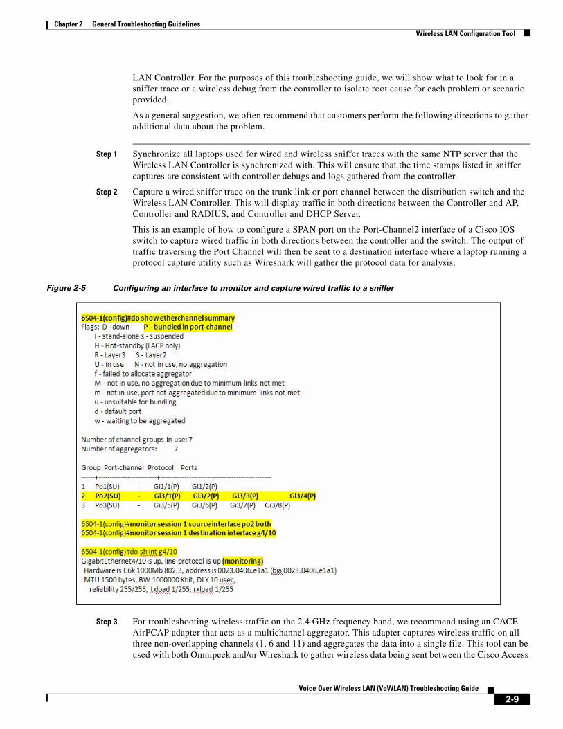
Step 2 Capture a wired sniffer trace on the trunk link or port channel between the distribution switch and the Wireless LAN Controller. This will display traffic in both directions between the Controller and AP, Controller and RADIUS, and Controller and DHCP Server.
This is an example of how to configure a SPAN port on the Port-Channel2 interface of a Cisco IOS switch to capture wired traffic in both directions between the controller and the switch. The output of traffic traversing the Port Channel will then be sent to a destination interface where a laptop running a protocol capture utility such as Wireshark will gather the protocol data for analysis.
Figure 2-5 Configuring an interface to monitor and capture wired traffic to a sniffer
Step 3 For troubleshooting wireless traffic on the 2.4 GHz frequency band, we recommend using an CACE AirPCAP adapter that acts as a multichannel aggregator. This adapter captures wireless traffic on all three non-overlapping channels (1, 6 and 11) and aggregates the data into a single file. This tool can be used with both Omnipeek and/or Wireshark to gather wireless data being sent between the Cisco Access
2-9Voice Over Wireless LAN (VoWLAN) Troubleshooting Guide

Chapter 2 General Troubleshooting GuidelinesTroubleshooting One-Way Audio
Point and the VoIP handset. For wireless troubleshooting on the 5 GHz frequency band, we suggest that you use one laptop per channel and use the tshark utility compiled in Wireshark or Omnipeek tools to combine both sniffer captures into a single file for review and analysis. For the purposes of this document, we will focus on troubleshooting as it pertains to deployments using the 792xG Series wireless IP phones.
Step 4 Once the laptops have been set up to capture both wired and wireless sniffer traces, you can gather the respective debugs and message logs from the controller(s). Depending upon the symptoms and potential problem experienced, the debugs that will need to be gathered will vary on a case by case basis. In most cases, it is prudent to gather the following debug for the client being tested, followed by any additional debugging needed.
(WiSM_4) >debug client ?
<MAC addr> MAC address
For details with regard to client debugging on the Cisco Wireless LAN Controller, please refer to the following document for details.
http://www.cisco.com/en/US/products/hw/wireless/ps430/products_tech_note09186a008091b08b.shtml
Troubleshooting One-Way AudioIt is important to understand that wireless communication occurs in a bi-directional manner. Uplink communication from the client to the AP is not always the same as downlink communication from the AP to the client. While an AP will send beacons downlink to the VoWLAN handset, most surveying tools will only display information as it pertains to downlink transmissions; therefore some problems are not easily detected using pre- or post-site survey tools. While a post site survey is vital after deploying the WLAN, a survey tool may not take into consideration the uplink signal being transmitted by the Cisco 792xG Series wireless IP phone in comparison to the downlink signal.
Most access points will often have a higher EIRP (Effective Isotropically Radiated Power), that is, the transmit power + the antenna gain. When comparing the EIRP to a VoWLAN handset, an AP on the 2.4 GHz band might be transmitting at its full power (100 mW), which is (20 dBm), and a Cisco 792xG Series wireless IP phone might be transmitting at only 40 or 50 mW. When this occurs, the IP phone will still hear the downlink frames sourced from the AP, but the AP will not hear the uplink frames from the wireless IP phone. This leads to Asymmetric Transmit as seen in Figure 2-6, and is typically the root cause of One-Way audio.
Figure 2-6 One-Way Audio Example
2-10Voice Over Wireless LAN (VoWLAN) Troubleshooting Guide

Chapter 2 General Troubleshooting GuidelinesTroubleshooting One-Way Audio
Note The regulatory requirements of 802.11g and 802.11a mean that clients do not have 100 mW transmit capabilities. Cisco highly recommends that the maximum configured transmit power on the access point be no higher than the maximum supported transmit rate on the IP phone. A phone with a slightly lower transmit power than the AP is better than the AP using less power than the phone, but having matching transmit powers lessens the likelihood of one-way audio.
In an effort to mitigate One-Way Audio, Cisco recommends three possible solutions:
• Enabling Dynamic Transmit Power Control (DTPC)
• Manually configuring AP Transmit Power Control
• Transmit Power Throttling (available in WLC release 6.0.188.0 or later)
By default, DTPC is enabled on the Wireless LAN Controller so that Cisco access points will advertise the transmit power for clients to learn. CCX compatible clients will then learn the AP transmit power and adjust their transmit power to match, ensuring that one-way audio does not occur. In later versions of the Cisco Wireless LAN Controller code, there is also a feature referred to as Transmit Power throttling. This allows systems engineers to throttle the maximum transmit on the access point to ensure that mechanisms such as the Coverage Hole Algorithm do not run and increase the transmit power beyond that of the 792xG Series wireless IP phone’s capabilities, 40/50 mW, respectively.
Note Non-Cisco voice clients must support a minimum of Cisco Compatible Extension v2 to use DTPC.
2-11Voice Over Wireless LAN (VoWLAN) Troubleshooting Guide

Chapter 2 General Troubleshooting GuidelinesTroubleshooting No Audio
Figure 2-7 Sniffer capture displaying One-Way Audio
As you can see in the sniffer trace, the RTP stream occurs in only a single direction, causing the user to hear audio in the downlink RTP stream. Unfortunately, due to the limited transmit capability of the wireless IP Phone, the voice client has roamed out of range with regard to its transmit capabilities, therefore the user on the other end cannot hear the mobile user.
In addition to the solutions provided above, it is also recommended that systems engineers consider the following possibilities:
• Check that the access point is enabled for ARP caching. When the Cisco Unified Wireless IP 792xG Series Phone is in power save mode or scanning, the access point can respond to the wireless IP phone, but only when ARP caching is enabled.
• Check the phone hardware to be sure the speaker is functioning properly.
• Check the volume settings in the Phone Settings menu.
Troubleshooting No AudioQ. Is the problem intermittent or does it occur consistently?
1. If so, try to use another phone to validate that the phone has signal.
2-12Voice Over Wireless LAN (VoWLAN) Troubleshooting Guide

Chapter 2 General Troubleshooting GuidelinesTroubleshooting Choppy Audio
2. If the issue is consistent across all phones, gather a wired and wireless sniffer trace and open a TAC case with Cisco Systems.
Scenario:
A 792xG Series wireless IP phone user places a call to another 792xG Series wireless IP phone user on the same wireless LAN across controller within the same mobility group. If the receiving phone rings and the audio is initially set up in both directions, this eliminates to need to look at the Cisco Unified Communication Manager as a potential point of failure. In a situation where no audio is reported, it is important to conclusively determine if both sides cannot hear to audio. Once the Systems Engineer has validated that no audio occurs, he or she should immediately take wired and wireless sniffer traces to isolate root cause. During analysis, it is important to validate using both wired and wireless sniffers that the RTP stream is getting sent and received in both directions between phones. From our experience, a loss of audio in both directions is often related to inadequate RF coverage or RF interference, and not QoS.
Troubleshooting Choppy Audio Q. Does the choppy audio occur everywhere, in a particular area, or when roaming?
A. Everywhere / Particular Area / Intra-Controller Roaming
1. Ensure that WLAN QoS is set to Platinum.
2. Ensure that the Platinum queue is set to use 802.1p tagging and is configured to a value of 6.
3. Ensure that the mls qos trust dscp command is enabled on all switch ports between the AP switch port and the Wireless LAN Controller. If a marking is lost in one direction, and the traffic is classified as best effort when reviewing a wired or wireless traces, you must review the switch configuration of every switch between the AP and the Wireless LAN Controller where the RTP stream traverse.
4. Use a Spectrum Analysis tool to isolate potential sources of RF interference or inadequate coverage.
Improper Roaming and Voice Quality or Lost Connection If users report that when engaged in an active phone call and walking from one location to another (roaming), the voice quality deteriorates or the connection is lost, you can use the following suggestions to identify the cause of the problem.
Voice Quality Deteriorates While Roaming • Check the RSSI on the destination access point to see if the signal strength is adequate. The next
access point should have an RSSI value of -67 dBm or greater.
• Check the site survey to determine if the channel overlap is adequate for the phone and the access point to hand off the call to the next access point before the signal is lost from the previous access point.
• Check to see if noise or interference in the coverage area is too great.
• Check that signal to noise ratio (SNR) levels are 25 dB or higher for acceptable voice quality.
2-13Voice Over Wireless LAN (VoWLAN) Troubleshooting Guide

Chapter 2 General Troubleshooting GuidelinesImproper Roaming and Voice Quality or Lost Connection
Delays in Voice Conversation While Roaming • Use the Site Survey Utility on the Cisco Unified Wireless IP Phone 792xG to see if there is another
acceptable access point as a roaming option. The next access point should have an RSSI value of 35 or greater to roam successfully.
• Check the Cisco Catalyst 45xx switch to see if it has the correct version of Supervisor (SUP) blades. The blades must be versions SUP2+ or higher to prevent roaming delays.
Phone Loses Connection with Cisco Unified Communications Manager While Roaming
Check for the following configuration or connectivity issues between the phone and the access point:
• The RF signal strength might be weak. Use the Site Survey Tool and check the RSSI value for the next access point.
• The next access point might not have connectivity to Cisco Unified Communications Manager.
• There might be an authentication type mismatch between the phone and the next access point.
• The access point might be in a different subnet from the previous access point. The Cisco Unified Wireless IP Phone 792xG is capable of Layer 2 roaming only.
Inter-Controller RoamingWhen roaming between controllers (Inter-Controller Roaming):
1. Validate whether the roam occurs at Layer 2 or Layer 3.
Note If running an older release than 5.2, make sure to configure symmetric tunneling using Step 2.
2. If the roam is at Layer 3, validate that the customer has implemented Symmetric Mobility on all Wireless LAN Controllers in the Mobility Group, utilizing the same tunneling type is outlined as a Mobility Group requirement.
To validate and configure tunneling on the Wireless LAN Controller, utilize the following commands:
(WiSM_4) >show mobility summary
(WiSM_4) >config mobility symmetric-tunneling enable
3. If the problem still occurs, you will need to capture a wired and wireless sniffer trace along with the following debugs on the WLC:
(WiSM_4) >debug client <MAC addr>
(WiSM_4) >debug mobility handoff enable
(WiSM_4) >debug cac packet enable
2-14Voice Over Wireless LAN (VoWLAN) Troubleshooting Guide

Chapter 2 General Troubleshooting GuidelinesImproper Roaming and Voice Quality or Lost Connection
There is the possibility during an inter-controller roam that a phone could be roaming to another controller where the maximum available bandwidth has already been consumed. Please see the section on troubleshooting Call Admissions Control for isolating whether or not this is the issue.
Note When a 792xG Series wireless IP phone makes an initial call and receives a “Status 202” error massager indicating that there is not enough available bandwidth, the phone will display “Network Busy”. In the situation where the phone roams to a secondary controller and receives the same error, the 792xG Series wireless IP phone will then make an attempt to roam back to any AP with an acceptable RSSI as measured in Site Survey Mode on the 792xG Series wireless IP phone.
Dropped CallsWhile dropped calls are not as common as Choppy or One-Way Audio, it is still something that the Cisco TAC deals with somewhat regularly. Most of the time, there is an RF problem within the customer’s environment that causes severe packet loss, causing the call to be dropped. This is often due to the interference or an inadequate site survey.
Another common occurrence is when the 792xG Series wireless IP phone needs to perform a DHCP renewal when it roams from AP1, WLC1 to AP2, WLC2. This commonly occurs when DHCP Required is enabled on the Wireless LAN Controller where the phone roamed to. DHCP Required is security feature that is mostly used for Guest access and forces the client to obtain an IP address from a DHCP server but occasionally breaks VoWLAN calls when enabled in the WLAN Configuration as seen in Figure 2-8.
Figure 2-8 DHCP Required configured in the WLAN profile
2-15Voice Over Wireless LAN (VoWLAN) Troubleshooting Guide

Chapter 2 General Troubleshooting GuidelinesImproper Roaming and Voice Quality or Lost Connection
While the following scenario should also be considered a possibility, it is not often the cause in environments where careful call capacity planning has been performed. Most of the time, the scenario outlined below has been discovered within the Healthcare vertical due to the need for an excessive number of wireless IP phones in use simultaneously in a single AP.
CAC Scenario:
792xG Series wireless IP phone is on AP1, Controller 1, and then roams to AP2 Controller 2. In a situation where there is not enough bandwidth available over the air on the Wireless LAN Controller where the phone is roaming to, a “Status code 202” error is sent to the phone resulting in a “Network Busy” message. The phone will then make an effort to roam to the AP with the strongest signal (usually the AP it was most recently connected to), but will perform a full Reauth. This scenario will also cause the call to be dropped.
Note As mentioned in the section on troubleshooting CAC, call capacity planning is essential and should be performed during an initial site survey and followed up by a post audit. The fundamental idea behind call capacity planning is to ensure that users do not saturate a single AP, causing CAC to deny access to network resources. The debug cac all enable command can be used to test and isolate if the scenario outlined above is the root cause of your problems. Please refer to the section on troubleshooting Call Admissions Control for details.
2-16Voice Over Wireless LAN (VoWLAN) Troubleshooting Guide

Voice Ov
C H A P T E R 3
Troubleshooting the 792xG Series Wireless IP PhoneUnderstanding the 792xG Series Wireless IP PhoneThe Cisco Unified Wireless IP Phone 792xG Series are 802.11 dual-band wireless devices that provide comprehensive voice communications in conjunction with the Cisco Unified Communications Manager and Cisco Aironet 802.11b/g and Cisco Aironet 802.11a Access Points (APs) within the Cisco Unified Wireless Network (CUWN). These phone models, like other network devices, must be configured and managed. The phones encode G.711a, G.711u, G.729a, G.729ab, G.722/iLBC, and decode G.711a, G711b, G.711u, G.729, G729a, G729b, and G729ab.
Understanding Basic OperationThe 792xG Series wireless IP phones are very similar to wired IP phones. If you are using a DHCP Server and Cisco Unified Communications Manager, the phone will obtain the address for the TFTP server through preconfigured options within the DHCP scope. It is important to make sure that the IP address of the publisher is configured in Option 150 or Option 66 in the DHCP scope options.
Please refer to Configuring Windows 2000 DHCP Server for Cisco Unified Call Manager available at the following URL for details:
http://www.cisco.com/en/US/products/sw/voicesw/ps556/products_tech_note09186a00800942f4.shtml
Basic Connectivity Problems
Symptom: No Association to Cisco Aironet Access Points
After the Greeting Message displays, if a phone continues to cycle through messages displaying on the phone screen, the phone is not associating with the access point properly. The phone cannot successfully start up unless it associates and authenticates with an access point.
Verifying Access Point Settings The Cisco Unified Wireless IP Phone 792xG Series must first authenticate and associate with an access point before it can obtain an IP address. The phone follows this start-up process with the access point:
1. Scans for an access point.
3-1er Wireless LAN (VoWLAN) Troubleshooting Guide

Chapter 3 Troubleshooting the 792xG Series Wireless IP PhoneVerifying Access Point Settings
2. Associates with an access point.
3. Authenticates using a preconfigured authentication method (if configured, can use LEAP, EAP-FAST, Auto (AKM), or others).
4. Obtains an IP address.
a. Check the SSID settings on the access point and on the phone to be sure the SSID matches.
b. Check the authentication type settings on the access point and on the phone to be sure authentication/encryption settings match.
Note If the message “No Service - IP Config Failed” displays, DHCP failed because the encryption between the access point and phone do not match.
If using static WEP, check the WEP key on the phone to be sure it matches the WEP key on the access point. Re-enter the WEP key on the phone to be sure it is correct.
Note If open authentication is set, the phone is able to associate to an access point, although the WEP keys are incorrect or mismatched.
Error Messages during Authentication
Authentication failed, No AP found
1. Check if the correct authentication method and related encryption settings are enabled on the AP.
2. Check that the correct SSID is configured on the phone.
3. Check that the correct username and password are configured when using LEAP, EAP-FAST or Auto (AKM) authentication.
4. If you are using a WPA Pre-Shared key or WPA2 Pre-Shared Key, check that you have the correct passphrase configured.
Note You might need to enter the username on the phone in the domain\username format when authenticating with a Windows domain.
EAP authentication failed
1. If you are using EAP, you might need to enter the EAP username on the phone in the domain\username format when authenticating with a Windows domain.
2. Check that the correct EAP username and password are entered on phone.
AP Error-cannot support all requested capabilities
1. On the access point, check that CKIP/CMIC is not enabled for the voice VLAN SSID. The Cisco Unified Wireless IP Phone 792xG Series does not support these features.
3-2Voice Over Wireless LAN (VoWLAN) Troubleshooting Guide

Chapter 3 Troubleshooting the 792xG Series Wireless IP PhoneVerifying Access Point Settings
Table 3-1 Common Status Messages
Message Description Possible Cause and Action
Network Busy The phone is unable to complete a call.
CAC is enabled and the available bandwidth (Medium Times) has been reached per AP/Channel, causing the call to be rejected by the Wireless LAN Controller.
Wait a few minutes and try the call again. If the problem persists, utilize the “debug cac all enable” to troubleshoot.
Leaving Service Area The phone is unable to place or receive calls. The no signal icon displays on the phone screen.
The phone cannot detect any beacons from the AP.
The phone is either out of range of an AP or the AP may have stopped beaconing unexpectedly.
Locating Network Services The phone is searching for an AP.
The phone is searching all beacons and scanning for a channel and SSID to use.
Authentication Failed The phone is unable to access the WLAN, and the main phone screen is not active.
The authentication server does not accept the security credentials.
Verify that the security mode and credentials are correct by viewing the Network profile.
Configuring IP The main phone screen is not active.
The phone is attempting to obtain network parameters such as its IP address, or the IP address of the gateway or router from the DHCP server.
If the phone is unable to retrieve the IP address, then check that the DHCP server is up and running.
Configuring CM List The main phone screen is not active.
The phone is downloading its configuration files from the TFTP server.
Wait a few minutes for the phone to download all of its configuration files.
3-3Voice Over Wireless LAN (VoWLAN) Troubleshooting Guide

Chapter 3 Troubleshooting the 792xG Series Wireless IP PhoneMonitoring the Cisco 792xG Series Wireless IP Phone
Note If you suspect the AP is the root cause, run the following diagnostic tests on the AP and submit the output to the Cisco TAC.
1. On AP console, enter:
AP1252-b5:c8>debug dot1 d0 trace print txev rcv beacons
2. From the Wireless LAN Controller:
(WiSM_4) >debug ap enable AP1252-b5:c8
(WiSM_4) >debug ap command 'debug dot11 d0 trace print txev rcv beacon' AP1252-b5:c8
Monitoring the Cisco 792xG Series Wireless IP PhoneOnce the phone has authenticated, associated and obtained a valid IP address, it will locate the Cisco Unified Communications Manager through preconfigured DHCP options, retrieve its configured directory number (DN), and download the latest version of firmware.
In order to monitor WLAN information, WLAN Statistics and Stream information pertaining to a VoWLAN call, use the following method.
https://[IP address]
The default username is “Admin” and the password is “Cisco.”
Note While monitoring is not in real-time, you can see somewhat consistent data by constantly refreshing the page.
For the purposes of understanding how to troubleshoot a call using the Web pages on the Cisco 792xG Series wireless IP phone, we have provided an example of a call made from a 7925G Series wireless IP phone with MAC 00:23:33:41:63:6F to another 7925G Series wireless IP phone with MAC 00:23:33:41:95:72.
As you can seen in Figure 3-1, the information provided allows the systems engineer to understand what the basic information is with regard to the call. The web pages displayed in Figure 3-1 and Figure 3-2 provide the BSSID, the AP where the 7925G IP phone is associated, the Tx Power (50 mW), Channel, RSSI, and Channel Utilization. These are all important values to understand with regard to your VoWLAN deployment.
3-4Voice Over Wireless LAN (VoWLAN) Troubleshooting Guide

Chapter 3 Troubleshooting the 792xG Series Wireless IP PhoneMonitoring the Cisco 792xG Series Wireless IP Phone
Figure 3-1 Cisco 7925 IP Phone 1
3-5Voice Over Wireless LAN (VoWLAN) Troubleshooting Guide

Chapter 3 Troubleshooting the 792xG Series Wireless IP PhoneMonitoring the Cisco 792xG Series Wireless IP Phone
Figure 3-2 Cisco 7925 IP Phone 2
If the RSSI, or channel utilization, is poor and does not adhere to design and deployment best practices as outlined in the VoWLAN Design Guide 4.1, please review the WLAN Statistics and the Stream Statistics web page to further troubleshoot the problem. Figure 3-3 and Figure 3-4 display the same call made between the 7925 IP phones at MAC 63:6F and 95:72 outlining what to look for on each of these pages.
3-6Voice Over Wireless LAN (VoWLAN) Troubleshooting Guide

Chapter 3 Troubleshooting the 792xG Series Wireless IP PhoneMonitoring the Cisco 792xG Series Wireless IP Phone
Figure 3-3 WLAN Statistics for IP Phone with MAC 00:23:33:41:63:6F
3-7Voice Over Wireless LAN (VoWLAN) Troubleshooting Guide

Chapter 3 Troubleshooting the 792xG Series Wireless IP PhoneMonitoring the Cisco 792xG Series Wireless IP Phone
Figure 3-4 WLAN Statistics for IP Phone with MAC 00:23:33:41:95:72
3-8Voice Over Wireless LAN (VoWLAN) Troubleshooting Guide

Chapter 3 Troubleshooting the 792xG Series Wireless IP PhoneMonitoring the Cisco 792xG Series Wireless IP Phone
When evaluating the WLAN statistics web page on the 792xG Series wireless IP phone, it is important to understand that Association and Authentication Timeout counters will usually increment when the 792xG Series wireless IP phone is out of range of an AP, has poor signal, or experiences severe packet loss. The “Authentication Rejects” counter is usually due to bad credentials or a problem on the Cisco ACS Server. While it is also important to compare the difference between the overall unicast frames transmitted and the Failed Retry counter, the Stream Statistics seen in Figure 3-5 and Figure 3-6 are far more valuable when troubleshooting the audio problems between IP phones on the WLAN.
Using Stream Statistics and Voice Quality Metrics To use the metrics for monitoring voice quality, utilize the Stream Statistics web page and document the typical scores under normal conditions and use the metrics as a baseline for comparison. To measure the voice quality of calls that are sent and received on the WLAN, the Cisco Unified IP Phones uses statistical metrics that are based on concealment events. The DSP plays concealment frames to mask frame loss in the voice packet stream.
• Concealment Ratio metrics - Show the ratio of concealment frames over total speech frames. An interval conceal ratio is calculated every 3 seconds.
• Concealed Second metrics - Show the number of seconds in which the DSP plays concealment frames due to lost frames. A severely “concealed second” is a second in which the DSP plays more than five percent concealment frames.
• MOS-LQK metrics - Use a numeric score to estimate the relative voice listening quality. The Cisco Unified IP Phone calculates the mean opinion score (MOS) for listening quality (LQK) based audible concealment events due to frame loss in the preceding 8 seconds and includes perceptual weighting factors such as codec type and frame size.
Note MOS LQK scores are produced by a Cisco proprietary algorithm, Cisco Voice Transmission Quality (CVTQ) index. Depending on the MOS LQK version number, these scores might be compliant with the International Telecommunications Union (ITU) standard P.564. This standard defines evaluation methods and performance accuracy targets that predict listening quality scores based on observation of actual network impairment. Concealment ratio and concealment seconds are primary measurements based on frame loss while MOS LQK scores project a “human-weighted” version of the same information on a scale from 5 (excellent) to 1 (bad) for measuring listening quality.
It is important to distinguish significant changes from random changes in metrics. Significant changes are scores that change about 0.2 MOS or greater and persist in calls that last longer than 30 seconds. MOS LQK scores can vary based on the codec that the Cisco Unified IP Phone uses. The following codecs provide these maximum MOS LQK scores under normal conditions with zero frame loss:
Table 3-2 WLAN Statistics Definitions
Item Description
Association Timeouts Number of failed association attempts due to timeout.
Authentication Timeouts Number of failed authentication attempts due to timeout.
Authentication Rejects Number of authentication attempts that the AP rejected.
Tx Unicast Frames Number of frames transmitted that are unicast traffic.
Failed Retries Counter Number of frames without acknowledgements.
3-9Voice Over Wireless LAN (VoWLAN) Troubleshooting Guide

Chapter 3 Troubleshooting the 792xG Series Wireless IP PhoneMonitoring the Cisco 792xG Series Wireless IP Phone
• G.711 codec gives 4.5 score
• G.729A/ AB gives 3.7 score
Note A Conceal Ratio of zero indicates that the IP network is delivering frames and packets on time with no loss.
Figure 3-5 Stream Statistics for IP Phone with MAC 00:23:33:41:63:6F
3-10Voice Over Wireless LAN (VoWLAN) Troubleshooting Guide

Chapter 3 Troubleshooting the 792xG Series Wireless IP PhoneMonitoring the Cisco 792xG Series Wireless IP Phone
Figure 3-6 Stream Statistics for IP Phone with MAC 00:23:33:41:95:72
3-11Voice Over Wireless LAN (VoWLAN) Troubleshooting Guide

Chapter 3 Troubleshooting the 792xG Series Wireless IP PhoneMonitoring the Cisco 792xG Series Wireless IP Phone
As you can see from Figure 3-5, the web page displays an active call on the 7925 IP phone ending in MAC 63:6F and provides you with an the Avg. MOS LQK score of 4.4270. Just as long as the 792xG Series wireless IP phone is able to see three or more APs and maintains an RSSI under -67 and a consistently good MOS score, there should not be any audio problems within the area where this call was made.
When troubleshooting VoWLAN issues, it is common for systems engineers to put the 792xG Series wireless IP phone on hold so Music On Hold (MoH) can be streamed via RTP to the wireless IP phone being tested. In most troubleshooting scenarios, we recommend that systems engineers initiate a call from a wired IP phone to the 792xG Series wireless IP phone that is experiencing problems.
Note If a call is initiated from a 792xG Series wireless IP phone 1 to 792xG Series wireless IP phone 2, the wireless IP phone that initiated the hold will not have a MOS score as seen in Figure 3-6. When the unicast stream between both phones is reinitiated, the 792xG Series wireless IP phone will then update its MOS score.
It is very important to constantly monitor and understand how RF changes in your environment and to take snapshots of random calls made from different areas. For new deployments, Cisco recommends that a baseline be created by taking daily, weekly and eventually monthly snapshots of VoIP calls made over the WLAN. This will allow you to create a baseline as mentioned previously and will also help systems administrators to understand which areas are potentially subject to RF problems or anomalies.
Additionally, be sure to understand the intricate details with regard to RRM, as it relates to the Coverage Hole Algorithm (CHA) and how that may inadvertently affect Transmit Power Control (TPC) within your Unified Wireless Network. Once you have had the opportunity to evaluate the information contained within the web page for each phone being tested, please ensure that the deployment is in accordance with Cisco VoWLAN design and deployment best practices. If you discover deviations, we strongly encourage you to perform a post Site Survey and audit how RF propagates within your WLAN.
Table 3-3 Stream Statistics Definitions
Item Description
Sender DSCP Must be EF.
Sender Report Time Internal time stamp indicating when this streaming statistics report was generated.
MOS LQK Score that is an objective estimate of the mean opinion score (MOS) for listening quality (LQK) that rates from 5 (excellent) to 1 (bad). This score is based on audible concealment events due to frame loss in the preceding 8-second interval of the voice stream.
3-12Voice Over Wireless LAN (VoWLAN) Troubleshooting Guide

Voice Ov
C H A P T E R 4
Troubleshooting QoSIntroductionAn important factor to consider when troubleshooting a Voice over Wireless LAN (VoWLAN) is the impact that Quality of Service (QoS) and Call Admissions Control plays on the quality of a call within the Cisco Unified Wireless Network (CUWN). QoS ensures that traffic is prioritized and trusted as traffic traverses the wired and wireless LAN.
With QoS, bandwidth can be managed more efficiently across LANs, including WLANs and WANs. QoS provides enhanced and reliable network service by doing the following:
• Supporting dedicated bandwidth for critical users and applications
• Controlling jitter and latency (required by real-time (RTP) traffic such as for voice)
• Managing and minimizing network congestion
• Shaping network traffic to smooth the traffic flow
• Setting network traffic priorities
In an effort to understand the technology from a design and deployment perspective, we would strongly encourage you to read and understand WLAN Quality of Service as described in the VoWLAN Design Guide 4.1, which can be located here.
https://www.cisco.com/en/US/docs/solutions/Enterprise/Mobility/vowlan/41dg/vowlan_ch2.html
Troubleshooting QoSWhen troubleshooting QoS, there are basic criteria that you need to understand and adhere to when deploying a VoWLAN when using the Cisco Unified Wireless Network. The following are criteria that need to be met:
• Ensure that WMM is configured on the Wireless LAN Controller.
• Ensure that RTP packets have the proper QoS markings.
• Select the “Platinum” QoS profile for the VoWLAN when using Cisco Unified Wireless LAN Controller and configure the 802.1p tag to “6”.
• Enable Differentiated Services Code Point (DSCP) preservation on the Cisco IOS switch (mls qos trust dscp) and/or use a QoS Service Policy to allocate the appropriate level of priority.
– Option 1 - If you choose to create a QoS Service Policy on an interface between the AP and the WLAN, ensure that the voice traffic (RTP) has the highest priority as follows:
4-1er Wireless LAN (VoWLAN) Troubleshooting Guide

Chapter 4 Troubleshooting QoSTroubleshooting QoS
RTP (DSCP = EF) to COS = 6
SCCP (DSCP = CS3) to COS = 4
– Option 2 - If you choose to implement AutoQoS, ensure that the switches are using the same version of IOS code. If the IOS switches are different, or the IOS code varies from switch to switch, understand how AutoQoS is configured from version to version. AutoQoS can actually cause more harm than good if QoS profiles are not consistent between switches. In most cases, DSCP preservation is the best way to ensure that RTP traffic is forwarded with the aspirate markings across the LAN.
Figure 4-1 Class Map, Policy-Map and Service Policy Example
Step 1: Classify Traffic6504-2(config)#class-map match-all RTP6504-2(config-cmap)#match ip dscp ef6504-2(config)#class-map match-all SCCP6504-2(config-cmap)#match ip dscp cs3
Step 2: Assign the Classified Traffic to a Policy Map6504-2(config)#policy-map VOICE6504-2(config-pmap)#class RTP6504-2(config-pmap-c)#set cos 66504-2(config-pmap)#class SCCP6504-2(config-pmap-c)#set cos 4
Note If this is a L3 link, it is important to utilize the “set dscp ef” and “set dscp cs3” parameters, rather than the CoS. A L2 link will mark according to CoS, whereas a L3 link will only evaluate L3 markings. (i.e., CoS = L2 / DSCP = L3).
Step 3: Assign the Policy Map to an interface using the Service-Policy command.6504-2(config)#int g4/1 6504-2(config-if)#Service-policy output VOICE6504-2(config-if)#Service-policy input VOICE
Figure 4-2 DSCP Preservation Example
6504-2(config)#int g4/1 6504-2(config-if)#mls qos trust dscp
As you can see from Figure 4-1 and Figure 4-2, while classifying traffic might seem like a good idea, it is more important to keep the VoWLAN deployment as simple as possible. Since the 792xG Series wireless IP phone will send RTP traffic over the WLAN with the appropriate markings, we recommend that Systems Engineers create a baseline for the VoWLAN by preserving the existing markings on each interface between the AP and the WLC. This will ensure that DSCP is trusted in both directions as the RTP streams traverse the switched network.
4-2Voice Over Wireless LAN (VoWLAN) Troubleshooting Guide
Chapter 4 Troubleshooting QoSTroubleshooting QoS
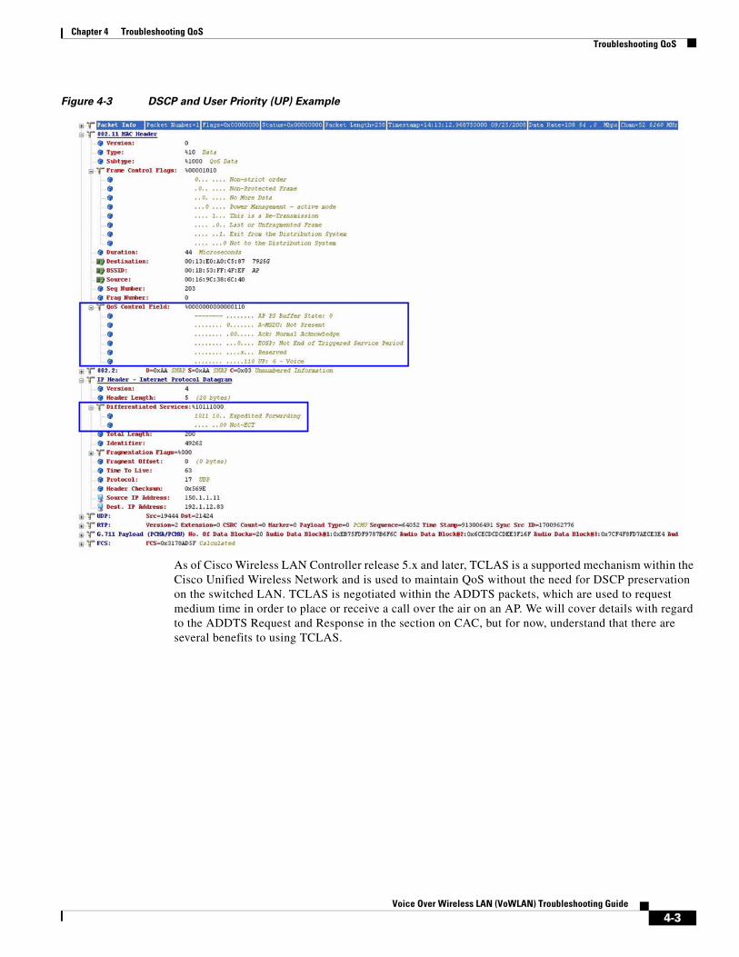
Figure 4-3 DSCP and User Priority (UP) Example
As of Cisco Wireless LAN Controller release 5.x and later, TCLAS is a supported mechanism within the Cisco Unified Wireless Network and is used to maintain QoS without the need for DSCP preservation on the switched LAN. TCLAS is negotiated within the ADDTS packets, which are used to request medium time in order to place or receive a call over the air on an AP. We will cover details with regard to the ADDTS Request and Response in the section on CAC, but for now, understand that there are several benefits to using TCLAS.
4-3Voice Over Wireless LAN (VoWLAN) Troubleshooting Guide

Chapter 4 Troubleshooting QoSTroubleshooting QoS
4-4Voice Over Wireless LAN (VoWLAN) Troubleshooting Guide

Voice Ov
C H A P T E R 5
Troubleshooting Call Admissions ControlVoWLAN Call Capacity An important factor to consider in a Voice Over Wireless LAN (VoWLAN) is Call Capacity Planning. The number of simultaneous VoWLAN calls that can be supported on a given AP and channel is very important to understand. This value can vary depending upon the static parameters configured on the Wireless LAN Controller or IP Phone or the variations within the RF environment.
For example, the VoWLAN maximum capacity for a Cisco Unified IP Phone 792xG using the Cisco Unified Wireless Network with Load-Based CAC is expected to allow a greater number of calls than with Static CAC in an environment that has ideal RF characteristics. For example, you may get 14 VoWLAN calls per 2.4 GHz channel and 20 simultaneous VoWLAN calls per 5 GHz channel. These capacity values are based on assuming no competing high priority WLAN traffic and normal background noise that adhere to the appropriate best practice recommendations as outlined in the section of RF Design Validation.
Note Because the 5 GHz spectrum generally features less noise and interference, there can be greater capacity with the higher carrier frequency implementation. The additional non-overlapping channels available in the 5 GHz spectrum also provides a great deal more call capacity for a given area.
TSPEC Admissions ControlTraffic Specification (TSpec) allows an 802.11e client to signal its traffic requirements to the AP. In the 802.11e MAC definition, two mechanisms provide prioritized access. These are the contention-based EDCF option and the controlled access option provided by the transmit opportunity (TXOP). When describing TSPEC features where a client can specify its traffic characteristics, it is easy to assume that this would automatically result in the use of the controlled access mechanism, and have the client granted a specific TXOP to match the TSPEC request. However, this does not have to be the case; a TSpec request can be used to control the use of the various ACs in EDCF. Before a client can send traffic of a certain priority type, it must have requested to do so via the TSpec mechanism. For example, a WLAN client device wanting to use the voice AC must first make a request for use of that AC. Whether or not AC use is controlled by TSpec requests is configurable with voice and video ACs controlled by TSpec requests, and best-effort and background ACs can be open for use without a TSpec request. The use of EDCF ACs, rather than the 802.11e Hybrid Coordinated Channel Access (HCCA), to meet TSpec requests is possible in many cases because the traffic parameters are sufficiently simple to allow them to be met by allocating capacity, rather than creating a specific TXOP to meet the application requirements.
5-1er Wireless LAN (VoWLAN) Troubleshooting Guide

Chapter 5 Troubleshooting Call Admissions ControlAdd Traffic Stream
Add Traffic StreamThe Add Traffic Stream (ADDTS) function is how a WLAN client performs an admissions request to an AP. The 792x client signals its TSPEC admission request to the AP in one of two forms:
ADDTS Action Frame-this occurs when a phone call is originated or terminated by the 792x client associated to the AP. The ADDTS contains TSpec and might contain a traffic stream rate set (TSRS) IE (Cisco Compatible Extensions v4 clients).
Association and re-association messageThe association message might contain one or more TSpecs and one TSRS IE if the STA wants to establish the traffic stream as part of the association. The re-association message might contain one or more TSPECs and one TSRS IE if an STA roams to another AP.
The ADDTS contains the TSpec element that describes the traffic request. See Figure 5-1 and Figure 5-2 for examples of an ADDTS request and response between a Cisco Unified Wireless IP Phone 792xG WLAN handset and a Cisco AP. Apart from key data describing the traffic requirements, such as data rates and frame sizes, the TSpec element also tells the AP the minimum physical rate that the client device will use. This allows the calculation of how much time that station can potentially consume in sending and receiving in this TSpec, and therefore allowing the AP to calculate whether it has the resources to meet the TSpec. TSpec admission control is used by the WLAN client (target clients are VoIP handsets) when a call is initiated and during a roam request. During a roam, the TSpec request is appended to the re-association request.
5-2Voice Over Wireless LAN (VoWLAN) Troubleshooting Guide

Chapter 5 Troubleshooting Call Admissions ControlAdd Traffic Stream
Figure 5-1 ADDTS Request Decode
5-3Voice Over Wireless LAN (VoWLAN) Troubleshooting Guide

Chapter 5 Troubleshooting Call Admissions ControlUnderstanding Static CAC
Figure 5-2 ADDTS Response Decode
Understanding Static CACAs mentioned previously, there are two types of Admissions Control. Static CAC is based on a percentage of the total Medium Times available and is measure in increments of 32 microseconds. In this section, we will cover how to configure Static and Load-Based CAC and also how to debug it.
Please see Figure 5-3 and Figure 5-4 for an example using default parameters.
5-4Voice Over Wireless LAN (VoWLAN) Troubleshooting Guide

Chapter 5 Troubleshooting Call Admissions ControlUnderstanding Static CAC
Figure 5-3 Static CAC Configuration Example
Figure 5-4 Load-Based CAC Configuration Example
5-5Voice Over Wireless LAN (VoWLAN) Troubleshooting Guide

Chapter 5 Troubleshooting Call Admissions ControlDebugging Static CAC
In an effort to understand how Static CAC works with regard to allocating bandwidth, you need to understand the basics with regard to the math. In circumstances where the 792xG Series wireless IP phone uses a G.711 codec and the Cisco Wireless LAN Controller is configured to utilize data rates are in accordance with Cisco VoWLAN best practices, a single uni-directional RTP stream will utilize 538 Medium Times, or 1076 Medium Times per call.
An AP supports a total of 31,250 Medium Times, which is defined in the 802.11e standard and is an RF measurement used by TSPec for Admissions Control. In a Static CAC configuration, the Medium Times are multiplied times the Max RF bandwidth and Reserved Roaming Bandwidth and divided by the number of calls that are made against a single Access Point during Association.
For example, if Static CAC has been configured using default settings, codecs and data rates in accordance with VoWLAN Design and Deployment Best practices, the formula to calculate the total number of calls is as follows:
If each uni-directional RTP stream utilizes 538 Medium Times, you would multiply that times 2 to determine to the total MT's per call. In this example, it is 1076 MTs per call.
– 31250 (Medium Times) * Configured Max RF Bandwidth \ 100 = (maxBw)
– (maxBw) * Configured Reserved Roaming Bandwidth \ 100 = (roamBw)
– The (roamBw) should then be subtracted from the (maxBw), and then divided by 1076 yielding the total number of calls allowed on the VoWLAN.
Note By default the Max RF Bandwidth is 75% and Reserved Roaming Bandwidth is 6%.
Debugging Static CACScenario:
In this scenario, the Static CAC configuration is as follows:
• Max RF Bandwidth: 40%
• Reserved Roaming Bandwidth: 6%
Using the Formula outlined above, we can conclude the following:
• 31250 (Medium Times) * 40% \ 100 = 12500 (maxBw)
• 12500 (maxBw) * 6% \ 100 = 750 (roamBw)
• 12500 (maxBw) - 750 (roamBw) = 11750 (avail_Bw) \ 1076 (bw_req) = 10.92 calls.
From the example, we can see that based on a Max RF Bandwidth of 40% and Reserved Roaming Bandwidth of 6%, the VoWLAN will yield 10 calls with the 11th call being denied access to the WLAN. Please refer to Figure 5-5 through Figure 5-9, which outline how Static CAC can be debugged.
5-6Voice Over Wireless LAN (VoWLAN) Troubleshooting Guide

Chapter 5 Troubleshooting Call Admissions ControlDebugging Static CAC
Figure 5-5 Debugging Static CAC Example (part 1)
(WiSM_4) >show ap summary
Number of APs.................................... 1
Global AP User Name.............................. Not ConfiguredGlobal AP Dot1x User Name........................ Not Configured
AP Name Slots AP Model Ethernet MAC Location Port Country Priority------------------ ----- ------------------- ----------------- ---------------- ---- ------- ------AP1252-b5:c8 2 AIR-LAP1252AG-A-K9 00:23:04:eb:b5:c8 default location LAG US 1
(WiSM-4) >show client summary
Number of Clients................................ 27
MAC Address AP Name Status WLAN Auth Protocol Port Wired----------------- ----------------- ------------- ---- ---- -------- ---- -----
00:13:02:03:fb:a3 AP1252-b5:c8 Probing N/A No 802.11b 29 No00:18:ba:78:cb:fa AP1252-b5:c8 Associated 1 Yes 802.11a 29 No00:1a:a1:92:5e:f7 AP1252-b5:c8 Associated 1 Yes 802.11a 29 No00:1a:a1:92:62:6f AP1252-b5:c8 Associated 1 Yes 802.11a 29 No00:1a:a1:92:63:fe AP1252-b5:c8 Associated 1 Yes 802.11a 29 No00:1a:a1:92:66:17 AP1252-b5:c8 Associated 1 Yes 802.11a 29 No00:1a:a1:92:b5:9c AP1252-b5:c8 Associated 1 Yes 802.11a 29 No00:1a:a1:92:b9:5c AP1252-b5:c8 Associated 1 Yes 802.11a 29 No00:1a:a1:92:ba:82 AP1252-b5:c8 Associated 1 Yes 802.11a 29 No00:1a:a1:92:c1:d8 AP1252-b5:c8 Associated 1 Yes 802.11a 29 No00:1a:a1:92:c4:1e AP1252-b5:c8 Associated 1 Yes 802.11a 29 No00:1a:a1:92:c4:d5 AP1252-b5:c8 Associated 1 Yes 802.11a 29 No00:1a:a1:92:c6:07 AP1252-b5:c8 Associated 1 Yes 802.11a 29 No00:1a:a1:92:c6:13 AP1252-b5:c8 Associated 1 Yes 802.11a 29 No00:1a:a1:92:c6:f1 AP1252-b5:c8 Associated 1 Yes 802.11a 29 No00:1a:a1:92:c7:03 AP1252-b5:c8 Associated 1 Yes 802.11a 29 No00:1b:d4:54:52:60 AP1252-b5:c8 Associated 1 Yes 802.11a 29 No00:1e:7a:ba:d0:0e AP1252-b5:c8 Associated 1 Yes 802.11a 29 No00:1e:7a:ba:d7:ac AP1252-b5:c8 Associated 1 Yes 802.11a 29 No00:1e:7a:ba:dc:92 AP1252-b5:c8 Associated 1 Yes 802.11a 29 No !! Call 11 !!00:1f:6c:7a:12:c1 AP1252-b5:c8 Associated 1 Yes 802.11a 29 No00:1f:9e:8b:29:50 AP1252-b5:c8 Associated 1 Yes 802.11a 29 No00:22:90:fd:a6:31 AP1252-b5:c8 Associated 1 Yes 802.11a 29 No00:22:90:fd:a9:6a AP1252-b5:c8 Associated 1 Yes 802.11a 29 No !! First Call !!00:22:90:fd:a9:b5 AP1252-b5:c8 Associated 1 Yes 802.11a 29 No00:22:90:fd:a9:e8 AP1252-b5:c8 Associated 1 Yes 802.11a 29 No00:22:90:fd:aa:0f AP1252-b5:c8 Associated 1 Yes 802.11a 29 No00:23:33:41:63:6f AP1252-b5:c8 Associated 1 Yes 802.11a 29 No
[BEGIN SNIP]
5-7Voice Over Wireless LAN (VoWLAN) Troubleshooting Guide

Chapter 5 Troubleshooting Call Admissions ControlDebugging Static CAC
Figure 5-6 Debugging Static CAC Example (part 2)
(WiSM-4) >show ap stats 802.11a AP1252-b5:c8
Number Of Slots.................................. 2 AP Name.......................................... AP1252-b5:c8MAC Address...................................... 00:23:04:eb:b5:c8Radio Type....................................... RADIO_TYPE_80211aStats Information Number of Users................................ 26 TxFragmentCount................................ 4272 MulticastTxFrameCnt............................ 113 FailedCount.................................... 2 RetryCount..................................... 657 MultipleRetryCount............................. 0 FrameDuplicateCount............................ 1 RtsSuccessCount................................ 1 RtsFailureCount................................ 0 AckFailureCount................................ 657 RxFragmentCount................................ 0 MulticastRxFrameCnt............................ 0 FcsErrorCount.................................. 201 TxFrameCount................................... 11774 WepUndecryptableCount.......................... 0 TxFramesDropped................................ 0
Call Admission Control (CAC) Stats Voice Bandwidth in use(% of config bw)......... 0 Total channel MT free........................ 0 Total voice MT free.......................... 0 Na Direct.................................... 0 Na Roam...................................... 0 Video Bandwidth in use(% of config bw)......... 0 Total num of voice calls in progress........... 0 Num of roaming voice calls in progress......... 0 Total Num of voice calls since AP joined....... 0 Total Num of roaming calls since AP joined..... 0 Total Num of exp bw requests received.......... 0 Total Num of exp bw requests admitted.......... 0 Num of voice calls rejected since AP joined.... 0 Num of roam calls rejected since AP joined..... 0 Num of calls rejected due to insufficent bw.... 0 Num of calls rejected due to invalid params.... 0 Num of calls rejected due to PHY rate.......... 0 Num of calls rejected due to QoS policy........ 0
5-8Voice Over Wireless LAN (VoWLAN) Troubleshooting Guide

Chapter 5 Troubleshooting Call Admissions ControlDebugging Static CAC
Figure 5-7 Debugging Static CAC Example (part 3)
For the purposes of this troubleshooting guide the length of the debug was reduced, however, when issuing the “debug cac all enable” command on the Cisco Wireless LAN Controller, you will noticed that as additional calls are made one after another on the same AP, the available bandwidth (Medium Times) decrements by 1076 per call until the Medium Times (availBw) are exhausted. Once exhausted, the AP will send the following error seen in the output below. The will result in a “Network Busy” message on the 792xG Series wireless IP phone.
(WiSM-4) >debug cac all enable
*Dec 12 01:19:45.106 2009: Call Access Control accounting TSPEC to MAP AP1252-b5:c8 MAC 00:22:90:93:4c:60*Dec 12 01:19:45.106 2009: 00:22:90:fd:a9:6a Allocating voice bw for ms on AP AP1252-b5:c8 00:22:90:93:4c:60 slotId 1tid = 6 maxBw = 12500 bw_req = 1076 totalVoiceBwAlloc = 1076 *Dec 12 01:19:45.106 2009: 00:22:90:fd:a9:6a sending ADD TS to AP 00:22:90:93:4c:60 slotId 1, for client 00:22:90:FD:A9:6A tid = 6 up = 6, upsd = 1, bw = 1076
!! --- First Call --- !!
*Dec 12 01:19:45.106 2009: 00:22:90:fd:a9:6a Sending Successfull ADD TS resp to mobile on AP 00:22:90:93:4c:60 slotId 1
*Dec 12 01:19:45.106 2009: 00:22:90:93:4c:60 AP slotId 1 voiceBw = 12500 videoBw = 0 voiceBwAlloc = 1076 videoBwAlloc = 0 availBw = 11750
*Dec 12 01:19:45.106 2009: 00:22:90:fd:a9:e8 ADD TS from mobile on AP 00:22:90:93:4c:60 slotId 1 up = 6, tid = 6, upsd = 1, mediumTime = 1076, TSRSIE No
*Dec 12 01:19:45.106 2009: 00:22:90:fd:a9:e8 up=6 tsid=6 direc=3NomMsduSize=208MaxMsduSize=208MinServIntvl=0MaxServIntvl=0InactIntval=0MinDataRate=83200MeanDataRate=83200PeakDataRate=83200MinPhyRate=12000000SBA=0x2999MediumTime=1076
!! --- End First Call --- !!
[END SNIP]
5-9Voice Over Wireless LAN (VoWLAN) Troubleshooting Guide

Chapter 5 Troubleshooting Call Admissions ControlDebugging Static CAC
Figure 5-8 Debugging Static CAC Example (part 4)
As you can see below, the bandwidth required is 1076 (bw_req = 1076) and the Maximum Bandwidth is 12500 (maxBw = 12500) Since the bandwidth allocated has reached 10760 (bwAloc = 10760), that leaves 1740 Medium Times, of which 750 (roamBw = 750) has been allocated to Reserved Roaming Bandwidth, resulting in 990 Medium Times remaining. Finally, this results in insufficient bandwidth and thus causes the following output to be seen in the “debug cac all enable” on the Cisco Wireless LAN Controller.
[SNIP CONT']
!! --- Eleventh Call --- !!
*Dec 12 01:19:45.106 2009: 00:1e:7a:ba:dc:92 ADD TS from mobile on AP 00:22:90:93:4c:60 slotId 1 up = 6, tid = 6, upsd = 1, mediumTime = 1076, TSRSIE No
Wed Jul 22 06:13:14 2009: 00:1e:7a:ba:dc:92 up=6 tsid=6 direc=3NomMsduSize=208MaxMsduSize=208MinServIntvl=0MaxServIntvl=0InactIntval=0MinDataRate=83200MeanDataRate=83200PeakDataRate=83200MinPhyRate=12000000SBA=0x2999MediumTime=1076*Dec 12 01:19:45.106 2009: Max stream Size is 168000*Dec 12 01:19:45.106 2009: 2009: Max streams number is 2
5-10Voice Over Wireless LAN (VoWLAN) Troubleshooting Guide

Chapter 5 Troubleshooting Call Admissions ControlDebugging Static CAC
Figure 5-9 Debugging Static CAC Example (part 5)
*Dec 12 01:19:45.106 2009: 00:1e:7a:ba:dc:92 Can not allocate bw for ms on AP 00:22:90:93:4c:60 slotId 1 ac = 2, assoc = 0, bw_req = 1076, maxBw = 12500, bwAloc = 10760, roamBw = 750*Dec 12 01:19:45.106 2009: 00:1e:7a:ba:dc:92 TSPEC from mobile (up = 6), Not enough bandwidth.*Dec 12 01:19:45.106 2009: 00:1e:7a:ba:dc:92 Sending Failed ADD TS resp to mobile on AP 00:22:90:93:4c:60 slotId 1
!! --- End of Eleventh Call --- !!
(WiSM-4) >show p stats 802.11a AP1252-b5:c8
Number Of Slots.................................. 2 AP Name.......................................... AP1252-b5:c8MAC Address...................................... 00:23:04:eb:b5:c8It coulRadio Type....................................... RADIO_TYPE_80211a
Stats Information Number of Users................................ 26 TxFragmentCount................................ 4272 MulticastTxFrameCnt............................ 113 FailedCount.................................... 2 RetryCount..................................... 657 MultipleRetryCount............................. 0 FrameDuplicateCount............................ 1 RtsSuccessCount................................ 1shes all that RtsFailureCount................................ 0 AckFailureCount................................ 657 RxFragmentCount................................ 0 MulticastRxFrameCnt............................ 0 FcsErrorCount.................................. 201 TxFrameCount................................... 11774 WepUndecryptableCount.......................... 0 TxFramesDropped................................ 0
Call Admission Control (CAC) Stats Voice Bandwidth in use(% of config bw)......... 86 Total channel MT free........................ 0 Total voice MT free.......................... 0 Na Direct.................................... 0 Na Roam...................................... 0Video Bandwidth in use(% of config bw)......... 0
Total num of voice calls in progress........... 10
Num of roaming voice calls in progress......... 0 Total Num of voice calls since AP joined....... 10 !! Active VoWLAN calls !! Total Num of roaming calls since AP joined..... 0 Total Num of exp bw requests received.......... 0 Total Num of exp bw requests admitted.......... 0 Num of voice calls rejected since AP joined.... 1 !! The 11th Call was denied as seen above !! Num of roam calls rejected since AP joined..... 0 Num of calls rejected due to insufficent bw.... 1 !! Rejected Call !! Num of calls rejected due to invalid params.... 0 Num of calls rejected due to PHY rate.......... 0 Num of calls rejected due to QoS policy........ 0
(WiSM-4) >debug disable-all
[SNIP CONT' END]
5-11Voice Over Wireless LAN (VoWLAN) Troubleshooting Guide

Chapter 5 Troubleshooting Call Admissions ControlDebugging LBCAC
Debugging LBCACLoad-Based CAC on the other hand is significantly more difficult to debug. LBCAC is dynamic with regard to the algorithm used to decrement Medium Times from the total that is available. LBCAC takes into consideration different metrics, such as load, Co-channel interference, SNR, etc. and will therefore yield different results when tested. From our experience, it is very difficult to yield consistent results as RF fluctuates and changes within the given environment. Results tend to vary from one cell area to another and even in cell areas that yield the same signal strength.
At Cisco, we have seen consistent results with regard to LBCAC tests performed in a shield room, however, those results are only an indication to us of how the 792xG Series wireless IP phone might perform under the most ideal circumstances. In the real world, results will vary significantly. It's important to understand that RF is dynamic in nature and while a single AP might allow 15 calls on Tuesday, it may yield more or less the next day as environmental circumstances change. Overall, LBCAC does yield a greater number of calls per AP due to the mechanisms it uses to decrement the available Medium Times. Remember, with Static CAC, a bi-directional RTP stream decrements a fixed value of 1076 MT's from the available bandwidth, while LBCAC will factor in other variables and might only decrement 700 or 800 medium times per call. The only way to conclusively determine why results in LBCAC changes so dramatically in a single area is to take wireless sniffer traces and perform Spectrum Analysis within a given environment and utilize that data to isolate root cause. If call capacity is of vital concern and your WLAN is not yielding the expected results, it's ideal to ensure that your VoWLAN deployment adheres to all of the outlined VoWLAN Design and Deployment Best practices and each phone sees at least 3 Access Points with an acceptable RSSI.
Chapter SummaryIt’s important to understand that the purpose of TSpec admission control is not to deny clients access to the WLAN; it’s to protect the existing VoWLAN calls and to ensure that quality does no degrade. Without the implementation of CAC, any additional calls above and beyond the available bandwidth available will causes on overall degradation of quality to all VoWLAN users.net.
5-12Voice Over Wireless LAN (VoWLAN) Troubleshooting Guide

Voice Ov
C H A P T E R 6
Troubleshooting VoWLAN using OmniPeekCapturing Data for Wireless AnalysisTo troubleshoot VoWLAN, we must first capture the wireless data carrying the VoWLAN information. Capturing data for wireless analysis can be broken down into two main categories: portable and distributed. The type of data captured and retained varies depending on the intended use of the data. OmniPeek is designed for troubleshooting and root cause analysis, therefore it captures and stores every 802.11 packet.
Portable AnalysisPortable analysis requires that the analyst be present at the source of data collection with the appropriate hardware and software to perform the analysis. Portable analysis using OmniPeek is typically done with a laptop computer running OmniPeek Professional or OmniPeek Enterprise, using one or more supported wireless adapters.
Distributed AnalysisDistributed analysis allows the analyst to collect data from remote locations and analyze the data locally. This eliminates costly visits to remote locations for portable analysis. WildPackets supports two primary methods for distributed analysis.
AP Remote Adapters
The AP Remote Adapter provides connectivity between OmniPeek and Cisco LWAPP/CAPWAPs over a wired network. Using the control software for the managed wireless switch, first choose which access point(s) to use as packet capture devices. Once selected, set the channel to be used and then specify the IP address where OmniPeek is running. This is the IP address that the AP(s) will send the packets to. Now configure OmniPeek to receive the packet stream by starting a new capture and setting the Cisco Remote Adapter properties in the Capture Options dialog box as shown below.
6-1er Wireless LAN (VoWLAN) Troubleshooting Guide

Chapter 6 Troubleshooting VoWLAN using OmniPeekCapturing Data for Wireless Analysis
Figure 6-1 Capture Options
Name: Provide a unique name for the remote adapter.
IP Address: Providing an IP address means OmniPeek will accept only packets from that IP address. If this field is left blank, OmniPeek will accept packets from any AP that sends packets to the IP address of the computer running OmniPeek.
Set any other capture parameters and click OK. Then click Start once the OmniPeek capture screen is shown.
For a video guide of this procedure, see http://www.wildpackets.com/ciscoapgrabber_video.
OmniEngines
OmniEngines provide data capture and analysis 24 hours a day without requiring ongoing monitoring by the analyst. OmniEngines are Windows software or Linux appliances (Omnipliances) that are designed for continuous, remote operation. For wireless analysis, supported wireless adapters need to be added to enable wireless capture. OmniEngines are remotely controlled using OmniPeek as a console. Use the OmniPeek UI to configure and start the capture on the OmniEngine. All data is then captured, analyzed and stored by the OmniEngine, with no data sent over the wired network. All results from the OmniEngine analysis can be viewed using the OmniPeek console.
6-2Voice Over Wireless LAN (VoWLAN) Troubleshooting Guide
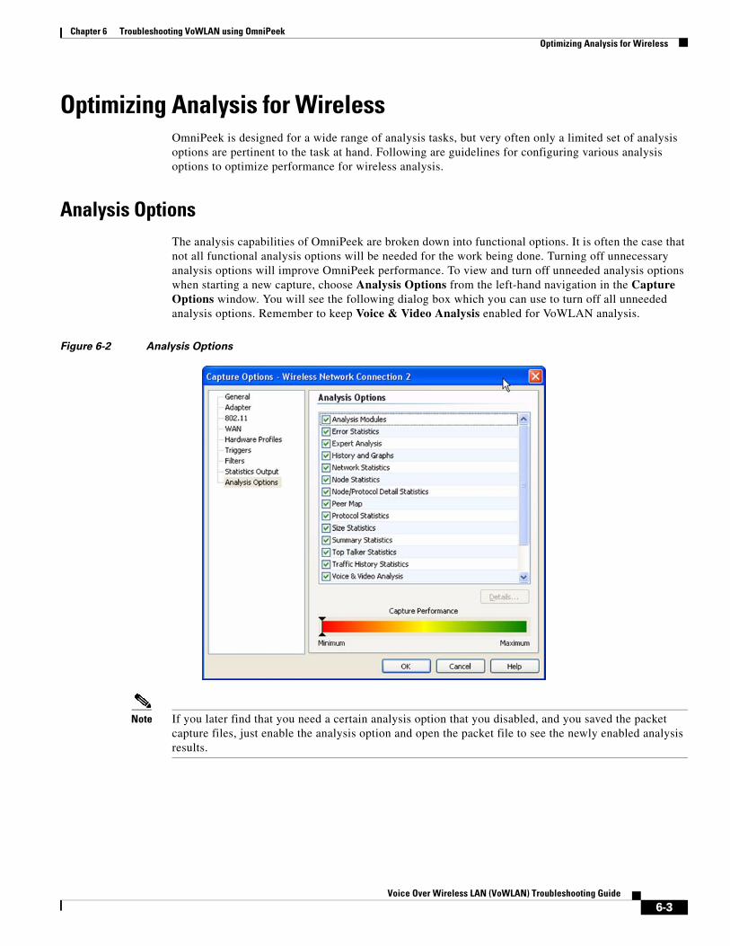
Chapter 6 Troubleshooting VoWLAN using OmniPeekOptimizing Analysis for Wireless
Optimizing Analysis for WirelessOmniPeek is designed for a wide range of analysis tasks, but very often only a limited set of analysis options are pertinent to the task at hand. Following are guidelines for configuring various analysis options to optimize performance for wireless analysis.
Analysis OptionsThe analysis capabilities of OmniPeek are broken down into functional options. It is often the case that not all functional analysis options will be needed for the work being done. Turning off unnecessary analysis options will improve OmniPeek performance. To view and turn off unneeded analysis options when starting a new capture, choose Analysis Options from the left-hand navigation in the Capture Options window. You will see the following dialog box which you can use to turn off all unneeded analysis options. Remember to keep Voice & Video Analysis enabled for VoWLAN analysis.
Figure 6-2 Analysis Options
Note If you later find that you need a certain analysis option that you disabled, and you saved the packet capture files, just enable the analysis option and open the packet file to see the newly enabled analysis results.
6-3Voice Over Wireless LAN (VoWLAN) Troubleshooting Guide

Chapter 6 Troubleshooting VoWLAN using OmniPeekOptimizing Analysis for Wireless
Expert Event AnalysisIn addition to functional analysis options, OmniPeek continually monitors the network for Expert events, network anomalies, and suboptimal performance at all layers of the network, from application to physical. It also shows network events associated with wireless-specific anomalies and VoIP calls. Each individual Expert event can be enabled or disabled separately. It is important to review the Expert events to ensure that events you want to analyze are enabled. Once a capture is started, choose any one of the Expert Views from the left-hand navigation of the main Capture Window, and then click on the Expert EventFinder Settings icon. The Expert EventFinder Settings dialog box will appear, allowing each individual Expert event to be configured and enabled or disabled. Pay special attention to the VoIP and Wireless Expert Events, as these can be extremely useful in identifying VoWLAN issues before they become serious problems.
Figure 6-3 Expert Event Analysis
Multichannel AnalysisMultichannel analysis allows multiple, simultaneous captures on unique wireless channels with all captured packets analyzed as if it is a single capture. This is extremely useful for analyzing situations where users are roaming from channel to channel, or when it is known where a problem is but not what channel the wireless client is using. Multichannel analysis requires the download and installation of the Wireless Channel Aggregator plug-in from the MyPeek Community Portal
6-4Voice Over Wireless LAN (VoWLAN) Troubleshooting Guide

Chapter 6 Troubleshooting VoWLAN using OmniPeekOptimizing Analysis for Wireless
(https://mypeek.wildpackets.com/view_submission.php?id=81) as well as one supported wireless adapter for each channel that will be analyzed. To configure OmniPeek for multichannel analysis, start a new capture and choose Adapter from the left-hand navigation in the Capture Options dialog box. Expand Module: Wireless Channel Aggregator and choose New Adapter by double-clicking. Choose the wireless adapters you wish to use for channel aggregation and set the channel for each. Click Save, set any other desired capture options, click OK and then click Start Capture when the main Capture Window appears.
Figure 6-4 Multichannel Analysis
6-5Voice Over Wireless LAN (VoWLAN) Troubleshooting Guide

Chapter 6 Troubleshooting VoWLAN using OmniPeekThe VoIP Dashboard
RoamingRoaming analysis provides detailed information every time a wireless client moves from one AP to another. Roaming analysis requires multichannel analysis since roaming typically involves a change in channel, as well as the download and installation of the Roaming Latency Plug-in from the MyPeek Community Portal (https://mypeek.wildpackets.com/view_submission.php?id=75). Once the Roaming Latency Plug-in is installed, it can be used with all wireless captures. To see the results of any wireless roaming, go to Roaming in the left-hand navigation of the main Capture Window and choose the desired view: Log, by Node or by AP. An example of the by AP view is as follows.
Figure 6-5 Log By AP View
Note The Roaming Latency Plug-in assumes wireless clients are moving from one channel to another. If the capture is for a single channel, no roaming will be detected or reported. If the capture is scanning, roaming will be detected and reported but the latency measurements will not be accurate. For best results the Roaming Latency Plug-in should be used along with the Wireless Channel Aggregator.
The VoIP DashboardThe Voice & Video dashboard provides a visual summary of voice and video calls, including VoWLAN calls, as well as useful graphs and statistics to troubleshoot and analyze voice and video traffic. An example of the Voice and Video dashboard is as follows.
6-6Voice Over Wireless LAN (VoWLAN) Troubleshooting Guide

Chapter 6 Troubleshooting VoWLAN using OmniPeekThe VoIP Dashboard
Figure 6-6 VoIP Dashboard
The parts of the Voice & Video dashboard are described below.
• Call Summary: This display shows “Call Counter” information and “Closed Call Statistics” on voice and video packet loss.
• Call Quality Distribution: This display shows open and closed calls by quality based on MOS scores. You can right-click inside the display to select a bar or pie display. Because MOS scores are based on media flows, and not calls, each call’s quality is the lowest MOS score of any of its associated media flows. Voice media is scored with MOS-CQ, video media with MOS-V, and audio media with MOS-A. The quality thresholds are as follows:
– <2.0 = Bad (displayed in Red)
– >=2.0 to <3.0 = Poor (displayed in Orange)
– =3.0 to <4.0 = Fair (displayed in Yellow)
– >4.0 = Good (displayed in Green)
• Call Quality: This display shows a line graph of the quality for each codec in use over time. You can right-click inside the display to select a line or line/points graph. MOS scores are used for the quality measurement. Voice media is scored with MOS-CQ, video media with MOS-V, and audio media with MOS-A. The quality for a time period is the average of the MOS scores for all open media flows for that time period
• Call Volume: This display shows a graph of open calls (per codec) over time for voice and video calls. This graph reflects all calls from the Calls and Media view. You can right-click inside the display to select an area, line, or line/points graph.
• Call Utilization: This display shows a graph of overall network utilization compared to network utilization by VoIP protocols. You can right-click inside the display to select an area, line, or line/points graph. This graph displays two legends: Network Utilization and Call Utilization. Utilization values are displayed in Mbps. The VoIP utilization is the total utilization for all VoIP packets (i.e., signaling, media RTP/RTCP and unsupported codecs).
6-7Voice Over Wireless LAN (VoWLAN) Troubleshooting Guide

Chapter 6 Troubleshooting VoWLAN using OmniPeekDetailed VoIP Analysis
Detailed VoIP AnalysisVoice and video over IP signaling and media analysis are included with OmniPeek Enterprise. In OmniPeek, the unit of communication is the call, and an individual call may be carried in multiple channels, some dedicated to signaling and others to carrying the encoded voice data. The encoded data is referred to as media, and a call containing such data has media channels. Media channels contain RTP (Real-time Transport Protocol) or RTCP (RTP Control Protocol) data. The conversion of voice data into digital form and back again is accomplished using a particular codec (coder/decoder), specified in the RTP header.
The Voice & Video views in Capture Windows provide simultaneous analysis of voice and video traffic with subjective and objective quality metrics. The Calls view displays one row for each call in a capture and the Media view displays one row for each RTP media flow in a call.
The Voice & Video views have two data areas. The upper pane contains voice and video data arranged by call or by the media streams within a call. The lower pane contains three tabs which present additional information for a row or rows selected in the upper pane, allowing you to view call details, a summary count of the Expert events found in the capture, or a capture log of the individual VoIP Expert events.
The Calls ViewThe Calls view displays one row for each call. Each call is displayed in the order in which it was captured, with call number, call name, and end cause information. You can click any column header to sort by that column data. Right-click the column header to display additional view columns. An example of the Calls view is as follows.
Figure 6-7 Calls View
6-8Voice Over Wireless LAN (VoWLAN) Troubleshooting Guide

Chapter 6 Troubleshooting VoWLAN using OmniPeekDetailed VoIP Analysis
The Media ViewThe Media view displays one row for each RTP media flow in a call. A voice call will usually have two media flows, one for each direction. Video calls will usually have four media flows: two voice and two video. You can click any column header to sort by that column data. Right-click the column header to display additional view columns. An example of the Media view is as follows.
Figure 6-8 Media View
Voice and Video Visual ExpertThe Voice & Video Visual Expert displays each individual packet of an entire call within a single window, as well as the RTP packet timing, jitter, and quality score over time. If there are gaps of missing or late RTP packets, these gaps are also displayed, along with their effect on call quality.
The Voice & Video Visual Expert window displays a signal bounce diagram with columns corresponding to each node participating in the call. Signaling and media stream packets are represented by horizontal lines, giving you an immediate overview of the contents of a call. The bounce diagram also includes linear representations as well as numerical measurements of R-Factor and jitter values. Right-click the column header to display additional view columns. An example of the Voice & Video Visual Expert is as follows.
6-9Voice Over Wireless LAN (VoWLAN) Troubleshooting Guide

Chapter 6 Troubleshooting VoWLAN using OmniPeekDetailed VoIP Analysis
Figure 6-9 Voice and Video Visual Expert
The key for interpreting the various lines and symbols is as follows.
Signaling Packets:
• Each signaling packet appears as a black horizontal arrow, with a summary above the arrow.
• Packets that start a call (such as SIP INVITE packets) start with a small diamond.
• Packets that usually mean the end of call setup (such as SIP ACK packets) start with a small bar. The time between these two packets is the call setup time.
Media (RTP/RTCP) Packets
The media or voice streams (RTP/RTCP packets) within a call display in the Signaling tab as rows progressing through time, with the first packet in the row at the left to the last packet at the right. Since most calls are bidirectional, a pair of rows often appears with one row for each direction.
• Gray arrows and numbers: Gray horizontal arrows represent the RTP/RTCP media packets. The last packet in the row displays a small gray number showing the entire duration for the row.
• Green lines and numbers: Green horizontal lines show R-Factor conversational values, with the row’s final value and minimum-maximum range in green to the right of the last packet in the row.
• Blue lines and numbers: Blue lines show jitter values, with the row’s final value and minimum-maximum range in blue to the right of the last packet in the row.
• Blue tick marks: Blue tick marks represent RTCP packets.
• Gray tick marks: Gray tick marks represent out-of-sequence RTP packets.
• Red tick marks: Red tick marks show gaps of one or more missing packets.
Voice PlaybackTo play the audio, right-click the call or media flow in the Calls or Media views, and choose Play Audio. (You can also select the call or media flow and click the Play Audio button in the upper pane header.) The default media player starts and begins playing the audio of the selected call.
6-10Voice Over Wireless LAN (VoWLAN) Troubleshooting Guide

Chapter 6 Troubleshooting VoWLAN using OmniPeekDetailed VoIP Analysis
You can click the Playback Options button to open the Media Playback Options dialog where you can adjust the jitter buffer settings. A jitter buffer temporarily stores arriving packets in order to minimize delay variations. If packets arrive too late, then they are discarded. To make fine adjustments to the slider bar, click the slider bar and move to an approximate position, then use the arrow keys to get the exact value you want.
For playback with “best quality,” clear the Use jitter buffer check box. OmniPeek will then play back the media as if there was an infinite jitter buffer. All RTP packets will be played back at a regular interval, and packets that arrive out of sequence will be re-ordered. To hear what the media sounds like with a specific buffer size, select the Use jitter buffer check box.
6-11Voice Over Wireless LAN (VoWLAN) Troubleshooting Guide

Chapter 6 Troubleshooting VoWLAN using OmniPeekDetailed VoIP Analysis
6-12Voice Over Wireless LAN (VoWLAN) Troubleshooting Guide
Voice Ov
C H A P T E R 7
Troubleshooting Voice with WCSProblem DefinitionUsers deploying VoWLAN in their network need to make their way through various issues. The top two challenges are to make sure that there is enough coverage and that the controllers are configured right.
Use CasesThe tool will be able to troubleshoot the following use cases.
• Poor call quality
– Red/Yellow QoS – TSM Report
– High Channel Utilization
– High Roaming delay – TSM Report
– Frequent Tx power changes
– Low AP density - VRT
– Channel change report/RRM changes
– Roaming history - location - integration /l2 roam history
– RSSI report per client - distinguish
• Call drops
– Packet loss on TSM
– Frequent channel changes
– Low AP density - VRT
– Coverage Hole Alarms/Precoverage Events
• Not able to place a call
– Basic 802.11 issues – Client Troubleshooting
– Low AP density - VRT
• One-way audio
– High Packet loss and High latency – TSM Report
– No TSM records indicate incorrect UP marking
• Echo
7-1er Wireless LAN (VoWLAN) Troubleshooting Guide

Chapter 7 Troubleshooting Voice with WCSProblem Definition
– High Packet Latency – TSM Report
Reference Attachment – Network-wide issue
• Run Voice Audit and attach report
• Voice Readiness Tool snapshot for the affected floor(s)
• RRM Dashboard snapshot
• Alarm/Event Counts
– Coverage Hole Alarm
– Precoverage Hole Event
• Reports per Controller/Floor Map
– Historical TSM
– Tx Power / Channel
– Channel Utilization
• RF Issues
• Customers using WLAN for data, turned on voice, AP density not sufficient
Figure 7-1 VoWLAN Readiness Tool
7-2Voice Over Wireless LAN (VoWLAN) Troubleshooting Guide

Chapter 7 Troubleshooting Voice with WCSRRM Dashboard
RRM DashboardFigure 7-2 Real Time - TSM Report
7-3Voice Over Wireless LAN (VoWLAN) Troubleshooting Guide

Chapter 7 Troubleshooting Voice with WCSRRM Dashboard
Figure 7-3 Client TSM Report
7-4Voice Over Wireless LAN (VoWLAN) Troubleshooting Guide

Chapter 7 Troubleshooting Voice with WCSRRM Dashboard
Figure 7-4 AP TSM Report
7-5Voice Over Wireless LAN (VoWLAN) Troubleshooting Guide

Chapter 7 Troubleshooting Voice with WCSRRM Dashboard
Figure 7-5 Tx Power / Channel Report
7-6Voice Over Wireless LAN (VoWLAN) Troubleshooting Guide

Chapter 7 Troubleshooting Voice with WCSRRM Dashboard
Figure 7-6 Channel Utilization Report
7-7Voice Over Wireless LAN (VoWLAN) Troubleshooting Guide

Chapter 7 Troubleshooting Voice with WCSRRM Dashboard
Figure 7-7 Coverage Hole Alarm / PreCoverage Event
7-8Voice Over Wireless LAN (VoWLAN) Troubleshooting Guide
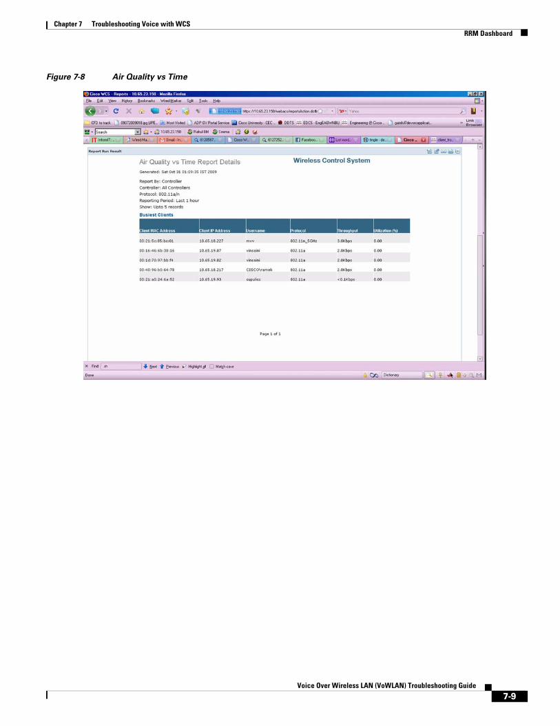
Chapter 7 Troubleshooting Voice with WCSRRM Dashboard
Figure 7-8 Air Quality vs Time
7-9Voice Over Wireless LAN (VoWLAN) Troubleshooting Guide

Chapter 7 Troubleshooting Voice with WCSRRM Dashboard
Figure 7-9 VoIP Calls Graph
7-10Voice Over Wireless LAN (VoWLAN) Troubleshooting Guide

Chapter 7 Troubleshooting Voice with WCSRRM Dashboard
Figure 7-10 VoIP Calls Table
7-11Voice Over Wireless LAN (VoWLAN) Troubleshooting Guide
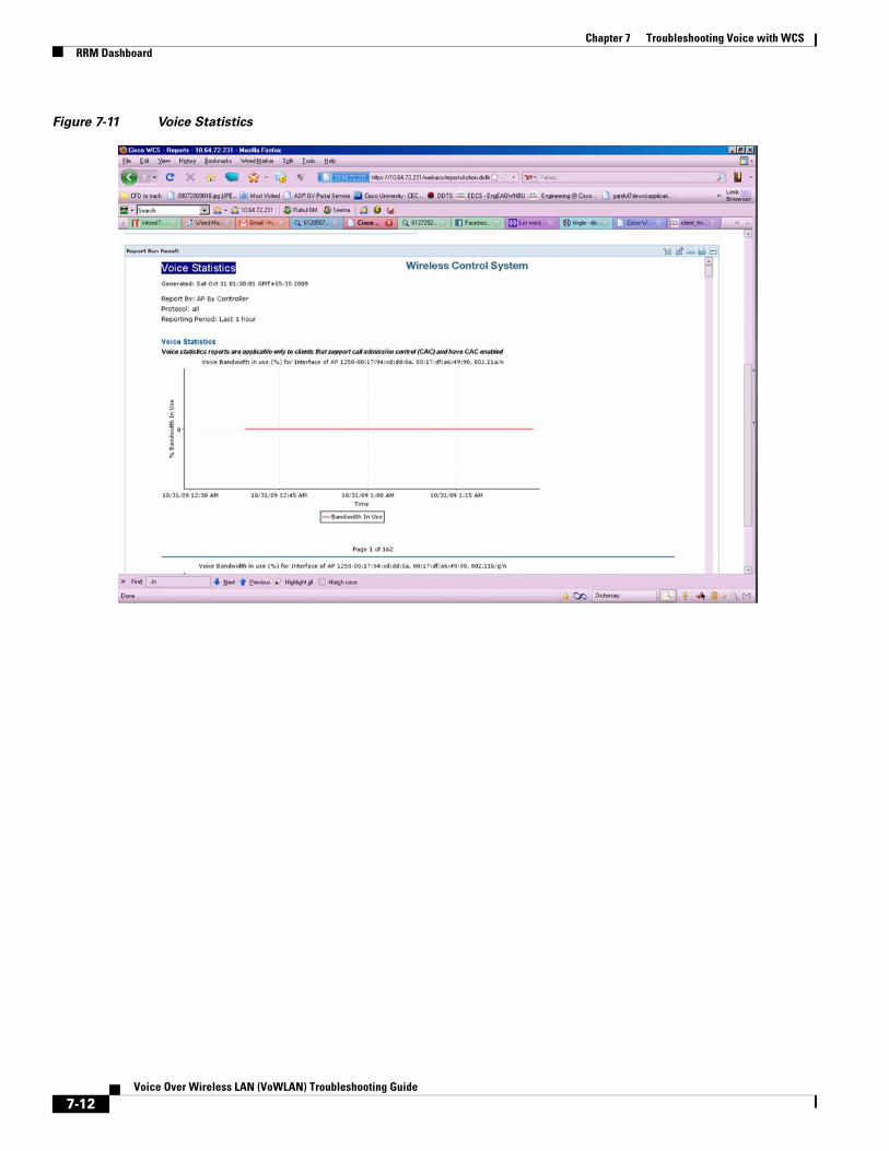
Chapter 7 Troubleshooting Voice with WCSRRM Dashboard
Figure 7-11 Voice Statistics
7-12Voice Over Wireless LAN (VoWLAN) Troubleshooting Guide

Chapter 7 Troubleshooting Voice with WCSRRM Dashboard
Figure 7-12 Voice Traffic Stream Metrics Table
7-13Voice Over Wireless LAN (VoWLAN) Troubleshooting Guide

Chapter 7 Troubleshooting Voice with WCSRRM Dashboard
Figure 7-13 Voice TSM Reports (1 of 3)
7-14Voice Over Wireless LAN (VoWLAN) Troubleshooting Guide

Chapter 7 Troubleshooting Voice with WCSRRM Dashboard
Figure 7-14 Voice TSM Reports (2 of 3)
7-15Voice Over Wireless LAN (VoWLAN) Troubleshooting Guide

Chapter 7 Troubleshooting Voice with WCSConfiguration Issues
Figure 7-15 Voice TSM Reports (3 of 3)
Configuration Issues • Customers need to spend enormous time to configure controllers as per the 792xG Series wireless
IP phone deployment guide
• Thick Deployment guide for 792xG Series wireless IP phone
• Difficult to check which configurations are altered, over a period of time
Run Voice Audit and Attach Report • The WCS does Online Auditing, in which device attributes are fetched from the network with Audit
is run.
• WCS will ship with canned rules called VoWLAN Audit Rules (VRs), each of which will represent an individual configuration check. VR can be individually turned on and off by the user. Also some of the VRs may require user data as an input. Example of a VR: “Enable QBSS.”
VoWLAN Audit • Validates the controller configuration against deployment guide recommendations or preconfigured
criteria.
• Default configuration check is based on the 792xG Deployment Guide.
• Allows customization of the configuration validation for other client types.
7-16Voice Over Wireless LAN (VoWLAN) Troubleshooting Guide

Chapter 7 Troubleshooting Voice with WCSVoWLAN Audit
• Some configuration validations are version dependent.
• Can be initiated on demand.
Figure 7-16 VoWLAN Audit Tool
7-17Voice Over Wireless LAN (VoWLAN) Troubleshooting Guide

Chapter 7 Troubleshooting Voice with WCSVoWLAN Audit Rules (VRs)
Figure 7-17 VoWLAN Audit Reporting
VoWLAN Audit Rules (VRs)
Check VoWLAN SSIDUser needs to define a set of VoWLAN SSIDs. Each controller will be checked for the existence of a subset of the user defined SSIDs.
Enable ARP CachingThis is a check box for user to enable/disable this option. This is a controller configuration.
Enable CAC • User needs to provide VoWLAN SSIDs.
• CAC needs to be enabled.
• User might provide Maximum Allowed Bandwidth and Reserve Roaming Bandwidth. The device config should have at least the user defined Bandwidth.
7-18Voice Over Wireless LAN (VoWLAN) Troubleshooting Guide

Chapter 7 Troubleshooting Voice with WCSVoWLAN Audit Rules (VRs)
• Expedited Bandwidth needs to be enabled.
• All the above will be checked for all the user defined SSIDs.
Enable TSM metric • User needs to provide VoWLAN SSIDs.
• TSM metrics need to be enabled for user defined SSIDs.
Enable DTPC • This is an interface-based configuration. User will be able to enable/disable per interface.
• AP configuration might have overridden this controller configuration via custom power assignment and this will result in AP level violation.
Enable DHCP server overrideUser needs to provide VoWLAN SSIDs. DHCP override option will be checked for all SSIDs that matched with the user defined SSID. Note that only one violation will be raised for multiple mismatches across SSIDs.
Check that Platinum QoS is used for VoWLANUser needs to provide the VoWLAN SSIDs. If a user-defined SSID is not present in the controller, then the rule will not be applied. The rule will be applied only when a matching SSID is found.
Check that Platinum QoS is not used for non-voice WLANUser needs to provide VoWLAN SSIDs. For all SSIDs excluding the user-defined ones, the QoS policy should be set to non-Platinum.
Check that QoS policies are left at defaultOne violation will be generated even if there are multiple mismatches across different QoS Profiles.
Check RF configuration • Beacon period: 100
• DTIM period: 1
• Fragmentation threshold: 2346
• Short preamble: Enable
• Pico cell mode: Disable
7-19Voice Over Wireless LAN (VoWLAN) Troubleshooting Guide

Chapter 7 Troubleshooting Voice with WCSVoWLAN Audit Rules (VRs)
• Each will generate an instance of violation for each RF configuration mismatch
Check that Data rate configuration is as below • Disabled: 1, 2, 5.5, 6, 9, 11
• Mandatory: 11
• Supported: 12,18,24,36,48,54
Note User will be able to change the values for each category. Note that only one violation will be raised for all mismatches.
Disable aggressive load balancingThe user must provide VoWLAN SSIDs. For the user-defined SSIDs, check if load balancing has been turned off.
Additional rules • WMM being set to “Allowed”/”Required”
• CCKM being enabled
• Pico Cell mode being disabled
• EAP Request timeout being set to 20 sec
• ACM being Enabled
7-20Voice Over Wireless LAN (VoWLAN) Troubleshooting Guide

Chapter 7 Troubleshooting Voice with WCSVoWLAN Client Troubleshooting
VoWLAN Client Troubleshooting Figure 7-18 Troubleshooting Client
Troubleshooting of client is divided into following categories (msgType)
• dot11(0) - dot11-related messages.
• dot1x(1) - dot1x, authentication-related messages.
• pem(2) - Policy Enforcement Module – client state machine related messages.
• dhcp(3) - DHCP-related messages.
• aaa(4) - AAA-related messages.
• voice(5) - Voice-related message. This is new msg type that will be added.
• misc(6) - Miscellaneous messages, such as Roaming, etc.
7-21Voice Over Wireless LAN (VoWLAN) Troubleshooting Guide
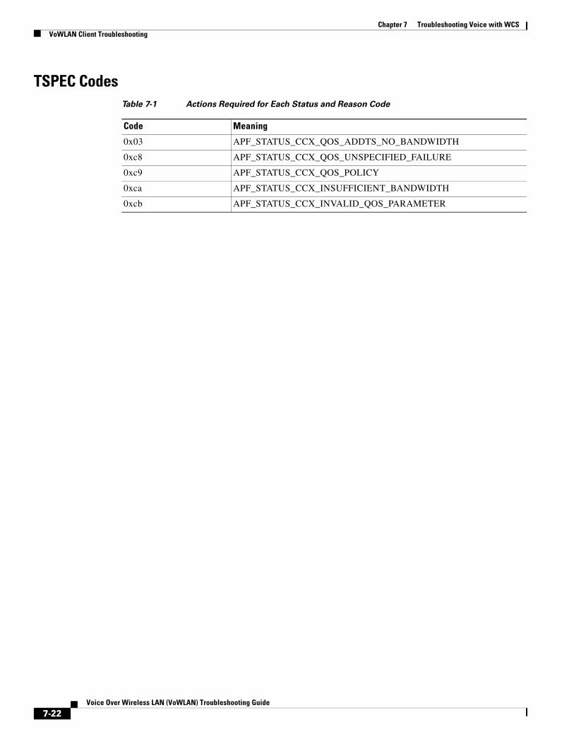
Chapter 7 Troubleshooting Voice with WCSVoWLAN Client Troubleshooting
TSPEC CodesTable 7-1 Actions Required for Each Status and Reason Code
Code Meaning
0x03 APF_STATUS_CCX_QOS_ADDTS_NO_BANDWIDTH
0xc8 APF_STATUS_CCX_QOS_UNSPECIFIED_FAILURE
0xc9 APF_STATUS_CCX_QOS_POLICY
0xca APF_STATUS_CCX_INSUFFICIENT_BANDWIDTH
0xcb APF_STATUS_CCX_INVALID_QOS_PARAMETER
7-22Voice Over Wireless LAN (VoWLAN) Troubleshooting Guide
Voice Ov
C H A P T E R 8
Site Survey and RF Design ValidationSite Survey IntroductionIn the realm of wireless networking, careful planning is essential to ensure that your wireless network performs in a manner that is consistent with Cisco’s design and deployment best practices. With that in mind, we cannot stress enough how important it is to perform a thorough site survey before and after the Cisco Unified Wireless deployment. A pre-site survey allows the systems engineer to assess requirements and design the network in manner that promotes and encourages scalability while also meeting expectations with regard to the applications the network will support.
Through our experiences, our TAC and Escalation Teams have discovered that many of our customers and even partners perform the site survey incorrectly or skip the site survey altogether. In almost 70% of Cisco wireless deployments, our Wireless Escalation Team and Advanced Services are called in to perform remediation for customers due to deviations from documented design and deployment best practices as they pertain to RF Design. In some cases, it is a matter of experience, and in others it is related to improper planning.
As we explore the possibilities, we have also determined that a majority of the environments were surveyed for data, but not for voice. When executives and IT managers think about purchasing solutions, they often consider buying equipment that will provide a good return on their investment. With that in mind, a wireless network that is going to be deployed throughout the enterprise should be designed and deployed for voice to ensure that it is scalable and that user mobility is enhanced.
Note While one organization might have a certain set of criteria for their wireless deployment, it is of vital importance to ensure that your company employs a Certified Cisco partner that has their Advanced WLAN specialization and also has a reputable background with regard to performing pre- and post-site surveys.
For the purposes of this troubleshooting guide, we will assume that the wireless network has already been deployed. Based on this, we will focus on what tools can be used to isolate RF-related problems, such as excessive retransmissions, RF multipath, and co-channel interference, and we will discuss topics and tools related to performing a post audit along with RF analysis of the existing wireless network. Since the focus of this document will be on troubleshooting, we will discuss the basics of performing a post-site survey as it pertains to the proper deployment of a VoWLAN.
8-1er Wireless LAN (VoWLAN) Troubleshooting Guide

Chapter 8 Site Survey and RF Design ValidationPerforming a Post Site Survey Assessment
Performing a Post Site Survey AssessmentThe need for a wireless site survey is different in every situation. Performing a post assessment of the environment is very similar to a pre-site survey. There are particular guidelines and criteria that need to be met. Once a systems engineer has determined that VoWLAN users are being subjected to audio problems due to inadequate signal, interference, or other RF-related problems, performing a post survey of the environment becomes crucial from a troubleshooting perspective.
Environmental CharacteristicsWhen preparing to perform a post analysis of the environment, be certain to consider the environmental characteristics of the building or site where the wireless network was deployed. A large building with several floors may require only a minimal amount of time, especially if each floor has a similar physical blue print, however, it is important to evaluate every floor individually. An environment such as an ocean liner may vary completely from deck to deck and will prevent you from using a cookie cutter approach. The following are elements that you should consider when performing a post assessment of the environment.
1. Review requirements: For VoWLAN deployments, it is crucial to understand what the transmit power of the client device is to ensure that access points and VoWLAN handsets transmit at the same power. This will mitigate problems such as one-way audio.
2. Wireless tools: When performing the post assessment, it is also recommended that you use wireless tools such as Cisco Spectrum Expert, Wireshark, Omnipeek, and AirMagnet to the isolate root cause of RF-related problems.
3. Obtain building and floor blue prints: WCS is a great place to start your evaluation. Remember, while WCS will show you the physical layout of a building, WCS should not be used as a primary tool for performing a post wireless audit.
4. Inspect the environment: As you are troubleshooting a problem-related RF propagation or a lack thereof, it is important to perform a physical walk-through of the environment and take into account where the access points have been placed, what types of antennas are in use, the height of the access points, and the direction of each antenna as it relates to the respective coverage area.
5. Evaluate the LAN: When performing a post audit, evaluation of the wired infrastructure is important for several reasons. First and foremost, you want to ensure that the physical LAN can sustain the appropriate level of throughput without QoS. This will ensure that voice traffic can later be assigned to queues or marked with a level of QoS that facilitates greater priority as voice traffic traverses the infrastructure. Once you have validated the physical topology, you can then trust packets according to DSCP or CoS and ensure that voice packets traverse the wired and wireless LAN with the appropriate level of QoS.
6. Identify sources of RF interference: This is probably the most important aspect of a post audit when deploying 802.11a/b/g/n solutions on the 2.4 and 5 GHz bands. Often there are several different types of interferers. The most common of these are from commercial grade microwave ovens, blue tooth devices, and cordless phones that operate on the 2.4 GHz frequency band. The most common tool used by wireless engineers at Cisco is Cisco Spectrum Expert. Spectrum Expert is an analysis tool that can used to locate and isolate sources of interference and identify above average channel utilization after the initial deployment. Refer to the section “RF Design Validation” for channel utilization recommendations.
7. Analyze and define the cell edge: This requires the use of AirMagnet Survey, although there are simple tools like Omnipeek or Wireshark that can be used to measure wireless traffic as a client roams from one AP to another. According to design best practices that revolve around the Cell Edge
8-2Voice Over Wireless LAN (VoWLAN) Troubleshooting Guide

Chapter 8 Site Survey and RF Design ValidationVoWLAN RF Design Validation
Design, a wireless handset should roam before the RSSI reaches -67 dBm. You can analyze signal strength and determine the approximate cell edge by measuring the signal strength in a beacon frame as you move from the center of one cell towards the edge of that cell.
8. Validate antenna usage and AP placement: As it pertains to RF design and deployment best practices, we suggest performing advanced wireless in an effort to understand how RF propagates with the existing environment.
9. Post-Site Survey Report: The wireless post audit report should contain detailed facts about the existing deployment and outline deviations in design and deployment best practices. The purpose of this report should be to provide systems engineers with enough information to successfully remediate the existing deployment to ensure proper functionality, high availability, and seamless user mobility with minimal delay and jitter.
VoWLAN RF Design Validation
Troubleshooting Radio Frequency DesignThe most important aspect of any VoWLAN is user mobility. Systems Engineers need to ensure that the existing WLAN will facilitate user needs, while also ensuring that users have seamless connectivity while moving throughout their enterprise. Voice has stringent requirements with regard to Radio Frequency Design, and understanding RF propagation and VoWLAN design and deployment best practices is essential for successful voice over wireless LAN deployments.
When troubleshooting a VoWLAN specifically, it is important to understand how packet loss and jitter will affect voice quality. Specifically, Cisco references a principle referred to as Cell Edge Design when deploying access points and antennas. Deploying the VoWLAN according to this design principle will ensure that your VoWLAN is highly available so that users can move seamlessly throughout the network.
When troubleshooting issues that pertain to a lack of RF coverage, interference, or issues that might be related to user mobility, it is important to understand the following design fundamentals as they relate to the Cell Edges Design principle, channel utilization, noise, retransmissions, and overall packet loss and delay.
RF Design Validation1. The optimal VoWLAN Cell Edge recommendation is -67 dBm.
2. An optimal VoWLAN deployment will require at least a 20 percent cell overlap for 2.4 GHz and 15-20 percent for 5 GHz for access points that reside on different channels.
3. Over all Channel Utilization should be less than 50 percent.
4. The Noise floor should not exceed -92 dBm, which facilitates a Signal to Noise Ratio of 25 dB.
5. Retransmissions should be kept under 20 percent.
6. Packet Loss should remain under 1 percent and jitter should be kept to less than 100 ms.
Cisco Enterprise Mobility Design Guide 4.1http://www.cisco.com/en/US/docs/solutions/Enterprise/Mobility/emob41dg/emob41dg-wrapper.html
8-3Voice Over Wireless LAN (VoWLAN) Troubleshooting Guide
Chapter 8 Site Survey and RF Design ValidationSite Survey Tools
Voice over Wireless LAN 4.1 Design Guidehttp://www.cisco.com/en/US/docs/solutions/Enterprise/Mobility/vowlan/41dg/vowlan41dg-book.html
Note If you are troubleshooting and you determine that the VoWLAN does not adhere to the outlined requirements above, we strongly encourage you to perform a post site survey and assess the existing RF Design. The following section should provide you with sufficient information to analyze the RF environment and remediate the wireless deployment until the RF design meets the appropriate criteria.
Site Survey ToolsIn most cases, we hope that a pre- and post-site survey have already been performed before deploying the Cisco Unified Wireless Network for Voice. In a situation where it has not been performed, a post audit of the environment is essential to understand the existing RF design and to remediate the network until it is accordance with Cisco’s Design and Deployment best practices for VoWLAN deployments.
AirMagnet Survey and VoFi AnalyzerAirMagnet Survey and AirMagnet VoFi Analyzer are primary solutions used by the Cisco Escalation and Advanced Services Teams for managing, remediating, and optimizing a Cisco Unified VoWLAN. AirMagnet Surveyor itself provides information related to RF propagation within the physical environment. AirMagnet Survey also has preconfigured profiles for the Cisco 792xG Series wireless IP phone that allow Survey to predict RF propagation and to validate and plot the phone call performance, call capacity, RF coverage and roaming behavior at every location on a floor map. This eventually leads to root cause analysis with regard to poor call performance.
In Figure 8-1, we show a post assessment where a systems engineer walked an area where a VoWLAN issue was being experienced. As you can see in the following figure, Figure 8-2, the screen shot displays the information for those access points and the signal strength for each area that was assessed using the survey utility.
8-4Voice Over Wireless LAN (VoWLAN) Troubleshooting Guide

Chapter 8 Site Survey and RF Design ValidationSite Survey Tools
Figure 8-1 Walk-Through
Figure 8-2 Signal Strength for Given Area
8-5Voice Over Wireless LAN (VoWLAN) Troubleshooting Guide

Chapter 8 Site Survey and RF Design ValidationSite Survey Tools
Note While WCS can be used for planning, location tracking, and RF visualization, the heat maps in WCS are predictive based on the antenna type, antenna direction and power levels configured on the Wireless LAN Controller. WCS should not be used as a pre- or post-site survey tool by any means.
With regard to the VoWLAN and the RTP stream between the AP and 792xG Series wireless IP phone, a poor or unreliable RTP stream can have any number of potential problems. It may be an issue with the 792xG Series firmware specifically, the RF environment, a misconfiguration, a QoS marking over the air, or even problems over an IP-PBX or H.323 gateway. Due to the level of complexity, VoWLAN troubleshooting can become particularly challenging and time-consuming to diagnose.
AirMagnet also has a Wi-Fi Analyzer and VoFi Analyzer which have the ability to display your network in terms of calls and call quality. VoFi Analyzer works in the same manner as a protocol analyzer and has the ability to score every RTP stream in terms of WiR-Value and a WiMOS score based on packet metrics, such as loss rate and jitter.
As you can see in Figure 8-3, each call is color-coded according to call quality. The VoFi Analyzer displays streams that experience problems.
Figure 8-3 VoFi Pro Analyzer
The AirWise analysis engine in VoFi Analyzer also has the ability to detect common problems within the VoWLAN such as choppy audio, one-way audio, and no audio, and provides easy-to-understand data based on configurable alarms.
8-6Voice Over Wireless LAN (VoWLAN) Troubleshooting Guide

Chapter 8 Site Survey and RF Design ValidationSite Survey Tools
In addition to troubleshooting call streams from an RF perspective, the VoFi Pro Analyzer can be used to receive syslog data directly from the Cisco 792xG Series wireless IP phone. This is ideal when troubleshooting issues related to excessive roaming due to RSSI differential seen by the handset or RF related problems such as multi-path.
Detailed information about the AirMagnet suite of products can be found at the following location:
http://www.airmagnet.com/
Cisco Spectrum ExpertCisco Spectrum Expert Wi-Fi integrates with the Cisco Unified Wireless Network to deliver real-time spectrum intelligence data. Cisco Spectrum Expert has the ability to detect, classify, and locate sources of RF interference in the unlicensed 2.4-GHz and 5-GHz bands.
WCS and Spectrum IntelligenceWhile Cisco Spectrum Expert can be used as a separate tool, the Cisco Wireless Control System (WCS) also works in conjunction with Cisco Spectrum Expert to provide visibility into interference sources that may cause wireless performance degradation. With Cisco Spectrum Expert Wi-Fi, the source of the interference can be determined, allowing businesses to remove, move, shield, adjust, or replace the source of interference.
The WCS and Cisco Spectrum Expert Wi-Fi is part of the Cisco’s Spectrum Intelligence solution and integrates with the Cisco Unified Wireless Network to monitor the wireless network.
To implement and utilize this for troubleshooting, systems engineers need to adhere to the following criteria.
• Cisco Spectrum Expert Wi-Fi
• Cisco Wireless Control System (Software Release 4.2 or later)
• Cisco WCS Spectrum Intelligence license
8-7Voice Over Wireless LAN (VoWLAN) Troubleshooting Guide

Chapter 8 Site Survey and RF Design ValidationSite Survey Tools
WCS and Cisco Spectrum Intelligence
Figure 8-4 WCS and Cisco Spectrum Intelligence
8-8Voice Over Wireless LAN (VoWLAN) Troubleshooting Guide

Chapter 8 Site Survey and RF Design ValidationSite Survey Tools
Figure 8-5 Wireless Control System
Wireless Sniffer
Wireshark or Omnipeek
Once you have isolated and remediated the RF problems, refer to the sections on General Troubleshooting and using Omnipeek for instructions on how to take wireless sniffer traces to analyze a VoWLAN.
Note With regard to following VoWLAN design and deployment best practices, Cisco does not support a same-channel design as used in some Distributed Antenna System (DAS) deployments. A VoWLAN design must include a minimum of the three non-overlapping channels that are consistent with the 802.11 specifications for 2.4 GHz and 5 GHz.
8-9Voice Over Wireless LAN (VoWLAN) Troubleshooting Guide

Chapter 8 Site Survey and RF Design ValidationSite Survey Tools
Note The Coverage Hole Algorithm is a mechanism built into Radio Resource Management (RRM) that will increase the transmit power of an AP to ensure the appropriate amount of coverage once a certain number of clients roam into the coverage hole (three or more clients by default). While this is a feature, it is important to implement bandwidth throttling on the controller for the 2.4 GHz band. Throttling the transmit power of the AP will ensure that asymmetric transmit does not occur, leading to one-way audio. DTPC is another mechanism that can potentially remedy this issue as well.
8-10Voice Over Wireless LAN (VoWLAN) Troubleshooting Guide