vwhpv - altrad-pomorze szczecin · introduction in november 2008, altrad-mostostal received a...
TRANSCRIPT

CATALOGUE 200906/2009
Formwork systems

INTRODUCTION .................................. .......................................................................................................................
I. WALL FORMWORKS – INTRODUCTION ....................................................................................................................
1. MIDI BOX FORMWORKS .................................................................................................................................................
2. POLE FORMWORKS (universal for poles and walls) .................................................................................................
3. LIFT SHAFT FORMWORK ........................................................................................................................................
4. SUPPORTING TRESTLES (for one-sided formwork) .................................................................................................
II. CEILING FORMWORKS – INTRODUCTION .................................................................................................
1. LOAD CAPACITY OF THE CEILING FORMWORK'S SUPPORTS TABLE ................................................................
2. CEILING FORMWORKS – CHARACTERISTIC ...........................................................................................................
3. BASE ELEMENTS OF STANDARD CEILING AND ALUSTROP CEILING .................................................................
4. STANDARD CEILING SYSTEM ..................................................................................................................................
5. ALUSTROP ...................................................................................................................................................................
6. S10 SUPPORTING TOWER III. ACCESSORIES ........................................................................................................
III. ACCESORIES ........................................................................................................................................................
IV. ROTAX SUPPORTING TOWER ........................................................................................................................
V. STAIRCASES (ROTAX, FACADE) ....................................................................................................................
Contents
CONTENTS 1
3
6
15
23
27
28
30
30
31
37
38
40
42
44
46
47

Building constructed with ALTRAD-Mostostal technology

INTRODUCTION
The strength of ALTRAD-Mostostal lies in over 10 years of experience on Polish and European market (e.g.:
Germany, France, Norway, Italy, Russia, Ukraine, Croatia, Denmark). The company is based on reliable
foundations of the international, French based ALTRAD Group.
Over the years we have been improving our production and technological cycle in order to meet your
expectations. Our products are renowned for the most reliant anti-corrosion protection – hot-dip zinc coating.
With proper hardware maintenance, it allows you to use the formwork set for many years.
Our product's design and manufacturing process is in accordance with ISO 9001:2000 Quality Management
System standards. Representative for Quality Assessment, called by the Management Board, is responsible for
keeping proper procedures and regulations of ISO 9001:2000 standard throughout design and production
phases as well as during the final delivery of the product.
INTRODUCTION 3
Since many years the company has been a member of Polish Chamber of Commerce – Scaffoldings – a
sector institution and an economical self-government organization that represents (especially towards
government authorities) economical interests of associated business entities that produce, sell, and assemble
scaffoldings .
Current catalogue features a broad range of formworks offered by our company.
ALUSTROP
SUPPORTING TOWER
LIFT SHAFT
Our goal is to surprise you with new products and innovations, such as:
light and durable ALUSTROP, which acts in the same way as standard ceiling, but at the same time is more
economical in use;
the design of the SUPPORTING TOWER, which is used to build supporting structures for working platforms,
gang-boards and load-bearing constructions;
ECO PLATFORMS easy to assemble, light structure that maintains resistant properties of a traditional, steel
plank;
LIFT SHAFT with formwork removing element which, once set-up, can be used on all subsequent levels of the
building.
-
-
-
-
INTRODUCTION
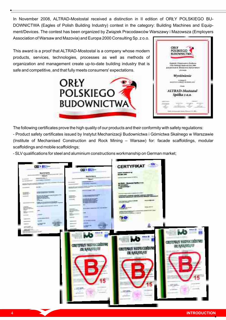
In November 2008, ALTRAD-Mostostal received a distinction in II edition of ORŁY POLSKIEGO BU-
DOWNICTWA (Eagles of Polish Building Industry) contest in the category: Building Machines and Equip-
ment/Devices. The contest has been organized by Związek Pracodawców Warszawy i Mazowsza (Employers
Association of Warsaw and Mazovia) and Europa 2000 Consulting Sp. z o.o.
This award is a proof that ALTRAD-Mostostal is a company whose modern
products, services, technologies, processes as well as methods of
organization and management create up-to-date building industry that is
safe and competitive, and that fully meets consumers' expectations.
The following certificates prove the high quality of our products and their conformity with safety regulations:
- Product safety certificates issued by Instytut Mechanizacji Budownictwa i Górnictwa Skalnego w Warszawie
(Institute of Mechanised Construction and Rock Mining – Warsaw) for: facade scaffoldings, modular
scaffoldings and mobile scaffoldings;
- SLV qualifications for steel and aluminium constructions workmanship on German market;
4

5
ALTRAD-Mostostal Spółka z o.o.;
tel.: 0 801 ALTRAD (0 801 2 5 8 7 2 3) , tel.: +48 25 644 82 93, fax: +48 25 644 62 62
ul. Starzyńskiego 1, 08-110 Siedlce
ADEPT
tel: 063 245 85 17, Konin
ATTYKA Sp. z o.o.
tel: 055 232 62 27, Elbląg
BPM Sp. z o.o.
tel: 085 745 47 68, Białystok
CAPITAL Sp. z o.o.
tel: 058 307 25 77, Gdańsk
CHRABĄSZCZ Rusztowania
tel: 056 654 85 62, Toruń
FASADEXTAR
tel: 014 627 35 68, Tarnów
We are looking forward to working with you!
INTRODUCTION
Detailed information on: http://altrad-mostostal.pl/en
SZCZECIN
ŁÓDŹ
WARSZAWA
SIEDLCE
BIAŁYSTOK
KONIN
BYDGOSZCZ
ELBLĄG
TORUŃ
TARNÓWRZESZÓW
MOTYCZ(k/Lublina)KOŃSKIE
DZIERŻONIÓW(k/Wrocławia)
GDAŃSK
Full ALTRAD-Mostostal offer includes: design, production and sale of scaffolding structures, formworks
and other building accessories. Our offer includes the following formworks: wall MIDI BOX and MIDI BOX
Plus; ceiling: ALUstrop (light, aluminium ceiling), standard ceiling formwork system, and the following
scaffoldings: frame, ROTAX modular, MP mobile; as well as the following structures: supporting towers, external
staircases; formworks for pole forming; lift shaft formwork, etc.
We act: comprehensively, efficiently and fast. Starting from the design process, up to the delivery of a full
formwork or scaffolding set to the building site.
Scaffoldings and formworks offered by ALTRAD-Mostostal is a high-end equipment at competitive prices.
The following Technical/Trade Advisors will answer your inquiries:
or ALTRAD-Mostostal Trade Representatives:
ORENO
tel: 052 379 80 55, Bydgoszcz
OSTAP Sp. z o.o.
tel: 022 610 94 49, Warszawa
PRO-MEN Sp. z o.o.
tel: 081 503 00 52, Motycz (near Lublin)
SLABAK
tel: 042 689 83 69, Łódź
ALTRAD-Końskie Spółka z o.o.
tel: 041 375 12 48, Końskie
ALTRAD-Mostostal-Montaż Spółka z o.o.
tel: 025 631 03 50, Siedlce
ALTRAD-Pomorze Spółka z o.o.
tel: 091 469 37 26, Szczecin
ALTRAD-Prymat Spółka z o.o.
tel: 074 832 30 57, Dzierżoniów (near Wrocław)
INTERPETRO Sp. z o.o.
tel: 017 862 18 17, Rzeszów

I. WALL FORMWORKS – INTRODUCTION
ALTRAD-Mostostal offers a range of wall formwork systems, including:
- MIDI BOX system [60 kN];
- MIDI BOX Plus system [80 kN];
- pole forming system;
- lift shaft formwork;
- supporting trestles (formwork for one-sided formwork).
Full range of wall formwork system elements, that are compatible, co-functioning, self-complementary and
exchangeable, allows designing perfect formwork for any wall. When full MIDI BOX set is in use, you can stay
assured that any building project will be possible to undertake in self-sufficient, economical, proficient and quick
manner.
Wall formwork is:
- spatial system, multiple assembly,
- system for average (MIDI BOX) and heavy (MIDI BOX Plus)
loads — withstands concrete's pressure up to 80 kN/m2;
- high-end products (produced with high quality materials —
hot-dip zinc coated steel; plywood planking made of multi-
layered plywood, covered double-sided with fenofil foil);
- concrete surface smoothness that does not require
plastering after formwork removal, but only needs thin
plaster or filling.
MIDI BOX and MIDI BOX Plus systems used for realization of:
- combined footing,
- mid-sized and heavy walls,
- rectangular section poles,
MIDI BOX PLUS shuttering boards – building site
MIDI BOX boards – building site
Pole forming
MIDI BOX shuttering boards
I. WALL FORMWORKS6

MIDI BOX wall formwork:
Mid-sized formwork that can be assembled at the building site without crane.
MIDI BOX formwork's permissible concrete's pressure:
- 60 kN/m2 – assembly without superstructures;
- 55 kN/m2 – assembly with superstructures;
MIDI BOX formwork is available with a full range of shuttering boards measuring from 25 cm up to 90 cm width,
and the height of 150 cm, 270 cm and 300 cm.
MIDI BOX Plus board basic system element
MIDI BOX shuttering boards – exhibition
MIDI BOX formwork — building site in Sarajevo
MIDI BOX Plus wall formwork:
Heavy formwork — crane assembly, permissible concrete's pressure - 80 kN/m2.
Basic system elements are large size shuttering boards measuring from 90 cm up to 240 cm width, and the
height of 270 cm and 300 cm.
Building site — MIDI BOX
MIDI BOX corner setting Exemplary MIDI BOX system combinations
All junction and additional elements which are in MIDI BOX system can be used with MIDI BOX Plus.
The use of both systems together allows efficient and optimal deployment of any chosen formwork. In order to
move quickly entire MIDI BOX and MIDI BOX Plus sets, hoisting hooks can be used without the need of
disassembling.
I. WALL FORMWORKS 7
- binders,
- lift shafts,
- and many other building elements.

Multipurpose boarding lock BM260 and BM710 reliably
connects shuttering boards, clamps corners and poles with
simultaneous function of surface straightening.
Additional stiffening in case of larger walls (both vertical and
horizontal) is achieved with the use of boarding transoms and
stiffening beams which can replace the BM710 lock.
Walls as high as 270 cm or 300 cm are to be connected with three
BM260 locks for one board contact place. Shuttering boards in
level raisers are to be connected with BM710 locks. These locks
have longer straightening foot (710 mm), which makes the
formwork straightening surface larger.
Multipurpose boarding lock
Using circular slats it is possible to board many-sided constructions with a radius over 2.5 m. Having the
possibility to choose three sizes of circular slats (15, 20 and 25 cm) and all the MIDI BOX and MIDI BOX Plus
boards, it is also possible to precisely set up the formwork without the use of filling inserts. Circular slats are
connected to boards with locks and centering bowstrings alternately.
Circular slats – design
When there is a necessity to add a section to equal the length of walls, filling inserts can be used. It is a perfect
solution when there is no possibility to acquire desired length of formwork with shuttering boards alone. In such
case, wooden or steel inserts should be placed between boards.
ALTRAD-Mostostal offer includes typical 5cm wide, wooden and steel, inserts, as well as complementary filling
inserts allowing compensating the length of the formwork within 7÷30 cm range. In case of wooden and steel
inserts, board connection should be made with BM260 and BM710 locks, which allow the connection of 15 cm
long inserts, and boarding transoms that stiffen the formwork and clasp the inserts.
Circular slats – scheme
Shuttering board Circular slat Bowstring's beam
I. WALL FORMWORKS8

MIDI BOX and MIDI BOX Plus systems are compatible. Diversity of the
boards allows optimal set-up of any formwork. Both systems assure
concrete surface smoothness, that does not require plastering after
formwork removal . Thin plaster and filling may be applied.
Plywood disfigurement, due to concrete's pressure, hinders
dense frame's ribbings with integrated holders that allows
handy grip and elements transport. System's elements
connect in a comfortable, fast and safe way, thanks to a
large number of openings present throughout the steel
structure.
Shuttering boards plumbing is performed with the use of:
- tilt support – used for shuttering boards plumbing up to
the height of 3 m,
- raking shore – used for shuttering boards plumbing above
the height of 3 m,
MIDI BOX and MIDI BOX Plus
formwork sets, through the
d e s i g n , p r e c i s i o n a n d
protective measures, provide
personnel safety during:
- assembly,
- concrete filling,
- disassembly.
MIDI BOX and MIDI BOX Plus systems allow the selection of boards with modules
placed every 5 cm (vertically and horizontally). Shuttering boards can be
interconnected in any desired configuration. Please remember that a standard
board set-up is vertical. Horizontal set-up is to be treated as a supplement.
I. WALL FORMWORKS 9
Wall formwork element for exterior wall formwork is a climbing
shuttering's bracket. Brackets are used up to the height of H=100 m.
Maximum formwork height: 4.2 m — without additional anchoring of
shuttering board. Maximum bracket spacing: 1.35 m. Bracket needs to be
anchored with SKK cones, and waved or looped B15 anchors. Cone is a
recoverable element.
Climbing shuttering's bracket
Climbing shuttering – scheme
Tilt support

10
Lift shaft formwork is used for fast assembly and disassembly of
internal formwork in lift shafts, without the need of separate
disassembly of each element. It is possible with a formwork
removing element that reduces the size of internal formwork
segments by 5 cm. This allows free removal of the set from the lift
shaft.
LIFT SHAFT FORMWORK
Lift shaft formwork
ASSEMBLY STEPS:
Lift shaft formwork assembly starts with a set-up of internal segment.
One formwork wall receives one lift shaft element. The width of boards and wooden inserts should be selected
bearing in mind that the formwork removing element should be placed in symmetry axis of the set.
the steel sheet of formwork removing element fits tight to the plywood due to stiffening beams, which additionally
straighten the formwork.
For comfort purposes it is advised to use 50 cm wide boards. It allows direct attachment to the formwork
removing element.
Maximum diameter of the nut that connects formwork removing element with the basic board, is 10 cm.
Formwork removing element is a system element of MIDI BOX
and MIDI BOX Plus wall formworks. It is made of steel profiles and
steel sheet. Formwork removing element is present with all
standard shuttering boards.
Lift shaft formwork – scheme
Formwork removing
element
I. WALL FORMWORKS
I. WALL FORMWORKS 11
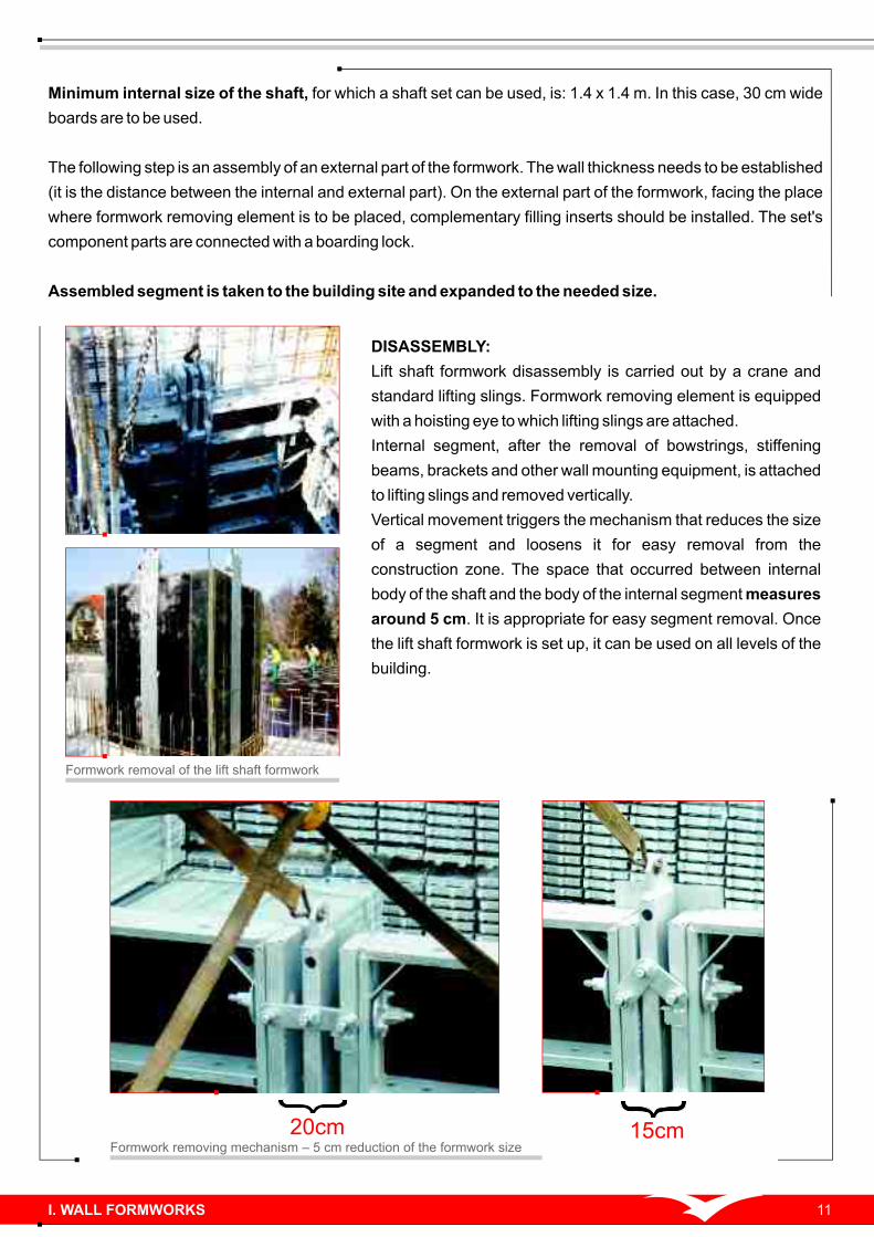
DISASSEMBLY:
Lift shaft formwork disassembly is carried out by a crane and
standard lifting slings. Formwork removing element is equipped
with a hoisting eye to which lifting slings are attached.
Internal segment, after the removal of bowstrings, stiffening
beams, brackets and other wall mounting equipment, is attached
to lifting slings and removed vertically.
Vertical movement triggers the mechanism that reduces the size
of a segment and loosens it for easy removal from the
construction zone. The space that occurred between internal
body of the shaft and the body of the internal segment measures
around 5 cm. It is appropriate for easy segment removal. Once
the lift shaft formwork is set up, it can be used on all levels of the
building.
Formwork removal of the lift shaft formwork
Minimum internal size of the shaft, for which a shaft set can be used, is: 1.4 x 1.4 m. In this case, 30 cm wide
boards are to be used.
The following step is an assembly of an external part of the formwork. The wall thickness needs to be established
(it is the distance between the internal and external part). On the external part of the formwork, facing the place
where formwork removing element is to be placed, complementary filling inserts should be installed. The set's
component parts are connected with a boarding lock.
Assembled segment is taken to the building site and expanded to the needed size.
15cm20cmFormwork removing mechanism – 5 cm reduction of the formwork size
I. WALL FORMWORKS12
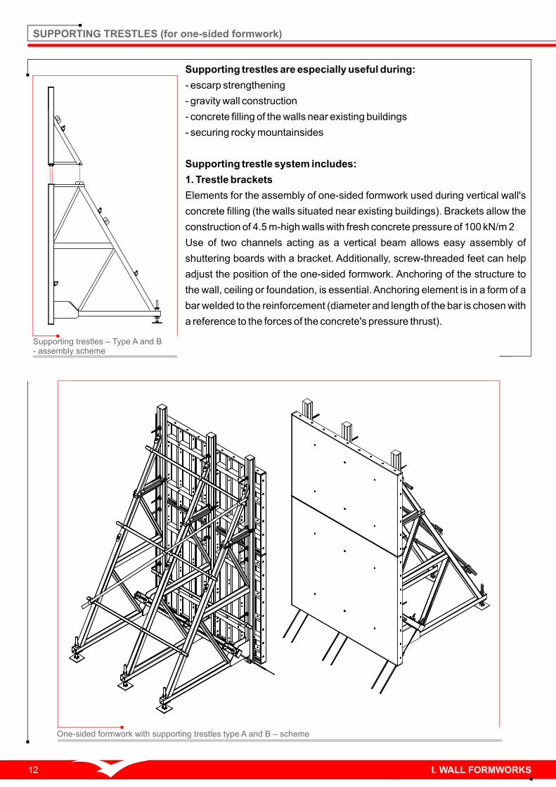
Supporting trestles are especially useful during:
- escarp strengthening
- gravity wall construction
- concrete filling of the walls near existing buildings
- securing rocky mountainsides
Supporting trestle system includes:
1. Trestle brackets
Elements for the assembly of one-sided formwork used during vertical wall's
concrete filling (the walls situated near existing buildings). Brackets allow the
construction of 4.5 m-high walls with fresh concrete pressure of 100 kN/m 2
Use of two channels acting as a vertical beam allows easy assembly of
shuttering boards with a bracket. Additionally, screw-threaded feet can help
adjust the position of the one-sided formwork. Anchoring of the structure to
the wall, ceiling or foundation, is essential. Anchoring element is in a form of a
bar welded to the reinforcement (diameter and length of the bar is chosen with
a reference to the forces of the concrete's pressure thrust).
SUPPORTING TRESTLES (for one-sided formwork)
One-sided formwork with supporting trestles type A and B – scheme
Supporting trestles – Type A and B - assembly scheme

I. WALL FORMWORKS 13
2. Angle bracket
Serves for establishing the location of the shuttering board against the trestle bracket. It also prevents the board
from dislocating under its own weight.
3. Wide angle bracket
Serves for establishing the location of the shuttering board against the trestle bracket, with the use of the
stiffening beam. It also prevents the board from dislocating under its own weight.
4. Clamping beam – 1.2 m and 2.6 m
Serves for clamping the trestle brackets. Serves for relocating the horizontal concrete's pressure force to
the anchors.
5. Trestle bracket – Type A and B
These brackets have different heights. Trestle bracket type B is used for concrete filling of the 2.9 m-high walls.
Trestle bracket type A is used for concrete filling of the walls measuring above 2.9 m. In such case, it is placed
onto the trestle bracket type B. Trestle bracket type A cannot be used separately. It is always used together with a
trestle bracket type B. Trestle bracket type B can be used separately.
Other wall formwork elements
Other wall formwork elements that co-operate with trestle brackets, are following:
- rotary coupling
- angle bracket
- mid-sized angle bracket
- tighteners
- flanged nut
- stiffening beam
- bowstring
- universal pipe
Please remember that the structure of the supporting trestle requires proper anchoring to the base.
Supporting trestles – set assembly

I. WALL FORMWORKS14
POLE FORMWORKS (universal for poles and walls)
Pole forming – scheme
Board connection – scheme
Pole forming – MIDI BOX boards and BM260 locks
I. WALL FORMWORKS
MIDI BOX – building site – pole forming
POLE FORMING.
1. Pole forming with SP boards.
SP shuttering board is used during boarding of square and rectangular
poles in the module placed every 5 cm, with a height of 5.4 cm and section
ranging from 55x55 cm for SP70 boards and 75x75 cm for SP90 boards.
Permissible concrete's pressure during pole forming with SP boards 2equals 80 kN/m .
2. Pole forming with basic shuttering boards.
Poles that are higher than the board can be formed by placing the boards
on top of each other and connecting them with a BM710 lock.
2
1
3
SP nut
SP bolt
Ø110 round nut

Weight (kg)
83.8
93.7
168
260
315
53.3
56.3
63.0
66.0
68.6
71.8
73.9
78.3
92.7
103
168
186
288
348
Index
a0427075
a0427090
a0427120
a0427180
a0427240
a0430025
a0430030
a0430040
a0430045
a0430050
a0430055
a0430060
a0430065
a0430075
a0430090
a0430100
a0430120
a0430180
a0430240
Dimensions (cm)
270x75
270x90
270x120
270x180
270x240
300x25
300x30
300x40
300x45
300x50
300x55
300x60
300x65
300x75
300x90
300x100
300x120
300x180
300x240
Index
a0215025
a0215030
a0215045
a0215050
a0215055
a0215060
a0215065
a0215075
a0215090
a0227025
a0227030
a0227045
a0227050
a0227055
a0227060
a0227065
a0227075
a0227090
Weight (kg)
20.6
22.1
27.0
28.4
29.9
31.4
33.5
36.7
41.5
35.4
38.0
46.3
48.5
51.2
53.5
57.0
62.5
70.8
Dimensions (cm)
150x25
150x30
150x45
150x50
150x55
150x60
150x65
150x75
150x90
270x25
270x30
270x45
270x50
270x55
270x60
270x65
270x75
270x90
1. MIDI BOX shuttering board [60 kN]
2. MIDI BOX Plus shuttering board [80 kN]
MIDI BOX Plus is a heavy,
high load formwork system.
MIDI BOX and MIDI BOX
Plus are compatible and
fully co-functioning. All
junction and additional
elements in MIDI BOX
system can be used in MIDI
BOX Plus.
1. MIDI BOX FORMWORK
MIDI BOX – mid-size
shuttering board system.
Frames and ribbed
shuttering boards are
made of high endurance
steel that was hot-dip
zinc coated.
I. WALL FORMWORKS
300
15
00
12
1
30
03
00
30
03
00
15
0
18001020
27
00
300
150
121
15

Weight (kg)Index
a0516150
a0516270
a0516300
Dimensions(cm)
150x30
270x30
300x30
40.3
70.3
89.3
4. Hinged corner
3. Internal corner
o Serves for boarding of internal 90 angle.
Serves for boarding of internal and external angles
measuring 60° up to 270°.
5. External corner
Used for fast connection of shuttering boards in
external, rectangular angles.
Weight (kg)Index
a0517150
a0517270
a0517300
a0518150
a0518270
a0518300
Dimensions (cm)
150x15
270x15
300x15
150x30
270x30
300x30
27.5
48.2
53.7
40.9
71.3
93.2
Weight (kg)Index
a0515150
a0515270
a0515300
Dimensions (cm)
150x12
270x12
300x12
14.2
25.3
26.8
30
0
15
00
30
0
300
30
0
15
00
12
1
121
15
0
286
15
00
1500
150
300
121 121
I. WALL FORMWORKS16

6. Boarding lock
BM multipurpose boarding lock. Also straightens and
stiffens the formwork.
Nazwa
40
26
0
12
0
260
7. Circular slats
Serves for boarding of arched structures with 2.5 m of
radius. Three circular slat models are available. Each
with different width: 15, 20 and 25 cm. Circular slats,
MIDI BOX and MIDI BOX Plus boards can be used for
precise boarding set-up, without the use of filling
inserts.
Weight (kg)Index
a0715150
a0715270
a0715300
a0720150
a0720270
a0720300
a0725150
a0725270
a0725300
Dimensions (cm)
15x150
15x270
15x300
20x150
20x270
20x300
25x150
25x270
25x300
18.8
31.9
37.5
20.2
34.1
40.7
21.6
34.3
44.0
121 150
250
15
03
00
15
00
250
Relocates the load from the bowstring to circular slats.
8. Bowstring's beam
Weight (kg)Index Dimensions (cm)
a0730001 350x50 1.56
9. Tilt support
Serves for plumbing of the shuttering boards – 1.5 m;
2.5 m and 3.0 m (The support does not relocate the
concrete's pressure).
Weight (kg)Index Dimensions (cm)
a0904001
a0904002180
242
20.6
28.5
I. WALL FORMWORKS 17
Weight (kg)Index Dimensions (cm)
4.55
7.47
L=26; B=5.7
L=71; B=5.7a0901260
a0902710
Ø20
35
0
50
50
1500
- 1
800
900
255
min. 950 - max. 1200

11. Tilt support handle
Applied with climbing shuttering's bracket set. Serves
for attaching the tilt support and raking shore to the
bracket.
52100
130
150150
Weight (kg)Index Dimensions (cm)
10. Raking shore
Serves for plumbing of the high wall formwork — above
3.0 m.
a0904005 L=475 -: 555 34.9
12. Prop head
Among others, it connects formwork supports with
shuttering boards. Prop head is an integral part of: tilt
support and raking shore. It is also available as a
service part.
52
96
70
60
60
60148
Ø70
13. Prop link
Serves for connecting the ceiling support with the
formwork. Link can be used together with a support as
a tilt support.
Index
a0915005
Weight (kg)
3.53
Index
a0904010
Weight (kg)
2.16
Weight (kg)
3.60
Index
a0904011
Ø70
150
96
120
120
I. WALL FORMWORKS18
83
150
4370180
Ø70x2.94750-5550

14. Support's foot
Serves for placing the support on the base. Support's
foot can be used together with a support as a tilt
support.
~1
41
12
0
120
150
150
Weight (kg)Index Dimensions (cm)
a0904012 9.90 5.75
15. Lock-nut for ceiling prop
Serves for locking of the ceiling support. The ceiling support can be used together
with a foot and prop coupler as a tilt support, after shuttering board's plumbing.
Weight (kg)Index Dimensions (mm)
a0009064
a0009076
Ø64
Ø75
0.66
0.85
17. Boarding transom
Ensures the connection of the shuttering boards with
filling inserts measuring above 15 cm of width. It
retains the function of straightening and stiffening of
the connection.
1000
500
100
122
Weight (kg)Index Dimensions (cm)
a0970001 L=100 13.6
16. Stiffening beam
Serves for stiffening the shuttering boards and filling
inserts's connections while keeping the formwork
straight.
Weight (kg)Index Dimensions (cm)
a0960001
a0960003
L=120
L=260
11.7
24.1
1200100
I. WALL FORMWORKS 19

18. Tightener
Two pieces with a stiffening beam or tightening
transom make a full set
Weight (kg)Index Dimensions (cm)
a0920001 L=30 0.80
19. Working platform's bracket
Attached to the openings in the shuttering board. Acts
as a convenient basis for working platform's set-up.
Weight (kg)Index Dimensions (cm)
a0951000 L=96 10.8
20. Working platform's post
Inserted into the openings of the working platform's
bracket. Serves for fastening wooden railings that
secure the activities on the working platforms. It also
allows the attachment of the shuttering boards on the
internal edge of the formwork.
Weight (kg)Index Dimensions (cm)
a0970002 L=108.50 2.89
21. Wall bracket
Serves for assembling wooden working platforms on
the existing walls, and for supporting the climbing
shuttering.
Weight (kg)Index Dimensions (cm)
a0950000L=100H=220
31.0
Ø7
04
5
380
D 1
5
35
0
960
13
2
995
1100
1144
I. WALL FORMWORKS20
Ø40
50
06
00
12
50

23. Additional platform's bracket
Used together with climbing shuttering's bracket.
Serves for disassembly of bracket's latch.
Weight (kg)Index Dimensions (cm)
L=101H=280
27.9a0952000
118
5
720
10112
75
0
22. Climbing shuttering's bracket
Weight (kg)Index Dimensions (cm)
L=160H=180
40.9a0915003
Serves as a support for the climbing shuttering.
25. Wooden filling inserts
Used for compensation of formwork dimensions with
graduation of 5 cm.
Weight (kg)Index Dimensions (cm) Weight (kg)Index Dimensions (cm)
150x12x5
270x12x5
a0604150
a0604270
5.10
9.40
24. Bracket's grip
Used together with climbing shuttering's bracket.
Serves for installing brackets on the walls.
Index
a0915004
Weight (kg)
4.83
12050
1500
300
150
Ø22
I. WALL FORMWORKS 21
1522
15
00
15
35
60
18
0
12
2
100120

Steel inserts (alike wooden) are used for
compensation of formwork dimensions with graduation
of 5 cm.
26. Steel filling inserts
Weight (kg)Index Dimensions (cm)
a0605150
a0605270
150x12x5
270x12x5
10.5
15.9
27. Complementary filling inserts
Serves for smooth compensation of the length of the
formwork within the scope 7–30 cm.
Weight (kg)Index Dimensions (cm)
36x150
36x270
36x300
a0636150
a0636270
a0636300
29.0
49.3
54.4
Ø22
42
2
121.550
15
00
I. WALL FORMWORKS22
400 550
40
15
00
Working platform's assembly – scheme

2. POLE FORMWORKS (universal for poles and walls)
Weight (kg)Index Dimensions (cm)
28. SP shuttering board
Apart from serving as a base shuttering board, it also
allows boarding of square and rectangular poles in the
module placed every 5 cm, with a height of 5.4 cm and
section ranging from 55x55 cm for SP70 boards, and
75x75 cm for SP90 boards.
Index Weight (kg)Dimensions (cm)
a0315070
a0315090
a0327070
a0327090
a0330070
a0330090
150x70
150x90
270x70
270x90
300x70
300x90
39.4
49.3
64.9
112
91.9
126
29. SP bolt
a2550000
Used with SP nut, serves for connecting the SP
shuttering boards.
700
30
01
50
12
11
50
0
Ø15x295 0.70
30. SP special nut
Used with SP bolt, serves for connecting the SP
shuttering boards.
Weight (kg)Index Dimensions (cm)
a2535000 30x80x65 0.50
Index Weight (kg)Dimensions (cm)
a0815075
a0815100
a0815120
a0815130
a0815150
a0815175
a0815200
a0815250
a0815300
15x75
15x100
15x120
15x130
15x150
15x175
15x200
15x250
12x300
1.08
1.43
1.72
1.87
2.10
2.50
2.86
3.58
4.30
31. Boarding bowstring
With DYWIDAG thread, hot rolled, black or hot-dip
zinc coated. Length adjusted according to client's
requirements. Their length, however, cannot exceed
600 cm.
75, 100, 120, 130, 150, 175, 200, 250
D 1
5
295
D 1
5
I. WALL FORMWORKS 23
6530
80

Weight (kg)Index Dimensions (mm)
36. Centering nut
a2532100
Used as a set with centering bowstring. Ø100
51Ø100 0.60
35. Centering bowstring
With DYWIDAG thread, hot rolled, hot-dip zinc coated.
Used for connection of 15 cm wide articulated corner
with shuttering board. Can be used for connection of
shuttering boards through the oval openings in their
side edges.
Weight (kg)Index Dimensions (cm)
a0815000
a0815001L=200
L=120
0.88
0.77
200100
85
34. Nut with tilt socket
Self adjustable within the range of 15°. Permissible
load – 90 kN. Can be used with boarding bowstring.
Weight (kg)Index Dimensions (cm)
12x12a2530120 1.40
33. Flanged nut
Basic element, used as the set with DYWIDAG
formwork bowstring, serves for MIDI BOX elements
connection. Permissible load – 90 kN.
Weight (kg)Index Dimensions (mm)
a2510070
a2510110
Ø70
Ø110
0.40
0.80
32. Edge catch
Weight (kg)Index Dimensions (cm)
a0910001 L=12 0.76
Serves for connecting shuttering boards by its side
edges.
I. WALL FORMWORKS24
70
75
120
Ø7
0
D 1
5
58
120 78
12
0

37. PCV D15 Ø26 mm distance pipe
Pipe of 26 mm outside diameter and 22 mm inside
diameter. Offered in 2.8 m long segments, to be cut to
the required length of the building site. Serves as the
"spacer" between formwork sides, also allows taking
off the bowstring after concreting of the wall.
Ø26
Ø22
do 2800
Weight (kg)Index Dimensions (mm)
a2540015 0.20kg/m.b.Ø26
38. PCV D15 sealing cone
Weight (kg)Index Dimensions (mm)
a2545015
Protects the bowstring against concreting at the shuttering board surface.
Ø22 0.01
39. Distance clinch
Allows durable localization on reinforcement bars.
Index Weight (kg)Weight (kg)Dimensions (mm)
a2550020
a2550030
a2550035
10x12
30x12
35x12
0.01
0.01
0.01
41. Hole plug
Used for blanking of free (not used) openings in
shuttering boards. Hole plugs are differentiated by
the openings they are used for
Weight (kg)Index Dimensions (mm)
a2565001
a2565002
a2565003
a2565004
Purpose
płyty MIDI BOX
płyty MIDI BOX Plus
płyty SP
otwory owalne
Ø24x39-14
Ø29x44-15
Ø25x28-15
Ø20x27-32
0.01
0.01
0.01
0.01
I. WALL FORMWORKS 25
40. Waterproof coupling
Used for concreting of waterproof tanks, reservoirs, pools etc. Unrecoverable
(remains in the concreted wall).
Weight (kg)Index Dimensions (mm)
a2555065 Ø110 0.80
Ø2
2
Ø11
0Ø
24
Ø39

44. Lifting sling
Serves for transport of single shuttering boards or
connected in shuttering sets. Permissible lifting
capacity – 800 kg. 17
9.5
136
120 131
112
Weight (kg)Index Dimensions (cm)
a0909000 L=15 5.96
Weight (kg)Index Dimensions (cm)
43. Hoisting hook
a0908000
Attested by Technical Supervision Office (UDT), used
for handling with crane shuttering boards connected in
sets up to 30 sqm. Maximum permissible lifting
capacity – 1000 kg.
207 80
37
5
L=43 9.35
42. Catch for Horizontal transport
Weight (kg)Index Dimensions (mm)
148x16a0910000 0.76
Serves for transporting shuttering boards in horizontal
position, to the building site. Made of single piece of
metal
I. WALL FORMWORKS26
72
14
8
1618
Hoisting hooks – application
32
1
Lifting sling – assembly example
21

3. LIFT SHAFT FORMWORK
I. WALL FORMWORKS
45. Formwork removing element
200
120320
15
00
Index Weight (kg)Dimensions (cm)
a0640150
a0640270
a0640300
20x150
20x270
20x300
67.2
114
125
27
concrete
space
formwork removing element
- in slid down position
25
25
25 25
Formwork removing element can be used with MIDI
BOX and MIDI BOX Plus wall formworks.
Allows formwork removal of internal section of the
formwork without the need of full disassembly.
Full lift shaft formwork
set-up example.
Formwork removal in progress,
after concrete dried down

4. SUPPORTING TRESTLES (for one-sided formwork)
Weight (kg)Index Dimensions (cm)
46. Trestle bracket type A
47. Trestle bracket type B
48. Clamping beam
a0995002 229L=220; H=290
Index Weight (kg)Dimensions (cm)
a0995001 L=56; H=160 48.7
A 1.6 m-high component that cooperates with Type B
bracket trestle (a0995002) and provides one-sided
formwork support up to the height of 4.5 m with fresh 2concrete pressure of 100kN/m .
A 2.9 m-high component used for supporting one-
sided formwork applied to concrete walls located
nearby existing buildings, rocks etc. The construction
requires proper anchoring in the base. With formwork
heights above 2.9 m it cooperates with a bracket
trestle type A (a0995001).
Serves for clamping the trestle brackets. Used to
relocate the horizontal concrete's pressure thrust force
to the anchors.
Weight (kg)Index Dimensions (cm)
27.4
57.6L=120
L=260
a0996120
a0996260
120
12
9
560
16
00
560
2200
29
00
12
10
12
9
120
I. WALL FORMWORKS
28
49. Angle bracket
50. Wide angle bracket
Index
a0997001
Weight (kg)
0.44
Index
a0997002
Weight (kg)
2.70
Used to establish the location of the shuttering board
against the trestle bracket. It also prevents the board
from dislocating under its own weight.
Used to establish the location of the shuttering board
against the trestle bracket, with the use of the
stiffening beam. It also prevents the board from
dislocating under its own weight.
3044
110
14
0
129
150180

Building construction in ALTRAD-Mostostal technology
Perm
issib
le lo
ad
(kN
) fo
r a g
iven
heig
ht,
wit
h a
Facto
r o
f S
afe
ty e
qu
al Y
k-1
.5
5.5
05
.40
5.3
05
.20
5.1
05
.00
4.9
04
.80
4.7
04
.60
4.5
04
.40
4.3
04
.20
4.1
04
.00
3.9
03
.80
3.7
03
.60
3.5
03
.40
3.3
03
.20
3.1
03
.00
2.9
02
.80
2.7
02
.60
2.5
02
.40
2.3
52
.30
2.2
02
.10
2.0
01
.90
1.8
01
.75
1.7
01
.60
1.5
0
Ind
ex
Weig
ht (k
g)
Su
pp
ort
'sw
ork
ing
he
igh
t
17
.71
8.7
19
.92
1.1
22
.52
4.0
25
.72
7.6
29
.73
0.0
30
.03
0.0
30
.03
0.0
30
.03
0.0
23
.22
4.4
25
.72
7.1
28
.63
0.0
30
.03
0.0
30
.03
0.0
30
.03
0.0
30
.03
0.0
30
.03
0.0
30
.0
30
.0
20
.62
1.6
22
.62
3.7
24
.82
6.1
27
.42
8.9
30
.03
0.0
30
.03
0.0
30
.03
0.0
30
.03
0.0
30
.03
0.0
30
.03
0.0
30
.0
18
.51
9.3
20
.12
1.0
21
.92
2.9
23
.92
5.1
26
.32
7.6
29
.03
0.0
30
.03
0.0
30
.03
0.0
30
.03
0.0
30
.03
0.0
30
.03
0.0
30
.0
16
.81
7.5
18
.21
8.9
19
.62
0.4
21
.22
2.1
23
.12
4.1
25
.22
6.3
27
.62
8.9
30
.03
0.0
30
.03
0.0
30
.03
0.0
30
.03
0.0
30
.03
0.0
30
.03
0.0
20
.02
0.0
20
.02
0.0
20
.02
0.0
20
.0
20
.02
0.0
20
.02
0.0
20
.02
0.0
20
.02
0.0
20
.02
0.0
20
.02
0.0
20
.02
0.0
20
.02
0.0
20
.02
0.0
20
.02
0.0
20
.02
0.0
20
.02
0.0
20
.02
0.0
20
.02
0.0
20
.02
0.0
20
.02
0.0
20
.02
0.0
20
.02
0.0
20
.02
0.0
20
.0
20
.0
5.5
05
.40
5.3
05
.20
5.1
05
.00
4.9
04
.80
4.7
04
.60
4.5
04
.40
4.3
04
.20
4.1
04
.00
3.9
03
.80
3.7
03
.60
3.5
03
.40
3.3
03
.20
3.1
03
.00
2.9
02
.80
2.7
02
.60
2.5
02
.40
2.3
52
.30
2.2
02
.10
2.0
01
.90
1.8
01
.75
1.7
01
.60
1.5
0
20
.02
0.0
20
.02
0.0
20
.02
0.0
20
.02
0.0
20
.02
0.0
20
.02
0.0
20
.02
0.0
20
.02
0.0
20
.02
0.0
20
.02
0.0
20
.02
0.0
20
.02
0.0
20
.02
0.0
20
.02
0.0
20
.82
1.4
21
.82
2.0
22
.4
22
.72
4.8
27
.23
0.0
30
.03
0.0
30
.0
20
.02
0.0
20
.42
0.8
21
.02
1.4
21
.82
2.0
22
.22
2.3
22
.42
4.3
26
.52
8.9
30
.03
0.0
We
igh
t (k
g)
Wy
so
ko
ść
ro
bo
cza
po
dp
ory
a0
00
23
50
a0
00
34
00
a0
00
34
50
a0
00
35
00
a0
00
35
50
a0
00
43
00
a0
00
43
50
a0
00
44
00
a0
00
45
50
Ind
ex
a0
00
63
00
a0
00
63
50
Cla
ss
"B
"C
las
s "
C"
Cla
ss
"D
"C
las
s "
D/B
"1
6.9
52
2.6
53
0.5
32
.93
6.1
17
.02
0.4
23
.83
9.1
16
.01
9.0
30 II. CEILING FORMWORKS
II. CEILING FORMWORKS - WPROWADZENIE
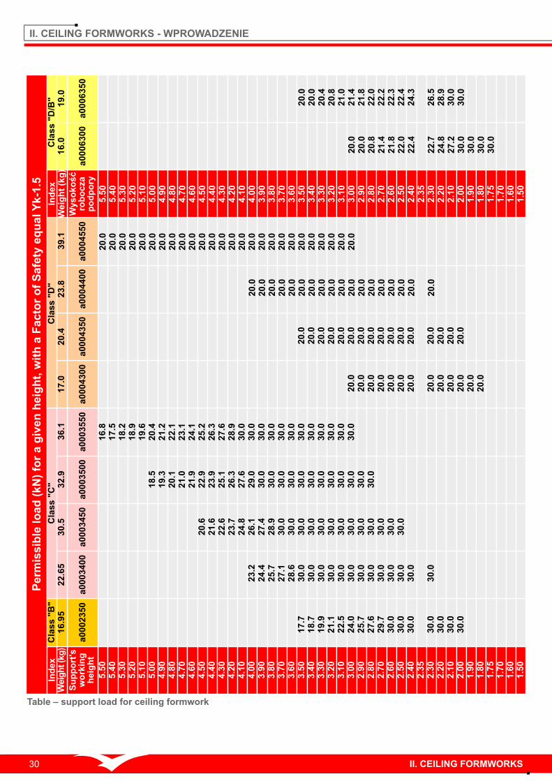
Table – support load for ceiling formwork
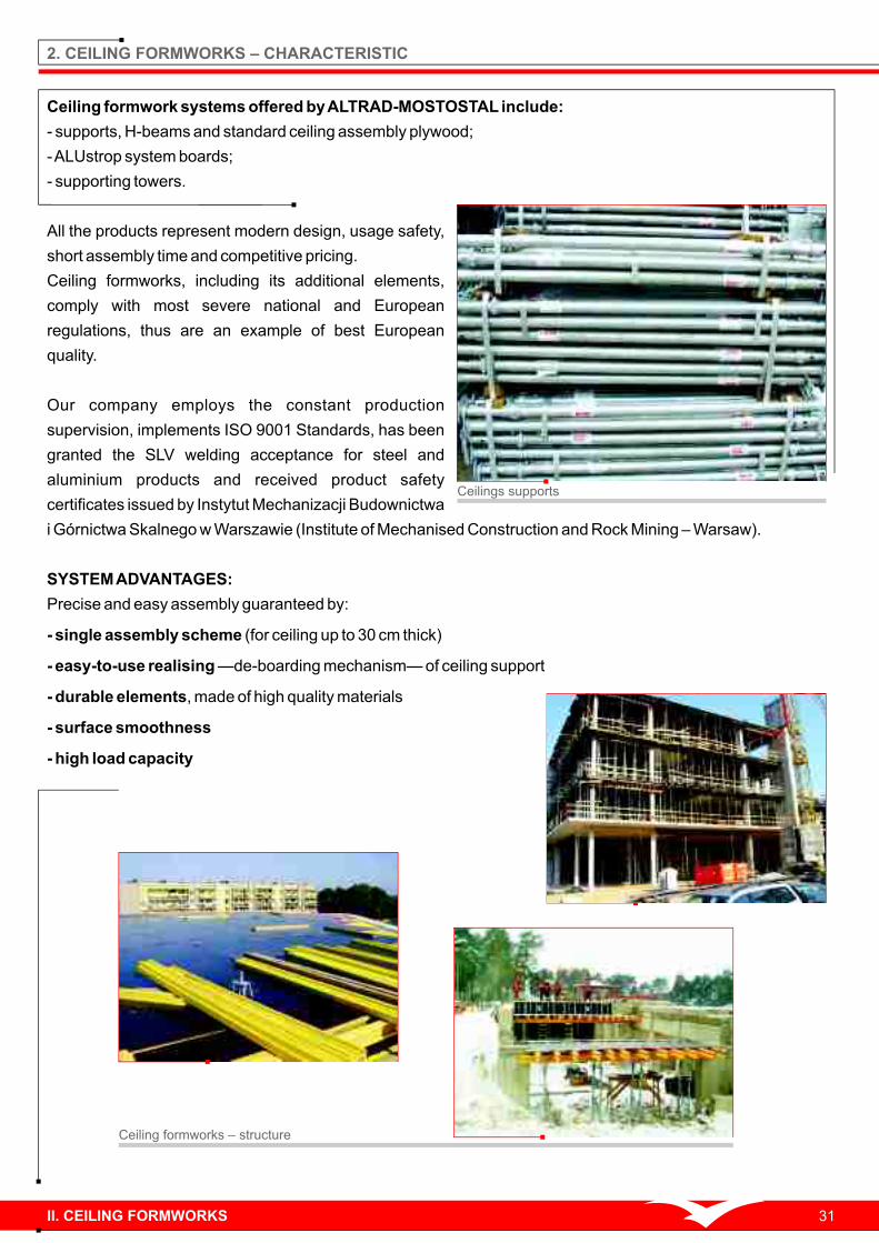
Ceiling formwork systems offered by ALTRAD-MOSTOSTAL include:
- supports, H-beams and standard ceiling assembly plywood;
- ALUstrop system boards;
- supporting towers.
All the products represent modern design, usage safety,
short assembly time and competitive pricing.
Ceiling formworks, including its additional elements,
comply with most severe national and European
regulations, thus are an example of best European
quality.
Our company employs the constant production
supervision, implements ISO 9001 Standards, has been
granted the SLV welding acceptance for steel and
aluminium products and received product safety
certificates issued by Instytut Mechanizacji Budownictwa
i Górnictwa Skalnego w Warszawie (Institute of Mechanised Construction and Rock Mining – Warsaw).
SYSTEM ADVANTAGES:
Precise and easy assembly guaranteed by:
- single assembly scheme (for ceiling up to 30 cm thick)
- easy-to-use realising —de-boarding mechanism— of ceiling support
- durable elements, made of high quality materials
- surface smoothness
- high load capacity
2. CEILING FORMWORKS – CHARACTERISTIC
Ceiling formworks – structure
Ceilings supports
II. CEILING FORMWORKS 31

STANDARD CEILING:
Its basic elements consist of steel supports and wooden
H-beams. Support's height can be adjusted in the range of
1482 mm up to 5500 mm. Wooden H-beams are available in the
length of 1800 mm , up to 5900 mm.
Ceiling supports are made of hot-dip zinc coated, anti-corrosive
steel pipes. This kind of corrosion protection guarantees high
resistance to environmental factors.
Wooden H-beams durability is guaranteed by means of
impregnation (H-beams are made by world's leading
manufacturers).
Ceiling formwork system means:
- easy assembly;
- work safety;
-low time expense;
- highly re-usable formwork set;
- economical solutions.
All of this adds to the profit of YOUR company.
Heads and H-beams are important elements of standard ceiling: the fork tongs spacing allows the safe
installation of one H-beams, while after turning the head by 90 degrees — two wooden H-beams. This system
allows to comet H-beams to any length without necessity of additional supports installation. The head is
installed inside the support by mounting the head mandrel in the top opening of the support.
Ceiling formwork application on the building site
H-beams on the cross head H-beams on the cross head – scheme
32 II. CEILING FORMWORKS
Supports application – staircase

Ceiling supports are basic elements of standard ceiling
formwork system and ALUstrop.
The supports represent wide range of height adjustment. The
adjustment is carried out in two stages:
a. in steps of every 10 cm and fitting of the G-hook in the
support mandrel at the desired height;
b. precise adjustment — in range of 10 cm, by turning the nut on
support mandrel. In this way we can precisely, with millimetre
accuracy, level the ceiling surface.
Wooden formwork H-beam Formworks – building site
Support application on the building site
Innovative G-hook solution, present in available
supports, allows quick formwork removal of ceiling
by simple support height reduction (by 3 mm) and
efficient disassembly.
At the formwork removal, with single hammer tap
or twist with available bar or bowstring, the G-hook
is turned up. The support mandrel has been
lowered and the ceiling thrust has been
"slackened". Only now the support mandrel can be
slightly lowered with L-hook.
One full turn (360 degrees) of the nut decreases or increases the formwork level by 1 cm.
Using ceiling supports we can set with lightning speed not only horizontal ceilings but also all the designed
surfaces with slopes in any directions.
In practice, the supports can be used at building site not only in the said system. They are also indispensable in
supporting and tensioning of lintels, beams, binders, balconies, TERRIVA and ACKERMAN ceilings and others.
II. CEILING FORMWORKS 33
Wooden formwork H-beam is glued with special resins for construction joints. The resins are approved by Glue
and Adhesives Institute Nordisk Limtrenemnd in Norway and German Forschungs und Materialprüfungsanstalt
Baden-Württemberg.
The whole H-beam is impregnated with formulation which guarantees durability in outdoor conditions – 5 years
minimum, indoor conditions — 20 years minimum.
Sequence of actions during support load reductionwith G-hook
G-hak
The support is fastened in tripod with special shifting lock what allows very fast engaging and disengaging the
elements without the necessity of screwing. Recommended proportion of tripods to supports number is 1:3.
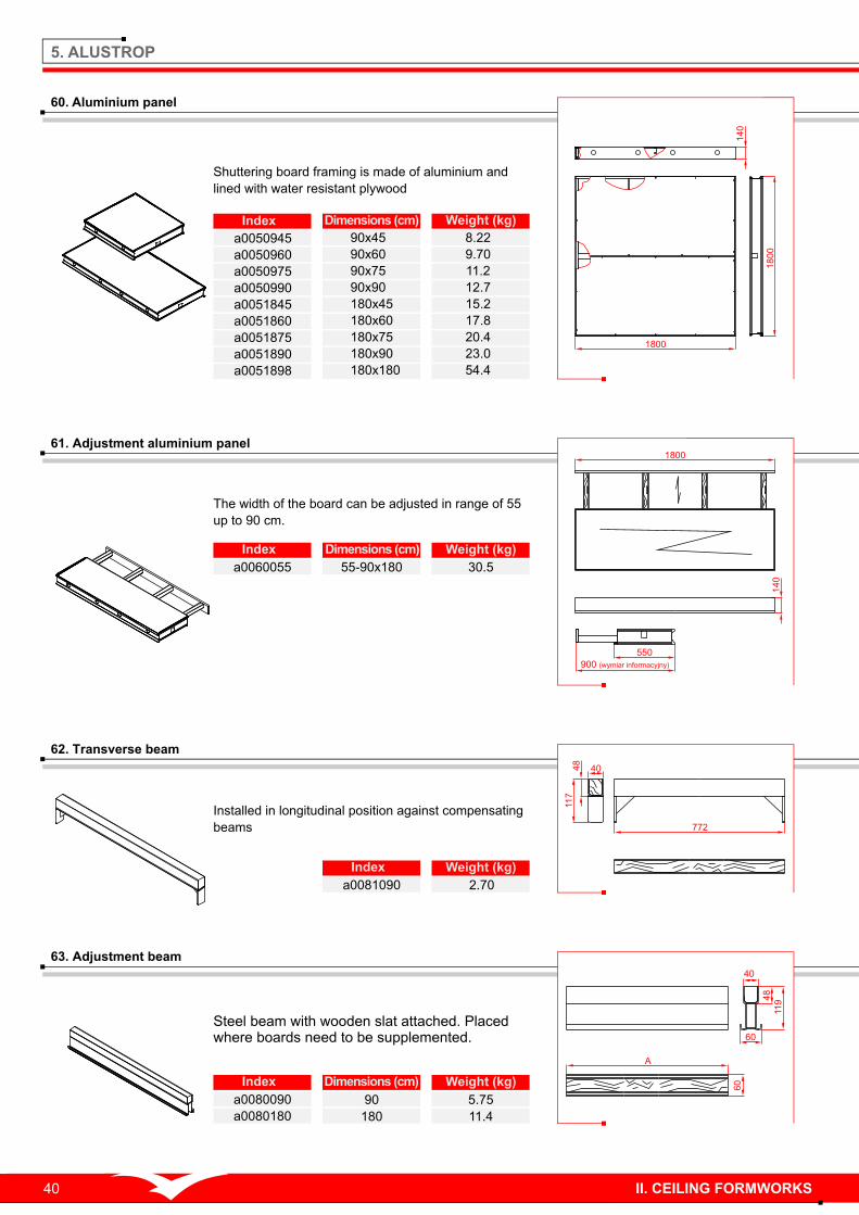
Post is an important and indispensable (from the Workplace safety point of view) formwork system element
we divide them into: rail posts, corner rail posts, universal rail posts. The posts are used as the protective
measure during construction.
Planks are used with the posts. Inserted into the
bearings for railing, they act as protective railings.
Depending on the needs, the post's structure allows it
to be attached to the ceiling edge or to the ceiling
formwork structure.
We offer three different kinds of posts. This allows the
customer to choose the optimum number of the posts.
Posts – three available models
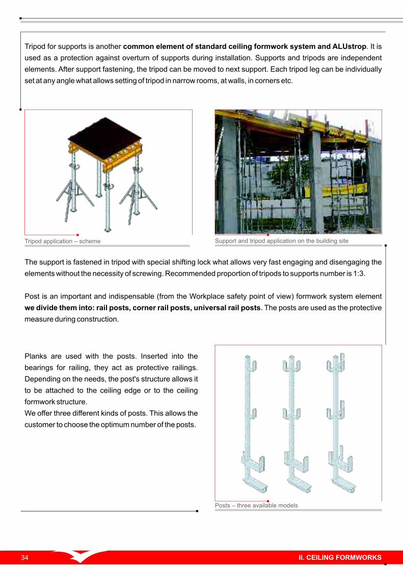
Tripod for supports is another common element of standard ceiling formwork system and ALUstrop. It is
used as a protection against overturn of supports during installation. Supports and tripods are independent
elements. After support fastening, the tripod can be moved to next support. Each tripod leg can be individually
set at any angle what allows setting of tripod in narrow rooms, at walls, in corners etc.
Support and tripod application on the building site Tripod application – scheme
34 II. CEILING FORMWORKS

The basic element of ALUstrop structure is an aluminium panel, available in different sizes. Wide range of
sizes, supplemented by adjustment shuttering boards, guarantees that the set will fit any ceiling. The gaps can
filled with adjustment boards, adjustment and transverse beams or square timbers. The boards can be
supported with building supports equipped with supporting heads. Maximum ceiling thickness is 50 cm.
Longitudinal and transverse girders, being an ALUstrop system elements, are used for boarding places with
poles made of reinforced concrete.
Innovative shape of framing profiles in the plywood assembly zone facilitates silicon preservation in the
gaps between profile and plywood.
Framing profile structure allows draining of the bleeding water from the boards contact places.
It secures profile's side surfaces from being soiled.
ALUstrop means:
2 – attractive pricing (economical with ceilings measuring above 100m );
– light structure;
– unhampered transport and storage (owing to light structure); 2 2 – slick assembly and disassembly – ok. 0.2 h/m ; for comparison – standard ceiling – ok. 0.55h/m ;
– tenacity of the elements (made of materials resistant to environmental factors);
– rotaryness of the hardware during construction;
– opportune smoothness of the obtained surface;
– pleasure of setting up and dismantling a formwork.
A
L
U
S
T
R
O
P
ALUSTROP – aluminium ceiling formwork
Aluminium panels supported by supports
ALUstrop on building site ALUstrop board during assembly
II. CEILING FORMWORKS 35
ALUstrop is supplemented by an adjustment
shuttering board that, contrary to standard
aluminium panel, has it's width adjustable in the
range of 55 cm to 90 cm.
900 (wymiar in
formacyjny)
140
550
1800

S10 SUPPORTING TOWER — relocates vertical loads
Tower's structure consists of steel frames with a support distance of 1.0 x 1.0 m and height stepped every 0.5 m.
Infinitely variable adjustment of tower's height to desired values is obtained by expanding the footings and
adjustable heads.
Tower's stiffness in both perpendicular directions is guaranteed by the rule of basic frame 90° rotation during
tower's assembly, and by vertical bracings that stiffen subsequent frames.
Please remember that bracings merge the structure into inseparable piece, which is particularly important
when considering vertical, crane transport of the tower.
Supporting tower is used during:
- boarding of monolithic building structures;
- supporting prefabricated elements of building structures;
- realization of supporting structures for working platforms;
- realization of gang-boards.
All S10 supporting tower's structure elements are hot-dip zinc coated.
36
S10 supporting tower – schemeS10 tower – realization of a monolithic building structure formwork
placed atop
not placed atop
For a tower
5.50 52.0 43.0
41.0
52.4
51.0
48.0
please consult the manufacturer
51.6
53.0
53.0
52.4
50.4
7.50
5.50
7.50
12.50
20.00
Set-up height [m] Without wind load
Permissible load for a single stand [kN]
With wind load
S10 tower load chart

3. BASE ELEMENTS OF STANDARD CEILING AND ALUSTROP CEILING
Weight (kg)IndexIndex Weight (kg)Dimensions (cm)
51. Ceiling support (B, C, D)
52. Tripod for supports
Supports are made of steel pipes
secured with hot-dip zinc coating.
Serves as a protection against overturn of supports
during boarding.
a0025001
84
5
85
0
98 7.40
Weight (kg)Index Class
a0002350 B
a0003400 C
a0003450 C
a0003500 C
a0003550 C
a0004300 D
a0004350 D
a0004400 D
a0004550 D
a0006300 D/B
a0006350 D/B
Class B
Class C
Class C
Class C
Class C
Class D
Class D
Class D
Class D
Class D/B
Class D/B
16.9
22.6
30.5
32.9
36.1
17.0
23.0
24.0
36.0
15.6
17.5
II. CEILING FORMWORKS 37
18
00
- 5
90
0
Assembling support into tripod – scheme

4. STANDARD CEILING SYSTEM
56. Intermediate head
o15
4240.5
15 100
Ø70
47
65
152
Serves as intermediate beam support. Allows set-up
with required spacing of ceiling supports.
Weight (kg)Index Dimensions (cm)
a0020002 10x10.4 0.86
53. Wooden formwork H-beam
Index Weight (kg)Dimensions (cm)
a0010130
a0010165
a0010180
a0010245
a0010250
a0010265
a0010290
a0010330
a0010360
a0010390
a0010450
a0010490
a0010590
7.16
9.01
9.83
11.7
11.9
12.7
13.9
15.8
17.2
18.7
21.6
25.2
28.3
130
165
180
245
250
265
290
330
360
390
450
490
590
- full section beam of
invariable form
- permissible bending
moment – 5.0 kNm
- permissible distributed
load – 11.0 kN
- beam web made of triple-
layered glued panel
- dźwigar okuty
55. Cross head
Provides the support for ceiling formwork. The fork
tongs spacing allows the safe installation of one beam,
while after turning the head by 90 degrees – two
beams.
22
0
18
4
99
140
Ø14
Ø38
150
17
0
Weight (kg)Index Dimensions (cm)
a0020001 22x14 2.61
54. Formwork plywood
Index Weight (kg)Dimensions (mm)
a0998155
a0998250
a0998300
a0999150
a0999200
a0999250
21x1550x1550
21x1250x2500
21x1500x3000
21x500x1500
21x500x2000
21x500x2500
35.7
46.5
61.2
11.1
14.7
13.3
Plywood is 21 mm thick, smooth finish on both sides,
water resistant, protected with resin coating.
12
00
250021
ok
uw
an
e
38 II. CEILING FORMWORKS
200
80
40
27
+L
5 -

58. Rail post
110
65
30
157
220
50
0
70
5
13
18
All types of posts secure the work during boarding.
Maximum post spacing is 2 m.
Weight (kg)IndexName
6.98
7.70
8.43
a0035130
a0036130
a0038130
rail post
corner rail post
universal rail post
Weight (kg)Index Dimensions (cm)
5.97a0026000 40x53
57. Beam clamp
35
10
0
240400
30
0
160
Allows precise boarding of binders, beams, lintels etc.
Provides horizontal shift regulation, which allows
simple and fast boarding setting along straight lines or
according to the required shape.
Weight (kg)Index Dimensions (cm)
59. Top wall bracket
a0030000
Ideal for setting up the formwork for far edges of the
ceiling on existing walls or binders.
90
40
35
70
46
01
50
900
125
100
100
100
90 3.90
II. CEILING FORMWORKS 39
Weight (kg)Index
a0050945
a0050960
a0050975
a0050990
a0051845
a0051860
a0051875
a0051890
a0051898
90x45
90x60
90x75
90x90
180x45
180x60
180x75
180x90
180x180
Dimensions (cm)
8.22
9.70
11.2
12.7
15.2
17.8
20.4
23.0
54.4
5. ALUSTROP
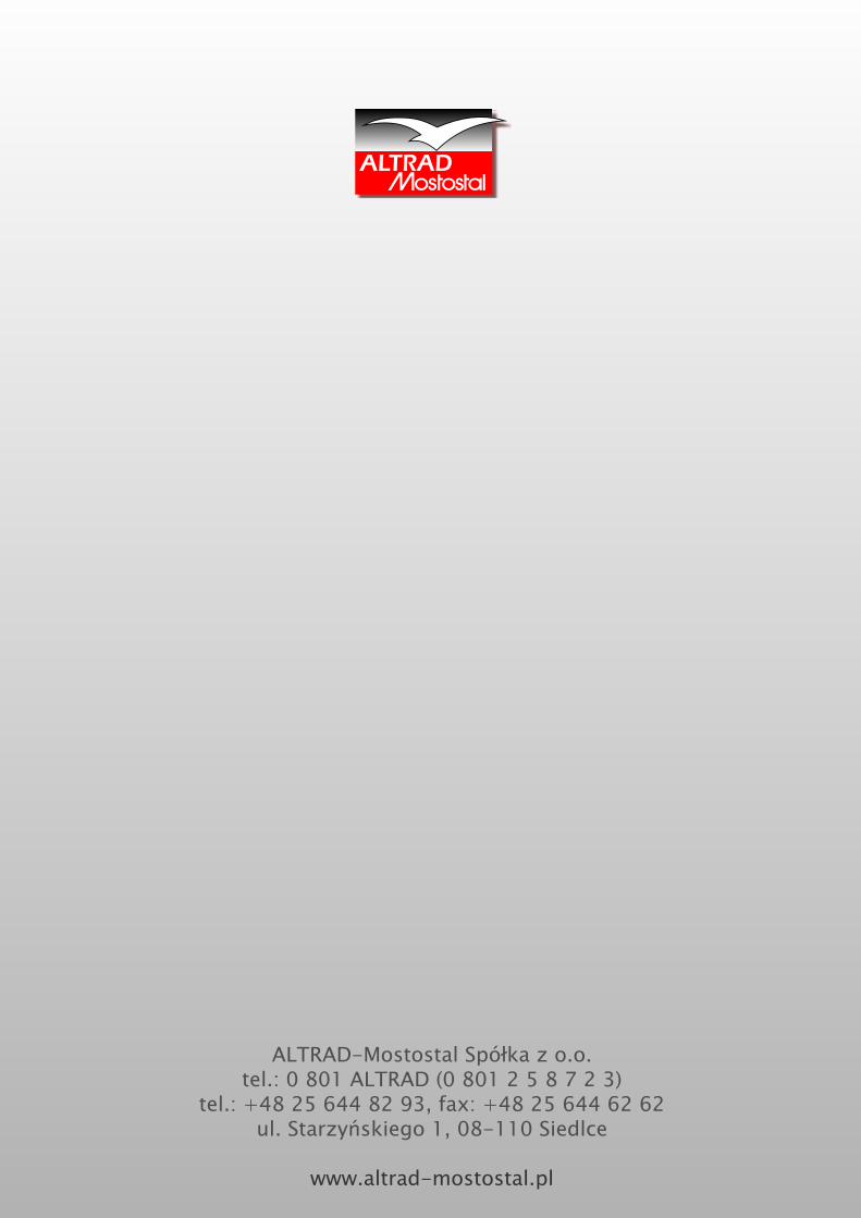
60. Aluminium panel
Shuttering board framing is made of aluminium and
lined with water resistant plywood
62. Transverse beam
Installed in longitudinal position against compensating
beams
Weight (kg)Index
a0081090 2.70
Weight (kg)Index Dimensions (cm)
61. Adjustment aluminium panel
a0060055 55-90x180
The width of the board can be adjusted in range of 55
up to 90 cm.
30.5
63. Adjustment beam
Index Weight (kg)Dimensions (cm)
a0080090
a0080180
90
180
5.75
11.4
Steel beam with wooden slat attached. Placed where boards need to be supplemented.
40
48
119
60
60
A
1800
18
00
14
0
40 II. CEILING FORMWORKS
550
900 (wymiar informacyjny)
1800
14
0
48
117
40
772

65. Corner supporting head
Allows very tight connection of shuttering boards with walls.
Ø38 140
84.536
8
72
110
Weight (kg)
a0070002
Index
1.96
64. Steel supporting head
Placed inside the support, serves as a support for aluminium ceiling panels
36
8
140
14
0
38
140
Ø38
Weight (kg)
a0070000
Index
2.28
66. Bearing for railing
Serves for attaching working platform's posts.
140
14
0
49
0
15
0
Ø38
Weight (kg)
a0072000
Index
3.24
67. Head support shoe
Placed on heads. Serves for placing square timbers supplementing the formwork.
Weight (kg)
a0075000 0.59
Index
II. CEILING FORMWORKS 41
68. Security for the toeboard
Placed on working platform's post. Holds
toeboard in place. 60
Ø1268
Ø48.3
167
Weight (kg)
a0078000
Index
0.40
60
39
170
85

6. S10 SUPPORTING TOWER
69. Base frame
Installed on top and bottom of the tower. Stiffens the
structure vertically.
Index Weight (kg)
a0040100
10
00
44
0
33
0
1000
33
0
17.4
Weight (kg)Index
a0081090 90
71. Vertical bracing
Stiffens tower sides and connects frames during crane
transport.
Index Weight (kg)Dimensions (cm)
a0042125 125 Ø38
1300
1250
2,50
70. Basic frame
Stiffens the structure horizontally. Four basic frames are mounted at the height of 1 m.
Weight (kg)
a0041050
Index
7.70
72. Adjusted footing
Index
e511206
Weight (kg)
4.30
Serves for compensation of ground faults. Adjustment
range – 400 mm.
Rd 38x8
150
600
200
150
200
42 II. CEILING FORMWORKS

75. Normal coupling
Index
e581119
Weight (kg)
0.80
Connects pipes Ø=48.3 at right angle.
42
42
54
.6
Ø48.3
Ø48
.3
74. Transport security
Index
a0040000
Weight (kg)
0.10
Secures foot and head from slipping out of
frames
73. Threaded cross head
Index
e642210
Weight (kg)
8.14
Provides support for ceiling formwork. Adjustment range
– 350 mm.
76. Rotary coupling
Connects pipes Ø=48.3 pat any angle.
II. CEILING FORMWORKS 43
60
R864
R8
15
4
87
R28
46
22
250
60
0
200
19
5
16
5
Rd 38x8
77. Universal pipe
Used for stiffening the towers (L = 1 ÷ 6 mb).
Weight (kg)Index Dimensions (cm)
e440510
e440520
e450530
e440540
e440550
e440560
3.56
7.12
10.7
14.2
17.8
21.4
100
200
300
400
500
600
L
Ø48.3x3.2
Index
e581319
Weight (kg)
1.20
74

Weight (kg)Index
Weight (kg)Index
a0081090 90
Ideal for economical storage and transportation of formwork elements. Adapted for
forklift and crane transportation.
As the set with module pallet. Used for storage of small elements. May be used as
an additional or supplemental element of module pallet.
Index Weight (kg)Dimensions (cm)
Index Weight (kg)Dimensions (cm)
79. Module basket
e822800
e822900
40.2
30.4
560
1060
59
08
00
20
0
128x88
108x68
Index Weight (kg)Dimensions (cm)
Ideal for transportation of formwork elements. Adapted for forklift and crane
transportation.
80. Basket pallet
e822808 69.7128x88
81. Anti-adhesive liquid
III. ACCESSORIES
78. Module pallet
Oil based anti-adhesive liquid for lubrication of shuttering boards' surfaces on the
inside of the formwork. Protects against concrete's sticking to formwork.
Index
a2599001
Weight (kg)
30.0
44 III. ACCESSORIES
880
82
5
680
800
1280
1080
1200
880
82
5680
800
12801080
1200

System szalunków ALTRAD-Mostostal - budowa ALTRAD-Mostostal boarding system – Media-Markt construction site in Warsaw

IV. ROTAX SUPPORTING TOWER
ALTRAD-Mostostal offers two types of supporting towers: S10 tower and
tower based on ROTAX system.
TWO SYSTEMS, MULTIPLE POSSIBILITIES
1. S10 supporting towers' structure consists of steel frames with
a support distance of 1.0 x 1.0 m and height stepped every 0.5 m.
2. Supporting towers based on ROTAX scaffoldings can be assembled
using steel elements with support distance starting from 0.73 x 0.73 m
(other distances can be obtained depending on system transoms'
length) and height stepped every 0.5m.
3. One of S10 towers' advantages over ROTAX based towers, is their
faster assembly.
4. It is possible to connect multiple towers when constructing ROTAX
towers. In case of S10 towers, the connection of multiple towers requires
the use of universal pipes and cross couplings.
5. ROTAX tower's structure allows assembly of steel brackets (0.36 m;
0.73 m; 1.09 m), which are used as working platforms. The connection is
realized with the use of stiffeners.
46 IV. ROTAX SUPPORTING TOWER
Inspection platform – application example of ROTAX tower and a staircase

V. STAIRCASES (ROTAX, FACADE)
ALTRAD-Mostostal additional elements of the offer consist of incredibly economical staircases, which
improve building construction and finishing works.
ROTAX staircases
Staircases based on ROTAX and Mostostal PLUS scaffoldings.
Used for communication between building's levels. Realized as
single- or multi-speed.
Staircases can act as communication plumb-lines attached to the
scaffolding's facade or as independent structures properly
anchored to existing objects.
2572
12
00
0
13
50
0
1572
20
00
20
00
20
00
20
00
20
00
20
00
10
00
47V. STAIRCASES (ROTAX, FACADE)

Mostostal PLUS staircases
Choice of a proper scaffolding type for staircases is crucial in
case of anchoring the staircases to the facade of existing
scaffolding.
Both staircase types have common elements: stairs, internal
stair-rails.
Typically, external staircase is mounted in the bay
measuring 3.07 m or 2.57 m.
Presented structures are used in cases where there is a
need to gain access to a particular building level, where
formwork assembly or concrete filling is conducted.
13
50
0
1572
20
00
20
00
20
00
20
00
20
00
20
00
15
00
2572
12
00
0
48 IV. ROTAX SUPPORTING TOWER
ALTRAD-Mostostal Spółka z o.o.tel.: 0 801 ALTRAD (0 801 2 5 8 7 2 3)
tel.: +48 25 644 82 93, fax: +48 25 644 62 62ul. Starzyńskiego 1, 08-110 Siedlce
www.altrad-mostostal.pl