w05 – basics of setting up profinet-pa networks · pdf filew05 basics of setting up...
TRANSCRIPT

W05 Basics of setting up
PROFIBUS-PA networks
Martin RuckSiemens
Jason Nicholl Phoenix
Kris HardakerUnited Utilities

Basics of setting up a Profibus PA Network
1. What is Profibus PA
2. Benefits of using a Fieldbus
3. System Components
4. Profibus PA Rules
5. Network Configuration
Agenda
Demonstration Network Configuration• Jason Nicholl - Phoenix
• Pactware FDT/DTM
• Kris Hardaker - United Utilities• Simatic PDM EDD
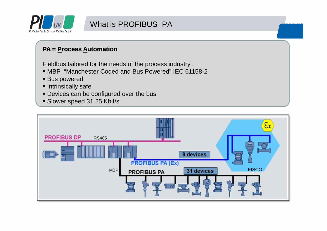
PA = PA = PProcess rocess AAutomation utomation
Fieldbus tailored for the needs of the process industry :MBP “Manchester Coded and Bus Powered” IEC 61158-2Bus poweredIntrinsically safeDevices can be configured over the busSlower speed 31.25 Kbit/s
What is PROFIBUS PA
FISCO
RS485
MBP

Why Use a Fieldbus
Normal Operating Range 4- 20mA
Signals below 4mA indicate instrument failure
0mA indicate open circuit
Signals above 20mA indicate instrument failure
4 – 20mA
Scaling and Accuracy
Fieldbus Motivation
Profibus PA
4- 20mA

Benefits of Using a Fieldbus
Reliable data from Field devicesMore accurate readings with regards to resolutionMore diagnostics to prove instrument functionalityData presented in same formatRemote configurationNuisance alarms. Good
Unchecked
Configuration error
Fault
Maintenance required
Advance maintenance warning
Process error
Communication interrupted
Simulation
Communication good
Device has no diagnosticsDevice passive or notassigned

System Components
Controller
PROFIBUS DP Slaves
PROFIBUS PADP/PA-Link/Coupler
Industrial Ethernet / Fast Ethernet
Profibus DP Physical LayerModified RS485speeds between 9.6kbit/s and 12Mbit/s
Profibus PA Physical LayerManchester Encoded Bus Powered (MBP) (IEC 61158-2)31.25kbits/s

Converting from Profibus DP to PA
Coupler Link + CouplerLow speed connection High speed connection
# Manufacturer specific e.g. PF SK1 93.75Kbits
•Lower Cost•Profibus DP Side is slowed to 45.45kbaud #•Coupler is Invisible to the network•Can only have 124 devices
(DP &PA addresses are combined)
•Profibus DP side can be any speed (12 Meg)•Link Module takes one DP address•Up to 5 couplers•Can have 1000’s devices •Can have faster update times
Simple monitoring Control
4 5 6 7 8 9 4 5 6 4 5 6
5 6
System Components
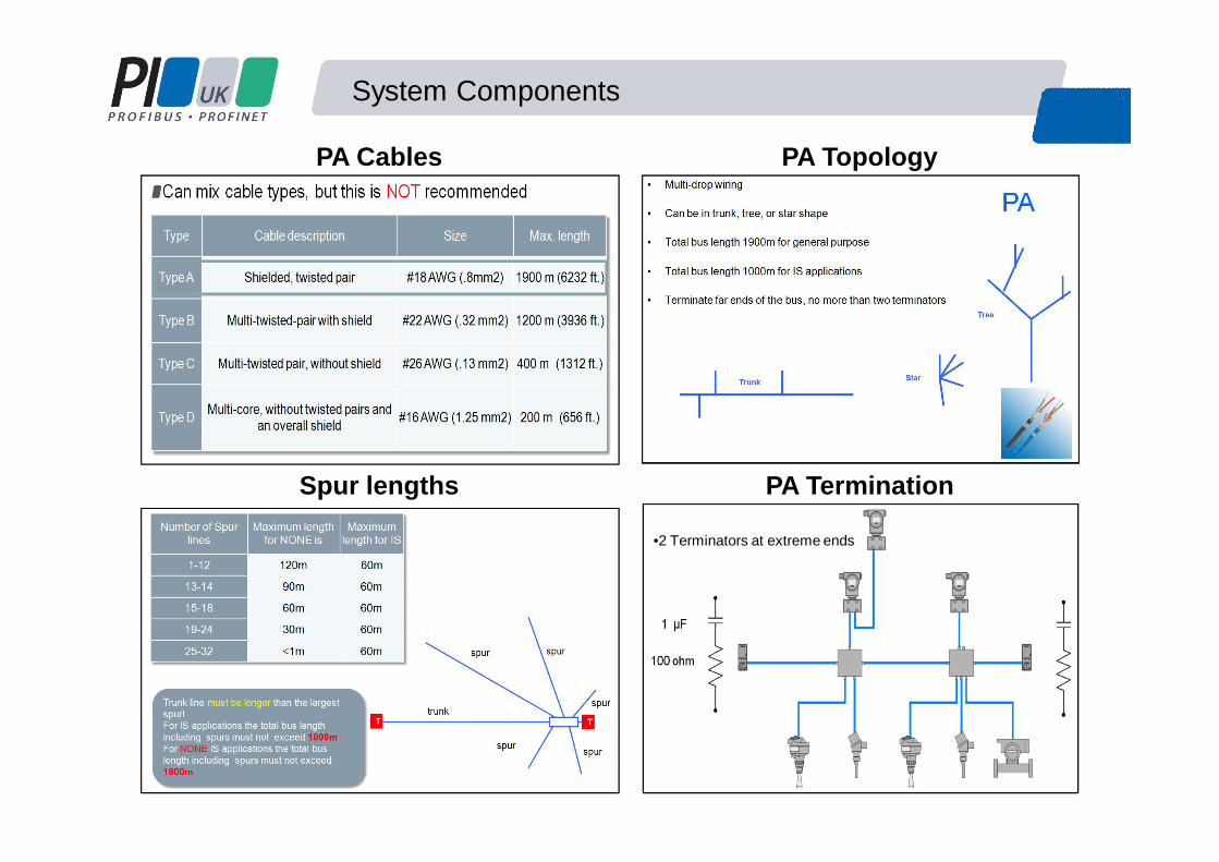
PA TopologyPA Cables
Spur lengths PA Termination
•2 Terminators at extreme ends

System Components
M12 Connectors T Junctions
Junction Boxes Active Field Distributors

Add new devices
PROFIBUS PA Automatic bus termination
AFD
Bus termination
Enhance lineEnhance ringM
There is no need to reserve spare ports of the AFDs !
AFDAFDAFD AFD
DP/PA Link
Profibus PA Active field distributors AFD

Profibus PA Active field distributors AFD
Increasing availability and simplifying installationRobust Network

Design, Installation and Commissioning12
1. Spur Lines and Lengths must correlate
2. Use Class A, PROFIBUS PA cable and use only one cable manufacturer
3. Total cable length depends on coupler used, can not exceed 1900 meters for none IS
4. Ensure that there is more than 9V at each slave
5. Total number of devices depends on the current draw.
6. Terminate at the extreme ends of the segment
7. Follow recommended grounding practices
8. Intrinsically Safe (IS) design affects maximum spur lengths and total length.
9. Ensure spur length does not exceed the trunk line length
Network Design Tools
•Segment Voltage•Cycle times

Configuration - GSD Files (General Station Data)13
Controller
PROFIBUS PA
Profibus Configuration Tool
The GSD File holds information about the Profibus Device
•Profibus Ident•Supported Baud rates•Diagnostics supported•Module type and data Length
Cyclic CommunicationsDevice -Value / Status
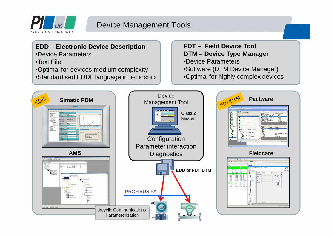
Device Management Tools
Simatic PDM
AMS
Pactware
Fieldcare
ConfigurationParameter interaction
Diagnostics
Device Management Tool
Class 2 Master
PROFIBUS PA
EDD or FDT/DTM
EDD – Electronic Device Description•Device Parameters•Text File•Optimal for devices medium complexity•Standardised EDDL language in IEC 61804-2
FDT – Field Device ToolDTM – Device Type Manager•Device Parameters•Software (DTM Device Manager)•Optimal for highly complex devices
Acyclic CommunicationsParameterisation
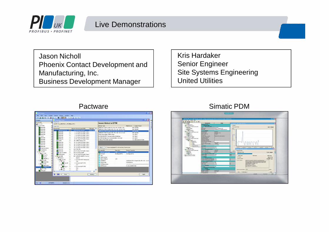
Live Demonstrations
Pactware Simatic PDM
Kris HardakerSenior EngineerSite Systems EngineeringUnited Utilities
Jason NichollPhoenix Contact Development and Manufacturing, Inc.Business Development Manager

Contact
Basics of setting up a Profibus PA Network
Jason NichollBusiness Development Manager Phoenix Contact Development and Manufacturing, IncI/O and Networks Business Unit, AmericasTel: 1-800-888-7388 x3720Email: [email protected]
Kris HardakerSenior EngineerSite Systems EngineeringUnited UtilitiesT: 01925 731037 (internal 31037)Email: [email protected]
Martin RuckProduct ManagerProcess InstrumentationSiemens Industry GB&IMobile: +44 (0) 7808 824913Email: [email protected]
Thank you for your time