w1 1 w14 w15 w12 'y w16 w17
TRANSCRIPT

_ US005376924A
United States Patent [19] [11] Patent Number: 5,376,924 Kubo et al. [45] Date of Patent: Dec. 27, 1994
[54] FIRE SENSOR [56] References Cited
75 I T _ K n h f U.s. PATENT DOCUMENTS
[ 1 mentors. ritiuiialiul'i?’ghmkj??; ‘Zia in 3,765,842 10/1973 Purt ............................... .. 340/633X NY’ 8 ’ g ’ 4,088,986 5/1978 BOllCher 340/634X
° aPan 4,630,03812/1986 Jordan . . . . . . . . . . . . . . . .. 340/632
' 4,778,113 10/1988 Jewettetal. . 340/632X
[73] Assignee: Hochiki Corporation, Tokyo, Japan 5,053,754 10/1991 Wong . . . . . . . . . . . . . . . . .. 340/632
5,146,209 9/1992 Beghelli ........................ .. 340/632X
Primary Examiner-John K. Peng Assistant Examiner-Tim Johnson Attorney, Agent, or Firm—Sughrue, Mion, Zinn, Macpeak & Seas
[57] ABSTRACT A ?re sensing method and apparatus for detecting a ?re based on the detection of a hydrocarbon gas produced before ?re ignition and the detection of a second ?re indicating phenomenon. Such other phenomenon may comprise the detection of temperature, radiation or combustion product gases. The detection of hydrocar
[21] Appl. No.: 950,470
[22] Filed: Sep. 24, 1992
[30] Foreign Application Priority Data Sep. 26, 1991 [JP] Japan ................................ .. 3-247213 Sep.26,1991 [JP] Japan ................................ .. 3-247214
Sepl 26, 1991 [JP] Japan ................................ .. 3-247215 Sep. 26, 1991 [JP] Japan ................................ .. 3-247216 Sep. 26, 1991 [JP] Japan ................................ .. 3-247217
[51] Int. Cl.5 ........................................ .. G08B 17/10 [52] US. Cl. .................................. .. 340/632; 340/634;
73/2331 [58] Field of Search ..................... .. 340/632, 633, 634;
73/2321, 23.31, 23.2
bon gas may generate a pre-alarm condition which permits the use of higher sensitivity conditions for the second ?re indicating phenomenon.
22 Claims, 13 Drawing Sheets
W13 FIRE ALARM APPARATUS
W1 1 W14 W15 HYDROCARBON PREALARM PREALARM GAS SENSOR JUDGMENT OUTPUT
__n I
W12 ‘Y W16 W17 FIRE
CO2 SENSOR I ' JUDGMENT 7 FIRE ALARM
—__ I
W18 ENVIRONMENT
= CONDITION ALARM

US. Patent Dec. 27, 1994 Sheet 1 of 13 5,376,924
FIG. 7
N1 ’ N 2 W 3
HYDROCARBON FIRE JUDGMENT GAS sENsoR SECTION ' ALARM SECTION
N13 FIRE ALARM APPARATUS
W1 1 W14 W15 HYDROCARBON PREALARM * _ PREALARM GAS SENSOR ! JUDGMENT * ' OUTPUT
W12 {y W16 W17 FIRE
002 SENSOR I JUDGMENT FIRE ALARM
___ I
W18 ENvIRoNMENT
= CONDITION ALARM

US. Patent Dec. 27, 1994 Sheet 2 of 13 5,376,924
SAMPLE TEMP. [°C]
2: .. com . can . oov .. com .. cow ,
SAMPLE THERMAL REAC. [1.1V]
owl o T .
@5 £55: _ ms:
" _
_ N 2255: azm?gzw w M250 zcCo?E 221$; m 2254mm oHzzwEoxw
w mSmsu .Qzm;
, m , iv‘ 5
5mm; E 52w; 5 m $2 :65;
m. .QI
cow. 5
3 T
L.
oaT . Owl l cw! l. O?! . CNI
CHANGE IN WEIGHT [76]

US. Patent Dec. 27, 1994 Sheet 3 of 13 5,376,924
a: a: . 8. 2: 8 3 3 ON JII N;
“b b q - _ . _ _ _. o
_ . .
2: 5E: . = _ .
m3 2 _ 7 .
mm 3
I 1
coooow
Q .QI
US. Patent Dec. 27, 1994 Sheet 4 of 13 5,376,924
- - -
-
oo
oo
oN
oo om
ov b
-
om __»
ow
I n
-
.
Al N\:
Mm mo
32o
oooo
(gm. m .QE
3
ow
m:
N"
o
ooooo_ oooooN ooooom ooooow oooooo oooooo ooooow IYIIIITI‘IITIIIIIYfrIIIIIIIIuIIYTTI-[IIII
V‘ 888 . $22232

US. Patent Dec. 27, 1994
HYDROCARBON GAS IS SENSED ‘.7
SET PREALARM FLAG AND OUTPUT PREALARM
4
C02 DENSITYZDZ ?
Sheet 5 of 13 5,376,924
FIRE ENVIRONMENT IS DETERIORATED
US. Patent Dec. 27, 1994 Sheet 6 of 13 5,376,924
3
S U 5
W M 1.. M T
on W M R N.
A R A EN P AT. L M0 P .LU A NI A AP OT.
F:| E RIM
M RU Dn ID R P0 1 VNA A F. NOL .L ELCA
A
E v V a
R I
F v 4
w m1 T
AENL H ILM M AG EG Enu RD RU TIU PJ FJ I I
I N 1—
7 W 0R Dn _
BO 0 I RS 8 _
AN N . CE E . 0S 8
6 ms 2
YA 0
Cl! HG
PREALARM OUTPUT
FIRE ALARM APPARATUS
W 14
PREALARM JUDGMENT
FIRE ALARM
7
FIRE JUDGMENT
FIG. 8
W I 1
HYDROCARBON GAS SENSOR
RADIATION SENSOR
US. Patent Dec. 27, 1994 Sheet 7 of 13 5,376,924
H6. 9
" s1 1
HYDROCARBON GAS IS SENSED ?
SET PREALARM FLAG 5 AND OUTPUT PREALARM
RADIATION INTENSITY LEVEL
2H1 ?
RADIATION INTENSITY LEVEL
2H2 ?
US. Patent 0 Dec. 27, 1994 Sheet 8 of 13 5,376,924
H5. 70
MASS DATA ALARM SPECTROMETRY PROCESSING CONTROL SECTION SECTION SECTION
FIG. 77 ABUNDANCE }
800000 -
700000 -
600000 -
500000 -
400000 -
300000 -
200000 -
100000 —

US. Patent Dec. 27, 1994 Sheet 9 of 13 5,376,924
NE
3 m .DI
o 1882 .832 S253 283 5825 -888 .882 I cccccc
NE
cw
. N“ .mI
- cccccp . cccccw I cccccm . ccccc< . cccccm Tcccccc I cccccN I cccccm cc
US. Patent Dec. 27, 11994 Sheet 10 of 13 5,376,924
FIG. 74 [v 31
CO2 SENSOR
32 W 34A N 35
N ‘ COMPARISON FIRE OUTPUT C0 SENSOR SECTION SECTION
[V 33
02 SENSOR
US. Patent Dec. 27, 1994
FIG.
5,376,924 Sheet 11 of 13
76 W 31
CO2 SENSOR W 348 W 35
COMPARISON FIRE OUTPUT SECTION SECTION
W 33
O2 SENSOR
CO2 DENSITYZA ?
O2 DENSITYéC ?
81b
YES 82b
YES S3b
FIRE ALARM

US. Patent Dec. 27, 1994 Sheet 12 of 13 5,376,924
W 32
C0 SENSOR W 340 N 35
COMPARISON I FIRE OUTPUT SECTION SECTION
/V 33
02 SENSOR
C0 DENSIIYZB ?
YES
S20
FIRE ALARM S30

US. Patent Dec. 27, 1994
FIG. 20 /"
CO2 SI \lSOR - W 340
COMPARISON SECTION
/V 32
CO SENSOR
FIG. 27
YES
YES
Sheet 13 0f 13
CO2 DENSITYZA ?
S2d
CO DENSITYZB ?
5,376,924
[V35 FIRE OUTPUT SECTION
FIRE ALARM

5,376,924 1
FIRE SENSOR
BACKGROUND OF THE INVENTION
The invention relates to a ?re sensing method and a ?re sensor apparatus that judges the existence of a ?re by sensing gas produced at the time of the ?re. With conventional ?re sensing methods and ?re sen
sor apparatuses, it is a basic idea that the existence of a ?re is judged by detecting one or more of the various products of the ?re, such as smoke, heat or gas caused by ?re, and that upon such detection a ?re alarm will be generated. conventionally proposed combination ?re sensors involve various sensors, such as a CO gas sen sor, a humidity sensor, and a temperature sensor. The more complicated sensors are designed to infer the level of danger in ?res and gas leakages by applying fuzzy inference. However, where non-gas criteria are used, unacceptable delays occur in detecting the existence of a ?re. Even where the ?re is detected by sensing a gas such
as CO; gas and CO gas, both of which are produced in the combustion process, the detection is made by com paring the gas density with a predetermined threshold level. However, such conventional ?re sensors are de signed to detect CO2 gas or CO gas produced in the combustion process after ignition. Typically, when the C0; or CO level reaches a threshold that results in the existence of a ?re to be judged, the ?re has already grown intense and ?ames have become widely spread. Accordingly, the conventional sensor has the danger ous problem that the identi?cation of the existence and location of a ?re will be delayed.
Further, the mere improvement in ?re detection sen sitivity to achieve early location of ?res creates the problem of erroneous alarms. For highly sensitive de vices, increases in CO2 gas due to cigarettesmoke or a like non-?re phenomenon cannot be distinguished from increases in CO2 gas due to a ?re.
SUMMARY OF THE INVENTION
The invention has been made in view of these con ventional problems. Accordingly, an object of the in vention is to provide a ?re sensor which allows early sensing of a ?re by monitoring gases, and also is capable of minimizing erroneous alarms. A fire sensor in accordance with a ?rst embodiment
of the invention comprises a hydrocarbon gas sensor that detects hydrocarbon gas produced at a very early stage of a ?re before ignition and a combustion detector for detecting an occurrence of ?re in response to an output of the gas sensor. A ?re sensor in accordance with a second embodi
ment of the invention comprises a hydrocarbon gas sensor that detects hydrocarbon gas produced at a very early state of a ?re before ignition, a combustion gas sensor that detects gases produced or changing due to the combustion process after ignition, a prealarm judg ment section that judges detection of the hydrocarbon gas by the hydrocarbon gas sensor and then outputs a prealarm, and a ?re judgment section that judges the ?re from an increase or decrease in the gases detected by the combustion gas sensor after the detection of the hydrocarbon gas has been judged by the prealarm judg ment section and then outputs a ?re alarm.
In accordance with yet another feature of the inven tion, there is a ?re sensor that uses a combustion gas
5
15
25
30
45
50
55
65
2 sensor that is operative to detect any one or more of CO2 gas, CO gas, or 02 gas.
In a further feature of the invention, a ?re judgment section judges a ?re when, after the detection of hydro carbon gas has been judged, the CO2 gas or CO gas detected by the combustion gas sensor has increased drastically or the 02 gas detected by the combustion gas sensor has decreased drastically. As a further feature of the invention, the ?re judg
'ment section warns that the environment is being deteri orated when a change in the combustion gases has been detected by the. combustion gas sensor, even though there has been no detection of hydrocarbon gas suf? cient to create a prealarm condition, the change being an increase in CO1 gas or CO gas or a decrease in 02 gas. Yet another object of the invention is to provide a
combination ?re sensor that can surely judge a ?re by simple processing while detecting at least two gases out of a plurality of gases to be detected, which gases have been speci?ed from the results of repeated study and analyses made on gases produced during combustion tests from the viewpoint of thermal decomposition pro cess of burning substances. The ?re sensor constructed in accordance with the
above features of the invention can locate a ?re at an early stage of the ?re by sensing the presence of hydro carbon gas, based on the fact that in?ammable hydro carbon gas is produced as a sign of ignition since hydro carbon gas is not usually present in the air and is in very small quantities if present.
Further since hydrocarbon gas is not produced as a result of smoking a cigarette or alike non-?re phenome non, a ?re is located by continuity in time between the detection of hydrocarbon gas and the detection of, e.g., CO2 gas or CO gas. Therefore, even if ?re detection sensitivity is high, an increase in the CO; or CO content due to a ?re can be distinguished from an increase in the CO; or CO content due to causes other than a ?re, thus allowing the number of erroneous alarms to be reduced to further improve ?re judgment reliability.
Finally, where there is a combination of ?re sensors having the above constructions, the gases to be detected are preferably speci?ed as CO2 gas, CO gas, and 02 gas and for combustion detection, at least two out of these gases are detected; and changes in the gases are com pared before and after a ?re, whereby the existence of a ?re can be judged with certainty. Since it is only in creases that are to be compared with respect to gases CO2 and CO, whereas it is only decreases that are to be compared with respect to 02 gas, and this simple judg ment allows simple processing.
BRIEF DESCRIPTION OF THE DRAWINGS
In the accompanying drawings: FIG. 1 is a block diagram showing a fundamental
inventive concept of the present invention; FIG. 2 is a diagram showing a con?guration of a ?rst
embodiment of the invention; FIG. 3 is a characteristic diagram showing data mea
sured in combustion tests to indicate production of hy drocarbon gas before ignition; FIG. 4 is a characteristic diagram showing the mass‘
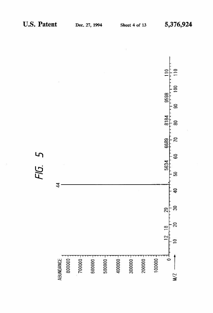
spectrometric result of a gas produced due to reduction in weight before ignition; FIG. 5 is a characteristic diagram showing the mass
spectrometric result of a gas produced in the combus tion process after ignition;

5,376,924 3
FIG. 6 is a ?owchart showing the processing of the embodiment shown in FIG. 1; FIG. 7 is a diagram showing a con?guration of a
second embodiment of the invention; FIG. 8 is a diagram showing a con?guration of a third
embodiment of the invention; FIG. 9 is a ?owchart showing the processing of a ?re
sensor 13 shown in FIG. 8; FIG. 10 is a diagram showing a con?guration of a
fourth embodiment of the invention; FIG. 11 is a diagram showing a spectral pattern
which is a reference pattern indicating a spectrum in a normal, non-?re environment; FIG. 12 is a diagram showing a spectral pattern
which is a reference pattern for judging hydrocarbon gas produced at a very early stage of a ?re before igni tion; FIG. 13 is a diagram showing a spectral pattern
which is a reference pattern showing the mass spectrum of gases including CO2 gas in addition to hydrocarbon gas produced by ignition; FIG. 14 is a diagram showing a basic three-variable
con?guration of another embodiment of the invention; FIG. 15 is a ?owchart showing the processing of a
?re sensor shown in FIG. 14; FIG. 16 is a diagram showing a basic two-variable
con?guration of another embodiment of the invention; FIG. 17 is a flowchart showing the processing of a
?re sensor shown in FIG. 16;
10
15
20
25
FIG. 18 is a diagram showing a basic con?guration of 30 another two-variable embodiment of the invention; FIG. 19 is a ?owchart showing the processing of a
?re sensor shown in FIG. 18; FIG. 20 is a diagram showing another basic two-vari
able con?guration embodiment of the invention; FIG. 21 is a ?owchart showing the processing of a
?re sensor shown in FIG. 20.
DESCRIPTION OF THE PREFERRED EMBODIMENTS
FIG. 1 is a block diagram showing a fundamental inventive concept of the present invention. In FIG. 1, reference numeral 1 designates a gas sensor, particularly one for sensing the presence of a hydrocarbon gas within the ambient atmosphere of a space that is the subject of evaluation or monitoring. An example of the sensor is an absorption wavelength detecting type sen sor for observing variations in light reception amount, which are caused by light absorption wavelength char acteristic of carbon-hydrogen (C-H) coupling of the hydrocarbon gas. Further, either a sensor for discrimi nating the analysis pattern of the mass spectrum of a hydrocarbon gas or a semiconductor gas sensor having sensitivity in response to an existence of the hydrocar bon gas may be employed as the gas sensor 1.
Reference numeral 2 designates a ?re judgement section which compares a gas density of the hydrocar bon gas detected by the gas sensor 1 with a predeter mined threshold levelv that is set for judging the occur rence of ?re. An output signal from the judgment sec tion is produced to actuate a ?re alarm when the gas density exceeds the threshold. FIG. 2 is a diagram showing a con?guration of a ?rst
embodiment of the invention. In FIG. 2, reference nu meral 11 designates a hydrocarbon gas sensor that de tects in?ammable hydrocarbon gas produced during the heating process that occurs before ignition. Reference. numeral 12 designates a C02 sensor serving as a com
35
45
50
55
65
4 bustion gas sensor which detects CO2 gas produced in the combustion process.
Reference numeral 13 designates a ?re alarm system that includes a prealarm judgment section 14, a prea larm output section 15, a ?re judgment section 16, a ?re alarm section 17, and an environmental condition alarm section 18. The prealarm judgment section 14 generates a prea
larm output upon detection of at least a predetermined amount of hydrocarbon gas by the hydrocarbon gas sensor 11. Prealarm judgment section 14 provides the prealarm judgment output to the prealarm output sec tion 15 and outputs a prealarm by turning an indication lamp on, by buzzing, etc. At the same time, the prealarm judgment section 14 sets a prealarm ?ag to “ON” and inputs the prealarm ?ag to the ?re judgment section 16. The ?re judgment section 16 judges a ?re when the
content of CO2 gas detected by the CO2 sensor has been increased drastically with the prealarm ?ag from the prealarm judgment section 14 being set to “ON”, and causes the ?re alarm section 17 to generate a judgment output so that a ?re alarm will be given. On the other hand, if a drastic increase in the content
of CO2 gas has been judged by the ?re judgment section 16 with the prealarm ?ag from the prealarm judgment section 14 being reset (to “OFF”), the environment condition alarm section 18 generates a judgment output to sound an alarm or turn on a lamp to indicate environ mental deterioration by judging that such an increase is brought about by a non-?re cause such as smoking a cigarette or the like because no hydrocarbon gas has been produced. The reason why hydrocarbon gas is produced prior
to a ?re, such production of hydrocarbon gas being a basis of the invention, will be described with reference to FIG. 3, which is a characteristic diagram showing measured data. FIG. 3 shows test data obtained when a piece of
polyethylene (p——CH2CH2) as a sample is heated. More speci?cally, FIG. 3 shows both a change in weight indicated by a weight curve 5 and thermal reaction of the sample indicated by a thermal reaction curve 6 when the piece of polyethylene as a sample is heated at a predetermined gradient from an ambient temperature to 500° C., as indicated by a temperature curve 4. Fur ther, mass spectrometry that is conducted by supplying the gas produced in the combustion tests shown in FIG. 3 to a mass spectrometer will show that carrier gases for the mass spectrometer are: He (80%) and O2 (20%).
In FIG. 3, when the piece of polyethylene as a sample is heated to about 120° C., an endothermic reaction 7 occurs by which the thermal reaction curve 6 drops. The endothermic reaction 7 takes place due to the piece of polyethylene as a sample changing from a solid to a liquid by melting. As the sample is further heated, the sample is ignited
at about 400° C., which coincides with a time tf. This in turn caused such a drastic decrease in weight due to combustion as indicated by a decrease from point B to point C in the weight curve 5 corresponding to the increase in temperature from 400° to 500° C. The ther mal reaction curve 6 peaks at the ignition time tf with an exothermic reaction 8. As determined in accordance with the present inven
tion, when the temperature of the sample is increased from 300° to 400° C. along curve 4 and the weight curve 5 proceeds to point B before ignition at the time tf, a decrease in weight of the sample, although slight, is
5,376,924 5
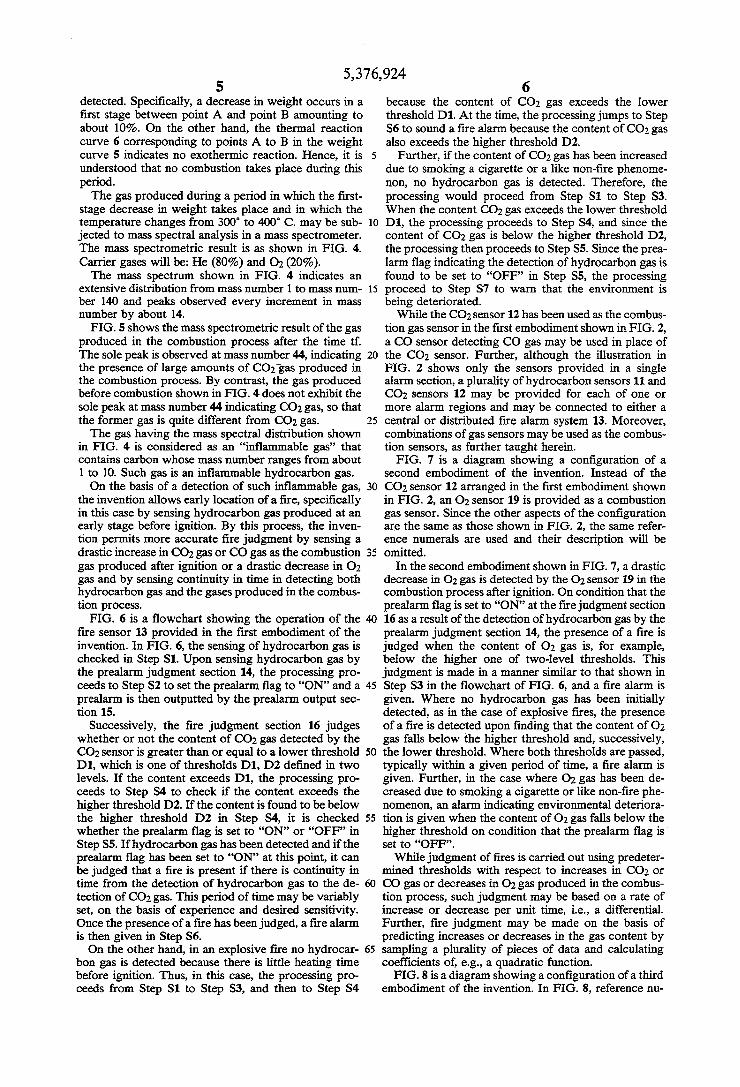
detected. Speci?cally, a decrease in weight occurs in a ?rst stage between point A and point B amounting to about 10%. On the other hand, the thermal reaction curve 6 corresponding to points A to B in the weight curve 5 indicates no exothermic reaction. Hence, it is understood that no combustion takes place during this period. The gas produced during a period in which the ?rst
stage decrease in weight takes place and in which the temperature changes from 300“ to 400° C. may be sub jected to mass spectral analysis in a mass spectrometer. The mass spectrometric result is as shown in FIG. 4. Carrier gases will be: He (80%) and O1 (20%). The mass spectrum shown in FIG. 4 indicates an
extensive distribution from mass number 1 to mass num ber 140 and peaks observed every increment in mass number by about 14. FIG. 5 shows the mass spectrometric result of the gas
produced in the combustion process after the time tf. The sole peak is observed at mass number 44, indicating the presence of large amounts of COg’gas produced in the combustion process. By contrast, the gas produced before combustion shown in FIG. 4 does not exhibit the sole peak at mass number 44 indicating CO2 gas, so that the former gas is quite different from C0; gas. The gas having the mass spectral distribution shown
in FIG. 4 is considered as an “in?ammable gas” that contains carbon whose mass number ranges from about 1 to 10. Such gas is an in?ammable hydrocarbon gas. On the basis of a detection of such inflammable gas,
the invention allows early location of a ?re, speci?cally in this case by sensing hydrocarbon gas produced at an early stage before ignition. By this process, the inven tion permits more accurate ?re judgment by sensing a drastic increase in CO2 gas or CO gas as the combustion gas produced after ignition or a drastic decrease in 02 gas and by sensing continuity in time in detecting both hydrocarbon gas and the gases produced in the combus tion process. FIG. 6 is a ?owchart showing the operation of the
?re sensor 13 provided in the ?rst embodiment of the invention. In FIG. 6, the sensing of hydrocarbon gas is checked in Step S1. Upon sensing hydrocarbon gas by the prealarm judgment section 14, the processing pro ceeds to Step S2 to set the prealarm ?ag to “ON” and a prealarm is then outputted by the prealarm output sec tion 15.
Successively, the ?re judgment section 16 judges whether or not the content of CO2 gas detected by the CO2 sensor is greater than or equal to a lower threshold D1, which is one of thresholds D1, D2 de?ned in two levels. If the content exceeds D1, the processing pro ceeds to Step S4 to check if the content exceeds the higher threshold D2. If the content is found to be below the higher threshold D2 in Step S4, it is checked whether the prealarm ?ag is set to “ON” or “OFF” in Step S5. If hydrocarbon gas has been detected and if the prealarm ?ag has been set to “ON” at this point, it can be judged that a ?re is present if there is continuity in time from the detection of hydrocarbon gas to the de tection of CO2 gas. This period of time may be variably set, on the basis of experience and desired sensitivity. Once the presence of a ?re has been judged, a ?re alarm is then given in Step S6. On the other hand, in an explosive fire no hydrocar
bon gas is detected because there is little heating time before ignition. Thus, in this case, the processing pro ceeds from Step S1 to Step S3, and then to Step S4
10
20
25
30
35
40
45
50
55
65
6 because the content of CO2 gas exceeds the lower threshold D1. At the time, the processing jumps to Step S6 to sound a ?re alarm because the content of CO2 gas also exceeds the higher threshold D2.
Further, if the content of CO2 gas has been increased due to smoking a cigarette or a like non-?re phenome non, no hydrocarbon gas is detected. Therefore, the processing would proceed from Step S1 to Step S3. When the content CO2 gas exceeds the lower threshold D1, the processing proceeds to Step S4, and since the content of CO2 gas is below the higher threshold D2, the processing then proceeds to Step S5. Since the prea larm ?ag indicating the detection of hydrocarbon gas is found to be set to “OFF” in Step S5, the processing proceed to Step S7 to warn that the environment is being deteriorated. While the CO2 sensor 12 has been used as the combus
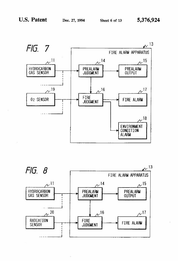
tion gas sensor in the ?rst embodiment shown in FIG. 2, a CO sensor detecting CO gas may be used in place of the CO2 sensor. Further, although the illustration in FIG. 2 shows only the sensors provided in a single alarm section, a plurality of hydrocarbon sensors 11 and CO2 sensors 12 may be provided for each of one or more alarm regions and may be connected to either a central or distributed ?re alarm system 13. Moreover, combinations of gas sensors may be used as the combus~ tion sensors, as further taught herein. FIG. 7 is a diagram showing a con?guration of a
second embodiment of the invention. Instead of the CO2 sensor 12 arranged in the ?rst embodiment shown in FIG. 2, an 0; sensor 19 is provided as a combustion gas sensor. Since the other aspects of the con?guration are the same as those shown in FIG. 2, the same refer ence numerals are used and their description will be omitted.
In the second embodiment shown in FIG. 7, a drastic decrease in 02 gas is detected by the 0; sensor 19 in the combustion process after ignition. On condition that the prealarm ?ag is set to “ON” at the ?re judgment section 16 as a result of the detection of hydrocarbon gas by the prealarm judgment section 14, the presence of a ?re is judged when the content of 02 gas is, for example, below the higher one of two-level thresholds. This judgment is made in a manner similar to that shown in Step S3 in the ?owchart of FIG. 6, and a ?re alarm is given. Where no hydrocarbon gas has been initially detected, as in the case of explosive ?res, the presence of a ?re is detected upon ?nding that the content of 02 gas falls below the higher threshold and, successively, the lower threshold. Where both thresholds are passed, typically within a given period of time, a ?re alarm is given. Further, in the case where 02 gas has been de creased due to smoking a cigarette or like non-?re phe nomenon, an alarm indicating environmental deteriora tion is given when the content of 02 gas falls below the higher threshold on condition that the prealarm ?ag is set to “OFF”. While judgment of ?res is carried out using predeter
mined thresholds with respect to increases in CO; or CO gas or decreases in 02 gas produced in the combus tion process, such judgment may be based on a rate of increase or decrease per unit time, i.e., a differential. Further, ?re judgment may be made on the basis of predicting increases or decreases in the gas content by sampling a plurality of pieces of data and calculating coef?cients of, e.g., a quadratic function. FIG. 8 is a diagram showing a con?guration of a third
embodiment of the invention. In FIG. 8, reference nu

5,376,924 7
meral 20 designates a radiation sensor, such as pyroelec tric element having a detection sensitivity in the infra red region, and senses radiated heat by exothermic reac tion in the combustion process. The other blocks FIG. 8 which are similar in function to those of FIG. 2 bear the same reference numerals, respectively. The prealarm judgment section 14 outputs a prealarm
from the prealarm output section 15 while judging the sensing of hydrocarbon gas by the hydrocarbon gas sensor 11. The prealarm judgment section 14 also sets a prealarm ?ag to “ON” upon judgment of the sensing of hydrocarbon gas, the prealarm ?ag being delivered to the ?re judgment section 16. The ?re judgment section 16 judges the intensity of
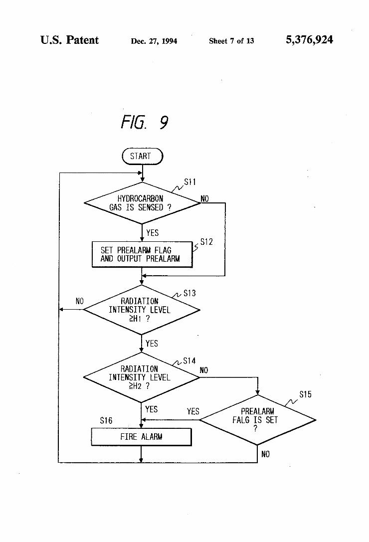
the radiated heat that has been detected by the radiation sensor 20. A ?re is judged upon detection of an increase in radiated heat subsequent to the detection of hydro carbon gas when the intensity of the radiated heat de~ tected by the radiation sensor 20 exceeds a threshold with the prealarm ?ag being set to “ON”. The ?re judgment section then causes the ?re alarm section 17 to sound a ?re alarm. FIG. 9 is a ?owchart showing the processing of the
?re alarm apparatus 13 shown in FIG. 8. In FIG. 9, it is checked if the hydrocarbon gas sensor 11 has sensed hydrocarbon gas in Step S11. When the sensing of hy drocarbon gas has been judged at the prealarm judg ment section 14, the processing proceeds to Step S12, where not only the prealarm ?ag to the ?re judgment section 16 is set to “ON”, but also a prealarm is output ted by the prealarm output section 15. Then, in Step S13, the ?re judgment section 16 com
pares the intensity of radiated heat detected by the radi ation sensor 20, i.e., a radiation intensity level with a lower threshold H1 out of thresholds de?ned in two levels. If the radiation intensity level is greater than or equal to the threshold H1, then the processing proceeds to Step S14, where the radiation intensity level is com pared with the higher threshold H2. If the radiation intensity level is smaller than the threshold H2, the processing proceeds to Step S15. If the prealarm flag is set to “ON” by the sensing of hydrocarbon gas, then the processing proceeds to Step S16 to sound a ?re alarm. On the other hand, explosive fires do not undergo the
process of producing hydrocarbon gas. With no sensing of hydrocarbon gas, the processing proceeds from Step S11 to Step S13. An explosive ?re exhibits a drastic increase in radiated heat, the increase exceeding not only the lower threshold H1 but also the higher thresh old H2. As a result, the processing jumps to Step S16 to directly give a ?re alarm.
Further, if it is found out that no hydrocarbon gas has been sensed in Step S11 and if the radiation intensity level has been found to exceed the lower threshold H1 in Step S13, which in turn causes the processing to proceed to Step S15, then no ?re alarm is given while judging that the increase in radiation intensity level is not derived from ?re but from, e.g., heat from an oil stove with the prealarm ?ag being set to “OFF”. The processing is then returned to Step S11.
In the embodiment shown in FIG. 8, it is designed to give a prealarm when hydrocarbon gas has been sensed by the hydrocarbon gas sensor 11 with providing the prealarm judgment section 14 and the prealarm output section 15. It may, however, be so arranged that a ?re is judged when, within a predetermined time, a hydrocar bon gas has been ?rst sensed and the intensity of radi
l0
15
25
40
45
50
55
60
65
8 ated heat exceeding predetermined thresholds is then sensed, without giving a prealarm.
Further, while fire judgment is made by comparing the intensity of the radiated heat detected by the radia tion sensor 20 with the thresholds, ?re judgment may be made based on an increment in radiated heat per unit time (a differential value), or on the prediction of a change in radiated heat by calculating coef?cients of a quadratic function while sampling a plurality of intensi ties of the radiated heat.
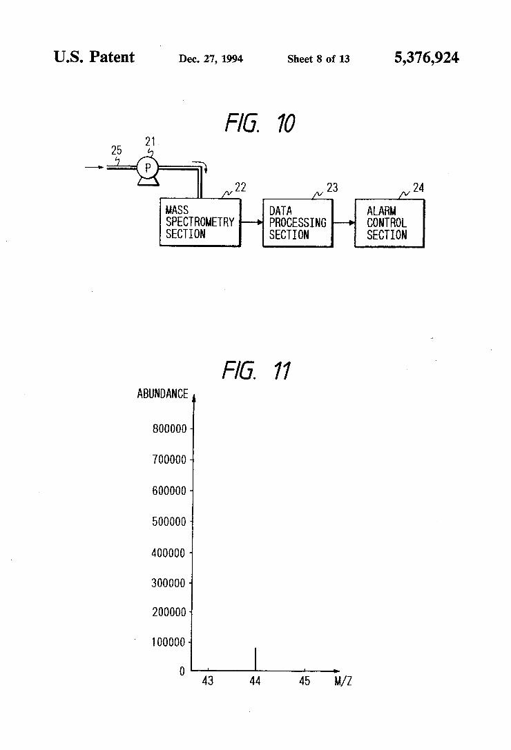
Still further, since the hydrocarbon gas is produced at a suf?ciently high temperature before ignition, a ?re may be located early by giving a prealarm or a ?re alarm when hydrocarbon gas has been sensed even before ignition and when the intensity of the radiated heat exceeding a predetermined threshold has been sensed. FIG. 10 is a diagram showing a con?guration of a
fourth embodiment of the invention. In FIG. 10, refer ence numeral 22 designates a mass spectrometry sec tion, which receives a gas to be subjected to mass spec trometry by a sampling pump 21 while using a piping 25 disposed in a monitoring area. This mass spectrometry section 22 is designed to obtain the mass spectrometric result in a narrow range including mass numbers 43, 44, and 45. That is, the mass spectrometry section 22 has the
same structure as an ordinary mass spectrometer capa ble of obtaining mass spectra covering a wide range of mass numbers. Since the mass numbers to be detected are limited to 43, 44, and 45, the sensing distances at the time of sensing with electrodes can be made as short as those corresponding to the mass numbers 43, 44, and 45 by sputtering ionized gas molecules. As a result, the structure of the mass spectrometry section 22 can me made extremely simple compared with ordinary mass spectrometers. The mass spectral data in the narrow range of mass
numbers 43, 44, and 45 obtained by the mass spectrome try section 22 are supplied to a data processing section 23. The data processing section 23 stores spectral pat terns, A spectral pattern shown in FIG. 11 is a reference pattern indicating a spectrum in a normal, non-?re envi ronment. A spectral pattern shown in FIG. 12 is a refer ence pattern for judging hydrocarbon gas produced at a very early stage of a ?re before ignition. A spectral pattern shown in FIG. 13 is a reference pattern showing the mass spectrum of gases including CO2 gas in addi tion to hydrocarbon gas produced by ignition.
Thus, the data processing section 23 executes pattern matching between a mass spectrum actually obtained by the mass spectrometry section 22 and the reference spectral patterns shown in FIGS. 11, 12, and 13, and judges a ?re when the spectral pattern including the CO2 gas shown in FIG. 13 is obtained after the spectral pattern of hydrocarbon gas shown in FIG. 12 has been obtained. Once the ?re has been judged, the data pro cessing section 23 causes an alarm control section 24 to output an alarm and carry out necessary control. The technique for judging a tire by carrying out mass
spectrometry in such a narrow range covering mass numbers 43, 44, and 45 in the invention is based on the fact that hydrocarbon gas is produced in the course of heating before ignition, which is a new fact that the inventors have found through tests on combustion in ?re involving mass spectrometry. A further embodiment of the invention concerns yet
another way that the presence of combustion may be

5,376,924 determined, for use alone or in combination with hydro carbon gas detection as described previously. In this regard, the following three theorems have been deter mined from the results of analyses made on gases pro duced in the combustion process. [Theorem 1] The production of CO and CO2 and the consumption of 02 take place simultaneous.
[Theorem 2] Neither CO nor CO2 is produced singly. [Theorem 3] The presence of 02 has little dependance on the fact that CO is produced in small amounts and CO2 is produced in large amounts during combustion. The following four types of ?re sensors may be based
on the theorems l to 3.
CONSTRUCTION l
A combination ?re sensor includes: a C02 sensor for detecting CO2 gas produced at a ?re; a CO sensor for detecting CO gas produced at the
?re; an 0; sensor for detecting 02 gas decreasing at the ?re; and
a comparison and calculation section for giving an alarm by judging the ?re when the content of the CO2 gas detected by the CO2 sensor and the con tent of the CO gas detected by the CO sensor have been increased and when the content of the 02 gas detected by the 0; sensor has been decreased.
CONSTRUCTION 2
A combination ?re sensor includes: a C02 sensor for detecting CO2 gas produced at a ?re; an 0; sensor for detecting 02 gas decreasing at the
?re; and a comparison and calculation section for giving an
alarm by judging the ?re when the content of the CO2 gas detected by the CO2 sensor has been in creased and when the content of the 02 gas de tected by the O2 sensor has been decreased.
CONSTRUCTION 3
A combination ?re sensor includes: a CO sensor for detecting CO gas produced at a ?re; an 0; sensor for detecting 02 gas decreasing at the
?re; and a comparison and calculation section for giving an alarm by judging the fire when the content of the CO gas detected by the CO sensor has been in creased and when the content of the 02 gas de tected by the O2 sensor has been decreased.
CONSTRUCTION 4
A combination ?re sensor includes: a C02 sensor for detecting CO2 gas produced at a ?re; a CO sensor for detecting CO gas produced at the
?re; and a comparison and calculation section for giving an alarm by judging the fire when the content of the CO2 gas detected by the CO2 sensor has been in creased and when the content of the CO gas de tected by the CO sensor has been increased.
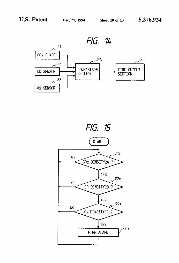
As previously noted, the four constructions may be used alone and have signi?cant advantages over the conventional designs or may be used in connection with a hydrocarbon detector for even further accuracy. The arrangement and operation of these basic constructions will now be described. FIG. 14 is a diagram showing a con?guration of
another embodiment of the invention. In FIG. 14, a C02 sensor 31, a CO sensor 32, and an O2 sensor 33 are
10 provided so that the embodiment can detect all combus tion gases CO2, CO, and 02 which are objects to be detected, respectively. The output of each of the CO2 sensor 31, the CO sensor 32, and the 0; sensor 33 is fed to a comparison section 34A. The comparison section 34A performs processing shown in the ?owchart of
. FIG. 15, and outputs an alarm while applying a ?re
15
20
25
35
45
50
55
65
output signal to a ?re output section 35 when a ?re has been judged. The processing at the comparison section 34A shown
in FIG. 15 is as follows. In Step Sla, it is judged whether or not the CO2 content detected by the CO2 sensor 31 is greater than or equal to a predetermined threshold A. If the CO2 content is greater than or equal to the threshold A, the processing is proceeded to Step S2a, where it is judged whether or not the CO content detected by the CO sensor 32 is greater than or equal to a predetermined threshold B. If the CO content is greater than or equal to the threshold B, then the pro cessing is proceeded to Step S3a, where it is judged whether or not the 02 content detected by the 0; sensor 33 is smaller than or equal to a predetermined threshold C. If the 02 content is smaller than or equal to the threshold C, then the processing is proceeded to Step 54a, where a ?re alarm is given. The judgment processing of FIG. 15 performed by
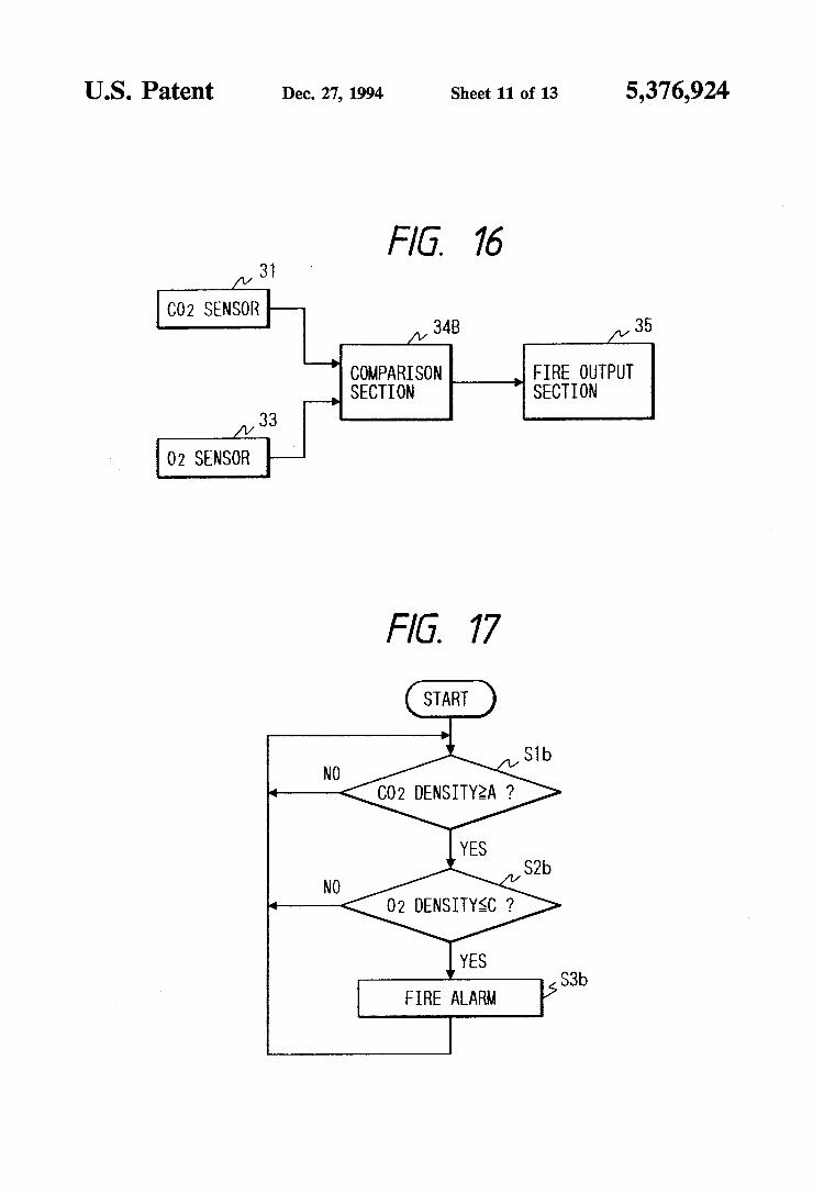
the comparison section 34A based on the results of detection of CO2, CO, and O2 is an application of all the above-mentioned theorems to ?re judgment. FIG. 16 is a diagram showing a con?guration of
another embodiment of the invention. This embodiment is characterized as performing processing shown in the ?owchart of FIG. 17 by the comparison section 34b based on two detection outputs of the CO2 sensor 31 and the 0; sensor 33. More speci?cally, as shown in the ?owchart of FIG. 17, it is judged that the CO2 content is greater than or equal to the threshold A in Step Slb. If the CO2 content is greater than or equal to the thresh old A, then the processing is proceeded to Step S2b. In Step S2b, it is judged whether or not the 02 content is smaller than or equal to the threshold C. If the 02 con tent is smaller than or equal to the threshold C, the processing proceeds to Step S3b, where a ?re alarm is given. FIG. 18 is a diagram showing a con?guration of a
further embodiment. This embodiment is characterized as judging a ?re by performing processing shown in the ?owchart of FIG. 19 by the comparison section 24C while using two detection outputs of the CO sensor 32 and the 0; sensor 33. More speci?cally, as shown in the ?owchart of FIG. 19, it is judged whether or not the CO content is greater than or equal to the threshold B in Step S10. If the CO content is greater than or equal to the threshold B, then the processing is proceeded to Step S2c. In Step S2c, it is judged whether or not the 02 content is smaller than or equal to the threshold C. If the 02 content is smaller than or equal to the threshold C, the processing proceeds to Step S3c, where a ?re alarm is given. FIG. 20 is a diagram showing a con?guration of yet
another embodiment. This embodiment is characterized as judging a ?re by performing processing shown in the ?owchart of FIG. 21 by the comparison section 34D while using two detection outputs of the CO2 sensor 31 and the CO sensor 32. More speci?cally, as shown in the ?owchart of FIG. 21, it is judged that the CO2 content is greater than or equal to the threshold A in Step Sld. If the CO2 content is greater than or equal to

5,376,924 11
the threshold A, then the processing proceeds to Step S2d. In Step S2d, it is judged whether or not the CO content is greater than or equal to the threshold B. If the CO content is greater than the threshold B, the process ing is proceeded to Step S3d, where a ?re alarm is given. While ?re judgment is carried out by comparing the
contents of CO2, CO, and 02 with the predetermine thresholds A, B, C, respectively, ?re judgment may be made based on a rate of increase or decrease per unit time, i.e., a differential. Further, ?re judgment may be made by ?nding a plurality of pieces of data while sam pling the content of each gas at a predetermined cycle, determining coef?cients of, e.g., a quadratic function for prediction, and predicting a remaining time before reaching dangerous gas density level. As described above, the invention allows a ?re to be
detected and a prealarm to be given at a very early stage of the ?re before ignition, which is based on detection of hydrocarbon gas, through which early discovery of the phenomenon of ?re is achieved, neither the CO2 gas sensor, the CO gas sensor, nor the 02 gas sensor could sense unless the combustion process starts. Also, by combining the detection of hydrocarbon gas with the detection of CO2 gas, a change only in the content of CO2 gas due to smoking a cigarette or a like non-?re phenomenon can be processed as environmental deteri oration other than ?res. As described above, the invention can judge a ?re
surely compared with ?re sensor employing a single gas sensor. Also, a ?re can be judged based on simple pro cessing without recourse to complicated signal process ing or information processing. That is, by de?ning the tendencies to produce CO2 gas, CO gas, and 02 gas at a ?re as three theorems based on the research concerning combustion, a comparison is made on the gases to see that the produced gases match these theorems.
Further, since gases are produced quickly than heat or smoke, ?res can be located quickly. What is claimed is: i
1. A ?re sensing method comprising the steps of: monitoring gas content in a de?ned area; storing a reference spectral pattern representing a ?re
condition based upon combustible gases; detecting hydrocarbon gas which is produced at a
very early state of ?re before ignition; outputting a pre-alarm signal upon detection of said hydrocarbon gas indicating a potential ?re condi tion;
performing spectral analysis of said gas content an increase in level of combustible gases;
comparing a detected spectral pattern with spectral pattern to determine whether a ?re condition ex
iStS; generating a signal to indicate the detection of ?re
only when both said hydrocarbon gas is detected and said detected spectral pattern corresponds to said reference pattern.
2. A ?re sensing method comprising the steps of: detecting hydrocarbon gas which is produced at a
very early state of ?re before ignition; outputting a pre-alarm signal upon detection of said hydrocarbon gas indicating a possible ?re condi tion;
detecting a second gas which is produced after ?re ignition;
15
20
25
30
35
45
65
12 detecting one of a signi?cant increase and signi?cant
decrease in said second gas after detection of said hydrocarbon indicating a ?re condition; and
outputting a signal indicating detection of a ?re only when both said hydrocarbon gas is detected and said one of an increase and decrease is detected in said second gas.
3. The method of claim 2, wherein said ?rst gas is a hydrocarbon gas and said second gas is at least one of CO2, CO and O2.
4. The method of claim 3, wherein said second gas comprises 02 and said second gas detecting step com prises detecting a signi?cant decrease in 02 gas.
5. The method of claim 3, wherein said second gas comprises detecting a signi?cant increase in at least one of CO and CO2 gas.
6. A ?re sensing method comprising the steps of: detecting hydrocarbon gas which is produced at a very early state of ?re before ignition;
detecting at least one of radiated heat and tempera ture; and
generating a signal to indicate the detection of ?re only when said hydrocarbon gas has been detected and when said at least one of said radiated heat and temperature is detected after detection of said hy drocarbon gas.
7. The method of claim 6, wherein said step of detect ing said at least one of radiated heat and temperature comprises sensing when one of said radiated heat and said temperature exceeds respective predetermined val ues.
8. The method of claim 6, wherein said step of detect ing at least one of radiated heat and temperature com prises sensing when an incremental value per unit of time of one of said radiated heat temperature exceeds respective predetermined values.
9. A ?re sensing method comprising the steps of: detecting hydrocarbon gas at a very early state of a
?re before ignition; detecting a second gas which is produced after ?re
ignition; detecting one of an increase and decrease in amount
of said second gas; and generating a signal to indicate detection of a ?re only when both said hydrocarbon gas is detected and said one of an increase and decrease in said second gas is detected.
10. A ?re sensing method as set forth in claim 9, wherein said detecting step for detecting said one of an increase and decrease in said second gas is based on a rate of change of a said amount per unit of time.
11. A ?re sensing method comprising the step of: determining whether hydrocarbon gas is present in a
monitored region; detecting at least a ?rst gas and a second gas produc
ing during a combustion process; detecting an increase in both said ?rst gas and said
second gas; and generating an alarm when an increase in both said
?rst gas and said second gas is detected. 12. A ?re sensor comprising: a hydrocarbon gas sensor for detecting hydrocarbon
gas produced before ignition; a combustion gas sensor for detecting gases produced
during a combustion process caused by said ?re; a ?re judgment section for detecting the occurrence
of a ?re based upon whether said hydrogen gas is
