w40/60-m eco installation and remeh… · electric rating fuse rating isolation class...
TRANSCRIPT

remehaW40/60-m ECO
Installation and maintenance instructions
High-efficiencycondensing boilerfor free standing (framemounted) or wallmounted installation
Suitable for room sealedfanned flue or open flue fan assisted operation

2
remeha W40/60-m ECO
CONTENTS
Preface 4
1. General description of the boiler 4
2. Construction 4
3. Technical data and dimensions 53.1 Dimensions 53.2 Technical data 63.3 Delivery package 6
4. Efficiency information 74.1 Annual efficiency 74.2 Heat to water efficiency 7
5. Installation applications 75.1 General 7
5.1.1 Installation of single boilers 75.1.2 Installation of multiple boilers 8
6. Boiler layout 96.1 Equipment diagram 96.2 Operating principle 106.3 Control panel 106.4 Control system 11
6.4.1 General 116.4.2 Operating mode 126.4.3 Setting mode (with dot) 136.4.4 Read-out mode (with blinking dot) 146.4.5 Forced 'HIGH' mode 146.4.6 Forced 'LOW' mode 146.4.7 Speed mode (half digits) 146.4.8 Failure mode (blinking 'code' display)156.4.9 Service code 156.4.10 User settings 16
7. Installation instructions 177.1 General 177.2 Location 177.3 Dimensions of wall mounting bracket 177.4 Ventilation requirements 187.5 Flue gas discharge and air supply 19
7.5.1 General 197.5.2 Single boiler,
non room sealed applications 207.5.3 Single boiler,
room sealed applications 217.5.4 Cascade configurations 21
7.6 Installation details 227.6.1 Condensate discharge 227.6.2 Cold feed and expansion tank
height for open vented systems 227.6.3 Water treatment 227.6.4 Safety valve 237.6.5 Circulation pump 23
7.7 D.H.W. application 237.7.1 D.H.W. control 237.7.2 Schematic sketch of connections 24

3
8. Electrical installation 258.1 General 258.2 Electrical supply 258.3 Connection to the control system 25
8.3.1 Modulating control 258.3.2 Room thermostat 24V 268.3.3 Room thermostat in combination
with an outdoor temperature sensor 268.3.4 Two-stage external weather
compensator 268.3.5 D.H.W. control 268.3.6 Frost protection 278.3.7 Signals 27
8.4 Water temperature control 288.5 Low-water protection 288.6 High limit temperature protection 288.7 Differential air pressure switch (LD2) 288.8 Control box 288.9 Fuse specification 288.10 Electrical wiring diagram 29
9. Installation instructions for the gas Installer 309.1 Gas connection 309.2 Gas pressures 309.3 Gas/air ratio control 30
10. Commissioning 3110.1 Initial lighting 3110.2 Shut-down 3210.3 Settings 33
10.3.1 General 3310.3.2 Setting the required flow
temperature 3310.3.3 Setting the required flow
temperature when using an outdoor sensor 33
10.3.4 Changing the cut-in temperature differential 33
10.3.5 Setting the pump control 3310.3.6 Setting the burner control 3310.3.7 Setting D.H.W. temperature 3410.3.8 Switching D.H.W. operation
on and off 3410.3.9 Changing D.H.W. operating cut-in
differential (service level) 3410.3.10 Changing maximum flow
temperature during D.H.W.operation 34
10.3.11 Changing three-way valve/boiler pump setting 34
11. Fault-finding 3511.1 General 3511.2 Faults in appliances in combination with
the rematic® weather-compensated boiler control 35
11.3 Faults in appliances without a modulatingrematic® weather-compensated boiler control 35
11.4 Fault codes 35
12. Inspection and servicing instructions 3712.1 General 3712.2 Inspection 3712.3 Maintenance 3812.4 Draining and filling 3912.5 Venting 39
4
remeha W40/60-m ECO
If you have any questions, or if you need more infor-mation about specific subjects relating to this boiler,please do not hesitate to contact us.The data published in these technical instructions isbased on the latest information and is subject to revi-sions.We reserve the right to modify the design and/or confi-guration of our products at any moment without beingobliged to adjust earlier supplies accordingly.
PREFACE
These technical instructions contain useful and importantinformation for the correct operation and maintenance ofthe remeha central heating boiler, models W40/60-mECO.Furthermore, important instructions are given to ensuresafe and trouble free boiler operation.Read these instructions carefully before putting the boi-ler into operation, familiarize yourself with its operationand control and strictly observe the instructions given.
The remeha W40/60-m ECO can be easily programmedand controlled using the built in microprocessor. Actualand set values can be checked from the read-out display.Gas and water connections are sited at the bottom ofthe boiler whilst combustion air inlet and flue dischargeconnections are located at the top of the casing.For multiple boiler applications refer to the TechnicalInformation "Multiple units".
The boiler meets the requirements of the EC regulationsof the directives:- 90-m/396/EEC Gas appliances directive- 92/42/EEC Efficiency directive- 73/23/EEC Electrical low voltage directive- 89/392/EEC Machinery directive- 89/336/EEC E.M.C. directiveW40-m ECO - PIN-number: 63/AO/6520.W60-m ECO - PIN-number: 63/AP/6520.For further advice or information contact Broag Ltd.
1. GENERAL DESCRIPTION OF THE BOILER
The remeha W40/60-m ECO is a condensing boilerwhich may be installed free standing on a frame or wallmounted on a bracket. The boiler is suitable for roomsealed fanned flue or open flue fan assisted applications.The boiler is designed for central heating and indirecthot water supply at working pressures not exceeding 3bar. It should be installed on a pumped water circulationsystem and is suitable for both open and unvented sys-tem operation.The remeha W40/60-m ECO is fitted with a top mountedpremix gas burner firing downwards into an aluminiumheat exchanger. The application of the premix burner,with its carefully controlled gas/air ratio, water heatingefficiencies of 110.4% (NCV) are obtained in the con-densing mode with very low CO and NOx emissions.A condensate collector and a siphon for the condensatedrain is fitted at the bottom of the boiler.Quick connect latches on the air box cover make theunit easy to service and maintain.
2. CONSTRUCTION
A DC fan has been mounted on the combustion airsupply side, which guarantees the supply of the correctquantity of combustion air. Gas injection takes place in aspecial mixing section at the inlet of the fan.As a result, the optimum mixture of gas and air isachieved in the fan. A pre-mix burner, placed in the topof the appliance, guarantees optimum combustion.The remeha W40/60-m ECO heat exchanger is manu-factured in aluminium, and equipped with conductingpanels for optimum heat transfer.At the bottom of the appliance, a condensate collectortray and a siphon are responsible for dischargingcondensed water.
The closed air box increases safety, and facilitatesinstallation in practically any room.Through the use of microprocessor technology, theremeha W40/60-m ECO is simple to set and control.Display windows make it possible to check the currentand target settings.The gas and water connections are clearly mounted onthe underside of the appliance. The combustion airsupply and flue gas discharge are mounted on the topof the boiler (100 mm I/D socket).By using quick connect latches on the air box cover (noscrews), the appliance is also easy to service andmaintain.
5
3. TECHNICAL DATA AND DIMENSIONS
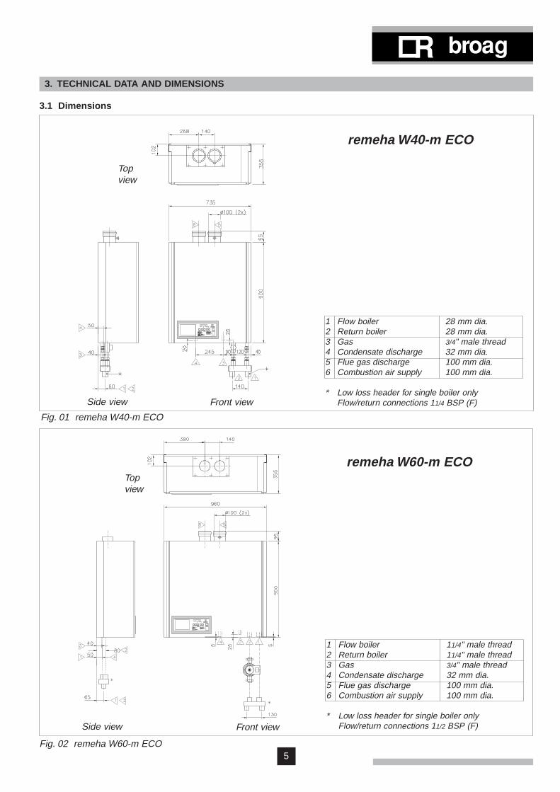
3.1 Dimensions
Topview
remeha W40-m ECO
Side view Front view
Fig. 01 remeha W40-m ECO
remeha W60-m ECO
1 Flow boiler 28 mm dia.2 Return boiler 28 mm dia.3 Gas 3/4" male thread4 Condensate discharge 32 mm dia.5 Flue gas discharge 100 mm dia.6 Combustion air supply 100 mm dia.
* Low loss header for single boiler onlyFlow/return connections 11/4 BSP (F)
Fig. 02 remeha W60-m ECO
Front viewSide view
Topview
1 Flow boiler 11/4" male thread2 Return boiler 11/4" male thread3 Gas 3/4" male thread4 Condensate discharge 32 mm dia.5 Flue gas discharge 100 mm dia.6 Combustion air supply 100 mm dia.
* Low loss header for single boiler onlyFlow/return connections 11/2 BSP (F)

6
remeha W40/60-m ECO
modulatinghigh - low
on - off18.260.520.366.420.769.018.662.1
II 2H 3P
17 - 302.0 - 6.6
18100,8104
B23, C13, C33,C43, C53, C63
240/50 100
220100
20 - 900.336
900not applicable
75
3.2 Technical data
Boiler type
Load control: adjustable
Output (80/60˚C) - min.- max.
(40/30˚C) - min.- max.
Input (GCV) - min.- max
Input (NCV) - min.- max
Category Inlet pressure gasGasrate (natural gas)NOx emission
Residual fan dutyMass flue rate Appliance (flue) type
Main supplyElectric ratingFuse ratingIsolation classWatertemperature - max.
- control Operating pressure - min.
- max.Water contentsWaterresistance (∆T = 10˚C)Residual pump duty (∆T = 20˚C)Assembly weight
modulatinghigh - low
on - off12,441.014.044.314.147.012.742.3
II 2H 3P
17 - 301.3 - 4.5
51290,871
B23, C13, C33,C43, C53, C63
240/50 150
220100
20 - 900.335
40035067
kWkWkWkWkWkWkWkW
mbarm3/hmg/kWh ppmmbarkg/h
V/HzVAAIP°C°Cbarbarltrmbarmbarkg
remeha W40-m ECO
remeha W60-m ECO
3.3 Delivery package- circulation pump- low loss header- pressure gauge- filling and drain cock- air supply fan- electronic control and protection equipment: 24V- interface for rematic® weather-compensated boiler
control- temperature regulation: adjustable from 20 to 90°C- differential air pressure switch- low-water protection via temperature sensors- aluminium heat exchanger- red spray-coated sheet steel casing- pump switch
- frost protection- easy-to-read control panel with display- siphon trap- hanging bracket- automatic vent.
Accessories- conversion set for propane- connection set for calorifier- outdoor temperature sensor- modulating rematic® weather-compensated boiler
control- interface for modulating room control (Honeywell
Chronotherm Modulation).

7
4. EFFICIENCY INFORMATION
4.1 Annual efficiencya. 103.3% (NCV), 93.0% (GCV) at an average watertemperature of 45˚C (55/35˚C).
4.2 Heat to water efficiencya. Up to 99.0% (NCV), 89.1% (GCV) at an averagewater temperature of 76.5˚C.b. Up to 110.4% (NCV), 99.4% (GCV) at an averagewater temperature of 45˚C.
5. INSTALLATION APPLICATIONS
5.1 GeneralThe boiler may be used with a fully pumped sealed oropen vented central heating system and pumped heat-ing combined with pumped indirect domestic hot watersupply systems.The remeha W40/60-m ECO is not suitable for systemswhich include any gravity circulation, bathroom installa-tions or connection to unlined brick chimneys.
5.1.1 Installation of single boilersThe low noise level emission of 48 dBA measured at 1m from the boiler makes the remeha W40/60-m ECOideal for installation as a single boiler in large domesticdwellings and smaller commercial premises.The single boiler should be supplied with a header(available from Broag).
Fig. 03 Header dimensions remeha W40-m ECO
Fig. 04 Header dimensions remeha W60-m ECO
8
remeha W40/60-m ECO
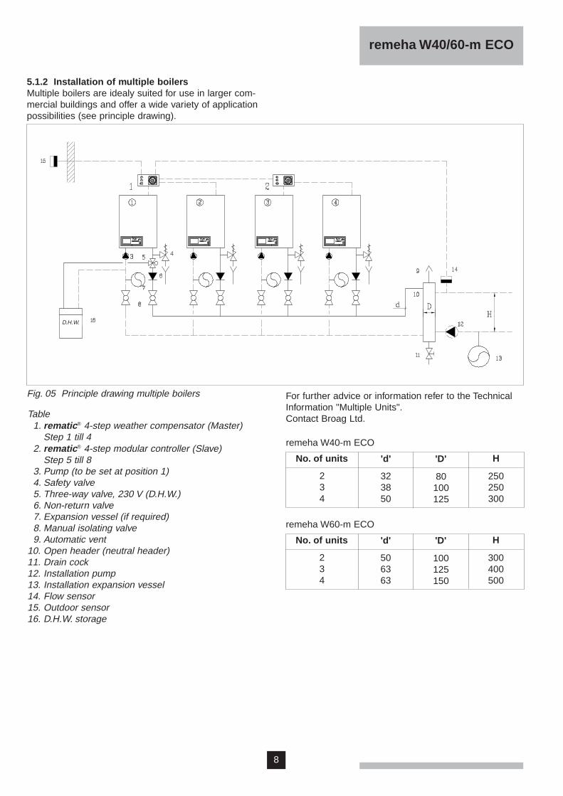
5.1.2 Installation of multiple boilersMultiple boilers are idealy suited for use in larger com-mercial buildings and offer a wide variety of applicationpossibilities (see principle drawing).
Fig. 05 Principle drawing multiple boilers For further advice or information refer to the TechnicalInformation "Multiple Units".Contact Broag Ltd.Table
1. rematic® 4-step weather compensator (Master)Step 1 till 4
2. rematic® 4-step modular controller (Slave)Step 5 till 8
3. Pump (to be set at position 1)4. Safety valve5. Three-way valve, 230 V (D.H.W.)6. Non-return valve7. Expansion vessel (if required)8. Manual isolating valve9. Automatic vent
10. Open header (neutral header)11. Drain cock12. Installation pump13. Installation expansion vessel14. Flow sensor15. Outdoor sensor16. D.H.W. storage
D.H.W.
No. of units
234
'D''d'
80100125
323850
remeha W40-m ECO
250250300
H
No. of units
234
'D''d'
100125150
506363
remeha W60-m ECO
300400500
H

9
1 2
3
4
11
12
16
18
21
23
25
26
31
33
30
2924
6
7 810
5
9
15
20
22
28
2732
35
17
19
34
14
Fig. 06 Boiler layout remeha W40-m ECO
6. BOILER LAYOUT
6.1 Equipment diagram
1. Air supply2. Flue gas discharge3. Measure point O2 /CO2
4. Air box5. Slide connector6. Differential air pressure switch7. Spring loaded damper8. Gas injector (behind fan)9. Fan
10. Automatic vent11. Burner12. Ignition/ionisation probe13. Sight glass14. Manual air vent15. Gas combi-block16. Heat exchanger17. Flow temperature sensor18. Inspection cover19. Return temperature sensor20. Condense collector21. Instrument panel22. Electrical connection strip (X15)23. Facility for incorporating a
rematic® weather compensatedboiler control
24. Condensate discharge25. Setting keys26. Read-out display and reset key27. Burner switch28. Interface for rematic® weather
compensated boiler control29. Gas connection30. Pump (only W40-m ECO)31. Pressure gauge32. Filling and drain cock33. Return connection34. Electrical connection pump and
three-way valve35. Flow connection
13

10
remeha W40/60-m ECO
6.2 Operating principleThe appliance is equipped with a closed air box. Via afan, air is drawn in. On the intake side of the fan, an inta-ke unit has been mounted where the gas is injected.Depending on the settings and the ambient tempera-tures measured by the temperature sensors, the fanspeed is regulated. The gas/air ratio control adjusts thequantity of gas to the quantity of air.The gas/air mixture is achieved in the fan, and thentransported to the burner.
Following combustion, the hot flue gases are conductedvia the aluminium heat exchanger. At the heat exchan-ger, the flue gases give off heat to the central heatingwater in the heat exchanger. The water vapour in the fluegases condenses against the finned pipes at the base.The heat released during this condensation process (theso-called latent or condensation heat) is also transferredto the central heating water.The condensed water thus formed is discharged via asiphon at the base of the heat exchanger.
6.3 Control panelThe remeha W40/60-m ECO is equipped with anadvanced control system comprising:a. an automatic microprocessor control systemb. a control panel with setting keys and read-out display.
Various values can be set and read, using the settingkeyboard and read-out displays.The two levels for setting and read-out are:- user level - free access- service level - access by service code.
The control panel accommodates the following compo-nents (fig. 07):
a. 'code'-displaydisplay of: - operating mode 1 digit
- setting mode 1. digit and dot- read-out mode 1. digit and blinking dot
in service level:- speed mode half digits- failure mode 1 blinking digit
b. temperature display ( )display of: - temperatures
- settings- malfunctions
c. 'reset'-key:- to reset after a malfunction
d. 'mode'-key:- key to select the required mode
e. 'step'-key:- key to select the required program within the
selected mode
f. 'store'-key:- key to save the settings
g. '▲'-key- to select a higher setting
h. '▼'-key:- to select a lower setting
i. burner switch:- to switch the boiler on/off.
c
g hfed
ab
Fig. 07 Control panel
i

11
Fig. 08 Flow diagram microprocessor
6.4 Control system
6.4.1 General
digit anddot
.
0-9H,L
digit
Temperature display'Code'-display
Press the 'step'-keyPress the 'mode'-key
1. Required flow temperature2. Pump setting3. D.H.W. settingA. Boiler control operation
On service level (C 12):
6. Fan speed at full load (hundreds)7. Fan speed at full load (units)8. Fan speed at part load (hundreds)9. Fan speed at part load (units)b. D.H.W. cut-in temperature differentialC. Max. fan speed D.H.W.d. Max. fan speed D.H.W.E. Not applicableF. Monitoring fan speed LD2 G. Forced part load after startH. Fan speed at start I. Max. flow temperature D.H.W.J. D.H.W. controlL. Reserven. Heating cut-in temperature differentialP. Security type
1. Flow temperature2. Return temperature 3. D.H.W. temperature 4. Outdoor temperature 5. Not applicable6. Flow temperature (setpoint)7. Room thermostat status and air pressure switch status8. Reserve9. Not applicable
.
Fan speed
blinkingdigit
1 Failure code2 Operating mode during failure3 Flow temperature during failure4 Return temperature during failure5 D.H.W. temperature during failure6 Outdoor temperature during failure
half digits
Flow temperature
or
Operatingmode (seepara. 6.4.2)
Settingmode (seepara. 6.4.3)
Read-outmode (seepara. 6.4.4)
Speedmode (seepara. 6.4.7)
Failuremode (seepara. 6.4.8)
digit andblinking dot
On service level (C 12):

12
remeha W40/60-m ECO
6.4.2 Operating modeDuring operation the 'code'-display shows the status(position in cycle) of the boiler, while the temperaturedisplays indicates the measured water temperature.
The digits in the 'code'-display have the following mean-ing:0 Standby; there is no heat demand from the heating or
hot water controls.1 Pre-purging; before start-up, the boiler is purged for
0,3 seconds. When the heat demand has been met,the fan continues to operate for another 10 seconds.
2 Ignition: ignition is activated for 2.4 seconds while thegas valve is opened.
3 Central heating mode; the boiler operates in the cen-tral heating mode.
4 D.H.W. operation: the boiler operates when the three-way valve serving the calorifier is actuated by ademand from the D.H.W. temperature sensor.
5 Waiting mode; the fan runs and the boiler waits untilthis has been proved or waits until the three-wayvalve has returned to the central heating position.
7 Continued pump operation in the central heatingmode: after heat demand is met, the pump continuesto operate for the time selected (if continuous pumpoperation has not been selected).
8 Continued pump operation in the D.H.W. mode; afterD.H.W. demand is met, the three-way valve will beenergized for another 5 minutes and the pump keepsrunning.
9 Control stop- flow temperature > 95˚C- flow temperature > setpoint +5˚C- return temperature > max. flow temp. -10˚C- rise in flow temperature exceeded.
HForced full load.L Forced part load.

13
6.4.3 Setting mode (with dot)Various settings can be changed as required in the set-ting mode.a. on user level- Select the setting mode by pressing the 'mode'-key
until 1. appears in the 'code' read-out display.- Now select the required code, using the 'step'-key.
Code Description Setting Preset
1. Required flow temperature - 2 0 - 9 0 ˚C 8 02. Pump setting - 0 0 pump operation 10 sec. 0 5
0 1 - 1 5 pump operation in minutes9 9 continuous pump operation
3. D.H.W. setting - 2 0 - 6 5 ˚C (with sensor) 6 5A. Boiler control operation - 1 X central heating modulating (or on/off) 1 1
( X = don't care) - 2 X central heating high/low - X 0 central heating off, D.H.W. off - X 1 central heating on, D.H.W. on- X 2 central heating on, D.H.W. off- X 3 central heating off, D.H.W. on
b. on service level for the heating contractor- Select the service code C 1 2 (see para. 6.4.9)- Select the setting mode by pressing the 'mode'-key
until 1. appears in the 'code'-read-out display.- Now select the required code, using the 'step'-key.
Code Description Setting Preset
6. Fan speed at full load - 1 0 - 6 0 hundreds 4 97. Fan speed at full load - 0 0 - 9 9 units 0 08. Fan speed at part load - 1 0 - 6 0 hundreds 3 09. Fan speed at part load - 0 0 - 9 9 units 0 0b. D.H.W. cut-in temp. differential - 0 1 - 0 5 ˚C 0 5
0 6 = 10 ˚C 0 7 = 15 ˚C0 8 = 20 ˚C
C. Max. fan speed D.H.W. - 1 0 - 6 0 hundreds 4 9d. Max. fan speed D.H.W. - 0 0 - 9 9 units 0 0E. ReserveF. Monitoring fan speed LD2 - May not be changed !!! 4 5
G. Forced part load after start - 0 0 - 1 5 minuten 0 0H. Fan speed at start - May not be changed !!! 3 5I. Max. flow temperature at D.H.W. - 7 0 - 9 0 ˚C 8 0J. D.H.W. control - 0 0 three-way valve 0 0
- 0 1 D.H.W. pump- 0 2 inverted three-way valve
n. Heating cut-in temp differential - 0 5 - 2 0 ˚C 1 0P. Security type - May not be changed !!! 1 4
14
remeha W40/60-m ECO
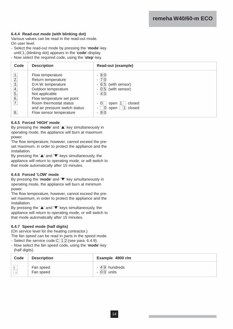
6.4.5 Forced 'HIGH' modeBy pressing the 'mode' and '▲' key simultaneously inoperating mode, the appliance will burn at maximumpower.The flow temperature, however, cannot exceed the pre-set maximum, in order to protect the appliance and theinstallation.By pressing the '▲' and '▼' keys simultaneously, theappliance will return to operating mode, or will switch tothat mode automatically after 15 minutes.
6.4.6 Forced 'LOW' modeBy pressing the 'mode' and '▼' key simultaneously inoperating mode, the appliance will burn at minimumpower.The flow temperature, however, cannot exceed the pre-set maximum, in order to protect the appliance and theinstallation.By pressing the '▲' and '▼' keys simultaneously, theappliance will return to operating mode, or will switch tothat mode automatically after 15 minutes.
6.4.7 Speed mode (half digits)(On service level for the heating contractor.)The fan speed can be read in parts in the speed mode.- Select the service code C 1 2 (see para. 6.4.9).- Now select the fan speed code, using the 'mode'-key
(half digits).
6.4.4 Read-out mode (with blinking dot)Various values can be read in the read-out mode.On user level.- Select the read-out mode by pressing the 'mode'-key
until 1. (blinking dot) appears in the 'code'-display.- Now select the required code, using the 'step'-key.
Code Description Read-out (example)
1. Flow temperature - 8 0 2. Return temperature - 7 0 3. D.H.W. temperature - 6 5 (with sensor)4. Outdoor temperature - 0 5 (with sensor)5. Not applicable - 4 06. Flow temperature set point7. Room thermostat status - 0 open 1 closed
and air pressure switch status - 0 open 1 closed8. Flow sensor temperature - 8 0
Code Description Example 4900 r/m
Fan speed - 4 9 hundredsFan speed - 0 0 units

15
6.4.9 Service codeOnly for the heating contractor.To avoid incorrect settings several operation levels haveprotection codes. For service purposes you can programcode C 1 2 .- Press the 'mode'- and 'step'-keys simultaneously and
the 'code'-display now shows C .- Holding both keys pressed, set the temperature dis-
play to 1 2 , using the '▲'- and '▼'-keys.
6.4.8 Failure mode (blinking 'code' display)Only for the heating contractor.Malfunctions of the boiler control occurring during opera-tion are shown on the read-out displays (see failuretable in chapter 11). The latest failure is stored in the mi-croprocessor memory and can be read at service level,code C 1 2 (see para. 6.4.9).- Press the 'mode'-key until the digit 1 (blinking)
appears in the 'code'-display.- Press the 'step'-key for the required code.
Code Description
1 3 7 Display of failure code (chapter 11)2 0 3 Operating mode during failure
(para. 6.4.2)3 5 3 Flow temperature during failure4 4 0 Return temperature during failure5 6 0 D.H.W. temperature during failure6 1 0 Outdoor temperature during failure
⇑ ⇑ ⇑ ⇑
- Keep both keys pressed and press the 'store'-key.The temperature display is blinking to acknowledgeyour access to the service setting.
- Press the 'store'-key to store the service code (thetemperature display will blink twice for acknowledge-ment).
- Release the 'mode' and 'step' keys.You are in the service mode and are able to change set-tings and to read out values.After using the service code you have to delete the ser-vice code by pressing the 'reset'-key once or after 10minutes when no further alterations have been made theservice code will delete automatically.
Example:The return temperature sensor has failed during centralheating operation at a flow temperature of 53°C, a returntemperature of 40°C, a D.H.W. temperature of 60°C andan outdoor temperature of 10°C.
⇑ ⇑ ⇑

16
remeha W40/60-m ECO
6.4.10 User settingsThe user can set the following parameters to therequired values.
1. Flow temperature (basic setting 80˚C).- Press the 'mode'-key until the digit 1. (with dot)
appears in the 'code'-display.- The set value 8 0 is shown in the temperature
display.- Now set the required flow temperature, using the
'▲'- and '▼'-keys.
Code Description
1. 7 0 Required flow temperature
- Press the 'store'-key to store the new value (value will blink twice).
- Press the 'mode'-key until the digit without dot appears in the 'code'-display.
2. Pump switching (basic setting: pump continues tooperate for 5 minutes)- Press the 'mode'-key until the digit 1. (with dot)
appears in the 'code'-display.- Press the 'step'-key until the digit 2. appears in the
'code'-display.- Set the required value, using the '▲'- and '▼'-keys.
3. D.H.W. setting (basic setting 65˚C). Only with sensor.- Press the 'mode'-key until the digit 1. (with dot)
appears in the 'code'-display.- Press the 'step'-key until the digit 3. appears in the
'code'-display.- Set the required value, using the '▲'- and '▼'-keys.
Code Description
2. 0 0 Pump continues to operate for 10 sec.2. X X Pump continues to operate for
1 - 15 min. (example: X X = 05)2. 9 9 Continuous pump operation
- Press the 'store'-key to store the new value (value will blink twice).
- Press the 'mode'-key until the digit without dot appears in the 'code'-display.
Code Description
3. 6 5 required temperature
- Press the 'store'-key to store the new value (value will blink twice).
- Press the 'reset'-key to return into the operating mode.
Operation is as follows:Imagine: the setpoint for D.H.W. temperature has beenpreset at 65°C, the D.H.W. cut-in temperature differen-tial at 5°C, and the maximum flow temperature duringD.H.W. operation at 80°C (factory settings).The appliance will modulate at the preset maximum flowtemperature during D.H.W. operation, and will shut downat a D.H.W. temperature of 70°C (preset value +5°C).The appliance will cut back in at a D.H.W. temperatureof 65°C (preset D.H.W. temperature +5°C - D.H.W. cut-in temperature differential).Both the D.H.W. cut-in differential and the maximum flowtemperature during D.H.W. operation can only be set viathe service menu (para. 10.3.9 and 10.3.10).

17
7. INSTALLATION INSTRUCTIONS
7.1 GeneralAll gas appliances must, by law, be installed by compe-tent persons (e.g. Corgi). Failure to install appliancescorrectly could lead to prosecution.It is in your own interest and that of safety to ensure thatthe law is complied with.The following instructions must be adhered to when theremeha W40/60-m ECO is installed:Gas Safety (Installation and Use) Regulations 1984 (asamended).Current I.E.E. Regulations for electrical installations Local building regulations.The Building Standards (Scotland) (Consolidation)Regulations, by-laws of the local water undertaking.Health and Safety Document No 635 'The Electricity atWork Regulations 1989'.The requirements of Guidance Note PM 5 issued by theHealth & Safety Executive 'Automatically controlledsteam and hot water boilers'.Depending on the type and size of installation i.e. largedomestic or commercial the requirements of the follow-ing publications should be complied with:Domestic: BS 5449, BS 5546, BS 6644,
BS 6891, CP 3006 and BG DM2.Commercial: BS 6644, BS 6700, BS 6880
Pts 1, 2 and 3, CP 342.2IM2, IM5, IM11, IM16 and IM22.
Manufacturers Instructions must NOT be taken as over-riding statutory obligations.
Important:The remeha W40/60-m ECO is a certified appliance andmust not be modified or installed in any way contrary tothese "Installation and Maintenance Instructions".
7.2 LocationThe remeha W40/60-m ECO may be mounted free stan-ding (on a frame supplied) or wall mounted (on a brack-et supplied). The floor should be level and strongenough to support the weight of the boilers full of water.The wall should be sound and flat and capable of sup-porting the weight of the boiler full of water.The following minimum clearances are required:Front: 450 mmSides: 50 mm Bottom: 250 mmTop: 400 mm.
7.3 Dimensions of wall mounting bracket
Fig. 09 Template for wall bracket remeha W40-m ECO
A = Drill hole
A = Drill hole
Fig. 10 Template for wall bracket remeha W60-m ECO

18
remeha W40/60-m ECO
Total input ratingof boilers
up to 2 MW
up to 2 MW
Position of airvents
High level
Low level
Minimum air vent area(direct from outside)
270 cm2 plus 25 cm2
per kW in excess of60 kW total input
540 cm2 plus 4.5 cm2
per kW in excess of60 kW total input
These recommendations are considered to be adequateunless plant is to be operated at, or near, maximum out-put during summer months when additional ventilationmay be required.
7.4 Ventilation requirementsa. Open flue installationsThe requirements for high and low level ventilation open-ings which MUST be provided are contained in detailwithin BS 6644.Openings must be permanent, communicate direct tooutside and be positioned so as to avoid blockage,flooding or high velocity draughts within the boilerhouse.The minimum free area of openings are shown in thetable:
b. Room sealed installationsBoilers require no air for combustion but air may berequired to ventilate the boiler house and remove anyexcess heat generated by auxiliary equipment. BS 6644requires that boiler house temperatures shall notexceed:- at floor level (or 100 mm above floor level) 25˚C- at mid level (1.5 m above floor level) 30˚C- at ceiling level (or 100 mm below ceiling level) 40˚C.

19
7.5 Flue gas discharge and air supply
7.5.1 GeneralThe remeha W40/60-m ECO is suitable for room sealedfanned flue or open flue fan assisted operation.Separate flue discharge and combustion air inlet con-nections are located on top of the appliance.These are sealed with dust caps which MUST be remo-ved just before the flue discharge and any air supplyducts are fitted.The boiler, in either single or multiple configurations issuitable for operation with a wide variety of flue systems(see section 7.5.2). Any horizontal runs of flue ductingMUST slope back towards the boiler. Horizontal runs ofair ducting MUST slope towards the outside supplyopening. The flue duct termination must be located suchthat when exposed to wind it will remain under suctionwhen the appliance is out of operation.The flue should be constructed from single walled alu-minium or stainless steel (316) and any air supply ductsfrom either single walled aluminium, stainless steel orplastic. All seams and joints in the flue shall be air andwatertight. When room sealed applications are adoptedall seams and joints in the air supply ductwork must beairtight.
Purpose designed flue and air systems for all applica-tions are available from: - Rite-Vent Ltd
Crowther Industrial EstateWashington NE 38 OABTel.no.: 0191 - 4161150Fax.no.: 0191 - 4151263
or - Selkirk Manufacturing LtdBassett HouseHigh StreetBanstead SM7 2LZTel.no.: 01737 - 353388 Fax.no.: 01737 - 362501.
Fig. 11 Flue gas discharge and air supply

20
remeha W40/60-m ECO
7.5.2 Single boiler, non room sealed applicationsConstruction of flue gas discharge duct1 = flue gas discharge duct without bends2 = flue gas discharge duct with two 45˚ bends3 = flue gas discharge duct with two 90˚ bends4 = flue gas discharge duct with T inlet and 90˚ bend, or
flue gas discharge duct with two 45˚ bends
H
Fig. 12 Examples of flue gas discharge duct, singleboiler, non room sealed applications.
Lengths over 40 metres: consult Broag Ltd.NB: deduct 2 metres of piping length for each 90˚ bend.
1 2 3 41 2 3 4
2640
2340
1340
1040
2440
2140
1140
840
80100
Outlet without Terminal'free outlet'
Outlet with Terminal
Min. and max. allowable lengths of the flue gas discharge piping 'H' in mD (in mm)
Ø
1 2 3 41 2 3 4
936
734
-22
-18
734
532
-20
-16
80100
Outlet without Terminal'free outlet'
Outlet with Terminal
Min. and max. allowable lengths of the flue gas discharge piping 'H' in mD (in mm)
Ø
remeha W40-m ECO
remeha W60-m ECO
Lengths over 40 metres: consult Broag Ltd.NB: deduct 2 metres of piping length for each 90˚ bend.

21
7.5.3 Single boiler, room sealed applications
H
Fig. 13 Examples of flue gas discharge duct, singleboiler, room sealed applications.
-20
80100
Min. and max. allowable total lengths of the flue gas discharge and air supply piping 'H' in m together
7 +)6 +)
720
5 +)
230
D (in mm)
Ø
-18
100110 *
Min. and max. allowable total lengths of the flue gas discharge and air supply piping 'H' in m
7 +)6 +)
1620
5 +)
D (in mm)
Ø
remeha W40-m ECO
+) Lengths over 20 metres: consult Broag Ltd.NB: deduct 2 metres of piping length for each 90˚ bend.
remeha W60-m ECO
620
+) Lengths over 20 metres: consult Broag Ltd.NB: deduct 2 metres of piping length for each 90˚ bend.* = Concentric outlet Ø 100 mm.
7.5.4 Cascade configurationsFor flue gas-side and air-side connections for multipleboilers in cascade configuration, refer to our specificdocumentation on that subject.
@@@@@@@@@@@@@@f@@@@@@@@@@@@@@f@@hf@@hf@@hf@@hf@@@@@?h@@@@@?h@@@@@?h@@@@@?h@@@@@?h@@@@@?h@@@@@?h@@@@@?h@@hf@@hf@@hf@@hf@@hf@@hf@@hf@@hf@@hf@@hf@@hf@@hf@@hf@@hf@@hf@@hf@@hf@@hf@@hf@@hf@@hf@@hf@@hf@@hf@@hf@@hf@@hf@@hf@@hf@@hf@@hf@@hf@@hf@@hf@@hf@@hf@@hf@@hf@@hf@@hf@@hf@@hf@@hf@@hf@@hf@@hf@@hf@@hf@@hf@@hf@@hf@@hf@@hf@@hf@@hf@@hf@@hf@@hf@@hf@@hf@@hf@@hf@@hf@@hf@@hf@@hf@@hf@@hf@@hf@@hf@@hf@@hf@@hf@@hf@@hf@@hf@@hf@@hf@@hf@@hf@@hf@@hf@@hf@@hf@@hf@@hf@@hf@@hf@@hf@@hf@@hf@@hf@@hf@@hf@@hf@@hf@@hf@@hf@@hf@@hf@@hf@@hf@@hf@@hf@@hf@@hf@@hf@@hf@@hf@@hf@@hf@@hf@@hf@@hf@@hf@@hf@@hf
@@@@@@hf@@@@@@hf@@@@@@hf@@@@@@hf@@@@@@hf@@hf@@hf@@@@hf@@@@hf@@@@hf@@@@@@hf@@@@@@hf@@@@hf@@@@hf@@@@hf@@hf@@hf@@hf@@hf@@hf@@hf@@hf@@hf@@hf@@hf@@hf@@hf@@hf@@hf@@hf@@hf@@hf@@hf@@hf@@hf@@hf@@hf@@hf@@hf@@hf@@hf@@hf@@hf@@hf@@hf@@hf@@hf@@hf@@hf@@hf@@hf@@hf@@hf@@hf@@hf@@hf@@hf@@hf@@hf@@hf@@hf@@hf@@hf@@hf@@hf@@hf@@hf@@hf@@hf@@hf@@hf@@hf@@hf@@hf@@hf@@hf@@hf@@hf@@hf@@hf@@hf@@hf@@hf@@hf@@hf@@hf@@hf@@hf@@hf@@hf@@hf@@hf@@hf@@hf@@hf@@hf@@hf@@hf@@hf@@hf@@hf@@hf@@hf@@hf@@hf@@hf@@hf@@hf@@hf@@hf@@hf@@hf@@hf@@hf@@hf@@hf@@hf@@hf@@hf@@hf@@hf@@hf@@hf@@hf@@hf@@hf@@hf@@hf@@hf@@hf@@@@@?h@@@@@?h@@@@@?h@@@@@?h@@@@@?h@@@@@?h@@@@@?h@@hf@@hf@@hf@@hf@@hf@@@@@@@@@@f@@@@@@@@@@f
Construction of flue gas discharge duct5 = air supply and flue gas discharge piping horizontally6 = air supply and flue gas discharge piping without
bends7 = air supply and flue gas discharge piping with two
90˚ bends

22
remeha W40/60-m ECO
7.6 Installation details
7.6.1 Condensate dischargeDischarge the condensate directly into a drain. Only usesynthetic material for the connecting piping, because ofthe acidity (pH 3 - 5). Fill the siphon with water after fit-ting. With an open connection to the drain (see fig.14).The discharge piping shall slope at least 30 mm/m. It isnot permitted to discharge condensate into a gutter,because of the risk of freezing.
drain
Fig. 14 Condensate discharge drain
7.6.2 Cold feed and expansion tank height for openvented systemsThe cold feed and expansion tank heights for all openvented systems must comply with the requirements laiddown in the Health and Safety Executive publicationPM5. For the remeha W40/60-m ECO installations thisrequirement is met providing the tank height is at least 3meters above the highest circulating point of the system(see para. 7.7.2, fig. 15).
7.6.3 Water treatmentWater treatment of all systems, but in particular openvented systems used with the remeha W40/60-m ECO,is considered necessary good practice in order to:a. avoid metallic corrosion within the systemb. avoid sludge and scale informationc. reduce to a minimum the risk of microbiological
contamination of the systemd. minimise chemical action and changes which take place over a period of time when system water is untreated.
The boiler contains an aluminium heat exchanger andthe system will also contain a variety of metals. Ferrousmetals - cast iron and steel, and non-ferrous metals -copper, brass and gunmetal, may be present, so it isessential that treatment is suitable for all of them.Suitable chemicals and the extent of treatment shouldbe discussed with specialist manufacturers prior to anywork commencing. The specification of new systemsand general condition of older existing systems must becarefully considered. The removal of debris, flux residue,grease, metal, swarf etc. from new systems, and anyblack magnetic iron oxide sludge and other corrosiveresidue from old systems is essential.
Most importantWater treatment must not allow the system water toexceed a ph of 9.The boiler must be isolated from the system when usingchemicals to clean the system prior to use.
For information on water treatment we advise direct con-tact with either:
Fernox Manufacturing Company Ltd.Britannia WorksClaveringEssex, CB1L 4QZTel No: 0799 550811
or: SentinalGrace Dearborn LtdWidnesCheshire WA8 8UDTel No: 051 495 1861.

23
7.6.4 Safety valveA safety valve should be fitted in the flow pipe betweenthe boiler and any isolating valves but in any case within0.5 m of the appliance. The safety valve should be sizedaccording to the requirements given in the currentedition of BS 6644.
7.6.5 Circulation pumpThe remeha W40-m ECO is equipped with a circulationpump, manufactured by Wilo, model RS 25/70 r.The running power of this circulation pump is:
95 W (position 1) at 2400 rpm.The pump is adjusted at position 1.
Note:Pump positions 2, 3 and 4 cannot be used because thepressure head is too low. This may lead to temperaturefaults.
The remeha W60-m ECO is supplied with a circulationpump, manufactured by Wilo, model RS 30/80 and aL.L.H. header (see fig. 04).The microprocessor programm allows a choice as towhether the pump operates continuously or whetherthere is a pump over-run of 1 - 15 minutes after theboiler ceases firing.Both pumps have been selected based on a primarycirculation of 15˚C ∆t.
7.7 D.H.W. applicationAn indirect calorifier can be connected to the remehaW40/60-m ECO in accordance with the schematicsketch shown (fig. 15 and 16) and the wiring diagram inpara. 8.10.
7.7.1 D.H.W. controlThe remeha W40/60-m ECO is supplied as standardwith a D.H.W. control suitable for activating a 230 Vspring loaded three-way valve. The three-way valve isde-energized in the central heating position.The control features priority D.H.W., which means thatwhen heat demand comes simultaneously from both theD.H.W. and the central heating, the D.H.W. takes prece-dence and is available 24 hours a day completely inde-pendant of the heating control.When the D.H.W. demand has been met, the circulationpump will continue to operate in the D.H.W. position forapproximately 5 minutes, if no heat demand.The D.H.W. temperature can be controlled by:
a. thermostat (24 V)b. temperature sensor
For starting up the D.H.W. see para. 10.3.7 - 10.3.11.
Notes:- To avoid uncontrolled flow in the central heating cir-
cuit, the D.H.W. return piping must never be connectedto the central heating circuit, but should always be con-nected directly to the return piping on the remehaW40/60-m ECO.
- Fit the calorifier in accordance to the local authorityrequirements.

24
remeha W40/60-m ECO
7.7.2 Schematic sketch of connections
Fig. 15 Schematic sketch of an open system
Fig. 16 Schematic sketch of a sealed system
▲▼
HR
25
8. ELECTRICAL INSTALLATION
8.1 GeneralThe remeha W40/60-m ECO is equipped with electroniccontrol and safety equipment, and flame ionisationcontrol. A microprocessor is at the heart of the remehaW40/60-m ECO.The boiler is pre-wired as shown in the wiring diagram inpara. 8.10. All controls on the boiler are 24V.
8.2 Electrical supplyThe remeha W40/60-m ECO must have a permanent240V-50Hz single phase supply.
8.3 Connection to the control system
8.3.1 Modulating controlUsing a modulating control, the modulating character ofthe boiler is used to the optimum level. The controlcontinuously demands a flow temperature from theboiler, on the basis of the room and/or outdoortemperature, and the boiler then modulates at thistemperature.As a result, the number of operating hours increasesand the number of start-ups is drastically reduced. Incombination with the gas/air ratio control, on balancethis means a higher yield and lower maintenance costs.
Two types of modulating controls can be connected:1. Modulating weather-compensated boiler control.2. Modulating room control.The communication between the modulating control andthe protection system is always via an interface PCB.The appliance is equipped as standard with an interfacefor one of the rematic® modulating weather-compensa-ted controls: SR 5240 C1, 2945 C1 UMU and 2945 C1MUMU.When using a modulating room control (HoneywellChronotherm Modulation), the interface must beexchanged.
Installation and connection1a. rematic® SR 5240 C1 (no possibility for post-regula-
tion of central heating groups)Installation in the boiler or in a reference room. Inthe latter case, room compensation can be applied.Connection via a two-core cable to plug K2 in the in-strument box.
1b. rematic® 2945 C1 UMU (in addition to weather-com-pensated pre-regulation of the boiler, also control ofone mixed and one unmixed central heating group)and rematic® 2945 C1 MUMU (in addition to weath-er-compensated pre-regulation of the boiler, controlof two mixed central heating groups).Installation in the boiler. Connection via the rematic®
adapter supplied.2. Honeywell Chronotherm Modulation.
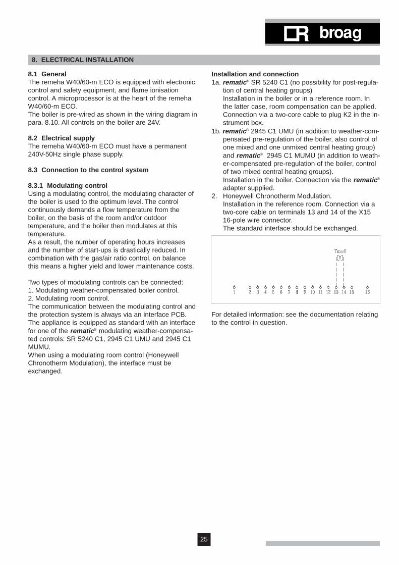
Installation in the reference room. Connection via atwo-core cable on terminals 13 and 14 of the X1516-pole wire connector.The standard interface should be exchanged.
For detailed information: see the documentation relatingto the control in question.

26
remeha W40/60-m ECO
8.3.2 Room thermostat 24VThe remeha W40/60-m ECO is suitable for a 2- or 4-wire standard room thermostat.Proceed as follows:a. Connect the room thermostat to terminals 1 and 2 of
the 16-pole wire connector.
b. Set the anticipated current of the room thermostat at 0.11 A.
8.3.3 Room thermostat in combination with an out-door temperature sensorIn order to use the modulating operation of the appliancethroughout the entire heating season using a roomthermostat, it is possible to install an outdoor tempera-ture sensor (0S). Connect the wires to terminals 10 and11 of the 16-pole wire connector. The earth slider shouldbe connected to the earth lip on the instrument panel.The appliance will now modulate at a flow temperaturerelative to the outdoor temperature (see stoking linegraph para. 10.3.3) in the event of heat demand (fromthe room thermostat).
Installation of the outdoor temperature sensorFit the outdoor sensor on a north or northwest facingwall, at a height of at least 2.5 metres from ground level.Do not install close to windows, doors or air vents,kitchen extractor, etc. and make sure the sensor is pro-tected from direct sunlight.Lay the cable to the boiler. The cable is supplied in astandard 15 metre length, and may not be extended. Ifthe cable is extended, problem-free operation cannot beguaranteed.
8.3.4 Two-stage external weather compensatorThe remeha W40/60-m ECO can be connected to a two-stage external weather-compensator. The boiler can runon high/low.Proceed as follows:a. Connect the first stage (low) to terminals 1 and 2 of
the 16-pole wire connector and the second stage (low/high) to terminals 8 and 9.
b. Set the internal control to high/low (see para 10.3.6).
8.3.5 D.H.W. controlThe D.H.W. can be connected in two different ways:Either with a standard D.H.W. thermostat (Tdhw) or witha Remeha temperature sensor (Sdhw).The installation procedure is as follows:
A. Installation with a D.H.W. thermostata. Connect the D.H.W. thermostat to terminals 3 and 4 of
the 16-pole wire connector.
b. Connect the three-way valve (230V) to the Euro-con-nector at the side of the terminal box.
c. Set the D.H.W. control (see para. 10.3.7 - 10.3.11).
b. Connect the three-way valve (230V) to the Euro-con-nector at the side of the terminal box.
c. Set the D.H.W. control (see para. 10.3.7 - 10.3.11).
B. Installation with a D.H.W. sensora. Connect the D.H.W. sensor to 11 and 12 of the 16-
pole wire connector. Connections may be inter-changed.

27
8.3.6 Frost protectionInstall the boiler in a frost-free room. If the temperatureof the central heating water drops too low, the built-infrost protection is activated.Water temperature:- below 7˚C - circulation pump is switched on;- below 3˚C - boiler is switched on;- higher than 10˚C - boiler and circulation pump are
switched off.Attention:This is only a protection of the boiler.It is recommended to install a frost thermostat (Tf) infrost-sensitive rooms and connect it to terminals 13 and14 of the 16-pole wire connector.
8.3.7 SignalsThe boiler is supplied with remote alarm and boiler runsignalling facility. The alarm signal operates via termi-nals 6 and 7 and whilst the boiler is operational a 24VAC signal (power 4 VA) is available to energise a relay.In case of failure of any electrical interlock or mainsfailure the 24V supply will be switched off. The alarm,which is de-activated whilst there is a power supplyfrom the relay during normal operation, is now activatedby the failure of this supply.
The boiler run light is operated via terminals 15 and 16which can also provide a 24V (4VA power) supply to arelay. The light is illuminated at the start of the pre-purge(code 1) and goes out on closure of the gas valve (code7 or 8).
Tf
When the frost thermostat cuts in, the circulation pumpwill also be switched on.The frost protection can be connected parallel to themodulating room control.

28
remeha W40/60-m ECO
8.4 Water temperature controlThe remeha W40/60-m ECO is supplied with an elec-tronic temperature control (basic setting 80˚C) with flowand return temperature sensors. The flow temperaturecan be adjusted between 20 and 90˚C.
8.5 Low-water protectionThe remeha W40/60-m ECO is supplied with a low-water protection device.Protection is provided in this appliance on the basis oftemperature measurement. By modulating back at themoment that the water flow threatens to fall too low, theappliance is kept operating for as long as possible. Inthe event of low flow, the appliance is switched off.
8.6 High limit temperature protectionThe high limit temperature protection device switches offand locks out the boiler when the water temperature istoo high (100˚C). When the malfunction is corrected, theboiler can be restarted by using the 'reset'-key on thecontrol panel.
8.7 Differential air pressure switch (LD2)At the start of a heat demand, the appliance first checkswhether the LD2 is open. If so, the fan switches to amonitoring speed, and waits until the LD2 is closed.Subsequently, the LD2 function will no longer be active.
8.8 Control boxManufacture: GasmodulModel: MCBA 1460 D - V.2.0Supply voltage: 240 V/50 HzElectrical rating: 10 VAPre-purge time: 0,3 secondsPost-purge time: 10 secondsSafety time: 3 secondsAnti-hunting time: 150 secondsPump operation in central heatingmode continued for: 1 - 15 minutesPump operation in D.H.W. modecontinued for: 5 minutes
8.9 Fuse specificationFuse: F1 3.15 A T
F2 3.15 A TF3 2 A F (sand-filled)
Fig. 17 Gasmodul control box
There is a glass type fuse F4 - 2 A T in the socket.
Fig. 18 Sticker on socket
transformerignition
printed circuit board

29
8.10 Electrical wiring diagram
Fig. 19 Electrical wiring diagram
30
remeha W40/60-m ECO
9. INSTALLATION INSTRUCTIONS FOR THE GAS INSTALLER
9.1 Gas connectionThe boiler is suitable for firing on natural gas andpropane.Category II2H 3P.Connect the boiler to the incoming gas in accordancewith the requirements of the Gas supply company. Installthe main gas cock near the boiler. The gas connection islocated at the bottom of the boiler (see fig. 6, para. 6.1,item 29). Fit a gas filter in the gas supply piping to avoidfouling of the gas control unit.
9.2 Gas pressuresThe required initial inlet pressure is 17-30 mbar. Theburner pressure has been factory-set but must bechecked and re-adjusted to site conditions by anapproved engineer. Consult our Technical Sales Depart-ment for other types of natural gas.
9.3 Gas/air ratio controlThe boiler is equipped with a gas/air ratio control.The purpose of this control is to keep the ratio betweengas and air quantities in the burner within safe limits, atvarying loads. This ensures clean and reliable combus-tion over the entire load range.The air flow is controlled by the differential pressureacross the fan.The gas flow will be adjusted proportionally according tochanges in the air flow.The ratio between gas and air flow can be adjusted tosuit the installation (see para. 10.1).

31
10. COMMISSIONING
10.1 Initial lighting1.Check that the electric power to the boiler is
switched off.2.Remove the front panel and the two side panels.3.Check that the gas supply is correctly fitted.4.Check that the electrical connections are correct.5.Open the cap of the automatic air vent (fig. 6, no 10).6.Fill the boiler and the installation with water and
check the water pressure (recommended 1.5 bar).7.Only remeha W40-m ECO: Check the pump; this
may be stuck. If necessary, release with a screwdriver.8. If necessary, vent the heat exchanger; the manual air
vent is mounted inside the air box (fig. 06, no. 14).Only remeha W40-m ECO: Also remember the built-incirculation pump. This should be vented separately.
9.Vent the installation.10. Fill the siphon with water.11. Check the flue and the air inlet ducting.12. Open the gas cock and vent the piping.13. Switch the electric power switch on ('1').14. Set the room thermostat or external boiler controls to
call for heat or over-ride.15. Switch on the boiler burner switch ('1').16. The following run sequence will show in the 'code'-
display:5 = Check air transport: after checking the air
pressure switch in rest mode, the fan will turn, and the appliance will wait until air transport is sufficient, or until the three-way valve has been bypassed, in the event of heat demand.
1 = Pre-ventilation: 0.3 seconds (post-ventilation:following operation of the appliance, post-ventilation will be carried out for 10 seconds).
2 = Ignition: for 2.4 seconds ignition will be switched on and the gas valve opened, thus igniting the burner.
3 = Appliance in central heating operation.4 = Appliance in boiler operation; the three-way
valve to the boiler or the boiler pump has been activated.
The following operating situations are now possible:16a.Modulating operation:
The appliance will modulate at the flow temperaturerequested by the modulating regulator (see also'Note' under 16c).
16b.High/low operation: The appliance is operating atpart-load or full-load depending on the heatdemand.
16c.On/off operation: The appliance will modulatebetween minimum and maximum load on the basisof the flow temperature preset on the appliance.
Note:Except immediately after the power has beenswitched on and if the appliance has had no heatdemand for more than 2 hours, the appliance willfirst burn at forced part-load. The factory setting forforced part-load time is 0 minutes. This setting iscorrect if use is made of modulating regulators (see16a). For on/off operation, a forced part-load time of3 minutes is recommended (setting mode, step G,see para. 6.4.1 and 6.4.3).
16d.D.H.W. operation: The warm water production takesprecedence. The appliance modulates on the basisof a preset flow temperature (setting range 70 to90°C).
17a.Check the boiler for correct function in full load andpart load.The best way to check whether the gas/air ratiocon-trol is functioning correctly, is to measure O2 inthe flue gas discharge pipe P7, see fig. 20 (CO2
measuring based on O2 measurement is also possi-ble). Direct measurement of CO2 can lead to devia-tion of the reading due to mixing CO2 in the naturalgas.Proceed as follows:Connect the measurement equipment (check for airtight).
17b.Run appliance at full-load (forced mode ‘HIGH’paragraph 6.4.5).- Press 'mode'and '▲' keys simultaneously.
Fig. 20 Measurement points

32
remeha W40/60-m ECO
17d.Run the appliance at part-load (forced mode ‘LOW’,see par. 6.4.6)- Press the 'mode' and '▼' keys simultaneously.
17e.Once the part-load speed is reached, compare themeasured result with the table above (see 17c).If necessary, correct the gas to air ratio using screwB on the gas combination block (see fig. 21).Check via the inspection opening:- the flame (should not blow out)- the burner surface (should show a regular flame
distribution).17f. Once you have adjusted gas flow in part-load, the
setting values for full-load should be checked.These values are subject to minimal variations; ifnecessary, correct the values and repeat thisprocess from point 17b onwards, as often as isneccessary, until the desired effect is achieved.
17g.Remove the measurement connections. Close themeasurement openings. Fit the boiler panels.
18. Heat the installation up to 80˚C and shut-off theboiler.
19. Vent the piping and check the water pressure.20. Set the room thermostat or weather compensator at
the required value.21. The boiler is now ready for use.
Note:The remeha W40/60-m ECO is supplied with a numberof basic settings:- burner control - on/off or
modulating- flow temperature - 80°C- post-running time pump - 5 minutes- D.H.W. control - operating- D.H.W. temperature - 65°C- D.H.W. cut-in temperature differential - 5°CIf other setting values are required: see alteration of set-tings, par. 10.3.
10.2 Shut-down1. Switch off the boiler burner switch ('0').2. Close the gas cock.3. Switch the electric power switch off.
Note:When the boiler is shut-down, it is not protected againstfrost!
A - Setting screw full loadB - Setting screw part load
Fig. 21 Setting screws
17c.When full-load speed is reached, you should com-pare the measured result with the figures in thetable below:- If necessary, correct the gas/air ratio using screw
A on the gas combination block (see fig. 21).Check the flame via the inspection opening:- the flame should not blow out- the burner surface should not glow red.
W40-m
W60-m
boilermodel
kW
input
18.662.1
12.742.3
4.84.8
%
O2
4.84.8
9.09.0
%
CO2
9.09.0
fanspeed
approx. 3000approx. 4900
approx. 3000approx. 4900
rpm
33
10.3 Settings
10.3.1 GeneralIn this paragraph a number of further setting options areexplained briefly. In most cases reference is merelymade to the diagram in par. 6.4.1.
10.3.2 Setting the required flow temperatureSetting mode, step 1.Preset 80˚C.Change setting: see para. 6.4.1 and 6.4.10.
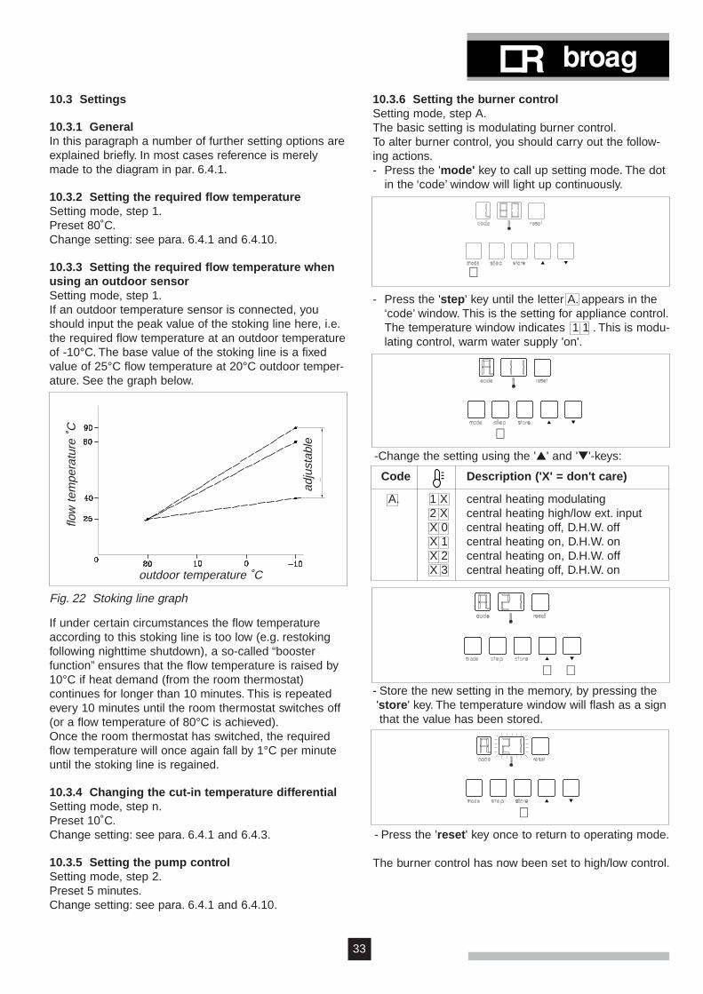
10.3.3 Setting the required flow temperature whenusing an outdoor sensorSetting mode, step 1.If an outdoor temperature sensor is connected, youshould input the peak value of the stoking line here, i.e.the required flow temperature at an outdoor temperatureof -10°C. The base value of the stoking line is a fixedvalue of 25°C flow temperature at 20°C outdoor temper-ature. See the graph below.
Fig. 22 Stoking line graph
adju
stab
le
flow
tem
pera
ture
˚C
outdoor temperature ˚C
If under certain circumstances the flow temperatureaccording to this stoking line is too low (e.g. restokingfollowing nighttime shutdown), a so-called “boosterfunction” ensures that the flow temperature is raised by10°C if heat demand (from the room thermostat)continues for longer than 10 minutes. This is repeatedevery 10 minutes until the room thermostat switches off(or a flow temperature of 80°C is achieved).Once the room thermostat has switched, the requiredflow temperature will once again fall by 1°C per minuteuntil the stoking line is regained.
10.3.4 Changing the cut-in temperature differentialSetting mode, step n.Preset 10˚C.Change setting: see para. 6.4.1 and 6.4.3.
10.3.5 Setting the pump controlSetting mode, step 2.Preset 5 minutes.Change setting: see para. 6.4.1 and 6.4.10.
10.3.6 Setting the burner controlSetting mode, step A.The basic setting is modulating burner control.To alter burner control, you should carry out the follow-ing actions.- Press the 'mode' key to call up setting mode. The dot
in the ‘code’ window will light up continuously.
⇑
- Press the 'step' key until the letter A. appears in the‘code’ window. This is the setting for appliance control.The temperature window indicates 1 1 . This is modu-lating control, warm water supply 'on'.
⇑-Change the setting using the '▲' and '▼'-keys:
⇑ ⇑
⇑- Press the 'reset' key once to return to operating mode.
The burner control has now been set to high/low control.
- Store the new setting in the memory, by pressing the 'store' key. The temperature window will flash as a signthat the value has been stored.
Code Description ('X' = don't care)
A. 1 X central heating modulating2 X central heating high/low ext. input X 0 central heating off, D.H.W. off X 1 central heating on, D.H.W. onX 2 central heating on, D.H.W. offX 3 central heating off, D.H.W. on

34
remeha W40/60-m ECO
10.3.7 Setting D.H.W. temperatureSetting mode, step 3.Setting this value is only important if a remeha D.H.W.sensor is used.The basic setting is: D.H.W. operation with a D.H.W. tem-perature of 65°C.To make alterations, see para. 6.4.1 and 6.4.10.
10.3.8 Switching D.H.W. operation on and offSetting mode, step A.The basic setting is: boiler operation on. To switch off theD.H.W. function, you should carry out the actions below:- Using the 'mode' key, go to setting mode (the dot in
the 'code' display will light up continuously).
- Press the 'step' key until the letter A. appears in the 'code' display.
⇑
- Change the setting using the '▲' and '▼' keys:
⇑ ⇑
- Store the new setting in the memory by pressing the'store' key. The temperature window will flash as asign that the value has been stored.
⇑ ⇑
- Press the 'reset' key to return to operating mode.
Code Description ('X' = don't care)
A. 1 X central heating modulating2 X central heating high/low ext. input X 0 central heating off, D.H.W. off X 1 central heating on, D.H.W. onX 2 central heating on, D.H.W. offX 3 central heating off, D.H.W. on
Note:In the factory, the control has been set so that the appli-ance will switch off if the measured D.H.W. temperatureis 5°C (preset value) above the preset boiler tempera-ture. The appliance switches back on at a temperature5°C below the shutoff point, i.e. at the boiler tempera-ture set by yourself. This cut-in temperature differentialcan be adjusted to a maximum of 20°C. To alter thisvalue, follow the instructions in par. 10.3.9.If you do not wish to change the value, installation isnow finished.
10.3.9 Changing D.H.W. operating cut-in tempera-ture differential (service level)Setting mode, step b.Preset 5˚C.Change setting: see para. 6.4.1 and 6.4.3.
Note:When using a D.H.W. thermostat, the value of the cut-indifferential is used as a switch differential for flow tem-perature in the event of an appliance control stop inD.H.W. operation.
10.3.10 Changing maximum flow temperatureduring D.H.W. operation(service level)Setting mode, step I.Preset 80˚C.Change setting: see para. 6.4.1 and 6.4.3.
10.3.11 Changing three-way valve/boiler pumpsetting(service level)Setting mode, step J.Preset three-way valve.Change setting: see para. 6.4.1 and 6.4.3.
⇑
⇑

35
11. FAULT-FINDING
11.1 GeneralThis chapter differentiates between appliances with themodulating rematic® weather-compensated control andappliances controlled in some other way.In those cases where a modulating room control(Honeywell Chronotherm Modulation with relevantinterface) is used, follow par. 11.2.
11.2 Faults in appliances in combination with therematic® weather-compensated boiler controlCarry out the steps listed below in the order given:1. No figures appear in the appliance display.
Check: - the mains voltage 240 V- the control box fuses
2. Is there a fault code on the appliance display (figuresflashing)?If yes, continue at par. 11.4.
3. Check the operating mode of the appliance (see par.6.4.2).- ‘0’ (no heat demand): continue with point 4.- ‘1’ to ‘9’, ‘H’, ‘L’: try to find the cause of the fault,according to the operating mode shown.
4. Check the operation of the appliance by connecting awire bridge to the 16-pole wire connector X15between terminals 1 and 2 (B1).Does the appliance start up?Yes, go on to point 5.No, check the wiring of the wire connector. If the wiringis correct, replace the control box.
5. Open the instrument cupboard. This cupboard con-tains an interface PCB (see fig. 23) for the modulatingrematic® control. The PCB also includes two LEDs.
There are now four possibilities:1. Neither LED is flashing:
Check whether connections L and N of the PCB(screw clamp X1) are being fed 230V.No: check the wiring.Yes: replace the interface PCB.
2. LED B (see fig. 23) is not flashing.First check the wiring between the appliance and therematic® control.Then, if necessary, replace the rematic® control. If thefault has still not been corrected, replace the interfacePCB.
3. LED A (see fig. 23) is not flashing:Check whether the tape cable connector (X7) is cor-rectly mounted in the interface PCB and in the controlbox.Then, if necessary, replace the interface PCB. If thefault has still not been corrected, replace the controlbox.
4. Both LEDS are flashing. This indicates that the instal-lation is operating correctly.Check the settings of the rematic® control. Refer to theinstructions for the control.
Fig. 23 Interface PCB for modulating rematic® control
11.3 Faults in appliances without a modulatingrematic® weather-compensated boiler controlIn the event of faults the following situations may occur:1.No figures appear on the display.
Check: - mains voltage 240V- fuses in the control box.
2.The appliance will not start up (no error message):Check whether the room thermostat or weather-com-pensated boiler control:
- are correctly connected- are correctly set- are faulty.
3.Check the operation of the appliance by connecting awire bridge to the 16-pole wire connector X15between terminals 1 and 2 (B1).Does the appliance start up?- Yes, continue at par. 11.4- No, check the wiring of the wire connector. If the wiring is correct, replace the control box.
11.4 Fault codesIn the event of an error message, both the 'code' dis-play and the ' ' display will flash.For an explanation of the various fault codes and theirpossible causes, refer to the table on the next page.
Note:For a readout of the most recent faults, see par. 6.4.8.
Important:Before resetting, accurately record the fault code(figures, including flashes and dots) and always pass onthis information if you request assistance. The fault codeis important for correctly and rapidly tracing the natureof the fault.

36
remeha W40/60-m ECO
Description Cause/checkpoints0 0. Flame simulation Check ionisation probe (distance 3 - 4 mm).0 1. Short-circuit 24V Check wiring.0 2. No flame a. no ignition spark (visible through inspection glass).
or no ionisation Check: - connection of ignition cable and spark plug cap.(after 3 starts) - ignition cable and electrode for breakdown.
- electrode distance; must be 3-4 mm.b. ignition spark, but no flame.
Check if: - gas cock is open.- inlet gas pressure is sufficient.- gas pipe is vented.- gas valve is energized during ignition.- electrode is fitted properly.- the gas/air ratio is not correct (see para. 10.1)- the gas pipe is not clogged or shows an assembly fault.
c. flame, but no ionisation.0 4 Control fault Voltage failure when malfunction causes interlock.0 8. Air transport a. Fouling/clogging of the air supply, flue gas discharge or heat exchanger;
b. Differential air pressure switch does not function:- differential air pressure switch defective.- gas/air connections loose or clogged.- gas/air connections mixed up.- spring loaded damper (fig. 06, pos. 7) does not open.
1 2. Control fault Fuse F1 (3.15 AT) defective.1 8. Max. water Flow temperature too high.1 9. temperature Return temperature too high.2 4. Temperature a. Flow and return temperature sensors mixed up.
sensor fault b. Flow and return connections mixed up.c. Water flow in D.H.W. mode not correct.
2 5. Maximum water Rise in flow temperature too fast.temperature Check: - circulation pump (position 1 or 2)
- water flow through the unit (sufficient number of radiators opened) - water pressure (0.8 bar min).
2 8. Fan does not run Fan defective or improperly fitted (mechanically or electrically).Fuse F2 (3.15 AT) defective.Transformer defective (power on X3?)
2 9. Fan keeps running a. electrical connections mixed up.b. electrical connections interrupted.
3 0. Max. water temp. Difference between flow and return temperature too high3 1. Temp.sensor fault Short-circuit in flow temperature sensor.3 2. Short-circuit in return temperature sensor.3 6. Flow temperature sensor defective or not connected.3 7. Return temperature sensor defective or not connected.4 3. Parameters out Check the parameter settings.
of reach6 1. Air transport Air differential switch does not open:
- Air differential switch defective- Extreme draft through flue gas discharge duct- Short-circuit in wiring.
Note:Not mentioned codes refer to internal control errors,requiring the control box to be changed.

37
12. INSPECTION AND SERVICING INSTRUCTIONS
12.1 GeneralThe remeha W40/60-m ECO is practically maintenance-free. Once a year, the appliance should be checked andif necessary cleaned.
12.2 InspectionThe annual inspection of the remeha W40/60-m ECOcan be limited to:- inspection of the boilers combustion characteristics- cleaning the siphon- setting the ignition electrode- check for leaks (water side, flue gas side and gas side)- water pressure check.
Checking the boiler combustion characteristicsThis can be done by measuring the O2 level in the fluegas (P7, fig 24). The boiler should be in equilibrium withan average boiler water temperature of approximately70°C.The flue gas temperature can also be taken at P7.This flue gas temperature must not exceed the returnwater temperature by more than 30°C.If this check shows the operation of the unit to havedeteriorated clean the boiler as detailed in para. 12.3.
Fig. 24 Measuring points
W40-m
W60-m
boilermodel
kW
input(NCV)
18.662.1
12.742.3
4.84.8
%
O2
4.84.8
9.09.0
%
CO2
9.09.0
fanspeed
approx. 3000approx. 4900
approx. 3000approx. 4900
rpm
The above values apply to a closed air box.See also para. 10.1 for initial settings.
Cleaning the siphonRemove the siphon and clean it. Fill the siphon withclean water and fit it.
Setting the ignition electrodeCheck the setting of the ignition electrode (3-4 mm).
Water pressure checkThe water pressure should be at least 0.8 bar. You arerecommended to fill the appliance to approx. 1.5 bar.

38
remeha W40/60-m ECO
12.3 MaintenanceIf the appliance is checked for technical combustionproblems and the result is that either combustion orheat exchanger are no longer at the optimum level,maintenance should be carried out. This maintenancewill consist of:- cleaning the heat exchanger with a nylon brush or
compressed air and possibly rinsing with water- cleaning the fan- cleaning the siphon.
Work order (see fig. 26):- Switch off the appliance via the burner switch on the
instrument panel on the front.- Disconnect the electrical power supply to the
appliance.- Close the cock in the gas pipe to the appliance.- Remove the front cover and the two side covers.- Open the catch on the instrument panel and tilt the
panel forwards.
Attention:To prevent a short-circuit in the external connections orin the instrument panel as a result of the unexpectedpenetration of leak water, you are advised to cover theinstrument panel.
- Remove the cover from the air box.- Remove the pipes (E) from the inlet mixer.- Open the union nut for the gas pipe in the air box (A).
Remember!!!To prevent the flexible gas pipe twisting, when slacken-ing and tightening the union nut (A1), the hexagon nut(A2) should be held in place with a spanner, see fig. 25.
Fig. 25 ((Dis)assembly of the gas pipe
- Remove the bolts from the attachment strips (B). Thefastening strips can then be removed.
- Remove the electrical connection from the fan (D).- Lift the burner from the fan carefully upwards and
remove the burner from the appliance.- Check the burner seal on the heat exchanger.
If damaged or hardened, replace the seal(recommended: replace every 3 years).
Attention:The metal-fibre layer on the burner is susceptible tomechanical damage and should therefore be handledwith care. Do not touch with brushes or other sharpobjects.
- To inspect/clean the heat exchanger, the hold-downstrips (F) on the underside and sides must be removed(brass wing nuts). Also remove the 3 metal screws onthe underside of the inspection plate (G).
- Now remove the inspection plate (H).- If necessary, remove the 3 guide plates (I) between the
aluminium finned pipes, in order to clean the finnedpipes.
A2
A1

39
FH
B
I
B
J
K
M
C
L
G G
E
Fig. 26 Servicing points remeha W40/60-m ECO A Union nutB Fastening stripsC Ignition cableD Connecting plugE Hose connectionF Hold down stripsG Metal screwsH Inspection plateI Guide plateJ Condense collectorK Filling and drain cockL Automatic vent.M Manual air vent.
D
A
G
- To inspect or clean the fan, it must be disconnectedfrom the gas injector.
- Remove the screws at the rear of the fan.For cleaning purposes, use a plastic brush; removeany loose dust particles from the fan, before reassem-bling the system.
- Reassemble all parts removed in reverse order.
Attention:Check that all control hoses are properly fitted followingassembly: in the event of incorrect assembly, it is notpossible to guarantee the correct setting of the gas/airratio.
- Check the setting of the ignition electrode (between 3and 4 mm).
- Restart the appliance.
12.4 Draining and fillingThe fill and drain cock is fitted at the bottom of the boiler.
12.5 VentingThe boiler is equipped with an air separator with auto-matic vent. Give the sealing cap a quarter turn.A manual vent is fitted top right on the heat exchanger.

remeha W40/60-m ECO
Subject to alterationsArt. nr. 51.794/2500/05.97/Ho.
© CopyrightAll technical and technological infor-mation contained in these technicalinstructions, as well as any drawingsand technical descriptions furnishedby us remain our property and shallnot be multiplied without our priorconsent in writing.
Broag Ltd.Head OfficeRemeha house,Molly Millars Lane,Wokingham,Berkshire RG 41 2QP.Tel. 0118 9786977Fax 0118 9783434Email address:[email protected].
Branch OfficeUnit 3,Kestrel Close,Quarry Hill Industrial Estate,IlkestonDerbyshire DE7 4RDTel. 0115 9440778Fax 0115 9440588
ISO 9001since 1988