wall mounted condensing boiler for central heating installation and servicing...
TRANSCRIPT
GREENSTARWALL MOUNTED CONDENSING BOILER FOR CENTRAL HEATING
AND MAINS FED DOMESTIC HOT WATER
INSTALLATION AND
SERVICING INSTRUCTIONS
GC NUMBERSGreenstar ZWBR 7-25 A23 (N.G.) 47 311 44
Greenstar ZWBR 11-25 A31 (L.P.G.) 47 311 45
THIS APPLIANCE IS FOR USE ON SEALED PRIMARY SYSTEMS ONLY
IMPORTANT: THESE INSTRUCTIONS APPLY IN THE UK ONLYTHESE INSTRUCTIONS ARE TO BE LEFT WITH THE USER OR AT THE GAS METER
This appliance must be installed by a competent person in accordancewith the Gas Safety (Installation and Use) Regulations 1998
Cat II appliance2H 3P
2
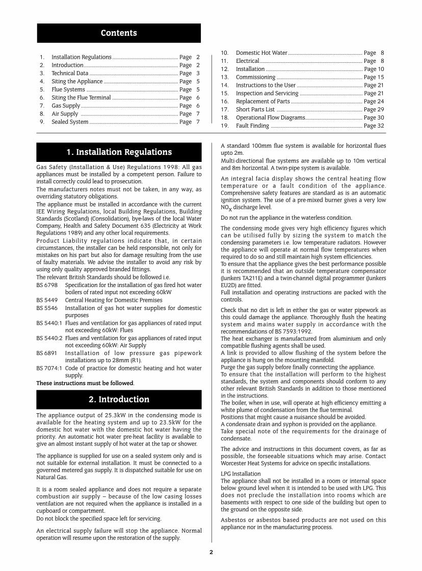
10. Domestic Hot Water .................................................... Page 811. Electrical........................................................................ Page 812. Installation .................................................................... Page 1013. Commissioning ............................................................ Page 1514. Instructions to the User .............................................. Page 2115. Inspection and Servicing ............................................ Page 2116. Replacement of Parts .................................................. Page 2417. Short Parts List ............................................................ Page 2918. Operational Flow Diagrams........................................ Page 3019. Fault Finding ................................................................ Page 32
1. Installation Regulations .............................................. Page 22. Introduction.................................................................. Page 23. Technical Data .............................................................. Page 34. Siting the Appliance .................................................... Page 55. Flue Systems ................................................................ Page 56. Siting the Flue Terminal .............................................. Page 67. Gas Supply.................................................................... Page 68. Air Supply .................................................................... Page 79. Sealed System .............................................................. Page 7
Contents
Gas Safety (Installation & Use) Regulations 1998: All gasappliances must be installed by a competent person. Failure toinstall correctly could lead to prosecution.The manufacturers notes must not be taken, in any way, asoverriding statutory obligations.The appliance must be installed in accordance with the currentIEE Wiring Regulations, local Building Regulations, BuildingStandards (Scotland) (Consolidation), bye-laws of the local WaterCompany, Health and Safety Document 635 (Electricity at WorkRegulations 1989) and any other local requirements.Product Liabil ity regulations indicate that, in certaincircumstances, the installer can be held responsible, not only formistakes on his part but also for damage resulting from the useof faulty materials. We advise the installer to avoid any risk byusing only quality approved branded fittings.The relevant British Standards should be followed i.e.BS 6798 Specification for the installation of gas fired hot water
boilers of rated input not exceeding 60kWBS 5449 Central Heating for Domestic PremisesBS 5546 Installation of gas hot water supplies for domestic
purposesBS 5440:1 Flues and ventilation for gas appliances of rated input
not exceeding 60kW: FluesBS 5440:2 Flues and ventilation for gas appliances of rated input
not exceeding 60kW: Air SupplyBS 6891 Installation of low pressure gas pipework
installations up to 28mm (R1).BS 7074:1 Code of practice for domestic heating and hot water
supply. These instructions must be followed.
The appliance output of 25.3kW in the condensing mode isavailable for the heating system and up to 23.5kW for thedomestic hot water with the domestic hot water having thepriority. An automatic hot water pre-heat facility is available togive an almost instant supply of hot water at the tap or shower.
The appliance is supplied for use on a sealed system only and isnot suitable for external installation. It must be connected to agoverned metered gas supply. It is dispatched suitable for use onNatural Gas.
It is a room sealed appliance and does not require a separatecombustion air supply – because of the low casing lossesventilation are not required when the appliance is installed in acupboard or compartment.Do not block the specified space left for servicing.
An electrical supply failure will stop the appliance. Normaloperation will resume upon the restoration of the supply.
A standard 100mm flue system is available for horizontal fluesupto 2m.Multi-directional flue systems are available up to 10m verticaland 8m horizontal. A twin-pipe system is available.
An integral facia display shows the central heating flowtemperature or a fault condition of the appliance.Comprehensive safety features are standard as is an automaticignition system. The use of a pre-mixed burner gives a very lowNOx discharge level.
Do not run the appliance in the waterless condition.
The condensing mode gives very high efficiency figures whichcan be util ised fully by sizing the system to match thecondensing parameters i.e. low temperature radiators. Howeverthe appliance will operate at normal flow temperatures whenrequired to do so and still maintain high system efficiencies.To ensure that the appliance gives the best performance possibleit is recommended that an outside temperature compensator(Junkers TA211E) and a twin-channel digital programmer (JunkersEU2D) are fitted.Full installation and operating instructions are packed with thecontrols.
Check that no dirt is left in either the gas or water pipework asthis could damage the appliance. Thoroughly flush the heatingsystem and mains water supply in accordance with therecommendations of BS 7593:1992.The heat exchanger is manufactured from aluminium and onlycompatible flushing agents shall be used.A link is provided to allow flushing of the system before theappliance is hung on the mounting manifold.Purge the gas supply before finally connecting the appliance.To ensure that the installation will perform to the higheststandards, the system and components should conform to anyother relevant British Standards in addition to those mentionedin the instructions.The boiler, when in use, will operate at high efficiency emitting awhite plume of condensation from the flue terminal.Positions that might cause a nuisance should be avoided.A condensate drain and syphon is provided on the appliance.Take special note of the requirements for the drainage ofcondensate.
The advice and instructions in this document covers, as far aspossible, the forseeable situations which may arise. ContactWorcester Heat Systems for advice on specific installations.
LPG InstallationThe appliance shall not be installed in a room or internal spacebelow ground level when it is intended to be used with LPG. Thisdoes not preclude the installation into rooms which arebasements with respect to one side of the building but open tothe ground on the opposite side.
Asbestos or asbestos based products are not used on thisappliance nor in the manufacturing process.
2. Introduction
1. Installation Regulations
3
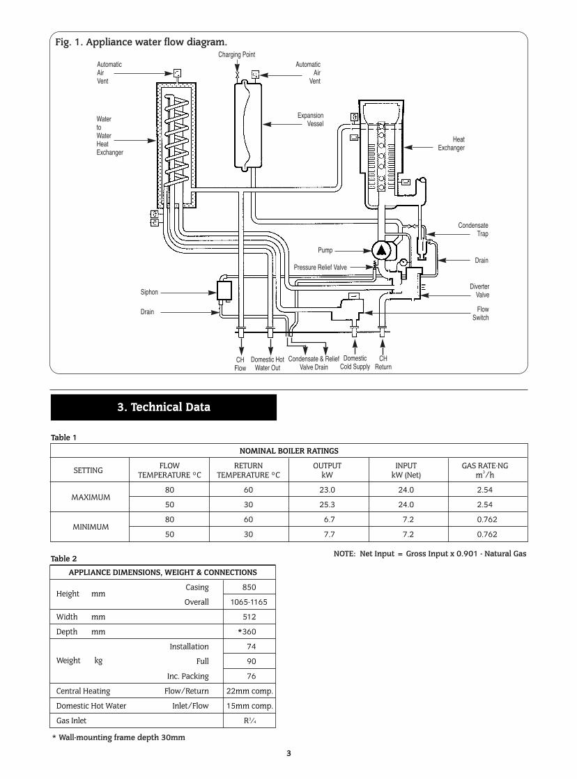
APPLIANCE DIMENSIONS, WEIGHT & CONNECTIONS
Height mmCasing 850
Overall 1065-1165
Width mm 512
Depth mm *360
Weight kg
Installation 74
Full 90
Inc. Packing 76
Central Heating Flow/Return 22mm comp.
Domestic Hot Water Inlet/Flow 15mm comp.
Gas Inlet R3⁄4
Table 2
NOMINAL BOILER RATINGS
SETTING FLOW RETURN OUTPUT INPUT GAS RATE-NGTEMPERATURE °C TEMPERATURE °C kW kW (Net) m3/h
MAXIMUM80 60 23.0 24.0 2.54
50 30 25.3 24.0 2.54
MINIMUM80 60 6.7 7.2 0.762
50 30 7.7 7.2 0.762
Table 1
3. Technical Data
Fig. 1. Appliance water flow diagram.
Automatic Air Vent
Water to WaterHeatExchanger
Automatic Air
Vent
Charging Point
Expansion Vessel
Heat Exchanger
CondensateTrap
Drain
Diverter Valve
FlowSwitch
Siphon
Drain
Pump
Pressure Relief Valve
Domestic HotWater Out
CHFlow
Condensate & Relief Valve Drain
Domestic Cold Supply
CH Return
NOTE: Net Input = Gross Input x 0.901 - Natural Gas
* Wall-mounting frame depth 30mm
4
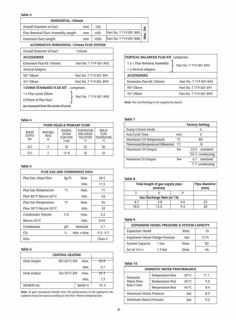
FLUE GAS AND CONDENSATE DATA
Flue Gas, Mass Flow kg/h Max. 38.5
Min. 11.5
Flue Gas Temperature °C Max. 71
Flow 80°C Return 60°C Min. 62
Flue Gas Temperature °C Max. 36
Flow 50°C Return 30°C Min. 32
Condensate Volume l/h Max. 2.2
Return 30°C Min. 0.94
Condensate pH Nominal 4.1
CO2 % Min,=Max. 9.3 - 9.7
NOx Class 5
Table 5
PUMP HEAD & PRIMARY FLOW
BOILER AVAILABLE NOMINAL TEMPERATURE BOILEROUTPUT HEAD SYSTEM RISE ACROSS FLOW
kW m FLOW RATE THE SYSTEM TEMPERATUREl/min °C °C
23.5 2 20 20 80
25.3 2 16-18 20 50
Table 4
CENTRAL HEATING
Heat Output 80/60°C kW Max. 23.5
Min. 6.7
Heat Output 50/30°C kW Max. 25.3
Min. 7.7
SEDBUK No. BAND A 91.3
Table 6
Note: To gain maximum benefit from the performance of the appliance theradiators must be sized according to the Flow/Return temperatures.
Total length of gas supply pipe Pipe diameter(metres) (mm)
3 6 9Gas Discharge Rate (m3/h)
8.7 5.8 4.6 2218.0 12.0 9.4 28
Table 8
EXPANSION VESSEL PRESSURE & SYSTEM CAPACITY
Expansion Vessel litres 10
Expansion Vessel Charge Pressure bar 0.75
System Capacity 1 bar litres 82
Ref. BS 7074:1 1.5 bar litres 46
Table 9.
DOMESTIC WATER PERFORMANCE
DomesticTemperature Rise 30°C 11.1
Water Flow Temperature Rise 35°C 9.5Rate l/min
Temperature Rise 40°C 8.4
Maximum Mains Pressure bar 8.0
Minimum Mains Pressure bar 0.2
Table 10
Factory SettingPump Control Mode 2Anti-Cycle Time min 3Maximum CH Temperature °C 80ThermostatTemperature Differential °C 8Maximum CH Output kw 23.0 standard
25.3 condensingMinimum CH Output kw 6.7 standard
7.7 condensing
Table 7
HORIZONTAL 100mm
Overall Diameter of Duct mm 100
Flue Terminal/Duct Assembly Length mm 600
Extension Duct Length mm 1000
Overall Diameter of Duct 125mm
ACCESSORIES
Extension Flue Kit 100mm Part No. 7 719 001 892
Vertical Adaptor
90° Elbow Part No. 7 719 001 891
45° Elbow Part No. 7 719 001 899
125MM STANDARD FLUE KIT comprises:
1 x Flue turret Elbow
670mm of Flue Duct
(as measured from the centre of turret)
Table 3
ALTERNATIVE HORIZONTAL 125mm FLUE SYSTEM
VERTICAL BALANCED FLUE KIT comprises:
1 x 1 Flue Terminal Assembly
1 x Vertical Adaptor
ACCESSORIES
Extension Flue Kit 100mm Part No. 7 719 001 892
90° Elbow Part No. 7 719 001 891
45° Elbow Part No. 7 719 001 899
Part No. 7 719 001 885
Part No. 7 719 001 888 Max
. 2m
Part No. 7 719 001 890
Part No. 7 719 001 890
Note: The roof flashing is not supplied by Bosch.
The appliance is not suitable for external installation.
The appliance may be installed in any room subject to therequirements of the IEE Wiring Regulations or the electricalprovisions of the Building Regulations applicable in Scotlandrelevant to appliances fitted in rooms containing baths orshowers. It must not be possible for anyone using the bath orshower to touch any control using mains electricity.
No special wall protection is required. Ensure that the wall cansupport the appliance. Refer to the IGE publication “Guide forGas Installations in Timber Framed Housing” where appropriate,IGE/UP/7:1998.
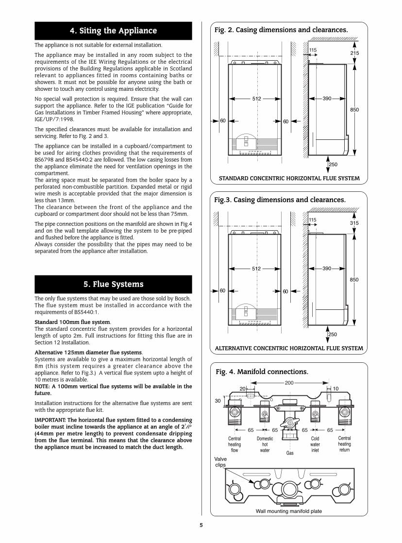
The specified clearances must be available for installation andservicing. Refer to Fig. 2 and 3.
The appliance can be installed in a cupboard/compartment tobe used for airing clothes providing that the requirements ofBS6798 and BS45440:2 are followed. The low casing losses fromthe appliance eliminate the need for ventilation openings in thecompartment.The airing space must be separated from the boiler space by aperforated non-combustible partition. Expanded metal or rigidwire mesh is acceptable provided that the major dimension isless than 13mm.The clearance between the front of the appliance and thecupboard or compartment door should not be less than 75mm.
The pipe connection positions on the manifold are shown in Fig.4and on the wall template allowing the system to be pre-pipedand flushed before the appliance is fitted.Always consider the possibility that the pipes may need to beseparated from the appliance after installation.
The only flue systems that may be used are those sold by Bosch.The flue system must be installed in accordance with therequirements of BS5440:1.
Standard 100mm flue system.The standard concentric flue system provides for a horizontallength of upto 2m. Full instructions for fitting this flue are inSection 12 Installation.
Alternative 125mm diameter flue systems.Systems are available to give a maximum horizontal length of8m (this system requires a greater clearance above theappliance. Refer to Fig.3.) A vertical flue system upto a height of10 metres is available. NOTE: A 100mm vertical flue systems will be available in thefuture.
Installation instructions for the alternative flue systems are sentwith the appropriate flue kit.
IMPORTANT: The horizontal flue system fitted to a condensingboiler must incline towards the appliance at an angle of 21/2°(44mm per metre length) to prevent condensate drippingfrom the flue terminal. This means that the clearance abovethe appliance must be increased to match the duct length.
5. Flue Systems
4. Siting the Appliance
5
Fig. 2. Casing dimensions and clearances.
512
60
215
850
250
STANDARD CONCENTRIC HORIZONTAL FLUE SYSTEM
60
Fig. 4. Manifold connections.
Centralheating
flow
Valveclips
Wall mounting manifold plate
Domestichot
water
Coldwaterinlet
Centralheatingreturn
Gas
30
20 10
390
Fig.3. Casing dimensions and clearances.
512
60
315
850
250
ALTERNATIVE CONCENTRIC HORIZONTAL FLUE SYSTEM
60
390
▲
▲ ▲
▲
200
▲
▲
6565 65 65▲ ▲ ▲ ▲
▲ ▲ ▲ ▲
▼
▼ 115
▼
▼ 115
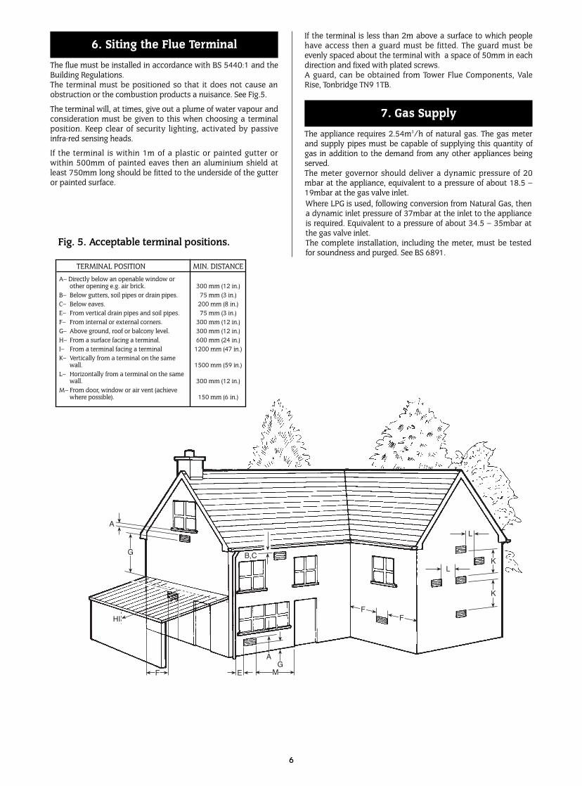
The flue must be installed in accordance with BS 5440:1 and theBuilding Regulations.The terminal must be positioned so that it does not cause anobstruction or the combustion products a nuisance. See Fig.5.
The terminal will, at times, give out a plume of water vapour andconsideration must be given to this when choosing a terminalposition. Keep clear of security lighting, activated by passiveinfra-red sensing heads.
If the terminal is within 1m of a plastic or painted gutter orwithin 500mm of painted eaves then an aluminium shield atleast 750mm long should be fitted to the underside of the gutteror painted surface.
If the terminal is less than 2m above a surface to which peoplehave access then a guard must be fitted. The guard must beevenly spaced about the terminal with a space of 50mm in eachdirection and fixed with plated screws.A guard, can be obtained from Tower Flue Components, ValeRise, Tonbridge TN9 1TB.
The appliance requires 2.54m3/h of natural gas. The gas meterand supply pipes must be capable of supplying this quantity ofgas in addition to the demand from any other appliances beingserved. The meter governor should deliver a dynamic pressure of 20mbar at the appliance, equivalent to a pressure of about 18.5 –19mbar at the gas valve inlet.
7. Gas Supply
6. Siting the Flue Terminal
L
LK
K
FF
GA
MEJF
HI
D
G
A
B,C
6
Fig. 5. Acceptable terminal positions.
TERMINAL POSITION MIN. DISTANCEA– Directly below an openable window or
other opening e.g. air brick. 300 mm (12 in.)B– Below gutters, soil pipes or drain pipes. 75 mm (3 in.)C– Below eaves. 200 mm (8 in.)E– From vertical drain pipes and soil pipes. 75 mm (3 in.)F– From internal or external corners. 300 mm (12 in.)G– Above ground, roof or balcony level. 300 mm (12 in.)H– From a surface facing a terminal. 600 mm (24 in.)I– From a terminal facing a terminal 1200 mm (47 in.)K– Vertically from a terminal on the same
wall. 1500 mm (59 in.)L– Horizontally from a terminal on the same
wall. 300 mm (12 in.)M– From door, window or air vent (achieve
where possible). 150 mm (6 in.)
Where LPG is used, following conversion from Natural Gas, thena dynamic inlet pressure of 37mbar at the inlet to the applianceis required. Equivalent to a pressure of about 34.5 – 35mbar atthe gas valve inlet. The complete installation, including the meter, must be testedfor soundness and purged. See BS 6891.
A separate air supply for combustion is not required.
If the appliance is in a cupboard or compartment then, becauseof the low casing losses, it is not necessary to have additionalventilation for the boiler.
The specified clearances around the appliance must bemaintained to allow the free movement of the air. Refer toFig.2,3.
Note: In order to prevent corrosion the air for combustion must notcontain corrosive substances such as solvents, paints, adhesives,household cleaners etc. The combustion air should be dust free toreduce the risk of the pre-mix burner becoming blocked.
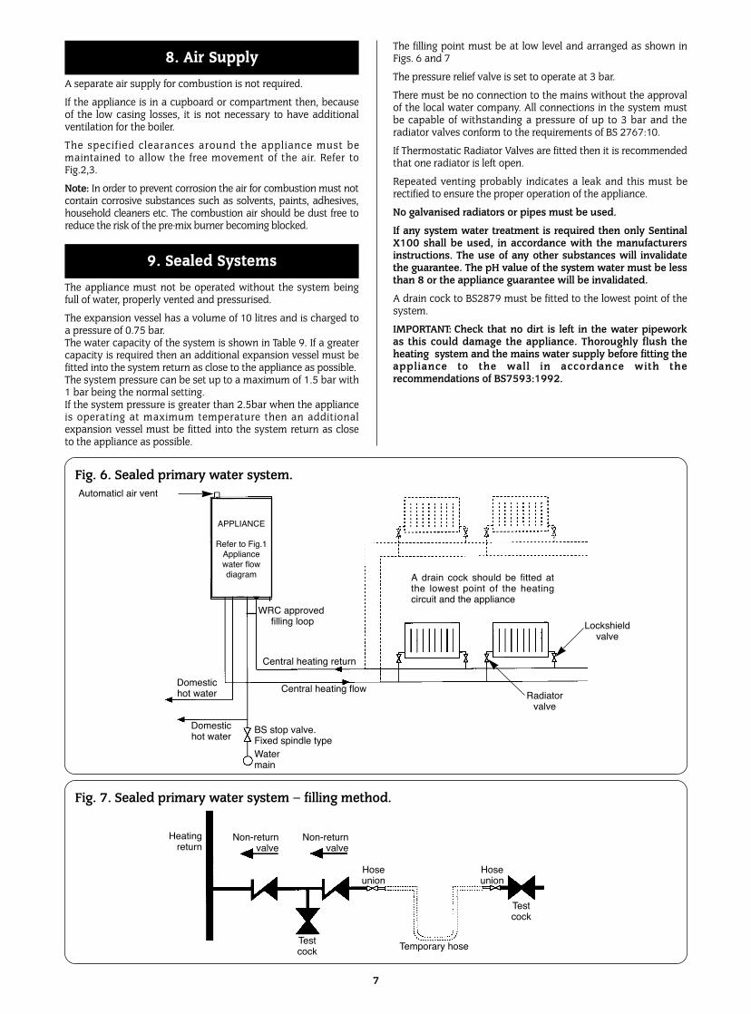
The appliance must not be operated without the system beingfull of water, properly vented and pressurised.
The expansion vessel has a volume of 10 litres and is charged toa pressure of 0.75 bar.The water capacity of the system is shown in Table 9. If a greatercapacity is required then an additional expansion vessel must befitted into the system return as close to the appliance as possible.The system pressure can be set up to a maximum of 1.5 bar with1 bar being the normal setting.If the system pressure is greater than 2.5bar when the applianceis operating at maximum temperature then an additionalexpansion vessel must be fitted into the system return as closeto the appliance as possible.
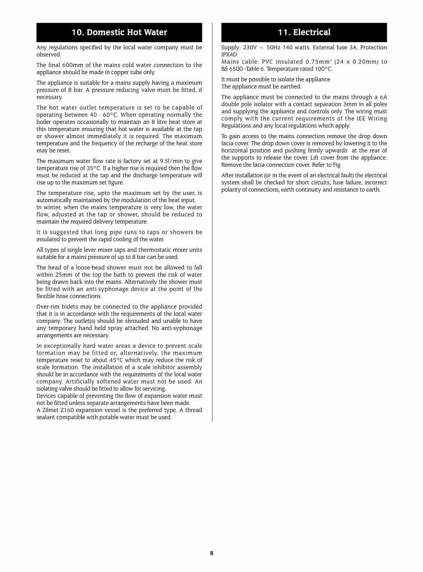
The filling point must be at low level and arranged as shown inFigs. 6 and 7
The pressure relief valve is set to operate at 3 bar.
There must be no connection to the mains without the approvalof the local water company. All connections in the system mustbe capable of withstanding a pressure of up to 3 bar and theradiator valves conform to the requirements of BS 2767:10.
If Thermostatic Radiator Valves are fitted then it is recommendedthat one radiator is left open.
Repeated venting probably indicates a leak and this must berectified to ensure the proper operation of the appliance.
No galvanised radiators or pipes must be used.
If any system water treatment is required then only SentinalX100 shall be used, in accordance with the manufacturersinstructions. The use of any other substances will invalidatethe guarantee. The pH value of the system water must be lessthan 8 or the appliance guarantee will be invalidated.
A drain cock to BS2879 must be fitted to the lowest point of thesystem.
IMPORTANT: Check that no dirt is left in the water pipeworkas this could damage the appliance. Thoroughly flush theheating system and the mains water supply before fitting theappliance to the wall in accordance with therecommendations of BS7593:1992.
9. Sealed Systems
8. Air Supply
7
Fig. 7. Sealed primary water system – filling method.
Fig. 6. Sealed primary water system.Automaticl air vent
Domestichot water
Domestichot water
Central heating flowRadiator
valve
Lockshieldvalve
Central heating return
A drain cock should be fitted atthe lowest point of the heatingcircuit and the appliance
Watermain
BS stop valve.Fixed spindle type
Heatingreturn
Non-returnvalve
Non-returnvalve
Hoseunion
Hoseunion
Testcock
Temporary hoseTestcock
APPLIANCE
Refer to Fig.1Appliancewater flow diagram
WRC approvedfilling loop
Any regulations specified by the local water company must beobserved.
The final 600mm of the mains cold water connection to theappliance should be made in copper tube only.
The appliance is suitable for a mains supply having a maximumpressure of 8 bar. A pressure reducing valve must be fitted, ifnecessary.
The hot water outlet temperature is set to be capable ofoperating between 40 - 60°C. When operating normally theboiler operates occasionally to maintain an 8 litre heat store atthis temperature ensuring that hot water is available at the tapor shower almost immediately it is required. The maximumtemperature and the frequency of the recharge of the heat storemay be reset.
The maximum water flow rate is factory set at 9.5l/min to givetemperature rise of 35°C. If a higher rise is required then the flowmust be reduced at the tap and the discharge temperature willrise up to the maximum set figure.
The temperature rise, upto the maximum set by the user, isautomatically maintained by the modulation of the heat input.In winter, when the mains temperature is very low, the waterflow, adjusted at the tap or shower, should be reduced tomaintain the required delivery temperature.
It is suggested that long pipe runs to taps or showers beinsulated to prevent the rapid cooling of the water.
All types of single lever mixer taps and thermostatic mixer unitssuitable for a mains pressure of up to 8 bar can be used.
The head of a loose-head shower must not be allowed to fallwithin 25mm of the top the bath to prevent the risk of waterbeing drawn back into the mains. Alternatively the shower mustbe fitted with an anti-syphonage device at the point of theflexible hose connections.
Over-rim bidets may be connected to the appliance providedthat it is in accordance with the requirements of the local watercompany. The outlet(s) should be shrouded and unable to haveany temporary hand held spray attached. No anti-syphonagearrangements are necessary.
In exceptionally hard water areas a device to prevent scaleformation may be fitted or, alternatively, the maximumtemperature reset to about 45°C which may reduce the risk ofscale formation. The installation of a scale inhibitor assemblyshould be in accordance with the requirements of the local watercompany. Artificially softened water must not be used. Anisolating valve should be fitted to allow for servicing.Devices capable of preventing the flow of expansion water mustnot be fitted unless separate arrangements have been made. A Zilmet Z160 expansion vessel is the preferred type. A threadsealant compatible with potable water must be used.
Supply: 230V ~ 50Hz 140 watts. External fuse 3A. ProtectionIPX4D.Mains cable: PVC insulated 0.75mm2 (24 x 0.20mm) toBS 6500–Table 6. Temperature rated 100°C.
It must be possible to isolate the applianceThe appliance must be earthed.
The appliance must be connected to the mains through a 6Adouble pole isolator with a contact separation 3mm in all polesand supplying the appliance and controls only. The wiring mustcomply with the current requirements of the IEE WiringRegulations and any local regulations which apply.
To gain access to the mains connection remove the drop downfacia cover. The drop down cover is removed by lowering it to thehorizontal position and pushing firmly upwards at the rear ofthe supports to release the cover. Lift cover from the appliance.Remove the facia connection cover. Refer to Fig.
After installation (or in the event of an electrical fault) the electricalsystem shall be checked for short circuits, fuse failure, incorrectpolarity of connections, earth continuity and resistance to earth.
11. Electrical10. Domestic Hot Water
8
9
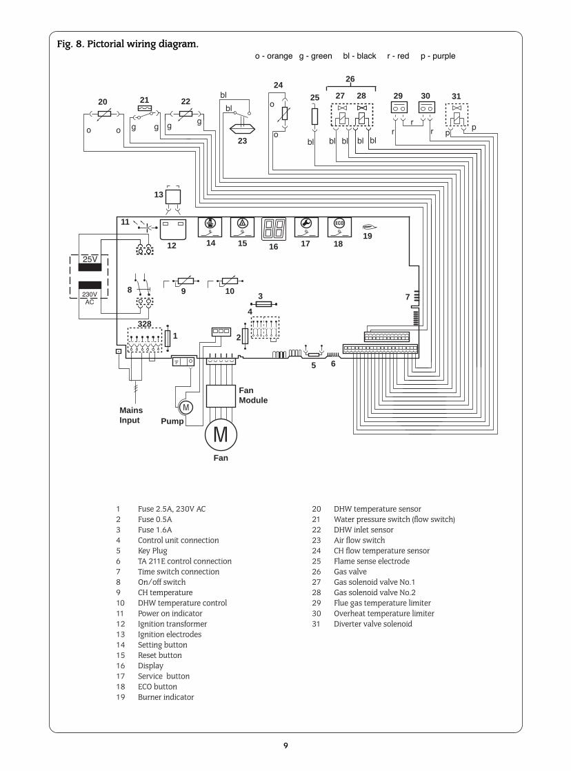
Fig. 8. Pictorial wiring diagram.o - orange g - green bl - black r - red p - purple
20 21 22
23
24
25 27 28
26
29 30 31
13
11
12 14 15 16 17 1819
8 9 103
4
7
65
2
MainsInput
328
FanModule
Pump
Fan
1
1 Fuse 2.5A, 230V AC2 Fuse 0.5A3 Fuse 1.6A4 Control unit connection5 Key Plug6 TA 211E control connection7 Time switch connection8 On/off switch9 CH temperature10 DHW temperature control11 Power on indicator12 Ignition transformer13 Ignition electrodes14 Setting button15 Reset button16 Display17 Service button18 ECO button19 Burner indicator
20 DHW temperature sensor21 Water pressure switch (flow switch)22 DHW inlet sensor23 Air flow switch24 CH flow temperature sensor25 Flame sense electrode26 Gas valve27 Gas solenoid valve No.128 Gas solenoid valve No.229 Flue gas temperature limiter30 Overheat temperature limiter31 Diverter valve solenoid
25V
230VAC
o o g g g g
bl
bl o
obl bl bl bl bl
rr
r pp
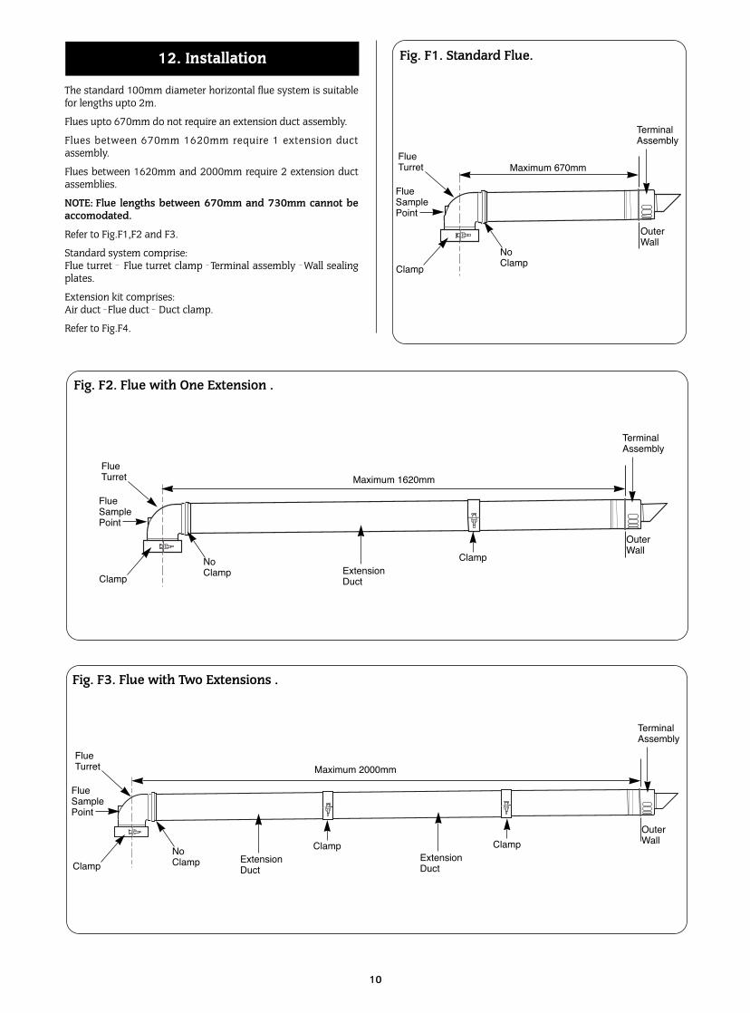
The standard 100mm diameter horizontal flue system is suitablefor lengths upto 2m.
Flues upto 670mm do not require an extension duct assembly.
Flues between 670mm 1620mm require 1 extension ductassembly.
Flues between 1620mm and 2000mm require 2 extension ductassemblies.
NOTE: Flue lengths between 670mm and 730mm cannot beaccomodated.
Refer to Fig.F1,F2 and F3.
Standard system comprise:Flue turret _ Flue turret clamp _ Terminal assembly _ Wall sealingplates.
Extension kit comprises:Air duct _ Flue duct _ Duct clamp.
Refer to Fig.F4.
10
12. Installation Fig. F1. Standard Flue.
FlueTurret
FlueSamplePoint
Clamp
No Clamp
Maximum 670mm
TerminalAssembly
OuterWall
Fig. F2. Flue with One Extension .
Maximum 1620mmFlueTurret
FlueSamplePoint
Clamp
No Clamp
Clamp
TerminalAssembly
OuterWall
Extension Duct
Fig. F3. Flue with Two Extensions .
FlueTurret
FlueSamplePoint
Clamp
No Clamp
Maximum 2000mm
ClampExtension Duct
ClampExtension Duct
TerminalAssembly
OuterWall
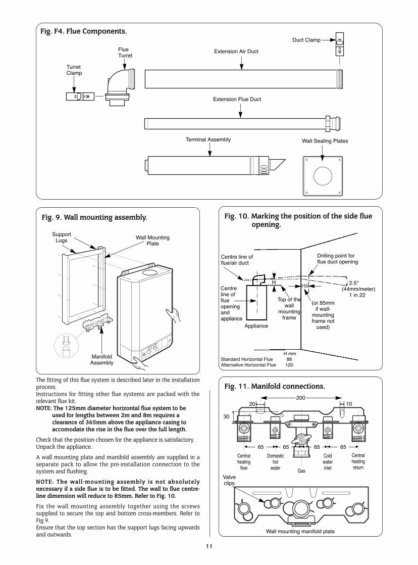
The fitting of this flue system is described later in the installationprocess.Instructions for fitting other flue systems are packed with therelevant flue kit.NOTE: The 125mm diameter horizontal flue system to be
used for lengths between 2m and 8m requires a clearance of 365mm above the appliance casing toaccomodate the rise in the flue over the full length.
Check that the position chosen for the appliance is satisfactory.Unpack the appliance.
A wall mounting plate and manifold assembly are supplied in aseparate pack to allow the pre-installation connection to thesystem and flushing.
NOTE: The wall-mounting assembly is not absolutelynecessary if a side flue is to be fitted. The wall to flue centre-line dimension will reduce to 85mm. Refer to Fig. 10.
Fix the wall mounting assembly together using the screwssupplied to secure the top and bottom cross-members. Refer toFig.9.Ensure that the top section has the support lugs facing upwardsand outwards.
11
Fig. 9. Wall mounting assembly.
Fig. 11. Manifold connections.
Centralheating
flow
Valveclips
Wall mounting manifold plate
Domestichot
water
Coldwaterinlet
Centralheatingreturn
Gas
30
20 10▲
▲ ▲
▲
200
▲
▲
6565 65 65▲ ▲ ▲ ▲
▲ ▲ ▲ ▲
SupportLugs
ManifoldAssembly
Wall MountingPlate
Fig. 10. Marking the position of the side flue opening.
Appliance
115
Drilling point forflue duct opening
2.5¡(44mm/meter)
1 in 22Centreline offlueopeningandappliance
H
H mmStandard Horizontal Flue 88Alternative Horizontal Flue 120
Centre line offlue/air duct
Fig. F4. Flue Components.
FlueTurret
TurretClamp
Extension Air Duct
Extension Flue Duct
Terminal Assembly
Duct Clamp
Wall Sealing Plates
Top of thewall
mountingframe
(or 85mmif wall-
mountingframe not
used)
12
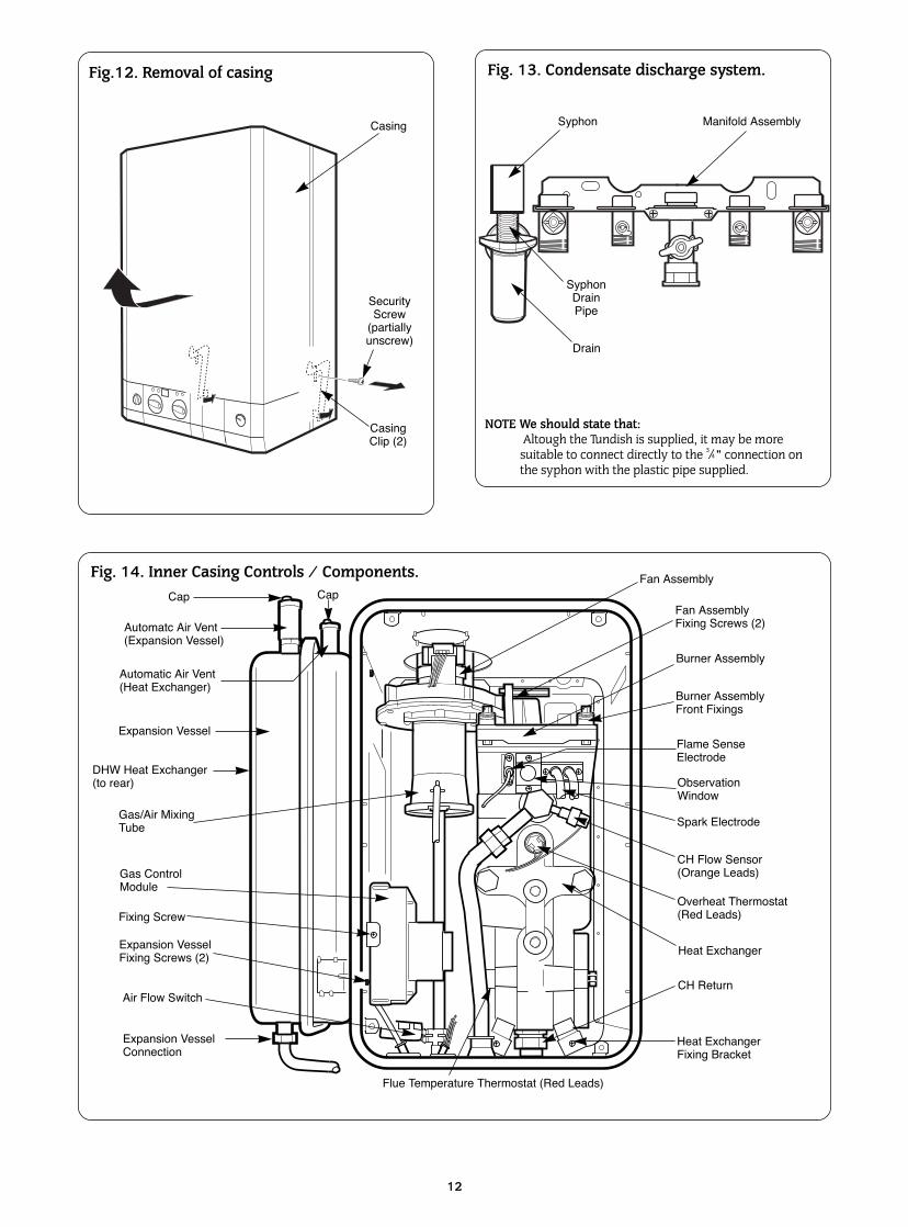
Fig. 13. Condensate discharge system.
Fig. 14. Inner Casing Controls / Components. Fan Assembly
Fan AssemblyFixing Screws (2)
Burner Assembly
Burner AssemblyFront Fixings
Flame SenseElectrode
ObservationWindow
Spark Electrode
CH Flow Sensor(Orange Leads)
Overheat Thermostat(Red Leads)
Heat Exchanger
CH Return
Flue Temperature Thermostat (Red Leads)
Air Flow Switch
Gas ControlModule
Gas/Air MixingTube
Expansion Vessel
Automatc Air Vent(Expansion Vessel)
Cap
Automatic Air Vent(Heat Exchanger)
Cap
Fig.12. Removal of casing
Casing
SecurityScrew
(partiallyunscrew)
CasingClip (2)
Syphon
SyphonDrainPipe
Drain
Manifold Assembly
Expansion VesselConnection
Expansion VesselFixing Screws (2)
DHW Heat Exchanger(to rear)
Fixing Screw
Heat ExchangerFixing Bracket
NOTE We should state that:Altough the Tundish is supplied, it may be more
suitable to connect directly to the 3/4 " connection on the syphon with the plastic pipe supplied.
1 2 4 7 8 9DC24V
1 2 3 4
1 2 4
1 2 4
TR...
13
12
3
4
CERAPUR:Diagram 10b26/3/99
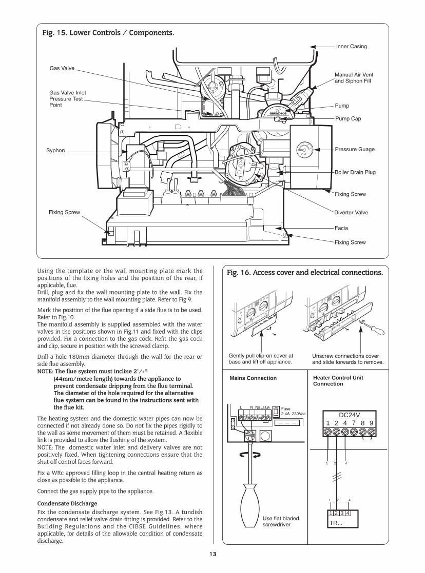
Fig. 15. Lower Controls / Components.
Gas Valve
Gas Valve InletPressure TestPoint
Syphon
Facia
Diverter Valve
Pressure Guage
Pump Cap
Pump
Manual Air Ventand Siphon Fill
Inner Casing
Fixing Screw
Fixing Screw
Using the template or the wall mounting plate mark thepositions of the fixing holes and the position of the rear, ifapplicable, flue.Drill, plug and fix the wall mounting plate to the wall. Fix themanifold assembly to the wall mounting plate. Refer to Fig.9.
Mark the position of the flue opening if a side flue is to be used.Refer to Fig.10. The manifold assembly is supplied assembled with the watervalves in the positions shown in Fig.11 and fixed with the clipsprovided. Fix a connection to the gas cock. Refit the gas cockand clip, secure in position with the screwed clamp.
Drill a hole 180mm diameter through the wall for the rear orside flue assembly. NOTE: The flue system must incline 21/2°
(44mm/metre length) towards the appliance to prevent condensate dripping from the flue terminal. The diameter of the hole required for the alternative flue system can be found in the instructions sent with the flue kit.
The heating system and the domestic water pipes can now beconnected if not already done so. Do not fix the pipes rigidly tothe wall as some movement of them must be retained. A flexiblelink is provided to allow the flushing of the system.NOTE: The domestic water inlet and delivery valves are notpositively fixed. When tightening connections ensure that theshut-off control faces forward.
Fix a WRc approved filling loop in the central heating return asclose as possible to the appliance.
Connect the gas supply pipe to the appliance.
Condensate DischargeFix the condensate discharge system. See Fig.13. A tundishcondensate and relief valve drain fitting is provided. Refer to theBuilding Regulations and the CIBSE Guidelines, whereapplicable, for details of the allowable condition of condensatedischarge.
0I
1
2
3
45
E
7
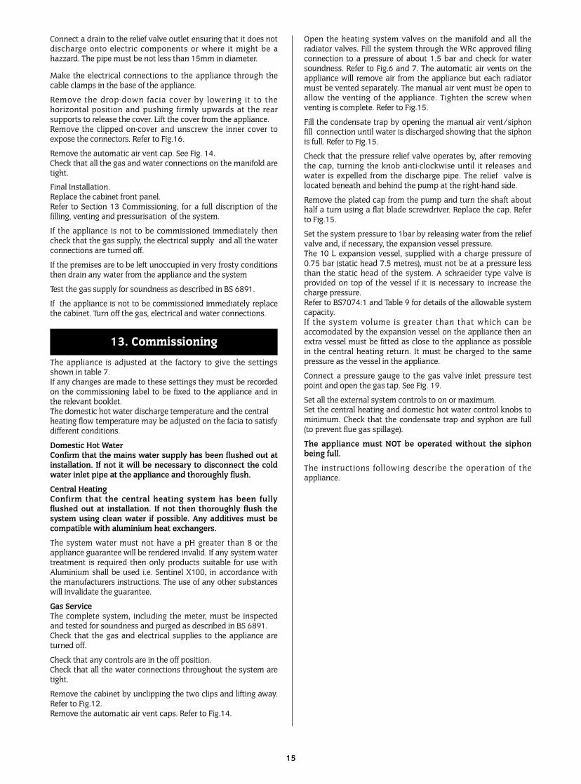
Fig. 16. Access cover and electrical connections.
+
0I
1
2
3
45
E
7
Gently pull clip-on cover atbase and lift off appliance.
Unscrew connections coverand slide forwards to remove.
Heater Control UnitConnection
Mains Connection
LRL N NsLs Fuse2.4A 230Vac
Use flat bladedscrewdriver
Boiler Drain Plug
Fixing Screw
A condensate neutralisation kit is available.The condensate drain pipe and fittings must be made of plastic(NO OTHER MATERIALS SHALL BE USED) with a minimumdiameter of 22mm.
The minimum fall for the drain pipe from the open tundish is2.5° (1 in 20). Where it is not practical to terminate a condensatedrain over a gully then an additional trap should be providedprior to any connection to a soil and vent pipe (discharge pipe) orwaste pipe (branch discharge pipe).
Any connection to a waste pipe should be downstream of theappliance trap to prevent any household waste blocking thecondensate drain or causing back flow or back pressure on theappliance.
Remove the security screw from the right-hand side of thecasing. Refer to Fig.12
Remove the cabinet by pressing both levers backwards to releaseand lift off the cabinet. See Fig.12.
Hang the appliance onto the wall.
Fit the fibre washers to the gas and water connections on themanifold.
Tighten the service connections.
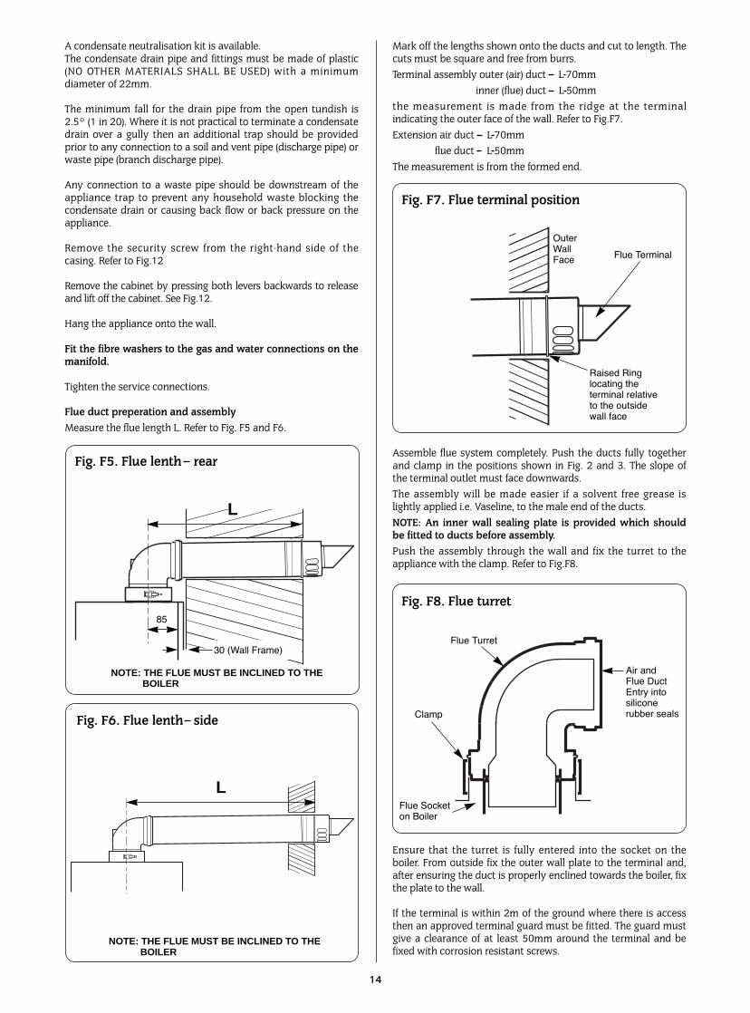
Flue duct preperation and assemblyMeasure the flue length L. Refer to Fig. F5 and F6.
Mark off the lengths shown onto the ducts and cut to length. Thecuts must be square and free from burrs.Terminal assembly outer (air) duct - L-70mm
inner (flue) duct - L-50mmthe measurement is made from the ridge at the terminalindicating the outer face of the wall. Refer to Fig.F7.Extension air duct - L-70mm
flue duct - L-50mmThe measurement is from the formed end.
Assemble flue system completely. Push the ducts fully togetherand clamp in the positions shown in Fig. 2 and 3. The slope ofthe terminal outlet must face downwards.The assembly will be made easier if a solvent free grease islightly applied i.e. Vaseline, to the male end of the ducts.NOTE: An inner wall sealing plate is provided which shouldbe fitted to ducts before assembly.Push the assembly through the wall and fix the turret to theappliance with the clamp. Refer to Fig.F8.
Ensure that the turret is fully entered into the socket on theboiler. From outside fix the outer wall plate to the terminal and,after ensuring the duct is properly enclined towards the boiler, fixthe plate to the wall.
If the terminal is within 2m of the ground where there is accessthen an approved terminal guard must be fitted. The guard mustgive a clearance of at least 50mm around the terminal and befixed with corrosion resistant screws.
14
NOTE: THE FLUE MUST BE INCLINED TO THE BOILER
L
85
Fig. F5. Flue lenth rear
NOTE: THE FLUE MUST BE INCLINED TO THE BOILER
L
Fig. F6. Flue lenth side
Fig. F7. Flue terminal position
OuterWallFace Flue Terminal
Raised Ringlocating theterminal relativeto the outsidewall face
Fig. F8. Flue turret
Air and Flue Duct Entry intosilicone rubber seals
Flue Turret
Clamp
Flue Socket on Boiler
30 (Wall Frame)
Connect a drain to the relief valve outlet ensuring that it does notdischarge onto electric components or where it might be ahazzard. The pipe must be not less than 15mm in diameter.
Make the electrical connections to the appliance through thecable clamps in the base of the appliance.
Remove the drop-down facia cover by lowering it to thehorizontal position and pushing firmly upwards at the rearsupports to release the cover. Lift the cover from the appliance.Remove the clipped on-cover and unscrew the inner cover toexpose the connectors. Refer to Fig.16.
Remove the automatic air vent cap. See Fig. 14. Check that all the gas and water connections on the manifold aretight.
Final Installation.Replace the cabinet front panel.Refer to Section 13 Commissioning, for a full discription of thefilling, venting and pressurisation of the system.
If the appliance is not to be commissioned immediately thencheck that the gas supply, the electrical supply and all the waterconnections are turned off.
If the premises are to be left unoccupied in very frosty conditionsthen drain any water from the appliance and the system
Test the gas supply for soundness as described in BS 6891.
If the appliance is not to be commissioned immediately replacethe cabinet. Turn off the gas, electrical and water connections.
The appliance is adjusted at the factory to give the settingsshown in table 7.If any changes are made to these settings they must be recordedon the commissioning label to be fixed to the appliance and inthe relevant booklet.The domestic hot water discharge temperature and the centralheating flow temperature may be adjusted on the facia to satisfydifferent conditions.
Domestic Hot WaterConfirm that the mains water supply has been flushed out atinstallation. If not it will be necessary to disconnect the coldwater inlet pipe at the appliance and thoroughly flush.
Central HeatingConfirm that the central heating system has been fullyflushed out at installation. If not then thoroughly flush thesystem using clean water if possible. Any additives must becompatible with aluminium heat exchangers.
The system water must not have a pH greater than 8 or theappliance guarantee will be rendered invalid. If any system watertreatment is required then only products suitable for use withAluminium shall be used i.e. Sentinel X100, in accordance withthe manufacturers instructions. The use of any other substanceswill invalidate the guarantee.
Gas ServiceThe complete system, including the meter, must be inspectedand tested for soundness and purged as described in BS 6891.Check that the gas and electrical supplies to the appliance areturned off.
Check that any controls are in the off position.Check that all the water connections throughout the system aretight.
Remove the cabinet by unclipping the two clips and lifting away.Refer to Fig.12.Remove the automatic air vent caps. Refer to Fig.14.
Open the heating system valves on the manifold and all theradiator valves. Fill the system through the WRc approved filingconnection to a pressure of about 1.5 bar and check for watersoundness. Refer to Fig.6 and 7. The automatic air vents on theappliance will remove air from the appliance but each radiatormust be vented separately. The manual air vent must be open toallow the venting of the appliance. Tighten the screw whenventing is complete. Refer to Fig.15.
Fill the condensate trap by opening the manual air vent/siphonfill connection until water is discharged showing that the siphonis full. Refer to Fig.15.
Check that the pressure relief valve operates by, after removingthe cap, turning the knob anti-clockwise until it releases andwater is expelled from the discharge pipe. The relief valve islocated beneath and behind the pump at the right-hand side.
Remove the plated cap from the pump and turn the shaft abouthalf a turn using a flat blade screwdriver. Replace the cap. Referto Fig.15.
Set the system pressure to 1bar by releasing water from the reliefvalve and, if necessary, the expansion vessel pressure.The 10 L expansion vessel, supplied with a charge pressure of0.75 bar (static head 7.5 metres), must not be at a pressure lessthan the static head of the system. A schraeider type valve isprovided on top of the vessel if it is necessary to increase thecharge pressure.Refer to BS7074:1 and Table 9 for details of the allowable systemcapacity.If the system volume is greater than that which can beaccomodated by the expansion vessel on the appliance then anextra vessel must be fitted as close to the appliance as possiblein the central heating return. It must be charged to the samepressure as the vessel in the appliance.
Connect a pressure gauge to the gas valve inlet pressure testpoint and open the gas tap. See Fig. 19.
Set all the external system controls to on or maximum. Set the central heating and domestic hot water control knobs tominimum. Check that the condensate trap and syphon are full(to prevent flue gas spillage).
The appliance must NOT be operated without the siphonbeing full.
The instructions following describe the operation of theappliance.
13. Commissioning
15
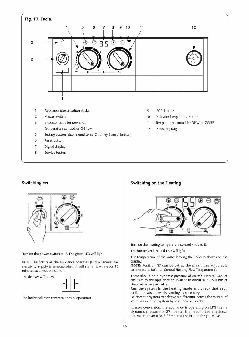
Fig. 17. Facia.
Switching on
Turn on the heating temperature control knob to E.
The burner and the red LED will light.
The temperature of the water leaving the boiler is shown on thedisplay.NOTE: Position 'E' can be set as the maximum adjustabletemperature. Refer to 'Central Heating Flow Temperature'.
There should be a dynamic pressure of 20 mb (Natural Gas) atthe inlet to the appliance equivalent to about 18.5-19.0 mb atthe inlet to the gas valve.Run the system in the heating mode and check that eachradiator heats up evenly, venting as necessary.Balance the system to achieve a differential across the system of20°c. An external system bypass may be needed.
If, after conversion, the appliance is operating on LPG then adynamic pressure of 37mbar at the inlet to the applianceequivalent to aout 34.5-35mbar at the inlet to the gas valve.
Turn on the power switch to 'I'. The green LED will light.
NOTE: The first time the appliance operates (and whenever theelectricity supply is re-established) it will run at low rate for 15minutes to check the siphon.
The display will show
The boiler will then revert to normal operation.
Switching on the Heating
16
1 Appliance identification sticker
2 Master switch
3 Indicator lamp for power on
4 Temperature control for CH flow
5 Setting button (also refered to as 'Chimney Sweep' button)
6 Reset button
7 Digital display
8 Service button
1
2
3
4 5 6 7 8 9 10 11 12
9 'ECO' button
10 Indicator lamp for burner on
11 Temperature control for DHW on ZWRB
12 Pressure guage
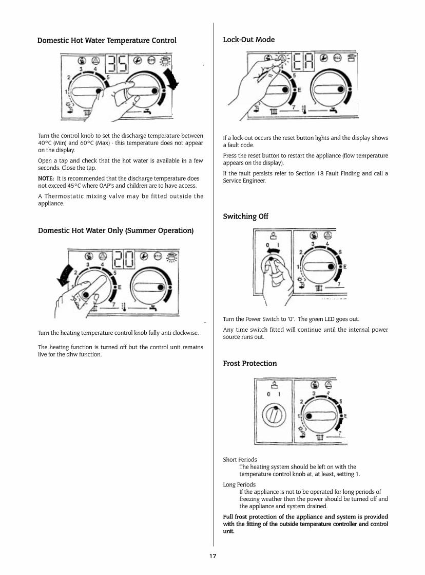
If a lock-out occurs the reset button lights and the display showsa fault code.
Press the reset button to restart the appliance (flow temperatureappears on the display).
If the fault persists refer to Section 18 Fault Finding and call aService Engineer.
Turn the Power Switch to '0'. The green LED goes out.
Any time switch fitted will continue until the internal powersource runs out.
Short PeriodsThe heating system should be left on with the temperature control knob at, at least, setting 1.
Long PeriodsIf the appliance is not to be operated for long periods of freezing weather then the power should be turned off andthe appliance and system drained.
Full frost protection of the appliance and system is providedwith the fitting of the outside temperature controller and controlunit.
17
Frost Protection
Turn the control knob to set the discharge temperature between40°C (Min) and 60°C (Max) - this temperature does not appearon the display.
Open a tap and check that the hot water is available in a fewseconds. Close the tap.
NOTE: It is recommended that the discharge temperature does not exceed 45°C where OAP's and children are to have access.
A Thermostatic mixing valve may be fitted outside theappliance.
Turn the heating temperature control knob fully anti-clockwise.
The heating function is turned off but the control unit remainslive for the dhw function.
Domestic Hot Water Temperature Control
Domestic Hot Water Only (Summer Operation)
Lock-Out Mode
Switching Off
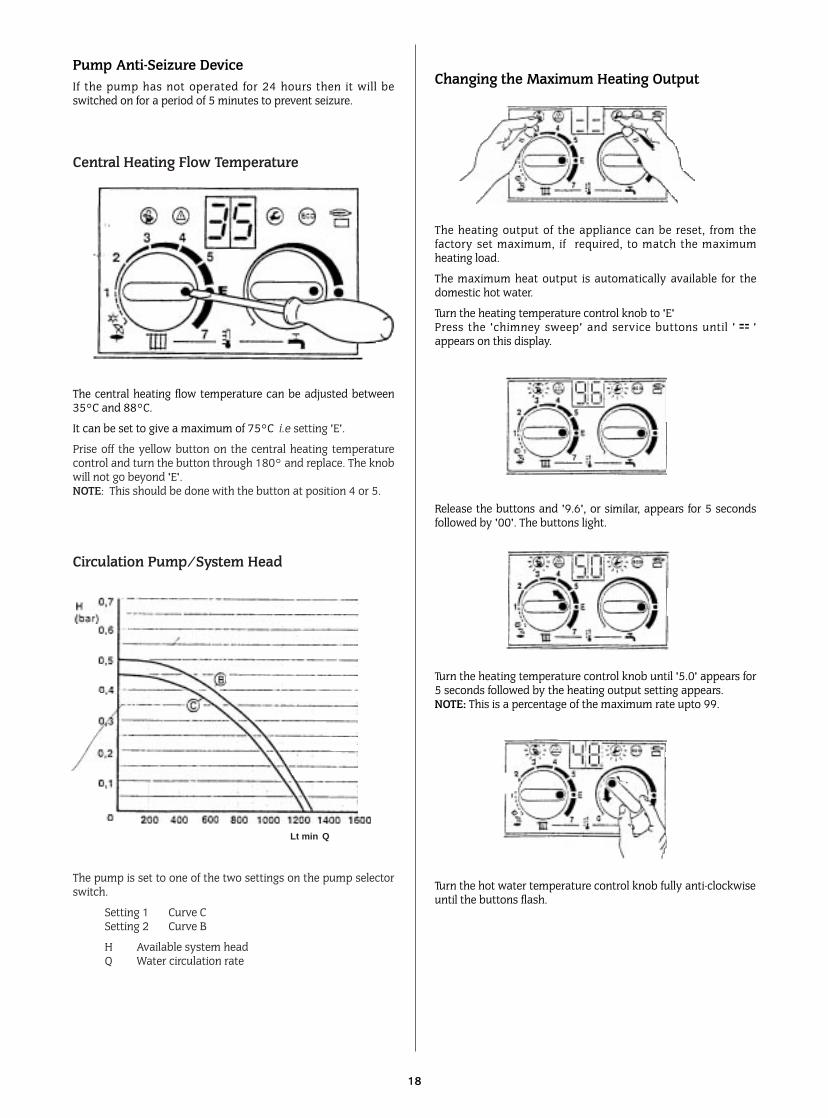
The heating output of the appliance can be reset, from thefactory set maximum, if required, to match the maximumheating load.
The maximum heat output is automatically available for thedomestic hot water.
Turn the heating temperature control knob to 'E'Press the 'chimney sweep' and service buttons until '='appears on this display.
Release the buttons and '9.6', or similar, appears for 5 secondsfollowed by '00'. The buttons light.
Turn the heating temperature control knob until '5.0' appears for5 seconds followed by the heating output setting appears.NOTE: This is a percentage of the maximum rate upto 99.
Turn the hot water temperature control knob fully anti-clockwiseuntil the buttons flash.
18
Changing the Maximum Heating OutputPump Anti-Seizure DeviceIf the pump has not operated for 24 hours then it will beswitched on for a period of 5 minutes to prevent seizure.
The central heating flow temperature can be adjusted between35°C and 88°C.
It can be set to give a maximum of 75°C i.e setting 'E'.
Prise off the yellow button on the central heating temperaturecontrol and turn the button through 180° and replace. The knobwill not go beyond 'E'.NOTE: This should be done with the button at position 4 or 5.
The pump is set to one of the two settings on the pump selectorswitch.
Setting 1 Curve CSetting 2 Curve B
H Available system headQ Water circulation rate
Central Heating Flow Temperature
Circulation Pump/System Head
Lt min Q
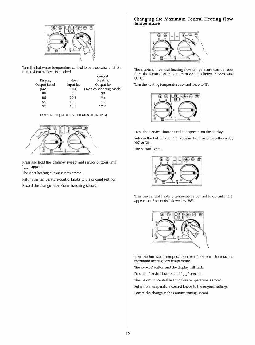
The maximum central heating flow temperature can be resetfrom the factory set maximum of 88°C to between 35°C and88°C .
Turn the heating temperature control knob to 'E'.
Press the 'service ' button until '--' appears on the display.
Release the button and '4.6' appears for 5 seconds followed by'00' or '01' .
The button lights.
Turn the central heating temperature control knob until '2.5'appears for 5 seconds followed by '88'.
Turn the hot water temperature control knob to the requiredmaximum heating flow temperature.
The 'service' button and the display will flash.
Press the 'service' button until ' ' appears.
The maximum central heating flow temperature is stored.
Return the temperature control knobs to the original settings.
Record the change in the Commissioning Record.
Turn the hot water temperature control knob clockwise until therequired output level is reached.
Display Heat HeatingOutput Level Input kw Output kw
(MAX) (NET) ( Non-condensing Mode)99 24 2385 20.6 19.665 15.8 1555 13.5 12.7
NOTE: Net Input = 0.901 x Gross Input (NG)
Press and hold the 'chimney sweep' and service buttons until ' ' appears.
The reset heating output is now stored.
Return the temperature control knobs to the original settings.
Record the change in the Commissioning Record.
19
Changing the Maximum Central Heating FlowTemperature
Central
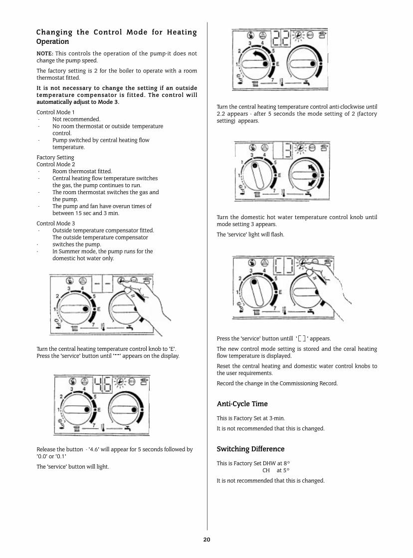
NOTE: This controls the operation of the pump-it does notchange the pump speed.
The factory setting is 2 for the boiler to operate with a roomthermostat fitted.
It is not necessary to change the setting if an outsidetemperature compensator is f itted. The control wil lautomatically adjust to Mode 3.
Control Mode 1 - Not recommended.- No room thermostat or outside temperature
control.- Pump switched by central heating flow
temperature.
Factory SettingControl Mode 2 - Room thermostat fitted.- Central heating flow temperature switches
the gas, the pump continues to run.- The room thermostat switches the gas and
the pump.- The pump and fan have overun times of
between 15 sec and 3 min.
Control Mode 3 - Outside temperature compensator fitted.
The outside temperature compensator - switches the pump.- In Summer mode, the pump runs for the
domestic hot water only.
Turn the central heating temperature control knob to 'E'.Press the 'service' button until '--' appears on the display.
Release the button - '4.6' will appear for 5 seconds followed by'0.0' or '0.1'
The 'service' button will light.
20
Changing the Control Mode for HeatingOperation
Turn the central heating temperature control anti-clockwise until2.2 appears - after 5 seconds the mode setting of 2 (factorysetting) appears.
Turn the domestic hot water temperature control knob untilmode setting 3 appears.
The 'service' light will flash.
Press the 'service' button untill ' ' appears.
The new control mode setting is stored and the ceral heatingflow temperature is displayed.
Reset the central heating and domestic water control knobs tothe user requirements.
Record the change in the Commissioning Record.
Anti-Cycle Time
This is Factory Set at 3-min.
It is not recommended that this is changed.
Switching Difference
This is Factory Set DHW at 8° CH at 5°
It is not recommended that this is changed.
Completion of CommissioningNote: Operating with a lower heating flow temperature willresult in the appliance operating in the much more efficientcondensing mode. To ensure that the rooms are properly heatedthe radiators must be sized accordingly.
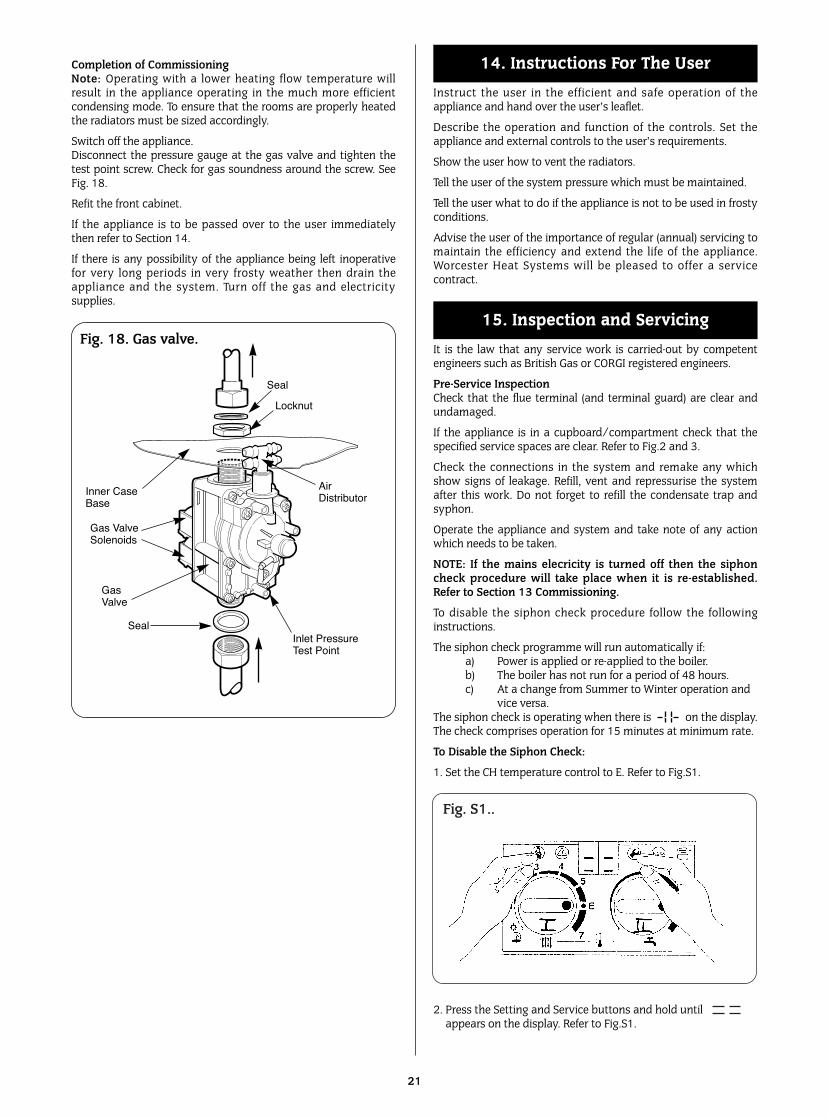
Switch off the appliance.Disconnect the pressure gauge at the gas valve and tighten thetest point screw. Check for gas soundness around the screw. SeeFig. 18.
Refit the front cabinet.
If the appliance is to be passed over to the user immediatelythen refer to Section 14.
If there is any possibility of the appliance being left inoperativefor very long periods in very frosty weather then drain theappliance and the system. Turn off the gas and electricitysupplies.
Instruct the user in the efficient and safe operation of theappliance and hand over the user’s leaflet.
Describe the operation and function of the controls. Set theappliance and external controls to the user’s requirements.
Show the user how to vent the radiators.
Tell the user of the system pressure which must be maintained.
Tell the user what to do if the appliance is not to be used in frostyconditions.
Advise the user of the importance of regular (annual) servicing tomaintain the efficiency and extend the life of the appliance.Worcester Heat Systems will be pleased to offer a servicecontract.
It is the law that any service work is carried-out by competentengineers such as British Gas or CORGI registered engineers.
Pre-Service InspectionCheck that the flue terminal (and terminal guard) are clear andundamaged.
If the appliance is in a cupboard/compartment check that thespecified service spaces are clear. Refer to Fig.2 and 3.
Check the connections in the system and remake any whichshow signs of leakage. Refill, vent and repressurise the systemafter this work. Do not forget to refill the condensate trap andsyphon.
Operate the appliance and system and take note of any actionwhich needs to be taken.
NOTE: If the mains elecricity is turned off then the siphoncheck procedure will take place when it is re-established.Refer to Section 13 Commissioning.
To disable the siphon check procedure follow the followinginstructions.
The siphon check programme will run automatically if:a) Power is applied or re-applied to the boiler.b) The boiler has not run for a period of 48 hours.c) At a change from Summer to Winter operation and
vice versa.The siphon check is operating when there is on the display.The check comprises operation for 15 minutes at minimum rate.
To Disable the Siphon Check:
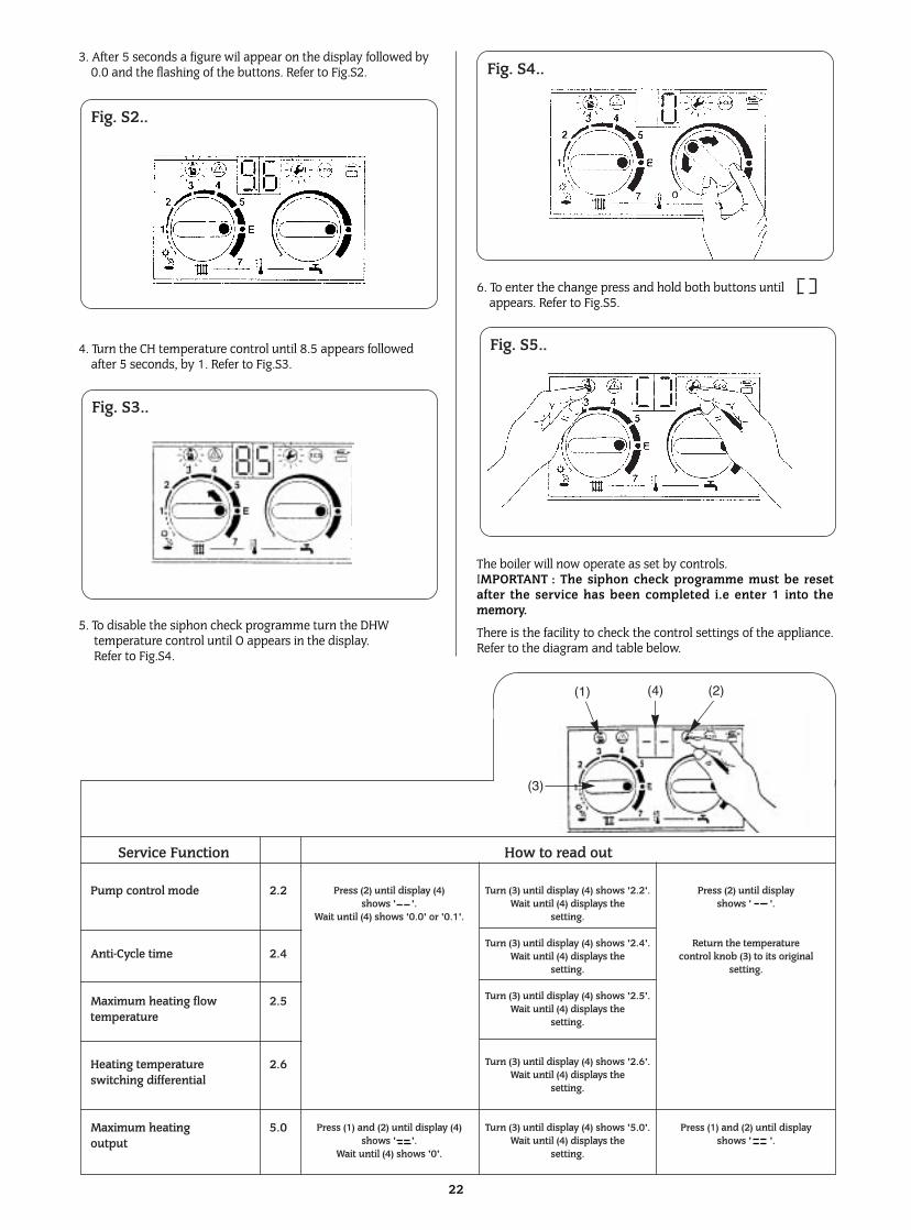
1. Set the CH temperature control to E. Refer to Fig.S1.
2. Press the Setting and Service buttons and hold until appears on the display. Refer to Fig.S1.
15. Inspection and Servicing
14. Instructions For The User
21
Fig. 18. Gas valve.
Inlet Pressure Test Point
Seal
Locknut
Air Distributor
Seal
Gas Valve
Gas Valve Solenoids
Inner CaseBase
Fig. S1..
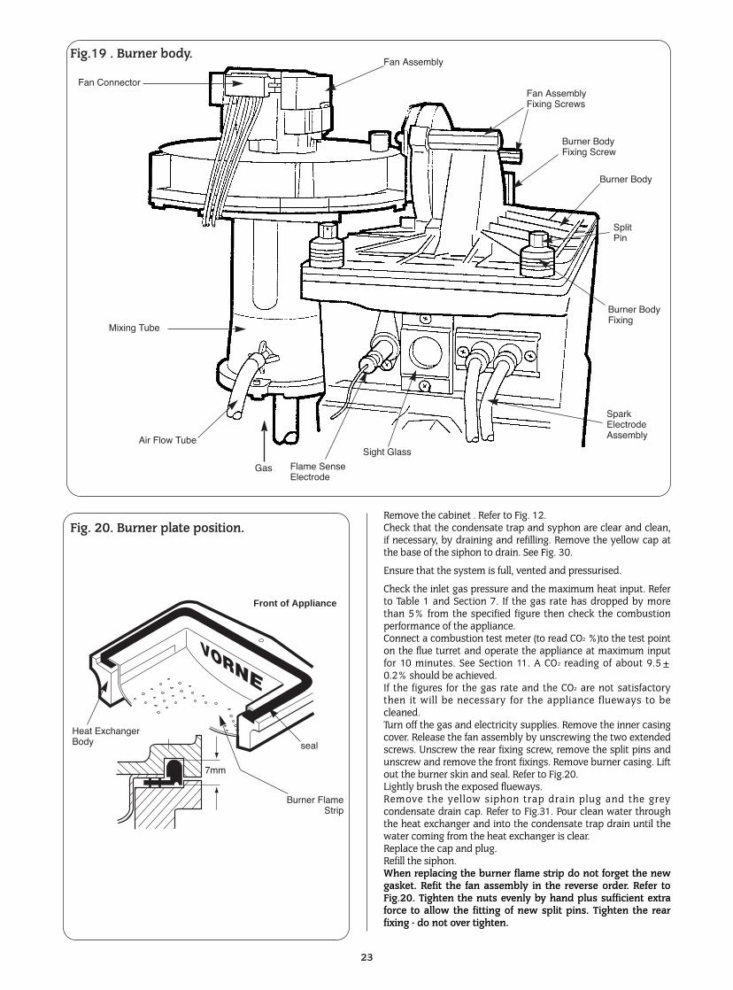
3. After 5 seconds a figure wil appear on the display followed by 0.0 and the flashing of the buttons. Refer to Fig.S2.
4. Turn the CH temperature control until 8.5 appears followed after 5 seconds, by 1. Refer to Fig.S3.
5. To disable the siphon check programme turn the DHWtemperature control until O appears in the display. Refer to Fig.S4.
6. To enter the change press and hold both buttons until appears. Refer to Fig.S5.
The boiler will now operate as set by controls.IMPORTANT : The siphon check programme must be resetafter the service has been completed i.e enter 1 into thememory.
There is the facility to check the control settings of the appliance.Refer to the diagram and table below.
22
Fig. S2..
Fig. S3..
Service Function How to read out
Pump control mode 2.2
Anti-Cycle time 2.4
Maximum heating flow 2.5 temperature
Heating temperature 2.6 switching differential
Maximum heating 5.0 output
Press (2) until display (4) shows ' '.
Wait until (4) shows '0.0' or '0.1'.
Press (1) and (2) until display (4) shows ' '.
Wait until (4) shows '0'.
Turn (3) until display (4) shows '2.2'.Wait until (4) displays the
setting.
Turn (3) until display (4) shows '2.4'.Wait until (4) displays the
setting.
Turn (3) until display (4) shows '2.5'.Wait until (4) displays the
setting.
Turn (3) until display (4) shows '2.6'.Wait until (4) displays the
setting.
Turn (3) until display (4) shows '5.0'.Wait until (4) displays the
setting.
Press (2) until display shows ' '.
Return the temperature control knob (3) to its original
setting.
Press (1) and (2) until display shows ' '.
(1) (4) (2)
(3)
Fig. S4..
Fig. S5..
Remove the cabinet . Refer to Fig. 12.Check that the condensate trap and syphon are clear and clean,if necessary, by draining and refilling. Remove the yellow cap atthe base of the siphon to drain. See Fig. 30.
Ensure that the system is full, vented and pressurised.
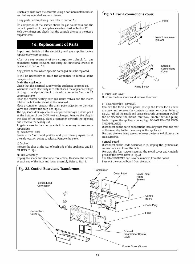
Check the inlet gas pressure and the maximum heat input. Referto Table 1 and Section 7. If the gas rate has dropped by morethan 5% from the specified figure then check the combustionperformance of the appliance.Connect a combustion test meter (to read CO2 %)to the test pointon the flue turret and operate the appliance at maximum inputfor 10 minutes. See Section 11. A CO2 reading of about 9.5±0.2% should be achieved.If the figures for the gas rate and the CO2 are not satisfactorythen it will be necessary for the appliance flueways to becleaned.Turn off the gas and electricity supplies. Remove the inner casingcover. Release the fan assembly by unscrewing the two extendedscrews. Unscrew the rear fixing screw, remove the split pins andunscrew and remove the front fixings. Remove burner casing. Liftout the burner skin and seal. Refer to Fig.20.Lightly brush the exposed flueways.Remove the yellow siphon trap drain plug and the greycondensate drain cap. Refer to Fig.31. Pour clean water throughthe heat exchanger and into the condensate trap drain until thewater coming from the heat exchanger is clear.Replace the cap and plug.Refill the siphon.When replacing the burner flame strip do not forget the newgasket. Refit the fan assembly in the reverse order. Refer toFig.20. Tighten the nuts evenly by hand plus sufficient extraforce to allow the fitting of new split pins. Tighten the rearfixing - do not over tighten.
23
Fig.19 . Burner body.Fan Assembly
Fan AssemblyFixing Screws
Burner Body Fixing Screw
Burner Body
SplitPin
Burner Body Fixing
Spark ElectrodeAssembly
Sight Glass
Flame SenseElectrode
Fig. 20. Burner plate position.
Air Flow Tube
Gas
Mixing Tube
Fan Connector
Front of Appliance
seal
Burner FlameStrip
7mm
Heat ExchangerBody
24
Brush any dust from the controls using a soft non-metallic brushand battery operated vacuum cleaner.
If any parts need replacing then refer to Section 16.
On completion of the service check for gas soundness and thecorrect operation of the appliance as described in Section 12.Refit the cabinet and check that the controls are set to the user’srequirements.
Important: Switch off the electricity and gas supplies beforereplacing any components.
After the replacement of any component check for gassoundness, where relevant, and carry out functional checks asdescribed in Section 13.
Any gasket or seal which appears damaged must be replaced.
It will be necessary to drain the appliance to remove somecomponents.Drain the ApplianceCheck that the electrical supply to the appliance is turned off.When the mains electricity is re-established the appliance will gothrough the siphon check procedure. refer to Section 13commissioning.Close the central heating flow and return valves and the mainsinlet to the hot water circuit at the manifold.Place a container beneath the drain point adjacent to the reliefvalve and unsrew the plug. See Fig.15.The appliance drainage can be completed through a drain pointat the bottom of the DHW heat exchanger. Remove the plug inthe base of the casing, place a container beneath the openingand unscrew the sealing nut.To gain access to the components it is necessary to remove orreposition :a) Facia Cover PanelLower to the 'horizontal' position and push firmly upwards atthe side location points to release. Remove the panel.
b) CabinetRelease the clips at the rear of each side of the appliance and liftoff. Refer to Fig.9.
c) Facia AssemblyUnplug the spark and electrode connection. Unscrew the screwsat each end of the facia and lower assembly. Refer to Fig.15.
d) Inner Case CoverUnscrew the four screws and remove the cover.
e) Facia Assembly - Removal.Remove the facia cover panel. Unclip the lower facia cover,unscrew and remove the controls connection cover. Refer toFig.20. Pull off the spark and sense electrode connection. Pull offthe or disconect the mains, multiway, fan/burner and pumpleads. Unplug the appliance code plug - DO NOT REMOVE FROMTHE APPLIANCE. Disconnect all the earth connections including that from the rearof the assembly to the main body of the appliance.Unscrew the two fixing screws to lower the facia and lift from theside supports.
Control BoardDisconnect all the leads described in (e). Unplug the ignition leadconnections and lower the facia.Unscrew the four screws securing the metal cover and carefullyprise off the cover. Refer to Fig.22.The TRANSFORMER can now be removed from the board.Ease out the control board from the facia.
16. Replacement of Parts
0I
1
2
3
45
E
7
0I
1
2
3
45
E
7
Fig. 21. Facia connections cover.
CERAPUR:Diagram 826/3/99
TransformerCover Plate Cover Plate
FixingScrews
ControlBoard
Facia
ExternalProgrammer ControlCover
Control Cover (Spare)
Ignition LeadConnection
ConnectionsCover
Fig. 22. Control Board and Transformer.
Facia
Lower Facia cover(clip-on)
ControlsConnections Cover
Fixing Screw
Code Plug
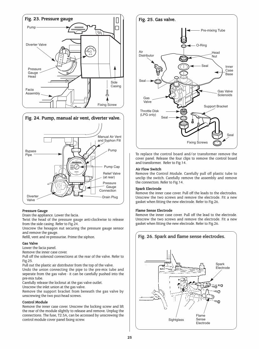
Pressure GaugeDrain the appliance. Lower the facia.Twist the head of the pressure gauge anti-clockwise to releasefrom the side casing. Refer to Fig.24.Unscrew the hexagon nut securing the pressure gauge sensorand remove the gauge.Refill, vent and re-pressurise. Prime the siphon.
Gas ValveLower the facia panel.Remove the inner case cover.Pull off the solenoid connections at the rear of the valve. Refer toFig.25.Pull out the plastic air distributer from the top of the valve.Undo the union connecting the pipe to the pre-mix tube andseperate from the gas valve - it can be carefully pushed into thepre-mix tube.Carefully release the locknut at the gas valve outlet.Unscrew the inlet union at the gas valve.Remove the support bracket from beneath the gas valve byunscrewing the two pozi-head screws.
Control ModuleRemove the inner case cover. Unscrew the locking screw and liftthe rear of the module slightly to release and remove. Unplug theconnections. The fuse, T2.5A, can be accessed by unscrewing thecontrol module cover panel fixing screw.
To replace the control board and/or transformer remove thecover panel. Release the four clips to remove the control boardand transformer. Refer to Fig.14.
Air Flow SwitchRemove the Control Module. Carefully pull off plastic tube tounclip the switch. Carefully remove the assembly and removethe connectors. Refer to Fig.14.
Spark ElectrodeRemove the inner case cover. Pull off the leads to the electrodes.Unscrew the two screws and remove the electrode. Fit a newgasket when fitting the new electrode. Refer to Fig.26.
Flame Sense ElectrodeRemove the inner case cover. Pull off the lead to the electrode.Unscrew the two screws and remove the electrode. Fit a newgasket when fitting the new electrode. Refer to Fig.26.
25
12
3
4
Fig. 23. Pressure gauge
Fig. 24. Pump, manual air vent, diverter valve.
Fig. 25. Gas valve.
Fig. 26. Spark and flame sense electrodes.
Pump
Diverter Valve
Pressure Gauge Head
FaciaAssembly
SideCasing
Fixing Screw
Manual Air Ventand Syphon Fill
Pump
Pump Cap
Pressure Gauge
Connection
Drain PlugDiverter Valve
BypassPipe
Seal
Fixing Screws
Support Bracket
Seal
Seal
Seal
Gas ValveSolenoids
Inner CaseBase
Throttle Disk(LPG only)
GasValve
AirDistributor
HeadNut
O-Ring
Pre-mixing Tube
Spark Electrode
FlameSenseElectrode
Sightglass
Relief Valve(at rear)
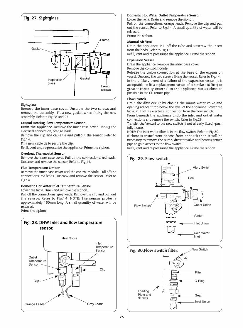
SightglassRemove the inner case cover. Unscrew the two screws andremove the assembly. Fit a new gasket when fitting the newassembly. Refer to Fig.26 and 27.
Central Heating Flow Temperature SensorDrain the appliance. Remove the inner case cover. Unplug theelectrical connection, orange leads. Remove the clip and cable tie and pull-out the sensor. Refer toFig.14. Fit a new cable tie to secure the clip.Refill, vent and re-pressurise the appliance. Prime the siphon.
Overheat Thermostat Sensor Remove the inner case cover. Pull off the connections, red leads.Unscrew and remove the sensor. Refer to Fig.14.
Flue Temperature Limiter Remove the inner case cover and the control module. Pull off theconnections, red leads. Unscrew and remove the sensor. Refer toFig.14.
Domestic Hot Water Inlet Temperature SensorLower the facia. Drain and remove the siphon.Pull off the connections, grey leads. Remove the clip and pull outthe sensor. Refer to Fig.14. NOTE: The sensor probe isapproximately 150mm long. A small quantity of water will bereleased.Prime the siphon.
Domestic Hot Water Outlet Temperature SensorLower the facia. Drain and remove the siphon.Pull off the connections, orange leads. Remove the clip and pullout the sensor. Refer to Fig.14. A small quantity of water will bereleased.Prime the siphon.
Manual Air VentDrain the appliance. Pull off the tube and unscrew the insertfrom the body. Refer to Fig.15.Refill, vent and re-pressurise the appliance. Prime the siphon.
Expansion VesselDrain the appliance. Remove the inner case cover. Remove the control module.Release the union connection at the base of the expansionvessel. Unscrew the two screws fixing the vessel. Refer to Fig.14.In the unlikely event of a failure of the expansion vessel, it isacceptable to fit a replacement vessel of a similar (10 litre) orgreater capacity external to the appliance but as close aspossible in the CH return pipe.
Flow SwitchDrain the dhw circuit by closing the mains water valve andopening adjacent tap below the level of the appliance. Lower thefacia. Pull off the electrical connection from the flow switch.From beneath the appliance undo the inlet and outlet waterconnections and remove the switch. Refer to Fig.29.Transfer the Venturi to the new switch (if not already fitted) -pushfully home.NOTE: The inlet water filter is in the flow switch. Refer to Fig.30.If there is insufficient access from beneath then it will benecessary to remove the pump, diverter valve and heating returnpipe to gain access to the flow switch.Refill, vent and re-pressurise the appliance. Prime the siphon.
26
Fig. 27. Sightglass.
Inspectionglass
Fixingscrews
Gasket
Gasket
Frame
Fig. 28. DHW Inlet and flow temperature sensor.
Heat Store
OutletTemperatureSensor
InletTemperatureSensor
Clip
Grey LeadsOrange Leads
Clip
Fig. 29. Flow switch.
Fig. 30.Flow switch filter.
Micro Switch
Seal
Outlet Union
Inlet Union
Cold WaterInlet
Flow Switch
Flow Switch
Filter
O-Ring
Seal
Inlet Union
LoadingPlate andScrews
Venturi
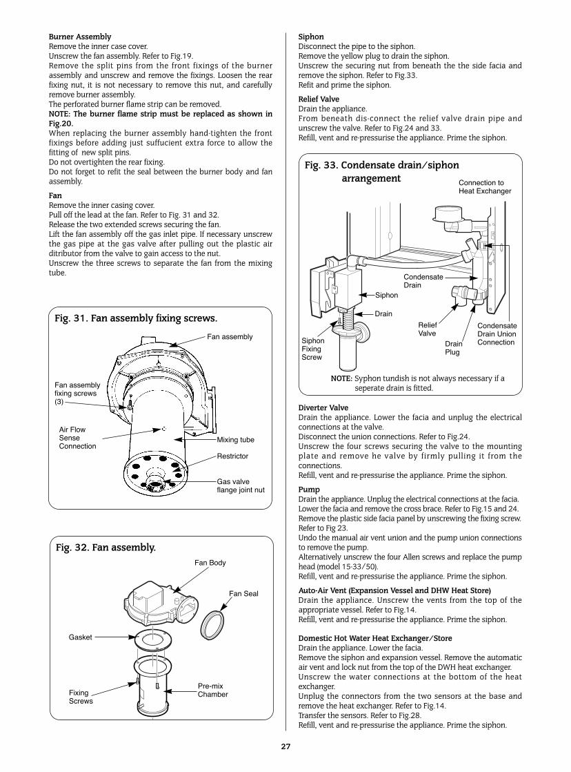
Burner Assembly Remove the inner case cover.Unscrew the fan assembly. Refer to Fig.19.Remove the split pins from the front fixings of the burnerassembly and unscrew and remove the fixings. Loosen the rearfixing nut, it is not necessary to remove this nut, and carefullyremove burner assembly. The perforated burner flame strip can be removed. NOTE: The burner flame strip must be replaced as shown inFig.20.When replacing the burner assembly hand-tighten the frontfixings before adding just suffucient extra force to allow thefitting of new split pins.Do not overtighten the rear fixing.Do not forget to refit the seal between the burner body and fanassembly.
FanRemove the inner casing cover.Pull off the lead at the fan. Refer to Fig. 31 and 32. Release the two extended screws securing the fan. Lift the fan assembly off the gas inlet pipe. If necessary unscrewthe gas pipe at the gas valve after pulling out the plastic airditributor from the valve to gain access to the nut.Unscrew the three screws to separate the fan from the mixingtube.
SiphonDisconnect the pipe to the siphon. Remove the yellow plug to drain the siphon. Unscrew the securing nut from beneath the the side facia andremove the siphon. Refer to Fig.33.Refit and prime the siphon.
Relief ValveDrain the appliance.From beneath dis-connect the relief valve drain pipe andunscrew the valve. Refer to Fig.24 and 33.Refill, vent and re-pressurise the appliance. Prime the siphon.
Diverter ValveDrain the appliance. Lower the facia and unplug the electricalconnections at the valve.Disconnect the union connections. Refer to Fig.24.Unscrew the four screws securing the valve to the mountingplate and remove he valve by firmly pulling it from theconnections.Refill, vent and re-pressurise the appliance. Prime the siphon.
PumpDrain the appliance. Unplug the electrical connections at the facia. Lower the facia and remove the cross brace. Refer to Fig.15 and 24.Remove the plastic side facia panel by unscrewing the fixing screw.Refer to Fig 23.Undo the manual air vent union and the pump union connectionsto remove the pump.Alternatively unscrew the four Allen screws and replace the pumphead (model 15-33/50).Refill, vent and re-pressurise the appliance. Prime the siphon.
Auto-Air Vent (Expansion Vessel and DHW Heat Store) Drain the appliance. Unscrew the vents from the top of theappropriate vessel. Refer to Fig.14. Refill, vent and re-pressurise the appliance. Prime the siphon.
Domestic Hot Water Heat Exchanger/Store Drain the appliance. Lower the facia. Remove the siphon and expansion vessel. Remove the automaticair vent and lock nut from the top of the DWH heat exchanger. Unscrew the water connections at the bottom of the heatexchanger.Unplug the connectors from the two sensors at the base andremove the heat exchanger. Refer to Fig.14.Transfer the sensors. Refer to Fig.28.Refill, vent and re-pressurise the appliance. Prime the siphon.
27
Fig. 33. Condensate drain/siphon arrangement
Fig. 32. Fan assembly.
Fig. 31. Fan assembly fixing screws.
Gas valveflange joint nut
Restrictor
Mixing tubeAir FlowSenseConnection
Fan assemblyfixing screws(3)
Fan assembly
Connection to Heat Exchanger
CondensateDrain UnionConnectionDrain
Plug
ReliefValve
CondensateDrain
Drain
Siphon
SiphonFixingScrew
Fan Body
Fan Seal
Pre-mixChamberFixing
Screws
Gasket
NOTE: Syphon tundish is not always necessary if a seperate drain is fitted.
Primary Heat Exchanger Refer to Figs. 14,15 and 33.Drain the appliance. Lower the facia and remove the inner casingcover.Remove the control module, the air flow switch and the plasticair distributor from the gas valve.Disconnect and remove the sensors and the flue thermostat fromthe bottom left-hand side of the heat exchanger.Disconnect and remove the hot water flow pipe from the front ofthe heat exchanger.Remove the gas supply pipe to the fan.Release the clip at the base of the flue duct by unscrewing thesingle screw and push the duct upwards to release it from theelbow at the base of the heat exchanger.To increase the access remove the pump completely and removethe pipe connection to the expansion vessel.Unscrew the hexagon head screw on the outside of the rearright-hand side of the cabinet and remove the condensate drainbracket.Unscrew the plastic nut securing the top of the condensate drainat the rear of the pump and put the drain assembly to one sidereleasing its connection to the condensate collector at the baseof the heat exchanger.Pull out the condensate collector from the base of the heatexchanger.Unscrew the two screws at the top securing the heat exchangerbacking plate to the top of the inner case back panel.The heat exchanger can now be pulled forward and removedfrom the appliance with the fan and burner assembly. Take care,as some water will remain in the heat exchanger.
Transfer the relevant components to the new heat exchanger andfit to the appliance in the reverse order. Important: Fit the circular rubber seal to the base of the heatexchanger AFTER the heat exchanger has been refitted to theappliance. Use new gaskets or seals where any appear damaged.Ensure that the flue duct is correctly connected. Refill, vent and re-pressurise the system. Check for the correct operation of the appliance by following theCommissioning procedure described in section 13.
28
29
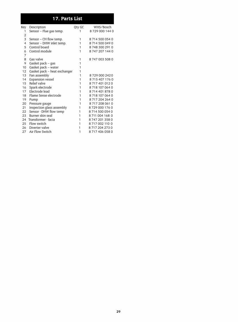
Key Description Qty GC WHS/Bosch1 Sensor – Flue gas temp. 1 8 729 000 144 023 Sensor – CH flow temp. 1 8 714 500 054 04 Sensor – DHW inlet temp. 1 8 714 500 049 05 Control board 1 8 748 300 291 06 Control module 1 8 747 207 144 078 Gas valve 1 8 747 003 508 09 Gasket pack – gas 1
10 Gasket pack – water 112 Gasket pack – heat exchanger 113 Fan assembly 1 8 729 000 242014 Expansion vessel 1 8 715 407 176 015 Relief valve 1 8 717 401 012 016 Spark electrode 1 8 718 107 064 017 Electrode lead 1 8 714 401 878 018 Flame Sense electrode 1 8 718 107 064 019 Pump 1 8 717 204 264 020 Pressure gauge 1 8 717 208 061 021 Inspection glass assembly 1 8 729 000 176 022 Sensor - DHW flow temp 1 8 714 500 054 023 Burner skin seal 1 8 711 004 168 024 Transformer - facia 1 8 747 201 358 025 Flow switch 1 8 717 002 110 026 Diverter valve 1 8 717 204 273 027 Air Flow Switch 1 8 717 406 058 0
17. Parts List
30
Pum
p O
N.
Fan
to m
axim
umsp
eed.
Div
erte
r va
lve
oper
ates
.
10 s
ec.
wai
t.
Gree
nlig
ht
ON
.
Burn
er s
hut-d
own
ifpr
imar
y te
mpe
ratu
re94
°C.
Rem
ains
off
until
te
mpe
ratu
re is
78°
C.
Air
pre
ssur
e ch
eck.
DO
MES
TIC
HOT
WAT
ER F
UN
CTIO
N
Fan
to s
tart
spee
d.A
ir p
ress
ure
switc
h cl
oses
.Ga
s va
lve
open
s.
Igni
tion
sequ
ence
Igni
tion
Spar
k 5
sec.
Burn
er li
ghts
.Re
d lig
ht O
N.
Hea
t sto
re s
atis
fied
Ove
r te
mpe
ratu
resh
ut-d
own
if w
ater
tem
pera
ture
is 8
°Cab
ove
set v
alue
.
Gas
valv
e sh
uts.
Ligh
t rem
ains
ON
.Pu
mp
rem
ains
ON
.
Mai
nssw
itch
ON
.
Hot
wat
erde
man
d.Pr
e-he
atm
ode
**.
Air
pr
essu
resw
itch
chec
k.
Fan
to s
tart
spee
d.A
ir p
ress
ure
switc
h cl
oses
.Ga
s va
lve
open
s.
Hea
t im
put
mod
ulat
es to
mai
ntai
n th
ede
liver
y te
mpe
ratu
re.
Dem
and
ends
.
Hea
t sto
re re
char
ge**
Gas
valv
e sh
uts.
Burn
er li
ght
OFF
.
Fan
runs
for
upto
3
min
utes
.D
iver
ter
valv
ecl
oses
.Pu
mp
runs
for
3.5
min
utes
.
Igni
tion
spar
k fo
r 5
sec.
Burn
er li
ghts
.Re
d lig
ht O
N.
Igni
tion
sequ
ence
Yes
No
Fan
runs
to p
urge
ga
s fr
om b
urne
r.
Repe
ats
5 tim
esbe
fore
lock
-out
.
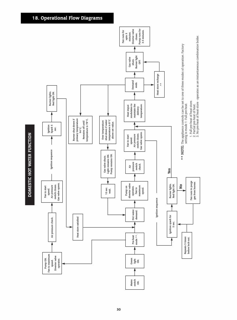
** N
OTE
:The
app
lianc
e co
ntro
ls c
an b
e se
t to
one
of th
ree
mod
es o
f ope
ratio
n. F
acto
ry
sett
ing
is m
ode
1- F
ull p
re-h
eat.
1. F
ull p
re-h
eat o
f hea
t-sto
re.
2. P
artia
l pre
-hea
t of h
eat.
3. N
o pr
e-he
at o
f hea
t-sto
re -
oper
ates
as
an in
stan
tane
ous
com
bina
tion
boile
r.
Pum
p on
dive
rter
val
veop
erat
es.
Fan
to
max
imum
spee
d.
18. Operational Flow Diagrams
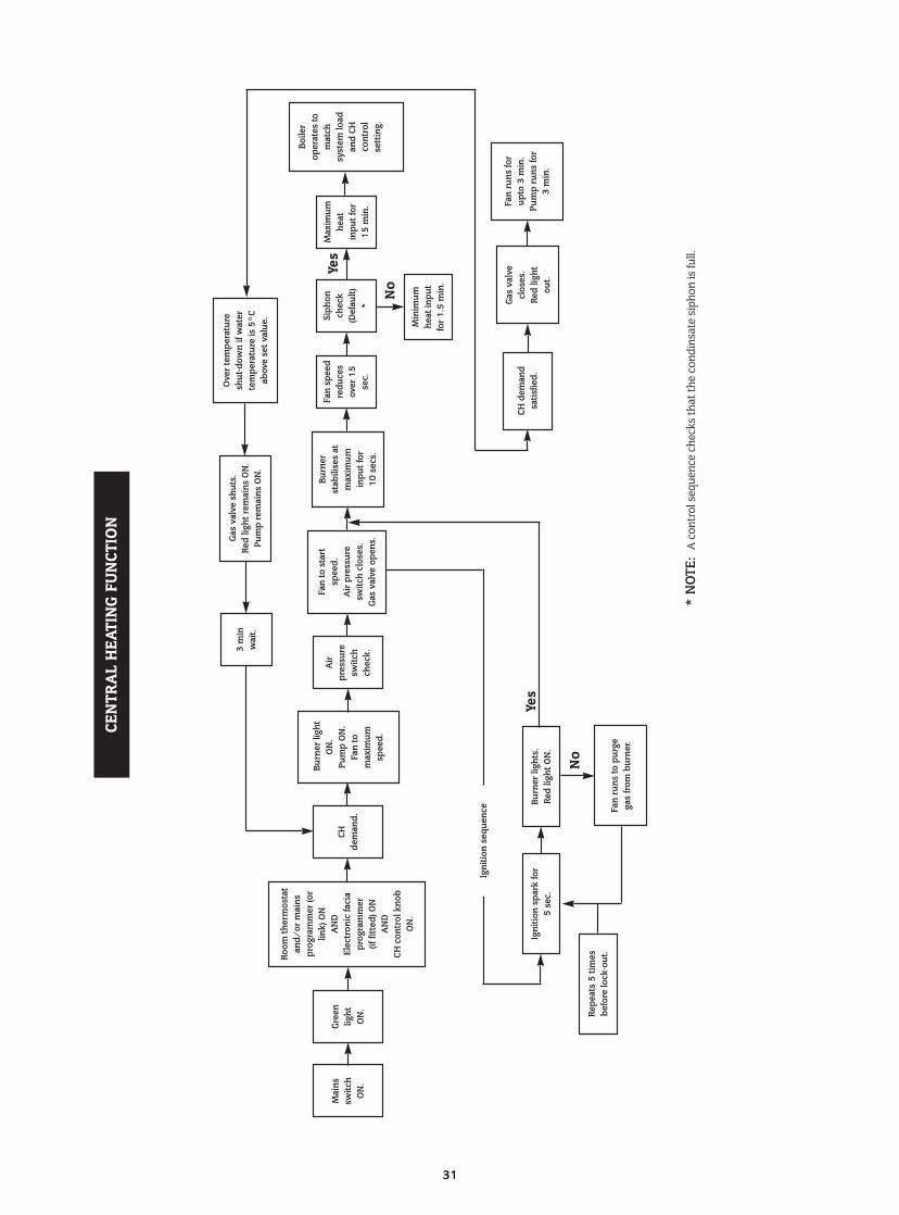
31
Burn
er li
ght
ON
.Pu
mp
ON
.Fa
n to
m
axim
umsp
eed.
3 m
inw
ait.
Gree
nlig
ht
ON
.
Room
ther
mos
tat
and/
or m
ains
prog
ram
mer
(or
link)
ON
AN
DEl
ectr
onic
faci
apr
ogra
mm
er
(if fi
tted
) ON
AN
DCH
con
trol
kno
bO
N.
CEN
TRA
L H
EATI
NG
FUN
CTIO
N
Ove
r te
mpe
ratu
resh
ut-d
own
if w
ater
tem
pera
ture
is 5
°Cab
ove
set v
alue
.
Gas
valv
e sh
uts.
Red
light
rem
ains
ON
.Pu
mp
rem
ains
ON
.
Mai
nssw
itch
ON
.
CHde
man
d.
Air
pr
essu
resw
itch
chec
k.
Fan
to s
tart
spee
d.A
ir p
ress
ure
switc
h cl
oses
.Ga
s va
lve
open
s.
Burn
er
stab
ilise
s at
m
axim
um
inpu
t for
10
sec
s.
Min
imum
heat
inpu
tfo
r 1.
5 m
in.
Boile
r op
erat
es to
mat
ch
syst
em lo
adan
d CH
co
ntro
l se
ttin
g.
Igni
tion
spar
k fo
r 5
sec.
Burn
er li
ghts
.Re
d lig
ht O
N.
Igni
tion
sequ
ence
Yes
No
Fan
runs
to p
urge
ga
s fr
om b
urne
r.
Repe
ats
5 tim
esbe
fore
lock
-out
.
* N
OTE:
A c
ontr
ol s
eque
nce
chec
ks th
at th
e co
ndin
sate
sip
hon
is fu
ll.
Fan
spee
dre
duce
sov
er 1
5se
c.
Siph
onch
eck
(Def
ault)
*
Max
imum
heat
inpu
t for
15 m
in.
Yes
No
CH d
eman
d sa
tisfie
d.
Gas
valv
e cl
oses
.Re
d lig
ht
out.
Fan
runs
for
upto
3 m
in.
Pum
p ru
ns fo
r3
min
.
32
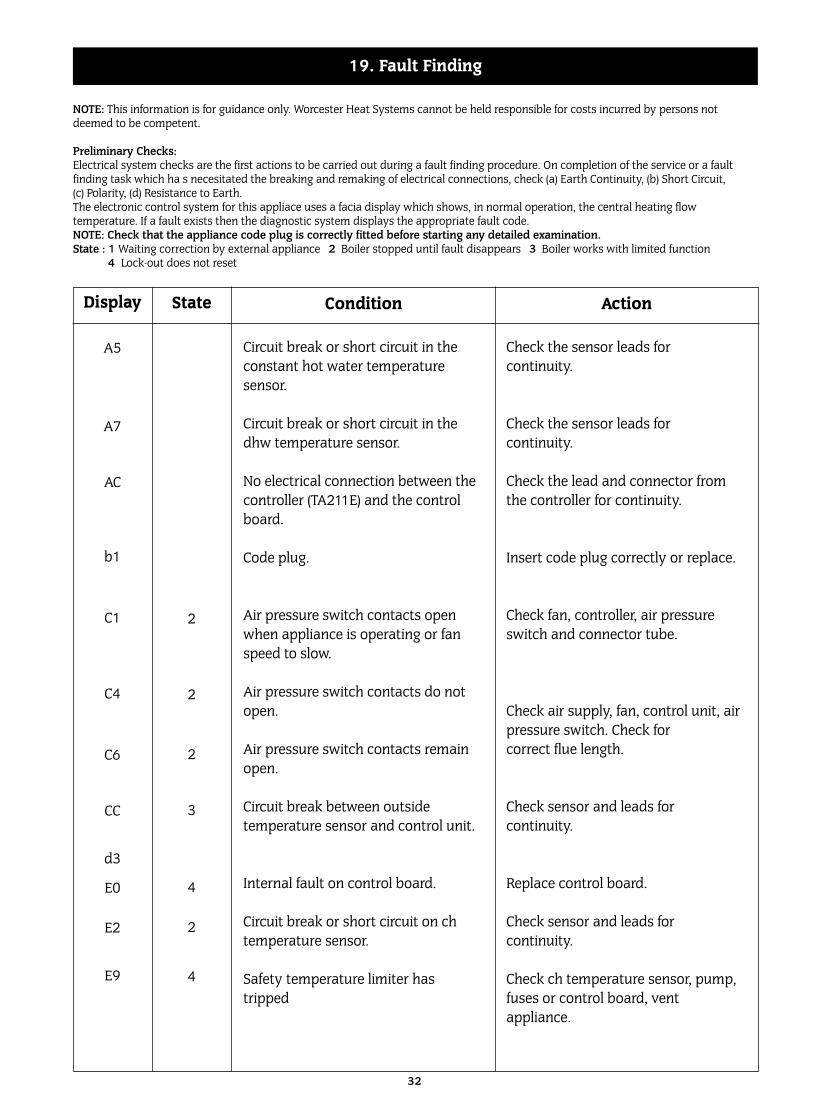
NOTE: This information is for guidance only. Worcester Heat Systems cannot be held responsible for costs incurred by persons notdeemed to be competent.
Preliminary Checks:Electrical system checks are the first actions to be carried out during a fault finding procedure. On completion of the service or a faultfinding task which ha s necesitated the breaking and remaking of electrical connections, check (a) Earth Continuity, (b) Short Circuit, (c) Polarity, (d) Resistance to Earth.The electronic control system for this appliace uses a facia display which shows, in normal operation, the central heating flowtemperature. If a fault exists then the diagnostic system displays the appropriate fault code. NOTE: Check that the appliance code plug is correctly fitted before starting any detailed examination.State : 1 Waiting correction by external appliance 2 Boiler stopped until fault disappears 3 Boiler works with limited function
4 Lock-out does not reset
19. Fault Finding
Display
A5
A7
AC
b1
C1
C4
C6
CC
d3
E0
E2
E9
Condition
Circuit break or short circuit in theconstant hot water temperature sensor.
Circuit break or short circuit in thedhw temperature sensor.
No electrical connection between thecontroller (TA211E) and the controlboard.
Code plug.
Air pressure switch contacts openwhen appliance is operating or fanspeed to slow.
Air pressure switch contacts do notopen.
Air pressure switch contacts remainopen.
Circuit break between outside temperature sensor and control unit.
Internal fault on control board.
Circuit break or short circuit on chtemperature sensor.
Safety temperature limiter hastripped
Action
Check the sensor leads for continuity.
Check the sensor leads for continuity.
Check the lead and connector fromthe controller for continuity.
Insert code plug correctly or replace.
Check fan, controller, air pressureswitch and connector tube.
Check air supply, fan, control unit, airpressure switch. Check for correct flue length.
Check sensor and leads for continuity.
Replace control board.
Check sensor and leads for continuity.
Check ch temperature sensor, pump,fuses or control board, vent appliance.
State
2
2
2
3
4
2
4
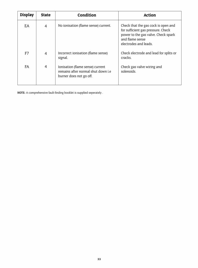
33
Display
EA
F7
FA
Condition
No ionisation (flame sense) current.
Incorrect ionisation (flame sense)signal.
Ionisation (flame sense) currentremains after normal shut down i.eburner does not go off.
Action
Check that the gas cock is open andfor sufficient gas pressure. Checkpower to the gas valve. Check sparkand flame sense electrodes and leads.
Check electrode and lead for splits orcracks.
Check gas valve wiring and solenoids.
State
4
4
4
NOTE: A comprehensive fault-finding booklet is supplied seperately .

34

35

This booklet is accurate at the date of printing but will be superseded and should be disregarded if specifications and/or appearances are changed in the interestsof continued improvement.
All goods sold are subject to our official Conditions of Sale, a copy of which may be obtained on application.
PUBLICATION 6 720 610 096 (99.07)
EXCELLENCE COMES AS STANDARDWorcester Heat Systems Limited, Cotswold Way, Warndon, Worcester WR4 9SW.
Telephone: (01905) 754624. Fax: (01905) 754619.Bosch Care Call (0990) 266241