warm - mestek
TRANSCRIPT

Indirect FiredDuct FurnacesIndirect FiredDuct Furnaces
○
○
○
○
○
○
○
○
○
○
○
○
○
○
○
Warm
Temprite
Keeps You
TGGTD-1
Technical Guide for:
○
○
○
○
○
○
○
○
○
○
○
○
• GTD Two Pass
• GTDM Four Pass
GTDM Series
GTD Series

2
○
○
○
○
○
○
○
○
○
○
○
○
○
Temprite
Keeps You
Warm
Temprite
Keeps You
Warm
In the business of industrial heating, efficient and low-cost operation is essential. Tempritekeeps you warm for less.
Since 1963, Temprite has been providing cost-effective, reliable heating solutions. Our provenIndirect Fired Duct Furnaces adds warm clean air to your work environment, but without theproducts of combustion in the airstream.
This Technical Guide will help you choose an Temprite Indirect Fired Gas Duct Furnace toprovide efficient, cost-effective heating and ventilation for your facility. The Guide covers:
• Technical Specifications — Configure the right system components (e.g., motors, drive,filter, options, etc.) to meet your needs.
– Model “GTD” for two pass units– Model “GTDM” for four pass units
• Installation Information — Plan details of on-site installation (dimensions, gas piping, etc.).
If you have questions, please contact Temprite’s Customer Service Department at 214-638-6010.We’ll be glad to help.
Indirect FiredDuct FurnacesTechnical Guide

3
○
○
○
○
○
○
○
○
○
○
○
○
○
Engineering Data – GTD Series ................................... 4
Dimensions – GTD Series ............................................. 5
Pressure Drop Charts
GTD-160 Duct Furnace ...................................... 6
GTD-320 Duct Furnace ...................................... 7
GTD-480 Duct Furnace ...................................... 8
GTD-800 Duct Furnace ...................................... 9
GTD-1120 Duct Furnace .................................. 10
Typical Gas Piping Layout – GTD Series .................... 11
Typical Wiring Diagram
GTD-160 & 320 ................................................ 12
GTD-480 .......................................................... 13
GTD-800 & 1120 .............................................. 14
Guide Specification – GTD Series .............................. 15
Engineering Data – GTDM Series ......................... 16-17
Dimensions – GTDM Series .................................. 18-19
Pressure Drop Charts
GTDM-25 – 40 Duct Furnace ........................... 20
GTDM-45 – 55 Duct Furnace ........................... 21
GTDM-65 – 75 Duct Furnace ........................... 22
GTDM-85 – 100 Duct Furnace ......................... 23
GTDM-125 – 175 Duct Furnace ....................... 24
GTDM-200 – 250 Duct Furnace ....................... 25
GTDM-275 – 300 Duct Furnace ....................... 26
GTDM-325 – 400 Duct Furnace ....................... 27
GTDM-500 – 600 Duct Furnace ....................... 28
Typical Gas Piping Layout – GTDM Series ................ 29
Typical Wiring Diagram ............................................. 30
Guide Specification – GTDM Series ........................... 31

4
Model SizeInput B.T.U./Hour (Maximum)Output B.T.U./Hour(B)Input B.T.U./Hour (Minimum)Natural Gas at 1,000 B.T.U./C.F.Nat. Gas Std. Pipe Size (7” W.C.)Manifold PressureOrifice SizePropane Fuel at 2,500 B.T.U./C.F.L. P. Gas Std. Pipe Size (11” W.C.)Manifold PressureOrifice SizeMinimum AirflowMaximum AirflowCombustion Air Requirements (CFM)Recommended Minimum Stack Size DiameterMaximum Vent Length - Equivalent Length (Ft)Primary Heating Surface – Sq. FeetSecondary Htg. Surface (Tubes & Headers) – Sq. FeetPrimary Combustion Volume – Cu. FeetSecondary Combustion Volume – Cu. FeetTotal Combustion Chamber Volume – Cu. Feet115 Volt, 1 Phase230 Volt, 1 Phase200 Volt, 3 Phase230 Volt, 3 Phase460 Volt, 3 Phase575 Volt, 3 Phase
160 320 480 800 1120200,000 400,000 600,000 1,000,000 1,400,000160,000 320,000 480,000 800,000 1,120,000100,000 100,000 86,000 294,118 435,294
200 400 600 1,000 1,4003/4” 3/4” 1” 1” 1-1/4”1.5 2.8 4.7 2.0 2.0#4 NR NR NR NR80 160 240 400 560
3/4” 3/4” 1” 1” 1-1/4”1.5 2.2 2.5 1.7 1.2#2 #6 NR NR NR
1,481 2,963 4,444 7,407 10,3704,938 9,877 14,815 24,691 34,568
39 77 115 192 2684” 6” 7” 9” 10”50 50 50 50 50
13.49 21.35 32.97 51.21 66.6516.23 27.87 45.75 65.46 94.183.47 6.94 12.73 25.75 39.490.93 1.74 2.76 4.22 5.644.40 8.68 15.49 29.97 45.138.70 8.70 13.04 13.04 13.044.35 4.35 6.52 6.52 6.525.00 5.00 7.50 7.50 7.504.35 4.35 6.52 6.52 6.522.17 2.17 3.26 3.26 3.261.74 1.74 2.61 2.61 2.61
SIZE &CAPACITY
FIRING RATE &MANIFOLD SIZE
SUPPLY AIRCAPACITY
COMBUSTION AIR& VENTING
REQUIREMENTSINTERNAL DATA OFHEAT EXCHANGER
(A)
AMP DRAW
Engineering Data – GTD Series
Capacity and Internal Data
(A) Standard construction - 400 series stainless steel primary and secondary material.
(B) Based on 80% operating efficiency.
5
ApproximateWeight 508 685 83712371713
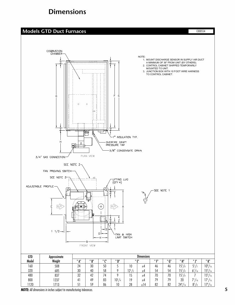
Dimensions
Models GTD Duct Furnaces C000554
160320480800
1120
Dimensions" D"599
101/4
10
" C"5058748386
" B"3040424959
" A"2430324151
" E" " H"157/8
157/8
157/8
20249/16
" K"109/16
159/16
159/16
171/16
179/16
10121/2
151928
GTDModel " F"
4654707982
" G"4654707982
" J"51/2
67/16
771/16
87/8
NOTE: All dimensions in inches subject to manufacturing tolerances.
±4±4±4±4±14

6
Pressure Drop Chart
Model GTD-160
GT
D 1
60 A
ir S
ide
Pre
ssu
re D
rop
- 8
in
ch p
rofi
le
0.00
0.10
0.20
0.30
0.40
0.50
0.60
1400
1800
2200
2600
3000
3400
3800
4200
4600
5000
CF
M
Pressure Drop - Inches Water Column

7
Pressure Drop Chart
Model GTD-320
GT
D 3
20 A
ir S
ide
Pre
ssu
re D
rop
- A
vera
ged
0.00
0.10
0.20
0.30
0.40
0.50
0.60
0.70
0.80
0.90
1.00
2800
3800
4800
5800
6800
7800
8800
9800
CF
M
Pressure Drop - Inches Water Column
8
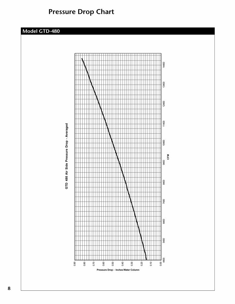
Pressure Drop Chart
Model GTD-480
GT
D 4
80 A
ir S
ide
Pre
ssu
re D
rop
- A
vera
ged
0.00
0.10
0.20
0.30
0.40
0.50
0.60
0.70
0.80
0.90
4400
5400
6400
7400
8400
9400
1040
011
400
1240
013
400
1440
0
CF
M
Pressure Drop - Inches Water Column

9
Pressure Drop Chart
Model GTD-800
GT
D 8
00 A
ir S
ide
Pre
ssu
re D
rop
- A
vera
ged
0
0.2
0.4
0.6
0.81
1.2
1.4
1.6 7
00
09
00
01
10
00
13
00
01
50
00
17
00
01
90
00
21
00
02
30
00
25
00
0
CFM
Pressure Drop - inches Water Column

10
Pressure Drop Chart
Model GTD-1120
GT
D 1
120
Air
Sid
e P
ress
ure
Dro
p -
Ave
rag
ed
0
0.2
0.4
0.6
0.81
1.2
1.4
1.6 10
000
1200
014
000
1600
018
000
2000
022
000
2400
026
000
2800
030
000
3200
034
000
CFM
Pressure Drop - Inches Water Column

11
Gas Piping Layout
Schematic Component Diagrams
NOTES:1. Vent limiting devices provided wherever possible, when venting is required the venting to
outside is by others on indoor units and furnished by factory on outdoor units.
2. For inlet pressures under 7” W.C. please consult factory.
C000558
COMPONENT IDENTIFICATIONGP-01 HIGH GAS PRESSURE REGULATOR (OPTIONAL)GP-05 MAIN GAS PRESSURE REGULATORGP-09 PILOT GAS PRESSURE REGULATORGP-11 FIRING VALVEGP-13 PILOT FIRING VALVEGP-27 NEEDLE ORIFICE VALVEGP-39 BUTTERFLY VALVEMT-11 MODULATING VALVE MOTOR
*VG-01 PILOT GAS VALVEVG-02 MAIN GAS VALVEVG-03 AUXILARY GAS VALVEVG-04 N/O VENT VALVEPS-02 BURNER AIR FLOW SWITCHPS-04 LOW GAS PRESSURE SWITCHPS-07 HIGH GAS PRESSURE SWITCH

12
Wiring Diagram
Typical Wiring Diagram – GTD-160 & 320 C000560

13
Wiring Diagram
Typical Wiring Diagram – GTD-480 C000559

14
Wiring Diagram
Typical Wiring Diagram – GTD-800 Through 1120 C000561
15
○
○
○
○
○
○
○
○
○
○
○
○
○
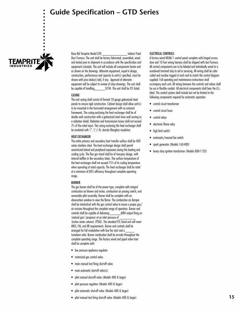
Guide Specification – GTD Series
Base Bid Temprite Model GTD ______________ Indirect FiredDuct Furnace. The unit shall be factory fabricated, assembled, wiredand tested prior to shipment in accordance with the specification andequipment schedule. The unit will include all components herein andas shown on the drawings. Alternate equipment, equal in design,construction, performance and capacity to unit(s) specified, must beshown with price deduct/add, if any. Approval of alternateequipment will be subject to review of shop drawings. The unit shallbe capable of handling______SCFM. The unit shall be ETL listed.
CASINGThe unit casing shall consist of formed 18 gauge galvanized steelpanels to ensure rigid construction. Cabinet design shall allow unit(s)to be mounted in the horizontal arrangement with no externalframework. The casing enclosing the heat exchanger shall be ofdouble wall construction with a galvanized steel inner wall serving asa radiation shield. Radiation and transmission losses shall not exceed2% of the rated input. The casing enclosing the heat exchanger shallbe insulated with 1", 11/2 lb. density fiberglass insulation.
HEAT EXCHANGERThe entire primary and secondary heat transfer surface shall be 400series stainless steel. The heat exchanger design shall permitunrestricted lateral and peripheral expansion during the heating andcooling cycle. The flue gas travel shall be of two-pass design, withinternal baffles in the secondary tubes. The surface temperature ofthe heat exchanger shall not exceed 75% of its scaling temperaturewhen operating at rated capacity. The heat exchanger shall be ratedat a minimum of 80% efficiency throughout complete operatingrange.
BURNERThe gas burner shall be of the power type, complete with integralcombustion air blower and motor, combustion air proving switch, andremovable pilot assembly. Burner shall be complete with anobservation window to view the flame. The combustion air dampershall be interlocked with the gas control valve to insure a proper gas/air mixture throughout the complete range of operation. Burner andcontrols shall be capable of delivering ______MBH output firing on(natural gas) (propane) at an inlet pressure of _________(inches water column) (PSIG). The standard ETL listed unit will meetANSI, FM, and IRI requirements. Burner and controls shall bearranged for full modulation with low fire start and a _____turndown ratio. Burner combustion shall be on-ratio throughout thecomplete operating range. The factory wired and piped valve trainshall be complete with:
• low pressure appliance regulator
• motorized gas control valve
• main manual test firing shut-off valve
• main automatic shut-off valve(s)
• pilot manual shut-off valve (Models 480 & larger)
• pilot pressure regulator (Models 480 & larger)
• pilot automatic shut-off valve (Models 480 & larger)
• pilot manual test firing shut-off valve (Models 480 & larger)
ELECTRICAL CONTROLSA factory wired NEMA 1 control panel complete with hinged accessdoor and 10 foot wiring harness shall be shipped with duct furnace.All control components are to be labeled and individually wired to anumbered terminal strip to aid in servicing. All wiring shall be colorcoded and number tagged at each end to match the control diagramsupplied. Full operating and maintenance instructions shallaccompany each unit. All wiring between the controls and valves shallbe run in flexible conduit. All electrical components shall bear the U.L.label. The control system shall include but not be limited to thefollowing components required for automatic operation:
• control circuit transformer
• control circuit fuses
• control relays
• electronic flame relay
• high limit switch
• automatic/manual fan switch
• spark generator (Models 160-480)
• heavy duty ignition transformer (Models 800-1120)

16
Model SizeInput MBHOutput MBH(A)Natural Gas @ 1,000 B.T.U./C.F.Gas Connection @ 7” W.C. (Natural Gas)Gas Connection @ 14” W.C. (Natural Gas)Combustion Air Required (C.F.M.)Exhauster ModelExhauster H.P.Burner H.P.Recommended Min. Stack Size – Dia.200 Volt, 3 Phase230 Volt, 3 Phase460 Volt, 3 Phase575 Volt, 3 Phase
25 35 40 50 55312 437 500 625 687250 350 400 500 550312 437 500 625 6873/4” 3/4” 1” 1” 1”3/4” 3/4” 3/4” 3/4” 1”80 110 130 160 18012 12 12 12 12
1/3 1/3 1/3 1/3 1/31/3 1/3 1/3 1/3 1/38” 8” 8” 8” 8”
21.9 21.9 16.3 16.3 16.320.9 20.9 15.1 15.1 15.117.7 17.7 11.2 11.2 11.217.0 17.0 10.4 10.4 10.4
Model SizeInput MBHOutput MBH(A)Natural Gas @ 1,000 B.T.U./C.F.Gas Connection @ 7” W.C. (Natural Gas)Gas Connection @ 14” W.C. (Natural Gas)Combustion Air Required (C.F.M.)Exhauster ModelExhauster H.P.Burner H.P.Recommended Min. Stack Size – Dia.200 Volt, 3 Phase230 Volt, 3 Phase460 Volt, 3 Phase575 Volt, 3 Phase
SIZE &CAPACITY
FIRING RATE &MANIFOLD SIZE
EQUIPMENT DATA
AMP DRAW (B)
65 75 85 100 125812 987 1,062 1,250 1,562650 750 850 1,000 1,250812 987 1,062 1,250 1,562
11/4” 11/4” 11/4” 11/2” 11/2”1” 1” 1” 1” 11/4”
210 240 275 325 40012 12 14 14 18
1/3 1/3 1/2 1/2 21/3 1/3 1/3 1/3 1/210” 10” 10” 10” 12”16.3 16.3 17.2 19.7 26.715.1 15.1 15.9 18.1 24.511.2 11.2 11.6 12.6 17.110.4 10.4 10.7 11.6 15.7
SIZE &CAPACITY
FIRING RATE &MANFOLD SIZE
EQUIPMENT DATA
AMP DRAW (B)
Engineering Data – GTDM Series
Capacity and Internal Data
(A) Based on 80% operating efficiency.
(B) Based on G-P burners.

17
Model SizeInput MBHOutput MBH(A)Natural Gas @ 1,000 B.T.U./C.F.Gas Connection @ 7” W.C. (Natural Gas)Gas Connection @ 14” W.C. (Natural Gas)Combustion Air Required (C.F.M.)Exhauster ModelExhauster H.P.Burner H.P.Recommended Min. Stack Size – Dia.200 Volt, 3 Phase230 Volt, 3 Phase460 Volt, 3 Phase575 Volt, 3 Phase
150 175 200 250 2751,875 2,187 2,500 3,125 3,4381,500 1,750 2,000 2,500 2,7501,875 2,187 2,500 3,125 3,438
2” 2” 2” 2” 21/2”11/2” 11/2” 11/2” 2” 2”480 560 650 800 88018 18 18 21 212 2 2 3 3
1/2 1/2 1/2 1 112” 12” 12” 12” 14”26.7 27.6 27.6 19.6 19.624.5 25.3 25.3 17.1 17.117.1 17.5 17.5 8.5 8.515.7 16.0 16.0 6.8 6.8
Model SizeInput MBHOutput MBH(A)Natural Gas @ 1,000 B.T.U./C.F.Gas Connection @ 7” W.C. (Natural Gas)Gas Connection @ 14” W.C. (Natural Gas)Combustion Air Required (C.F.M.)Exhauster ModelExhauster H.P.Burner H.P.Recommended Min. Stack Size – Dia.200 Volt, 3 Phase230 Volt, 3 Phase460 Volt, 3 Phase575 Volt, 3 Phase
SIZE &CAPACITY
FIRING RATE &MANIFOLD SIZE
EQUIPMENT DATA
AMP DRAW (B)
300 350 400 500 6003,750 4,375 5,000 6,250 7,5003,000 3,500 4,000 5,000 6,0003,750 4,375 5,000 6,250 7,50021/2” 3” 3” NA NA
2” 2” 21/2” 3” 3”960 1,120 1,300 1,600 1,92021 21 21 21 213 3 3 5 51 1-1/2 2 3 5
14” 14” 14” 18” 18”19.6 21.7 22.6 32.3 38.717.1 18.9 19.7 28.1 33.78.5 9.4 9.8 14.0 16.86.8 7.5 7.9 11.2 13.5
SIZE &CAPACITY
FIRING RATE &MANFOLD SIZE
EQUIPMENT DATA
AMP DRAW (B)
Engineering Data – GTDM Series
Capacity and Internal Data
(A) Based on 80% operating efficiency.
(B) Based on G-P burners.
18
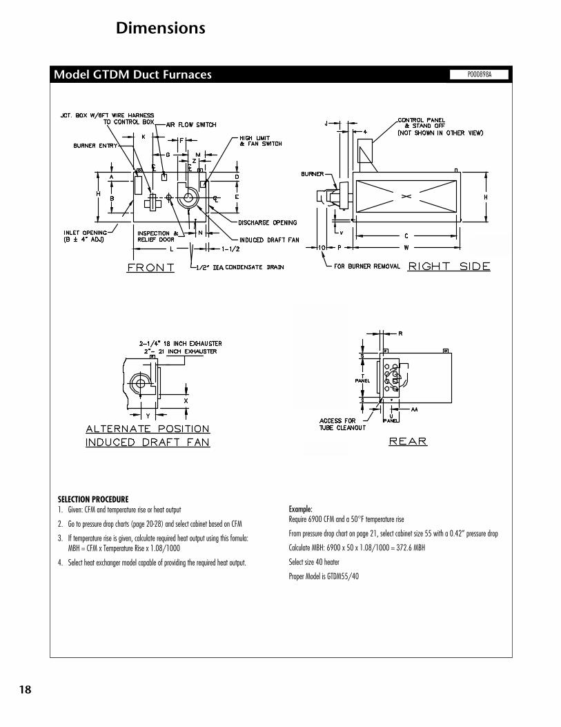
Dimensions
Model GTDM Duct Furnaces P000898A
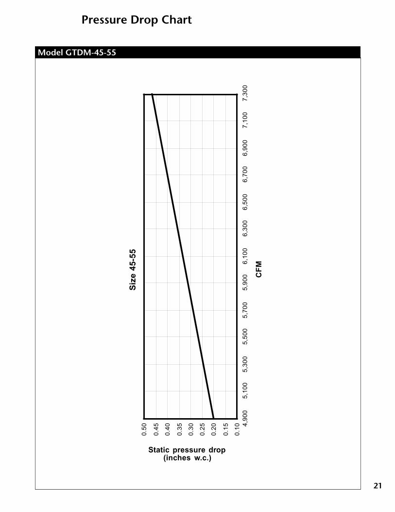
SELECTION PROCEDURE1. Given: CFM and temperature rise or heat output
2. Go to pressure drop charts (page 20-28) and select cabinet based on CFM
3. If temperature rise is given, calculate required heat output using this fomula:MBH = CFM x Temperature Rise x 1.08/1000
4. Select heat exchanger model capable of providing the required heat output.
Example:Require 6900 CFM and a 50°F temperature rise
From pressure drop chart on page 21, select cabinet size 55 with a 0.42” pressure drop
Calculate MBH: 6900 x 50 x 1.08/1000 = 372.6 MBH
Select size 40 heater
Proper Model is GTDM55/40

19
"J"63/8
63/8
63/8
63/8
63/8
63/8
73/8
73/8
73/8
73/8
93/8
93/8
93/8
93/8
93/8
111/8
111/8
111/8
111/8
111/8
111/8
111/8
111/8
111/8
25, 35 or 4055/25, 35 or 4075/25, 35 or 40
45 or 5575/45 or 55
100/45 or 5565 or 75
100/65 or 7585 or 100
175/85 or 100125, 150 or 175
250/125, 150 or 175200
300/200400/200
250300/250400/250
275 or 300400/275 or 300600/275 or 300325, 350 or 400
600/325, 350 or 400500, 550 or 600
Dimensions
Model GTDM Duct FurnacesDimensions
"D"79999
159
151515151515
171/2
2015
171/2
20171/2
2016201616
"C"4456765676867686869696
116116136154116136154136154174154174174
"B"9
11101/2
11101/2
14101/2
1414161621192121212121212123212323
"A"111/2
121/2
123/4
121/2
123/4
17123/4
17171919
191/2
201/2
22241/2
191/2
22241/2
22241/2
281/2
241/2
281/2
281/2
"E"181818181818181818242430303030303030303048304848
"G"242424282828282832323737373737373737434343
571/4
571/4
793/4
"K"13131315151515152424
221/2
221/2
221/2
221/2
221/2
221/2
221/2
221/2
272727
311/4
311/4
461/4
"L"474747555555555568687272727272727272848484
100100141
"M"10101012121212121212
121/2
121/2
121/2
121/2
121/2
121/2
121/2
121/2
141414
111/2
111/2
15
Model "F"61/4
61/4
61/4
61/4
61/4
61/4
777799999
105/8
105/8
105/8
105/8
105/8
105/8
105/8
105/8
105/8
"H"323636363648364848545460606570606570657080708080
NOTE: All dimensions in inches subject to manufacturing tolerances.
ApproximateWeight102511001220128013551688160018332250247531803230422541715444440045375716550060026423660068518871
"X"65/8
85/8
85/8
85/8
85/8
145/8
71/4
131/4
131/4
161/4
131/4
161/4
161/4
163/8
187/8
137/8
163/8
187/8
163/8
187/8
237/8
187/8
237/8
237/8
25, 35 or 4055/25, 35 or 4075/25, 35 or 40
45 or 5575/45 or 55
100/45 or 5565 or 75
100/65 or 7585 or 100
175/85 or 100125, 150 or 175
250/125, 150 or 175200
300/200400/200
250300/250400/250
275 or 300400/275 or 300600/275 or 300325, 350 or 400
600/325, 350 or 400500, 550 or 600
Dimensions"S"24444
104
1051/4
81/4
58
73/8
97/8
123/8
73/8
97/8
123/8
461/2
111/2
61/2
111/2
61/4
"R"222222
31/4
31/4
31/2
31/2
31/2
31/2
23/8
23/8
23/8
23/8
23/8
23/8
21/2
21/2
21/2
33/4
33/4
4
" P"171717171717171717172121212121262626262626323232
"N"191/4
191/4
191/4
211/4
211/4
211/4
211/4
211/4
203/4
203/4
223/4
223/4
223/4
223/4
223/4
223/4
223/4
223/4
261/4
261/4
261/4
211/4
211/4
271/4
"T"2828282828282828
371/2
371/2
4444
451/4
451/4
451/4
451/4
451/4
451/4
5757575757
671/2
"V"466
51/8
51/8
111/8
51/8
111/8
67/8
111/8
51/2
97/8
61/2
81/2
961/2
81/2
96
81/2
131/2
81/2
131/2
81/2
"Y"999999
101/2
101/2
101/2
101/2
131/2
131/2
131/2
131/2
131/2
151/2
151/2
151/2
151/2
151/2
151/2
151/2
151/2
151/2
"Z"81/4
81/4
81/4
81/4
81/4
81/4
91/2
91/2
91/2
91/2
1313131313
141/4
141/4
141/4
141/4
141/4
141/4
141/4
141/4
141/4
"AA"201/4
201/4
201/4
201/4
201/4
201/4
221/4
221/4
213/4
221/4
213/4
213/4
253/4
253/4
253/4
253/4
331/4
311/4
321/4
253/4
321/4
331/4
331/4
311/4
Model "U"161616161616161616161616
211/4
211/4
211/4
211/4
211/4
211/4
272727272725
" W"486080608090809090
100100120120140160120140160140160180160180180
ApproximateWeight102511001220128013551688160018332250247531803230422541715444440045375716550060026423660068518871

20
Pressure Drop Chart
Model GTDM-25-40
Siz
e 25
-40
0.0
00
.05
0.1
00
.15
0.2
0
0.2
50
.30
0.3
50
.40
0.4
50
.50 2,
500
2,70
02,
900
3,10
03,
300
3,50
03,
700
3,90
04,
100
4,30
04,
500
4,70
04,
900
5,10
05,
300
5,50
0
CF
M
Static pressure drop (inches w.c.)
21
Pressure Drop Chart
Model GTDM-45-55
Siz
e 45
-55
0.10
0.15
0.20
0.25
0.30
0.35
0.40
0.45
0.50
4,90
05,
100
5,30
05,
500
5,70
05,
900
6,10
06,
300
6,50
06,
700
6,90
07,
100
7,30
0
CF
M
Static pressure drop (inches w.c.)

22
Pressure Drop Chart
Model GTDM-65-75
Siz
e 65
-75
0.10
0.15
0.20
0.25
0.30
0.35
0.40
0.45
0.50
7,00
07,
500
8,00
08,
500
9,00
09,
500
10,0
00
CFM
Static pressure drop (inches w.c.)

23
Pressure Drop Chart
Model GTDM-85-100
Siz
e 85
-100
0.1
0
0.1
5
0.2
0
0.2
5
0.3
0
0.3
5
0.4
0
0.4
5
0.5
0 9,00
09,
500
10,0
0010
,500
11,0
0011
,500
12,0
0012
,500
13,0
00
CFM
Static pressure drop (inches w.c.)
24
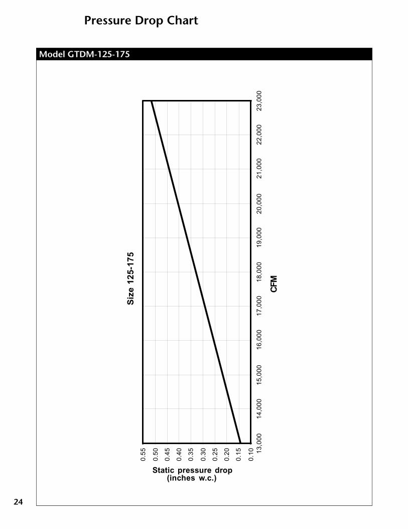
Pressure Drop Chart
Model GTDM-125-175
Siz
e 12
5-17
5
0.10
0.15
0.20
0.25
0.30
0.35
0.40
0.45
0.50
0.55 13
,000
14,0
0015
,000
16,0
0017
,000
18,0
0019
,000
20,0
0021
,000
22,0
0023
,000
CFM
Static pressure drop (inches w.c.)
25
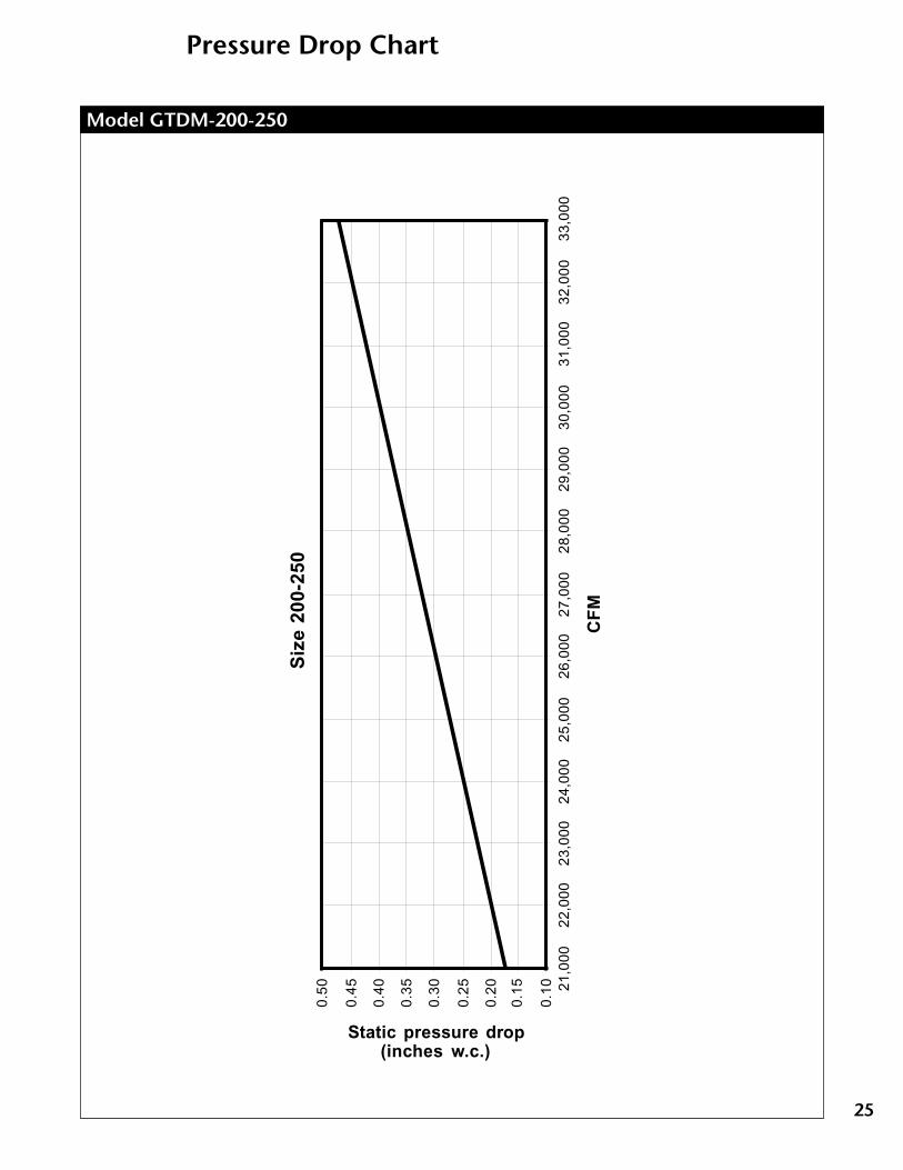
Pressure Drop Chart
Model GTDM-200-250
Siz
e 20
0-25
0
0.10
0.15
0.20
0.25
0.30
0.35
0.40
0.45
0.50 21
,000
22,0
0023
,000
24,0
0025
,000
26,0
0027
,000
28,0
0029
,000
30,0
0031
,000
32,0
0033
,000
CF
M
Static pressure drop (inches w.c.)

26
Pressure Drop Chart
Model GTDM-275-300
Siz
e 27
5-30
0
0.10
0.15
0.20
0.25
0.30
0.35
0.40
0.45
0.50 29
,000
30,0
0031
,000
32,0
0033
,000
34,0
0035
,000
36,0
0037
,000
38,0
0039
,000
CF
M
Static pressure drop
(inches w.c.)

27
Pressure Drop Chart
Model GTDM-325-400
Siz
e 32
5-40
0
0.10
0.15
0.20
0.25
0.30
0.35
0.40
0.45
0.50 35
,000
37,0
0039
,000
41,0
0043
,000
45,0
0047
,000
49,0
0051
,000
53,0
00
CF
M
Static pressure drop (inches w.c.)
28
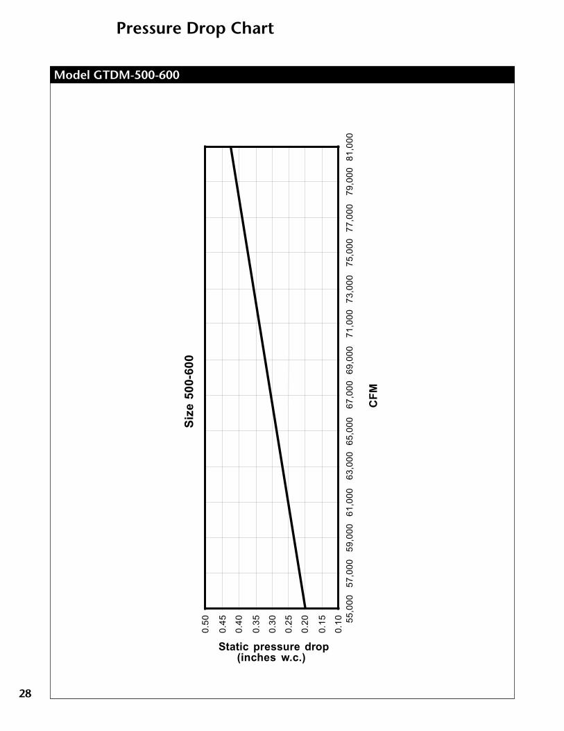
Pressure Drop Chart
Model GTDM-500-600
Siz
e 50
0-60
0
0.10
0.15
0.20
0.25
0.30
0.35
0.40
0.45
0.50 55
,000
57,0
0059
,000
61,0
0063
,000
65,0
0067
,000
69,0
0071
,000
73,0
0075
,000
77,0
0079
,000
81,0
00
CF
M
Static pressure drop (inches w.c.)
29
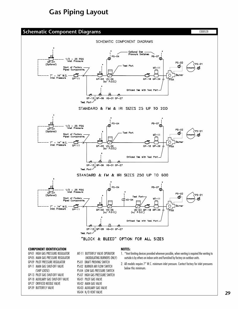
Gas Piping Layout
Schematic Component Diagrams
NOTES:1. *Vent limiting devices provided wherever possible, when venting is required the venting to
outside is by others on indoor units and furnished by factory on outdoor units.
2. All models require 7” W.C. minimum inlet pressure. Contact factory for inlet pressuresbelow this minimum.
C000528
COMPONENT IDENTIFICATIONGP-01 HIGH GAS PRESSURE REGULATORGP-05 MAIN GAS PRESSURE REGULATORGP-09 PILOT PRESSURE REGULATORGP-11 MAIN GAS SHUT-OFF VALVE (SHIP LOOSE)GP-13 PILOT GAS SHUT-OFF VALVEGP-18 AUXILIARY GAS SHUT-OFF VALVEGP-27 ORIFICED NEEDLE VALVEGP-39 BUTTERFLY VALVE
MT-11 BUTTERFLY VALVE OPERATOR(MODULATING BURNERS ONLY)
PS-01 DRAFT PROVING SWITCHPS-02 BURNER AIR FLOW SWITCHPS-04 LOW GAS PRESSURE SWITCHPS-07 HIGH GAS PRESSURE SWITCHVG-01 PILOT GAS VALVEVG-02 MAIN GAS VALVEVG-03 AUXILIARY GAS VALVEVG-04 N/O VENT VALVE

30
Wiring Diagram
Typical Wiring Diagram – GTDM C000565

31
○
○
○
○
○
○
○
○
○
○
○
○
○
Base Bid Temprite Model GTDM ______________ IndirectFired Duct Furnace. The unit shall be factory fabricated, assembled,wired and tested prior to shipment in accordance with thespecification and equipment schedule. The unit will include allcomponents herein and as shown on the drawings. Alternateequipment, equal in design, construction, performance and capacityto unit(s) specified, must be shown with price deduct/add, if any.Approval of alternate equipment will be subject to review of shopdrawings. The unit shall be capable of handling______SCFM. Theunit shall be ETL listed.
CASINGThe unit casing is to be panel construction from 16 gauge galvanizedsteel, suitably reinforced to ensure rigidity. All panels shall be factorysealed with caulking between mating panels. The casing enclosingthe heat exchanger shall be of double wall construction with agalvanized steel inner wall serving as a radiation shield. Radiationand transmission losses shall not exceed 11/2% of the rated output.This section shall be insulated with 1", 11/2 lb. density insulation.
The unit shall have an integral milled channel base complete withlifting lugs.
INDIRECT GAS FIRED SECTIONThe entire primary heat transfer surface and header shall be of 400series stainless steel; the secondary heat transfer surface shall be(mild steel) (400 series stainless steel). The heat exchanger designshall permit unrestricted lateral and peripheral expansion during theheating and cooling cycle. The flue gas travel shall be of four-passdesign, with no internal baffles. The surface temperature of the heatexchanger shall not exceed 75% of its scaling temperature whenoperating at rated capacity. The heat exchanger shall be rated at aminimum of 80% efficiency at rated output. A pressure relief doorcomplete with an observation window to view the complete flameand pilot shall be provided.
DIRECT DRIVE INDUCED DRAFT FANAn integrally mounted, heavy duty, non-clogging radial blade induceddraft fan complete with direct drive motor shall be provided. Theinduced draft fan shall be adequately sized to insure proper draftconditions when operating at rated capacity and equipped with amanual damper complete with locking quadrant to ensure properdraft and extended heat exchanger performance.
BURNERThe gas burner shall be of the power type, complete with integralcombustion air blower and motor, combustion air proving switch, andremovable pilot assembly. The combustion air damper shall beinterlocked with the gas control valve to insure a proper gas/airmixture throughout the complete range of operation. Burner andcontrols shall be capable of delivering ______MBH output firing on(natural gas) (propane) at an inlet pressure of _________(inches water column) (PSIG) and in accordance with(manufacturer's standard) (FM) (IRI) requirements. Burner andcontrols shall be arranged for ((High/Low/Off) (Full Modulation withlow fire start and up to a 10:1 turndown ratio). The factory wiredand piped valve train shall be mounted inside the unit weatherproofenclosure and be complete with:
• low pressure appliance regulator
• motorized gas control valve
• main manual test firing shut-off valve
• pilot manual shut-off valve
• pilot pressure regulator
• pilot automatic shut-off valve
• pilot manual test firing shut-off valve
ELECTRICAL CONTROLSA NEMA 1 control panel complete with hinged access door shall beprovided. All control components are to be labeled and individuallywired to a numbered terminal strip to aid in servicing. All wiring shallbe color coded and number tagged at each end to match the controldiagram supplied. Full operating and maintenance instructions shallaccompany each unit. All wiring between the controls and valves shallbe run in flexible conduit. All electrical components shall bear the U.L.label. The control system shall include but not be limited to thefollowing components required for automatic operation:
• control circuit transformer
• control circuit fuses
• control relays
• electronic flame relay complete with alarm contacts
• induced draft fan air proving differential switch
• high limit switch
• automatic/manual fan switch
• heavy duty ignition transformer
Guide Specification – GTDM Series
EfficientIndirect FiredDuctFurnaces
Temprite Industries
www.mestek.com
4830 Transport Drive Dallas TX 75247
Telephone 214.638.6010
Fax 214.905.0806
Choose Temprite Indirect Gas Duct Furnaces• Provide space heating or make-up air without products of combustion in the supply air
• Low operating and maintenance costs
• Simple, inexpensive installation
• Temprite, a leader in research, engineering, and customer service since 1963
GTDM Series
GTD Series
○
○
○
○
○
○
○
○