mestek outdoor air handling units - trane ·...
TRANSCRIPT

May 2017 MMUUAA--PPRRCC001111BB--EENN
Outdoor Air Handling UnitsFor use with Heating, Cooling, and VentilatingApplications
Product Catalog

©2017 Ingersoll Rand MUA-PRC011B-EN
CopyrightThis document and the information in it are the property of Trane, and may not be used or reproduced in whole or inpart without written permission. Trane reserves the right to revise this publication at any time, and to make changes toits content without obligation to notify any person of such revision or change.
TrademarksAll trademarks referenced in this document are the trademarks of their respective owners.

MUA-PRC011B-EN 3
Introduction . . . . . . . . . . . . . . . . . . . . . . . . . . . . . . . . . . . . . . . . . . . . . . . . . . . . . . . . . . . . . . . . . . . . . . . . . . . . . . . . . . . . . . 5Features and Benefits . . . . . . . . . . . . . . . . . . . . . . . . . . . . . . . . . . . . . . . . . . . . . . . . . . . . . . . . . . . . . . . . . . . . . . . . . . . 6
Rooftop Air Handler Unit Number Description . . . . . . . . . . . . . . . . . . . . . . . . . . . . . . . . . . . . . . . . . . . . . . . . . . . . 7
Packaged Rooftop Arrangements . . . . . . . . . . . . . . . . . . . . . . . . . . . . . . . . . . . . . . . . . . . . . . . . . . . . . . . . . . . . . . . . . 9
Packaged Rooftop Arrangement Reference . . . . . . . . . . . . . . . . . . . . . . . . . . . . . . . . . . . . . . . . . . . . . . . . . . . . . . 11
Accessory Pressure Loss. . . . . . . . . . . . . . . . . . . . . . . . . . . . . . . . . . . . . . . . . . . . . . . . . . . . . . . . . . . . . . . . . . . . . . . . . 12Air Handler Arrangements (B,C,D,E) . . . . . . . . . . . . . . . . . . . . . . . . . . . . . . . . . . . . . . . . . . . . . . . . . . . . . . . . . . . . . 12
Air Handler Arrangements (G,J,K,L) . . . . . . . . . . . . . . . . . . . . . . . . . . . . . . . . . . . . . . . . . . . . . . . . . . . . . . . . . . . . . 13
Air Handler Performance . . . . . . . . . . . . . . . . . . . . . . . . . . . . . . . . . . . . . . . . . . . . . . . . . . . . . . . . . . . . . . . . . . . . . . . . 14Air Handler Arrangement (B, C, D, E) . . . . . . . . . . . . . . . . . . . . . . . . . . . . . . . . . . . . . . . . . . . . . . . . . . . . . . . . . . . . 14
Rooftop Arrangement (G, J, K, L) . . . . . . . . . . . . . . . . . . . . . . . . . . . . . . . . . . . . . . . . . . . . . . . . . . . . . . . . . . . . . . . . 16
Dimensional Data. . . . . . . . . . . . . . . . . . . . . . . . . . . . . . . . . . . . . . . . . . . . . . . . . . . . . . . . . . . . . . . . . . . . . . . . . . . . . . . . 18Air Handler Arrangement B . . . . . . . . . . . . . . . . . . . . . . . . . . . . . . . . . . . . . . . . . . . . . . . . . . . . . . . . . . . . . . . . . . . . . 18
Air Handler Arrangement C . . . . . . . . . . . . . . . . . . . . . . . . . . . . . . . . . . . . . . . . . . . . . . . . . . . . . . . . . . . . . . . . . . . . . 18
Air Handler Arrangement D . . . . . . . . . . . . . . . . . . . . . . . . . . . . . . . . . . . . . . . . . . . . . . . . . . . . . . . . . . . . . . . . . . . . . 19
Air Handler Arrangement E . . . . . . . . . . . . . . . . . . . . . . . . . . . . . . . . . . . . . . . . . . . . . . . . . . . . . . . . . . . . . . . . . . . . . 19
Air Handler Arrangement G. . . . . . . . . . . . . . . . . . . . . . . . . . . . . . . . . . . . . . . . . . . . . . . . . . . . . . . . . . . . . . . . . . . . . 20
Air Handler Arrangement J . . . . . . . . . . . . . . . . . . . . . . . . . . . . . . . . . . . . . . . . . . . . . . . . . . . . . . . . . . . . . . . . . . . . . 20
Air Handler Arrangement K . . . . . . . . . . . . . . . . . . . . . . . . . . . . . . . . . . . . . . . . . . . . . . . . . . . . . . . . . . . . . . . . . . . . . 21
Air Handler Arrangement L . . . . . . . . . . . . . . . . . . . . . . . . . . . . . . . . . . . . . . . . . . . . . . . . . . . . . . . . . . . . . . . . . . . . . 21
Evaporative Cooling . . . . . . . . . . . . . . . . . . . . . . . . . . . . . . . . . . . . . . . . . . . . . . . . . . . . . . . . . . . . . . . . . . . . . . . . . . . . . 22Air Handler Arrangements D, E. . . . . . . . . . . . . . . . . . . . . . . . . . . . . . . . . . . . . . . . . . . . . . . . . . . . . . . . . . . . . . . . . . 22
Evaporative Cooling Modules. . . . . . . . . . . . . . . . . . . . . . . . . . . . . . . . . . . . . . . . . . . . . . . . . . . . . . . . . . . . . . . . . . . 23
Cooling Coil Options . . . . . . . . . . . . . . . . . . . . . . . . . . . . . . . . . . . . . . . . . . . . . . . . . . . . . . . . . . . . . . . . . . . . . . . . . . . 26
Component Descriptions . . . . . . . . . . . . . . . . . . . . . . . . . . . . . . . . . . . . . . . . . . . . . . . . . . . . . . . . . . . . . . . . . . . . . . . . 31Supply Voltage . . . . . . . . . . . . . . . . . . . . . . . . . . . . . . . . . . . . . . . . . . . . . . . . . . . . . . . . . . . . . . . . . . . . . . . . . . . . . . . . 31
Motor Type. . . . . . . . . . . . . . . . . . . . . . . . . . . . . . . . . . . . . . . . . . . . . . . . . . . . . . . . . . . . . . . . . . . . . . . . . . . . . . . . . . . . 31
Motor Size . . . . . . . . . . . . . . . . . . . . . . . . . . . . . . . . . . . . . . . . . . . . . . . . . . . . . . . . . . . . . . . . . . . . . . . . . . . . . . . . . . . . 31
Air Inlet Configuration. . . . . . . . . . . . . . . . . . . . . . . . . . . . . . . . . . . . . . . . . . . . . . . . . . . . . . . . . . . . . . . . . . . . . . . . . . 32
Air Control and Damper Arrangement . . . . . . . . . . . . . . . . . . . . . . . . . . . . . . . . . . . . . . . . . . . . . . . . . . . . . . . . . . . 32
Table of Contents

4 MUA-PRC011B-EN
Accessories. . . . . . . . . . . . . . . . . . . . . . . . . . . . . . . . . . . . . . . . . . . . . . . . . . . . . . . . . . . . . . . . . . . . . . . . . . . . . . . . . . . . . . 34Mechanical Accessories . . . . . . . . . . . . . . . . . . . . . . . . . . . . . . . . . . . . . . . . . . . . . . . . . . . . . . . . . . . . . . . . . . . . . . . . 34
Filters . . . . . . . . . . . . . . . . . . . . . . . . . . . . . . . . . . . . . . . . . . . . . . . . . . . . . . . . . . . . . . . . . . . . . . . . . . . . . . . . . . . . . . . . . 34
Evaporative Cooler Accessories . . . . . . . . . . . . . . . . . . . . . . . . . . . . . . . . . . . . . . . . . . . . . . . . . . . . . . . . . . . . . . . . . 34
Time Clocks . . . . . . . . . . . . . . . . . . . . . . . . . . . . . . . . . . . . . . . . . . . . . . . . . . . . . . . . . . . . . . . . . . . . . . . . . . . . . . . . . . . 35
Electrical Accessories . . . . . . . . . . . . . . . . . . . . . . . . . . . . . . . . . . . . . . . . . . . . . . . . . . . . . . . . . . . . . . . . . . . . . . . . . . 35
Duct and Room Thermostats. . . . . . . . . . . . . . . . . . . . . . . . . . . . . . . . . . . . . . . . . . . . . . . . . . . . . . . . . . . . . . . . . . . . 35
Freeze and Fire Protection . . . . . . . . . . . . . . . . . . . . . . . . . . . . . . . . . . . . . . . . . . . . . . . . . . . . . . . . . . . . . . . . . . . . . . 37
Limits and Indicator Lamps . . . . . . . . . . . . . . . . . . . . . . . . . . . . . . . . . . . . . . . . . . . . . . . . . . . . . . . . . . . . . . . . . . . . . 37
Interlock Relays. . . . . . . . . . . . . . . . . . . . . . . . . . . . . . . . . . . . . . . . . . . . . . . . . . . . . . . . . . . . . . . . . . . . . . . . . . . . . . . . 38
Disconnect Switches (NEMA-3R) . . . . . . . . . . . . . . . . . . . . . . . . . . . . . . . . . . . . . . . . . . . . . . . . . . . . . . . . . . . . . . . . 38
Convenience Accessories. . . . . . . . . . . . . . . . . . . . . . . . . . . . . . . . . . . . . . . . . . . . . . . . . . . . . . . . . . . . . . . . . . . . . . . 39
VFD Options. . . . . . . . . . . . . . . . . . . . . . . . . . . . . . . . . . . . . . . . . . . . . . . . . . . . . . . . . . . . . . . . . . . . . . . . . . . . . . . . . . . 39
Component Locations . . . . . . . . . . . . . . . . . . . . . . . . . . . . . . . . . . . . . . . . . . . . . . . . . . . . . . . . . . . . . . . . . . . . . . . . . . 40
Roof Curb Kits . . . . . . . . . . . . . . . . . . . . . . . . . . . . . . . . . . . . . . . . . . . . . . . . . . . . . . . . . . . . . . . . . . . . . . . . . . . . . . . . . . . 41Standard Roof Curb Kits . . . . . . . . . . . . . . . . . . . . . . . . . . . . . . . . . . . . . . . . . . . . . . . . . . . . . . . . . . . . . . . . . . . . . . . . 41
Uninsulated Roof Curb Kits . . . . . . . . . . . . . . . . . . . . . . . . . . . . . . . . . . . . . . . . . . . . . . . . . . . . . . . . . . . . . . . . . . . . . 41
Vibration Isolation and Seismic Curbs . . . . . . . . . . . . . . . . . . . . . . . . . . . . . . . . . . . . . . . . . . . . . . . . . . . . . . . . . . . 41
Adaptor Curbs . . . . . . . . . . . . . . . . . . . . . . . . . . . . . . . . . . . . . . . . . . . . . . . . . . . . . . . . . . . . . . . . . . . . . . . . . . . . . . . . . 41
Dimensional Data . . . . . . . . . . . . . . . . . . . . . . . . . . . . . . . . . . . . . . . . . . . . . . . . . . . . . . . . . . . . . . . . . . . . . . . . . . . . . . 41
Specifications . . . . . . . . . . . . . . . . . . . . . . . . . . . . . . . . . . . . . . . . . . . . . . . . . . . . . . . . . . . . . . . . . . . . . . . . . . . . . . . . . 45
Assembly . . . . . . . . . . . . . . . . . . . . . . . . . . . . . . . . . . . . . . . . . . . . . . . . . . . . . . . . . . . . . . . . . . . . . . . . . . . . . . . . . . . . . 46
Unit/Curb End Rail Assembly . . . . . . . . . . . . . . . . . . . . . . . . . . . . . . . . . . . . . . . . . . . . . . . . . . . . . . . . . . . . . . . . . . . 46
Engineered Products Specification Guide. . . . . . . . . . . . . . . . . . . . . . . . . . . . . . . . . . . . . . . . . . . . . . . . . . . . . . . . 47
Approximate Unit Net and Ship Weights . . . . . . . . . . . . . . . . . . . . . . . . . . . . . . . . . . . . . . . . . . . . . . . . . . . . . . . . 54Air Handler Arrangements. . . . . . . . . . . . . . . . . . . . . . . . . . . . . . . . . . . . . . . . . . . . . . . . . . . . . . . . . . . . . . . . . . . . . . 54
Cooling Coil Weight Adder . . . . . . . . . . . . . . . . . . . . . . . . . . . . . . . . . . . . . . . . . . . . . . . . . . . . . . . . . . . . . . . . . . . . . 54
Double Wall Construction Adder . . . . . . . . . . . . . . . . . . . . . . . . . . . . . . . . . . . . . . . . . . . . . . . . . . . . . . . . . . . . . . . . 54
Approximate Motor Shipping Weights. . . . . . . . . . . . . . . . . . . . . . . . . . . . . . . . . . . . . . . . . . . . . . . . . . . . . . . . . . . 55
Approximate Roof Curb Kits Ship Weight . . . . . . . . . . . . . . . . . . . . . . . . . . . . . . . . . . . . . . . . . . . . . . . . . . . . . . . . 55
Motor Electrical Data . . . . . . . . . . . . . . . . . . . . . . . . . . . . . . . . . . . . . . . . . . . . . . . . . . . . . . . . . . . . . . . . . . . . . . . . . . . . 57
TTaabbllee ooff CCoonntteennttss

MUA-PRC011B-EN 5
IntroductionThe Trane Packaged Rooftop Air Handlers are designed to perform with heating, cooling andventilating systems, and are suitable for commercial, institutional and industrial applicationswhere external system pressure losses are as high as 3" W.C. Air Handler units are available in 8standard arrangements and are divided into two classifications: Standard and High-CFM blowertypes.
Standard Air Handler units have a CFM range of 1,500 – 8,000 CFM (0.7 – 4.0 m3/s), and the High-CFM units have a range of 3,000 – 14,000 CFM (1.4 – 6.6 m3/s). All arrangements are ETL certifiedfor safety and performance and are in compliance with the UL-1995 Standard for HVACEquipment.
Standard Air Handler units consist of a blower cabinet that houses dampers, filters, and blower inone cabinet. An optional Evaporative Cooling unit with 8 or 12" media may also be included withStandard blower type arrangements.
The High-CFM arrangements utilize separate cabinet sections: a damper/filter cabinet with a “V”bank filter layout and a blower cabinet. An additional cooling coil cabinet capable of up to 20 tonsand a CFM range of 1,600 – 6,300 (0.8 – 3.0 m3/s) is available to be added to certain High-CFMtype units. This coil cabinet may also be suitable for installations of heating coils.
Both Standard and High-CFM Air Handler arrangements may also include a downturn supply airplenum, outside air intake hood (with standard bird screen or optional moisture eliminators), anda roof curb. All arrangements are rail mounted.
Control and other electrical components are located in the main electrical cabinet. This cabinet islocated out of the air stream as part of the blower transition at the discharge end of the unit(between the blower cabinet and supply air plenum, if selected). For your safety andconvenience, all Trane Packaged Rooftop Air Handler Units include 24 Volt control circuit, 24 Voltin line circuit breaker, and blower door interlock switch with terminal block wiring.
All cabinets are constructed of rugged 18 guage material and painted cloud gray. Cabinet designincludes hinged access doors, water tight sealed seams, insulated blower, filter and plenumsections, and down-rolled (hat type) rails that mount tightly over roof curbs – all to ensurereliability and serviceability. In addition to standard convenience features, many accessoryoptions such as variable frequency drives, remote control panel, and through the base utilitypenetrations are available to increase application versatility.
6 MUA-PRC011B-EN
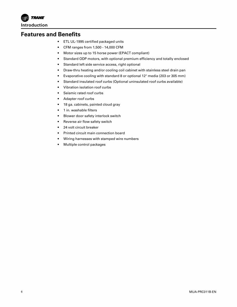
Features and Benefits• ETL UL-1995 certified packaged units
• CFM ranges from 1,500 - 14,000 CFM
• Motor sizes up to 15 horse power (EPACT compliant)
• Standard ODP motors, with optional premium efficiency and totally enclosed
• Standard left side service access, right optional
• Draw-thru heating and/or cooling coil cabinet with stainless steel drain pan
• Evaporative cooling with standard 8 or optional 12" media (203 or 305 mm)
• Standard insulated roof curbs (Optional uninsulated roof curbs available)
• Vibration isolation roof curbs
• Seismic rated roof curbs
• Adapter roof curbs
• 18 ga. cabinets, painted cloud gray
• 1 in. washable filters
• Blower door safety interlock switch
• Reverse air flow safety switch
• 24 volt circuit breaker
• Printed circuit main connection board
• Wiring harnesses with stamped wire numbers
• Multiple control packages
IInnttrroodduuccttiioonn

MUA-PRC011B-EN 7
Rooftop Air Handler Unit Number Description
A H A A 20 O A 0 F0 0 0 C F 1 0 5 H 0 P
1 2 3 4 5, 6 7 8 9 10,11 12 13 14 15 16 17 18 19 20 21
Digits 1, 2 — Unit Type
AH—Air Handling Unit
Digit 3 — Connection Side
A – Left-hand accessB – Right-hand access
Digit 4 — Development Sequence
A— First Generation
Digits 5, 6 — Unit Size
20— 1500 - 8000 Cfm40— 4000 - 14000 Cfm
Digit 7 — Venting Type
O—None
Digit 8 —Main Power Supply
A— 115/60/1B— 208/60/1C—230/60/1D— 208/60/3E— 230/60/3F— 460/60/3G— 575/60/3
Digit 9 — Gas Control Option
0—No gas control option
Digits 10, 11— Design Sequence
F0—Design Sequence
Digit 12— Fuel Type
0—No selection
Digit 13— Heat Exchanger Material
0—No selection
Digit 14 — Air Handler Arrangements
B—Blower (Standard)C—Blower (Standard) PlenumD—Blower (Standard) Evaporative CoolerE—Blower (Standard) Evaporative Cooler/PlenumG—Blower (High CFM)J—Blower (High CFM)/PlenumK—Blower (High CFM)/Coil CabinetL—Blower (High CFM)/Coil Cabinet/ Plenum
Digit 15 —Motor Selection
A— 1/2 HP. w/ContactorB— 3/4 HP. w/ContactorC— 1 HP. w/ContactorD—1-1/2 HP. w/ContactorE— 2 HP. w/ContactorF— 3 HP. w/ContactorG— 5 HP. w/ContactorH— 1/2 HP. w/Magnetic StarterJ—3/4 HP. w/Magnetic StarterK— 1 HP. w/Magnetic StarterL— 1-1/2 HP. w/Magnetic StarterN—2 HP. w/Magnetic StarterP—3 HP. w/Magnetic StarterQ— 5 HP. w/Magnetic StarterR—7-1/2 HP. w/Magnetic StarterT— 10 HP. w/Magnetic StarterU— 15 HP. w/Magnetic StarterV— 1 HP. w/VFDW—1–1/2 HP. w/VFDX—2 HP. w/VFDY— 3 HP. w/VFDZ— 5 HP. w/VFD1— 7–1/2 HP. w/ VFD2— 10 HP. w/VFD3— 15 HP. w/VFD
Digit 16 —Motor Speed and Starter
1—Single Speed ODP 1800 RPM2—Single Speed TEFC 1800 RPM3—Single Speed High Efficiency ODP 1800RPM4—Single Speed High Efficiency TEFC 1800RPM
Digit 17— Coil Options
O—No cooling coil selectionA—DX coil, 4 Row, Single CircuitB—DX coil, 4 Row, Dual CircuitC—DX coil, 6 Row, Single CircuitD—DX coil, 6 Row, Dual CircuitE—Chilled Water Coil, 4 Row, Single CircuitG—Chilled Water Coil, 6 Row, Dual Circuit
Digit 18— Air Inlet Configuration
1—Outside Air (OA) Horizontal Inlet2—Outside Air W/Air Hood, Horizontal Inlet3—Bottom Return Air (RA)4—Outside and Return Air (OA/RA)5—Outside and Return Air W/Air Hood
Digit 19— Air Control and DamperArrangements0—No selectionA—Outside Air 2 Pos. Motor / SRB—Return Air 2 Pos. Motor / SRC—OA/RA 2 Pos. / SRQ—OA/RA Mod. Mtr. w/CO2SensorE—OA/RA Mod. Mtr. w/Mixed Air Control /Min. Pot. / SRH—OA/RA Mod. Mtr. w/Mixed Air Control /SRK—OA/RA Mod. Mtr. w/Min. Pot. / SRM—OA/RA Mod. Mtr. w/Dry Bulb / Mixed AirControl / Min. Pot. /SRN—OA/RA Mod. Mtr. w/Enthalpy ControlledEconomizer / SRP—OA/RA Mod. Mtr. w/Pressure Control(Space Pressure)R—OA/RA Mod. Mtr. w/S-350-P ProportionalMixed Air Control/SRU—OA/RA MTR. W/External 0-10 VDC and4-20 mA Analog Input/SR (External Input)W—ASHRAE Cycle I (OA/RA 2 pos. w/warm-up stat/SRX—ASHRAE Cycle II (OA/RA ModW/Warm-up Stat/Mixed Air/min pot/SRY—ASHRAE Cycle III (OA/RA Mod. W/Warm-up Stat/Mixed Air/SRZ—Manual Dampers
Digit 20— California Shipment
0—Non-California Shipment1—California Shipment

8 MUA-PRC011B-EN
Digit 21—Miscellaneous Options
B— 12” Evaporative Media (Celdek)C—Moisture EliminatorsD—Horizontal ReturnE—Air Flow Proving SwitchF— FreezestatH—Return Air FirestatJ—Supply Air FirestatK—Manual Blower SwitchN—Double Wall ConstructionP— Low Leak DampersQ—Clogged Filter SwitchT—Status Indicator Lights (Elec Cabinet)W— 8" Evaporative Media (Glasdek)X— 12" Evaporative Media (Glasdek)Y—Ambient LockoutZ— Freezestat for Evap. Cooler0—No Filters Selected1—1" Washable (Standard) Filters2—2" Washable Filters3—2" Throwaway Filters4—1" Pleated Media Filters5—2" Pleated Media Filters
Digit 22 — VFD Accessories
1— Field Installed VFD
2— Factory Installed VFD
3—VFD Remote Keypad (Field Installed)
4—CO2 Sensor, 100% Outside Air
5—CO2 Sensor, Mixed Air
6— Pressure Sensor
7— 2-Speed VFD Relays
8— 3-Speed VFD Relays
9—VFD Enclosure
RRooooffttoopp AAiirr HHaannddlleerr UUnniitt NNuummbbeerr DDeessccrriippttiioonn

MUA-PRC011B-EN 9
Packaged Rooftop Arrangements
AAiirr HHaannddlleerr
Trane Packaged Rooftop Units are ETL certified to UL-1995 standard for heating cooling andventilating equipment.Units are available in one of 8 standard arrangements (Air HandlerArrangements, Model digit 14). Air Handler units (Unit Type “AH”) are suitable for commercial,institutional, and industrial applications where external system pressure losses are as high as 3"W.C.
Figure 1. Air Handler
Air Handler arrangements are divided into two classifications: Standard and High-CFM Blowertypes. The Standard Air Handler units (Air Handler Arrangement “B, C, D, E”) have a CFM rangeof 1,500 - 8,000 CFM (0.7 - 4.0 m3/s). The Standard Air Handler arrangement consists of a blowercabinet that houses dampers, filters, and blower in one cabinet; an optional Evaporative coolingunit with standard 8 or optional 12" media may also be included.
The High-CFM Air Handler Units (Air Handler Arrangement “G & J”) have a range of 3,000-14,000CFM (1.4 - 6.6m3/s). High CFM Air Handler units utilize a separate damper/filter cabinet with a “V”bank filter arrangement and a blower cabinet. Air Handler Arrangements “K & L” include anadditional cooling coil cabinet capable of up to 20 tons and a CFM range of 1,600 - 6,300 (0.8 -3.0m3/s). This coil cabinet may also be suitable for field installations of heating coils.
Both Standard and High-CFM Air Handler arrangements may also include a downturn supply airplenum, outside air intake hood with standard bird screen or optional moisture eliminators, anda roof curb. All arrangements are rail mounted.
For your safety and convenience all Trane Packaged Air Handler Units include a 24 Volt controlcircuit, 24 Volt in line circuit breaker, and blower door interlock switch with terminal block wiring.All wiring is processed at our factory as harness assemblies and each wire is permanentlystamped with it’s wire number.
All Cabinets are constructed of rugged 18 ga. material and painted cloud gray. The modulardesign of the cabinetry ensures reliability as well as serviceability with hinged access doors,water tight sealed seams, insulated blower filter, and plenum cabinets and down-rolled (hat type)rails that mount tightly over the roof curb.
AAiirr HHaannddlleerr AArrrraannggeemmeennttss
B = Air Handler (STANDARD)
C = Air Handler (STANDARD) / Plenum
D = Air Handler (STANDARD) / Evap. Cooling
E = Air Handler (STANDARD) / Evap. Cooling / Plenum
G = Air Handler (HIGH-CFM)
J = Air Handler (HIGH-CFM) / Plenum
10 MUA-PRC011B-EN
K =Air Handler (HIGH-CFM) / Coil Cabinet
L = Air Handler (HIGH-CFM) / Coil Cabinet / Plenum
PPaacckkaaggeedd RRooooffttoopp AArrrraannggeemmeennttss

MUA-PRC011B-EN 11
Packaged Rooftop Arrangement Reference
AAiirr HHaannddlleerrss,, UUnniitt TTyyppee ((AAHH))
* The maximum CFM for Air Handler Arrangements K and L is 6,300 (3.0 m3/s). A variablefrequency drive may be utilized for non-cooling air flow up to 14,000 CFM (6.6 m3/s).

12 MUA-PRC011B-EN
Accessory Pressure LossAir Handler Arrangements (B,C,D,E)Table 1. Pressure Loss (inches of water)

MUA-PRC011B-EN 13
Air Handler Arrangements (G,J,K,L)Table 2. Pressure Loss (inches of water)
NNoottee:: Refer to Tables 7 and 8 for DX Cooling Coil and Table 9 and 10 for Chilled Water PressureLosses (Air Handler Arrangements K, L).
AAcccceessssoorryy PPrreessssuurree LLoossss

14 MUA-PRC011B-EN
Air Handler PerformanceAir Handler Arrangement (B, C, D, E)
Table3.
TotalStaticPressure(Inchesofwater)
Capacity
CFM
.02
.04
.06
.08
11.2
1.4
1.6
RPM
BHP
RPM
BHP
RPM
BHP
RPM
BHP
RPM
BHP
RPM
BHP
RPM
BHP
RPM
BHP
20
1,500
395
.12
530
0.19
645
0.27
750
.35
845
0.44
930
0.54
1010
0.65
1085
0.76
2,000
435
.22
550
0.3
655
0.4
750
.49
835
0.59
915
0.7
995
0.81
1065
0.93
3,000
555
.61
630
0.71
710
0.83
790
.96
865
1.09
935
1.23
1000
1.37
1065
1.51
4,000
700
1.33
750
1.47
805
1.61
865
1.75
930
1.9
990
2.07
1045
2.25
1105
2.43
5,000
855
2.51
890
2.68
930
2.85
975
3.02
1020
3.19
1070
3.37
1120
3.55
1170
3.75
5,500
935
3.3
965
3.49
1000
3.67
1040
3.86
1080
4.05
1120
4.24
1165
4.43
1210
4.63
6,000
1015
4.25
1040
4.45
1075
4.65
1105
4.85
--
--
--
--
40
4,000
450
0.46
565
0.64
670
0.82
760
1.01
845
1.22
930
1.43
1005
1.66
1075
1.9
5,000
510
0.79
605
0.99
700
1.21
785
1.44
860
1.67
935
1.91
1005
2.16
1070
2.42
6,000
575
1.28
655
1.49
740
1.73
815
2885
2.28
955
2.56
1020
2.84
1085
3.12
7,000
650
1.95
715
2.19
785
2.44
855
2.73
920
3.04
985
3.36
1045
3.68
1105
4
8,000
725
2.83
780
3.1
840
3.38
905
3.67
965
3.99
1025
4.34
1080
4.71
--
Notes:
•RefertoTable1forAccessoryPressureLoss(es).
•Brakehorsepower(BHP)includesdrivelosses.
•"TotalExternalPressure(TSP)"isthesumoftheunits'InternalAccessorypressureloss(es)from
Table1plustheexternalstaticpressure.

MUA-PRC011B-EN 15
Table3.(continued).TotalStaticPressure(Inchesofwater)
Capacity
CFM
1.8
22.2
2.4
2.6
2.8
3
RPM
BHP
RPM
BHP
RPM
BHP
RPM
BHP
RPM
BHP
RPM
BHP
RPM
BHP
20
1,500
--
--
--
--
--
--
--
2,000
1135
1.06
--
--
--
--
--
--
3,000
1125
1.66
1180
1.81
1240
1.96
1295
2.12
1350
2.28
1405
2.45
1455
2.62
4,000
1160
2.61
1210
2.8
1260
2.98
1310
3.17
1360
3.35
1405
3.54
1455
3.74
5,000
1220
3.96
1265
4.18
1310
4.4
1360
4.63
1400
4.86
--
--
5,500
1255
4.84
--
--
--
--
--
--
6,000
--
--
--
--
--
--
--
40
4,000
1140
2.15
1205
2.42
--
--
--
--
--
5,000
1135
2.69
1200
2.97
--
--
--
--
--
6,000
1140
3.41
1200
3.71
1255
4.02
1315
4.34
1365
4.67
1420
5-
-
7,000
1160
4.33
1215
4.66
1270
4.99
--
--
--
--
8,000
--
--
--
--
--
--
--
Notes:
•RefertoTable1forAccessoryPressureLoss(es).
•Brakehorsepower(BHP)includesdrivelosses.
•"TotalExternalPressure(TSP)"isthesumoftheunits'InternalAccessorypressureloss(es)from
Table1plustheexternalstaticpressure.
AAiirr HHaannddlleerr PPeerrffoorrmmaannccee

16 MUA-PRC011B-EN
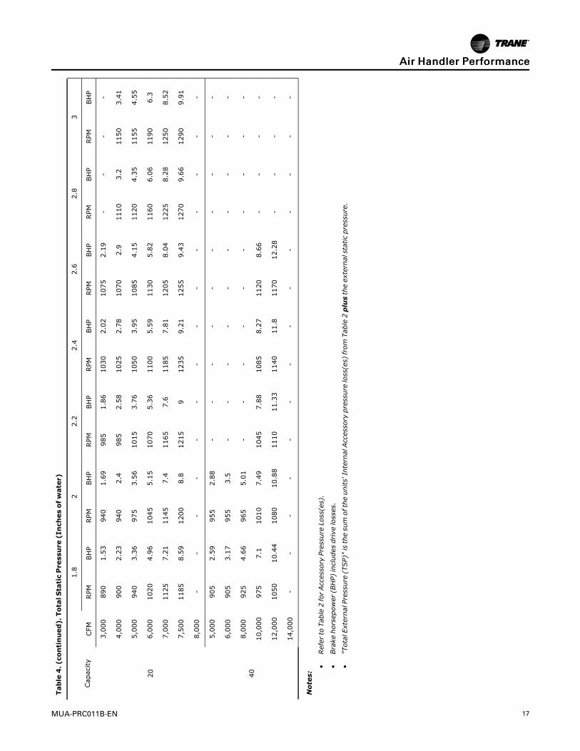
Rooftop Arrangement (G, J, K, L)The maximum CFM for Air Handler Arrangements K and L Cooling Coil is 6,300 (3.0 m3/s). Avariable frequency drive may be utilized for non-cooling air flow up to 14,000 CFM (6.6 m3/s).
Table4.
TotalStaticPressure(Inchesofwater)
Capacity
CFM
.02
.04
.06
.08
11.2
1.4
1.6
RPM
BHP
RPM
BHP
RPM
BHP
RPM
BHP
RPM
BHP
RPM
BHP
RPM
BHP
RPM
BHP
20
3,000
455
0.52
495
0.6
550
0.7
610
0.82
670
0.93
730
1.06
785
1.21
840
1.37
4,000
575
1.13
610
1.24
645
1.35
680
1.47
720
1.61
760
1.76
810
1.92
855
2.07
5,000
695
2.11
730
2.27
760
2.41
790
2.55
815
2.68
840
2.83
870
2.99
905
3.17
6,000
820
3.54
850
3.75
880
3.94
905
4.12
930
4.28
950
4.44
975
4.6
995
4.77
7,000
945
5.51
975
5.78
1000
6.02
1025
6.24
1050
6.45
1070
6.64
1090
6.83
1105
7.02
7,500
1005
6.74
1035
7.03
1060
7.3
1085
7.54
1110
7.77
1130
7.99
1150
8.19
1165
8.4
8,000
1070
8.13
1095
8.45
1125
8.74
1145
9.01
1170
9.27
1190
9.5
1210
9.73
1225
9.95
40
5,000
405
0.67
465
0.84
540
1.03
610
1.25
675
1.5
740
1.77
800
2.04
855
2.31
6,000
470
1.08
510
1.26
570
1.48
630
1.71
690
1.95
745
2.22
800
2.53
855
2.85
8,000
595
2.4
630
2.62
665
2.84
700
3.1
745
3.39
790
3.71
835
4.02
880
4.33
10,0-
00730
4.52
760
4.81
785
5.07
810
5.34
840
5.64
870
5.96
900
6.31
935
6.7
12,0-
00860
7.64
890
8.01
915
8.35
935
8.67
960
8.99
980
9.32
1000
9.66
1025
10.04
14,0-
00995
11.97
1020
12.41
1045
12.83
1065
13.22
1085
13.6
1105
13.97
1120
14.34
1140
14.73
Notes:
•RefertoTable2forAccessoryPressureLoss(es).
•Brakehorsepower(BHP)includesdrivelosses.
•"TotalExternalPressure(TSP)"isthesumoftheunits'InternalAccessorypressureloss(es)from
Table2plustheexternalstaticpressure.
AAiirr HHaannddlleerr PPeerrffoorrmmaannccee
MUA-PRC011B-EN 17
Table4.(continued).TotalStaticPressure(Inchesofwater)
Capacity
CFM
1.8
22.2
2.4
2.6
2.8
3
RPM
BHP
RPM
BHP
RPM
BHP
RPM
BHP
RPM
BHP
RPM
BHP
RPM
BHP
20
3,000
890
1.53
940
1.69
985
1.86
1030
2.02
1075
2.19
--
--
4,000
900
2.23
940
2.4
985
2.58
1025
2.78
1070
2.9
1110
3.2
1150
3.41
5,000
940
3.36
975
3.56
1015
3.76
1050
3.95
1085
4.15
1120
4.35
1155
4.55
6,000
1020
4.96
1045
5.15
1070
5.36
1100
5.59
1130
5.82
1160
6.06
1190
6.3
7,000
1125
7.21
1145
7.4
1165
7.6
1185
7.81
1205
8.04
1225
8.28
1250
8.52
7,500
1185
8.59
1200
8.8
1215
91235
9.21
1255
9.43
1270
9.66
1290
9.91
8,000
--
--
--
--
--
--
--
40
5,000
905
2.59
955
2.88
--
--
--
--
--
6,000
905
3.17
955
3.5
--
--
--
--
--
8,000
925
4.66
965
5.01
--
--
--
--
--
10,000
975
7.1
1010
7.49
1045
7.88
1085
8.27
1120
8.66
--
--
12,000
1050
10.44
1080
10.88
1110
11.33
1140
11.8
1170
12.28
--
--
14,000
--
--
--
--
--
--
--
Notes:
•RefertoTable2forAccessoryPressureLoss(es).
•Brakehorsepower(BHP)includesdrivelosses.
•"TotalExternalPressure(TSP)"isthesumoftheunits'InternalAccessorypressureloss(es)from
Table2plustheexternalstaticpressure.
AAiirr HHaannddlleerr PPeerrffoorrmmaannccee

18 MUA-PRC011B-EN
Dimensional DataAir Handler Arrangement B
Figure 2. Air Handler Arrangement B: Capacities 20 or 40 Unit Sizes (left hand service accessshown)
Air Handler Arrangement CFigure 3. Air Handler Arrangement C: Capacities 20 or 40 Unit Sizes (left hand service accessshown)
NNoottee:: Refer to Table 5 for tabulated dimensional data.
MUA-PRC011B-EN 19
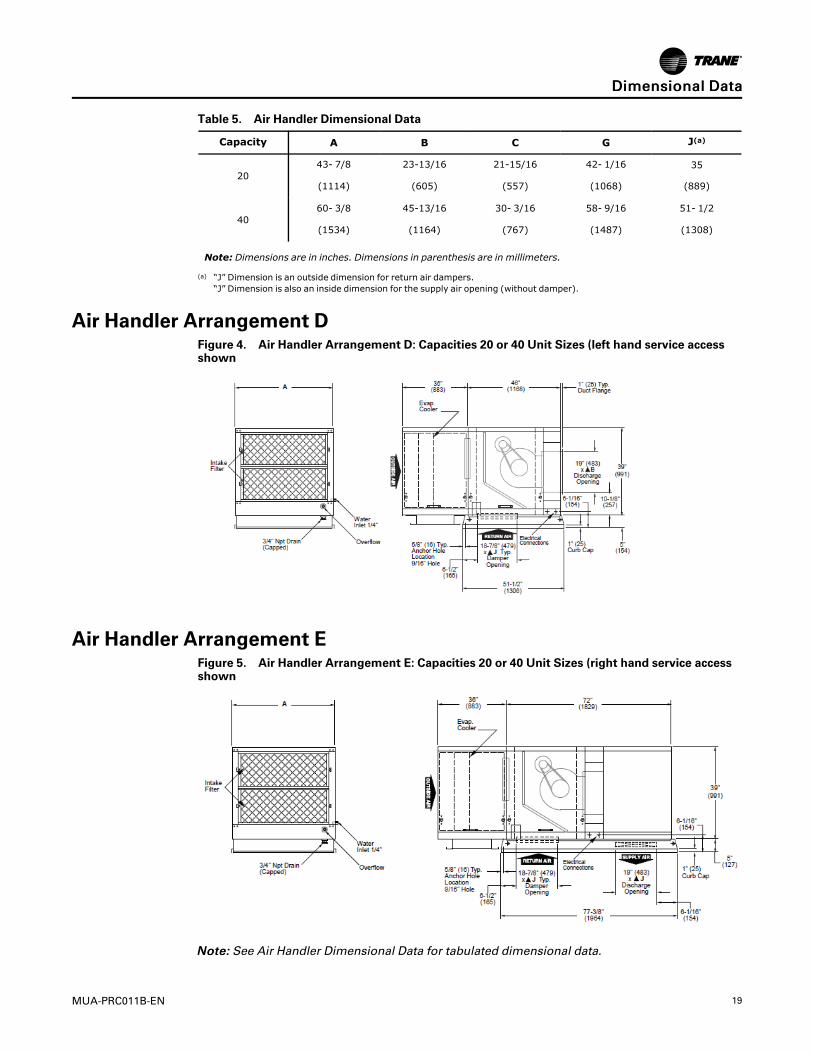
Table 5. Air Handler Dimensional Data
Capacity A B C G J(a)
2043- 7/8 23-13/16 21-15/16 42- 1/16 35
(1114) (605) (557) (1068) (889)
4060- 3/8 45-13/16 30- 3/16 58- 9/16 51- 1/2
(1534) (1164) (767) (1487) (1308)
Note: Dimensions are in inches. Dimensions in parenthesis are in millimeters.
(a) “J” Dimension is an outside dimension for return air dampers.“J” Dimension is also an inside dimension for the supply air opening (without damper).
Air Handler Arrangement DFigure 4. Air Handler Arrangement D: Capacities 20 or 40 Unit Sizes (left hand service accessshown
Air Handler Arrangement EFigure 5. Air Handler Arrangement E: Capacities 20 or 40 Unit Sizes (right hand service accessshown
NNoottee:: See Air Handler Dimensional Data for tabulated dimensional data.
DDiimmeennssiioonnaall DDaattaa
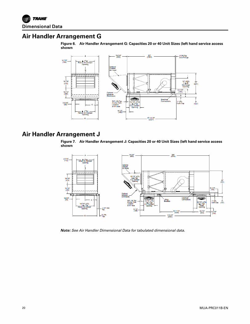
20 MUA-PRC011B-EN
Air Handler Arrangement GFigure 6. Air Handler Arrangement G: Capacities 20 or 40 Unit Sizes (left hand service accessshown
Air Handler Arrangement JFigure 7. Air Handler Arrangement J: Capacities 20 or 40 Unit Sizes (left hand service accessshown
NNoottee:: See Air Handler Dimensional Data for tabulated dimensional data.
DDiimmeennssiioonnaall DDaattaa

MUA-PRC011B-EN 21
Air Handler Arrangement KFigure 8. Air Handler Arrangement K: Capacities 20 or 40 Unit Sizes (left hand service accessshown
Air Handler Arrangement LFigure 9. Air Handler Arrangement L: Capacities 20 or 40 Unit Sizes (left hand service accessshown
NNoottee:: See Air Handler Dimensional Data for tabulated dimensional data.
DDiimmeennssiioonnaall DDaattaa

22 MUA-PRC011B-EN
Evaporative CoolingAir Handler Arrangements D, E
Evaporative Cooling is the simplest and most-cost effective cooling method without the use ofmechanical refrigeration. Trane Evaporative Cooling systems meet a wide range of commercial,industrial, and institutional heating and ventilating requirements. The Evaporative Cooler savesup to 80% on utility charges, requires little maintenance, and replaces exhausted, stale, indoor airwith cool, clean, filtered outdoor air.
Evaporative Coolers are also combined in Air Handler Unit Arrangements D and E. TheEvaporative Cooler will replace the need for a 100% Outside Air Inlet Hood. If an EvaporativeCooler is to be installed upstream of a duct furnace, a 409 stainless steel heat exchanger isrecommended.
Figure 10. Evaporative Cooler Module
Figure 11. Internal View Evaporative Cooler
MUA-PRC011B-EN 23
Standard Features• HHiigghh ccoooolliinngg eeffffiicciieennccyy:: Up to 88% saturation efficiency with standard 8" depth of CELdek®
media, and up to 92% saturation efficiency with optional 12" depth media; a 2" distributionpad is included to disperse water evenly. CELdek® media includes insoluble anti-rot salts andrigidifying saturants. The unique design of the CELdek pads optimizes air and water mixingfor maximum cooling.
• Optional 8" or 12" GLASdek® media is also available. See Accessory Options W and X.
• RReecciirrccuullaattiinngg ppuummpp:: Factory wired, sealed design, durable, thermally protected motor.Permanently lubricated bearings. Standard 115 Volt, 50/60 cycle. Optional 230V motor.Protective basket screen. U.L. recognized.
• HHeeaavvyy--dduuttyy ssttaaiinnlleessss sstteeeell wwaatteerr ttaannkk:: Stainless steel sump tank and water distributordesigned to resist rust, corrosion, and scaling.
• BBaallll vvaallvvee:: Single-entry ball valve regulates water flow using a 1/4 turn handle.
• BBlleeeedd--ooffff:: Prevents excessive concentration of minerals in sump water.
• FFllooaatt vvaallvvee:: Brass float valve and rod with plastic float. Maintains proper water level in sumpfor most efficient operation. Factory installed in cabinet.
• DDrraaiinn aanndd oovveerrffllooww:: Drain is capped. Overflow controlled by float level allowing slightcontinued overflow. Optional automatic fill and drain kit is available for field installation.
• WWaatteerr ddiissttrriibbuuttiioonn:: Copper water distributor tube for corrosion-free operation and lowmaintenance.
• IInnttaakkee ffiilltteerrss:: Removable intake filters of easy-to-clean 1" aluminummesh to remove insects,dust, and dirt from airflow.
• SSkkiidd rraaiillss:: With lifting and anchor holes. Optional adjustable platform curb assemblyavailable, shipped separately (see Roof Curb section).
Evaporative Cooling ModulesPerformance
Evaporative Cooling is most commonly used in areas where the relative humidity is low and thedry bulb temperatures are high. However, cooling through evaporation can be used in mostareas.
Evaporative cooling is best utilized whenever the wet bulb depression (difference between dryand wet bulb temperature) is a minimum of 15°. The efficiency of the Trane Evaporative Cooler isdetermined by a variety of factors: geographical location, application, air change requirements,sufficient water supply, air flow, and maintenance. In most instances, efficiency is expected to bebetween 77% and 88%. Heat gains in the distribution system will effect the final outputtemperature.
Use the psychometrics chart or actual humidity temperature readings to estimate the leaving drybulb temperature at the outlet of the Evaporative Cooler.
Example:
• Entering Dry Bulb: 95°F
• Entering Wet Bulb: 75°F
• Wet Bulb Depression (95°F - 75°F) = 20°F
• Effective Wet Bulb Depression (20°F x .85) = 17°F
• Leaving Dry Bulb Temperature (95°F -17° F) = 78°F
• Leaving Wet Bulb = Entering Wet Bulb = 75°F
EEvvaappoorraattiivvee CCoooolliinngg

24 MUA-PRC011B-EN
Figure 12. Psychometrics Chart
Selection MethodThe easiest method for selecting an evaporative cooler, is to first determine the required numberof air changes per minute:
1. Using the Zone chart, choose the geographical zone in which the unit is to be installed.Figure 13. Zone Chart
EEvvaappoorraattiivvee CCoooolliinngg

MUA-PRC011B-EN 25
2. Determine the internal load within the structure:NNoorrmmaall llooaadd:: structures with normal people loads, and without high internal heat gains.HHiigghh llooaadd:: Structures with high equipment loads (factories, laundromats, beauty salons,restaurant kitchens), and structures with high occupancy (nightclubs, arenas).
3. Determine whether the structure has normal or high heat gains:NNoorrmmaall ggaaiinn:: Structures that have insulated roofs, or are in shaded areas. Structures thathave two or more stories, or facing directions with no sun.HHiigghh ggaaiinn:: Structures that have uninsulated roofs, unshaded areas, or rooms that areexposed to sun.
4. Using table below, determine the required air changes per minute based on zone selectionand the type of heat load.
Table 6. Air Changes Per Minute
Zone
Type heat load 1 2 3 4
High load/high gain 3/4 1 1–1/3 2
High load/normal gain 1/2 3/4 1 1–1/3
Normal load/high gain 1/2 3/4 1 1–1/3
Normal load/normal gain 1/2 1/2 3/4 1
5. Determine the air quantity for the space chosen, by calculating the volume (L x W x H).Multiply this volume by the air changes per minute.
For example:
1. Structure dimensions: 25 L x 24 W x 10 H = 6000 Ft3
2. Exterior load type: Normal
3. Interior load type: Normal
4. Location: Dallas, Texas- Zone 3
5. Air changes per minute: 3/4Evaporative cooler requirements: 6000 Ft3 x 3/4 air change / minute- 4500 CFM required.
See Evaporative Cooler Performance Chart for unit size that would best apply.
Figure 14. Evaporative Cooling Unit
EEvvaappoorraattiivvee CCoooolliinngg

26 MUA-PRC011B-EN
Table 7. Performance and Dimensional Data
* Weights are for the Evaporative Cooler Module only.
CELdek®® Evaporative MediaThe Trane Evaporative Cooler utilizes high efficiency CELdek®media. CELdek is made from aspecial cellulose paper, impregnated with insoluble anti-rot salts and rigidifying saturants. Thecross fluted design of the pads induces highly-turbulent mixing of air and water for optimumheat and moisture transfer. Trane Evaporative coolers utilize 8" CELdek as standard equipment.Optional 12" CELdek, 8" and 12" GLASdek® are also available. A 2" distribution pad is used todisperse water evenly over the media.
Figure 15. Evaporative Cooler Efficiency and Air Pressure Drop
Cooling Coil OptionsAir Handler Arrangements (K, L)Coil Options Model Digit 17
Trane also offers coil cabinets and factory installed coils with our packaged air handlers. Asstandard equipment, we offer 4 or 6 row, single or dual circuit intertwine, DX (20 tons max.) orchilled water coils. Hot water and steam heating coils are also available. Trane coil cabinetsfeature draw through design to ensure even air flow across the coil face and a one piece 409
EEvvaappoorraattiivvee CCoooolliinngg
MUA-PRC011B-EN 27
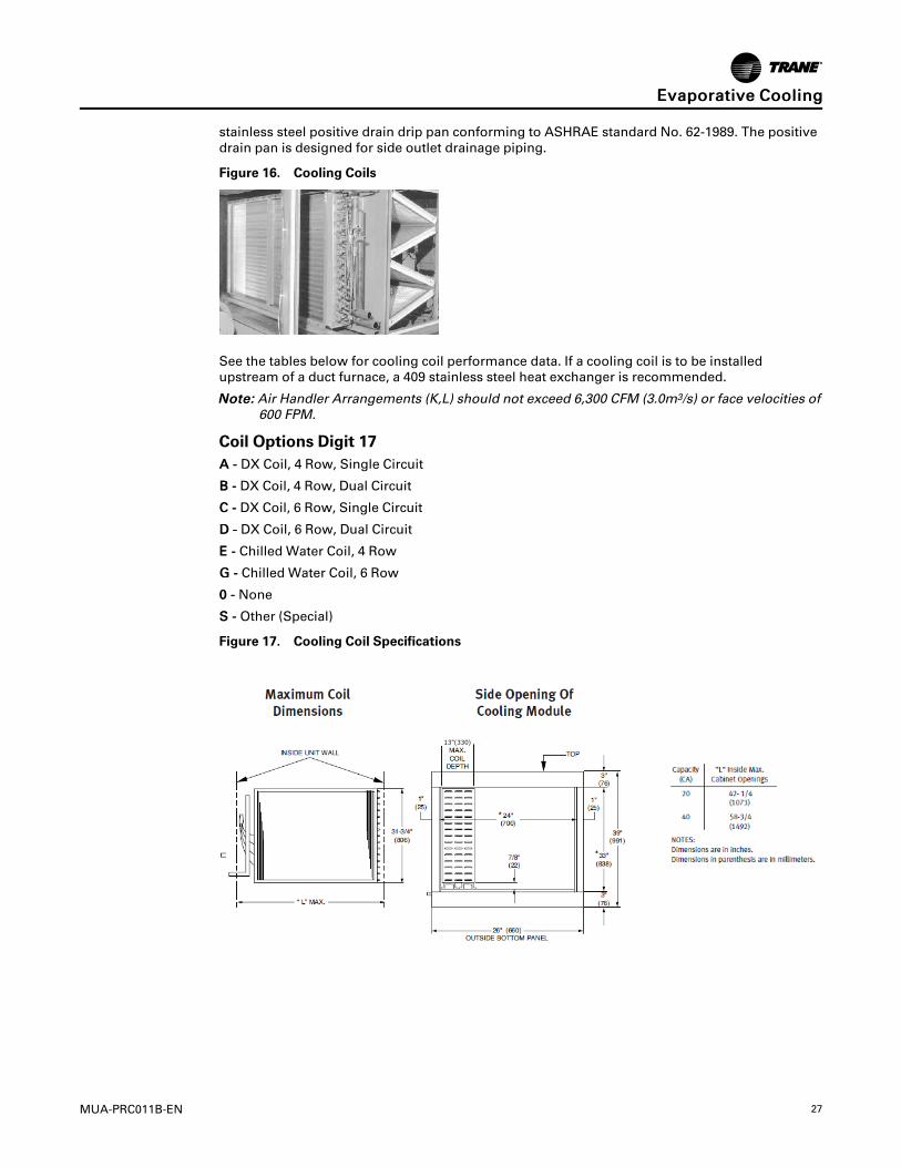
stainless steel positive drain drip pan conforming to ASHRAE standard No. 62-1989. The positivedrain pan is designed for side outlet drainage piping.
Figure 16. Cooling Coils
See the tables below for cooling coil performance data. If a cooling coil is to be installedupstream of a duct furnace, a 409 stainless steel heat exchanger is recommended.
NNoottee:: Air Handler Arrangements (K,L) should not exceed 6,300 CFM (3.0m3/s) or face velocities of600 FPM.
Coil Options Digit 17AA -- DX Coil, 4 Row, Single Circuit
BB -- DX Coil, 4 Row, Dual Circuit
CC -- DX Coil, 6 Row, Single Circuit
DD -- DX Coil, 6 Row, Dual Circuit
EE -- Chilled Water Coil, 4 Row
GG -- Chilled Water Coil, 6 Row
00 -- None
SS -- Other (Special)
Figure 17. Cooling Coil Specifications
EEvvaappoorraattiivvee CCoooolliinngg

28 MUA-PRC011B-EN
Air Handler Arrangements (K, L)DX Cooling Coil Performance Data (Ref. R-410A)Table 8. Capacity based on 80°F EDB, 67°F EWB, 45°F Sat. Suction, 100°F Liquid.
EEvvaappoorraattiivvee CCoooolliinngg

MUA-PRC011B-EN 29
Table 9. Capacity based on 95°F EDB, 74°F EWB, 45°F Sat. Suction, 100°F Liquid.
Conversions: 2119 SCFM = 1m3/s, 196.8FPM = 1m/s, 3.412 MBH = 1kW, (°F-32) 5/9 = °C, 1 IN.W.C. = 248.8 Pa, 0.4536 kg = 1 lb.
Notes:
• Data certified in accordance with ARI Standard 410.
• Weight listed is the total weight of the dry coil.
• Consult Customer Service Department for special coil requirements.
Air Handler Arrangements (K, L)Chilled Water Cooling Coil Performance DataTable 10. Capacity based on 80°F EDB, 67°F EWB, 45°F EWT, 70 GPM.
EEvvaappoorraattiivvee CCoooolliinngg
30 MUA-PRC011B-EN
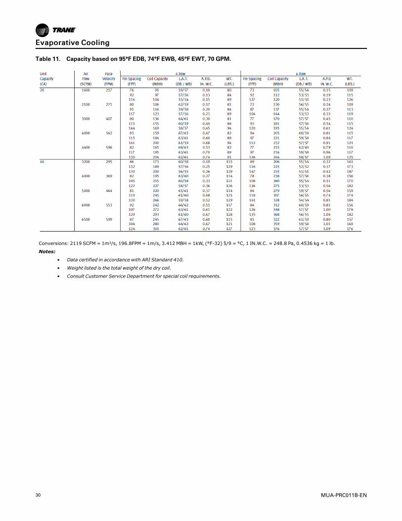
Table 11. Capacity based on 95°F EDB, 74°F EWB, 45°F EWT, 70 GPM.
Conversions: 2119 SCFM = 1m3/s, 196.8FPM = 1m/s, 3.412 MBH = 1kW, (°F-32) 5/9 = °C, 1 IN.W.C. = 248.8 Pa, 0.4536 kg = 1 lb.
Notes:
• Data certified in accordance with ARI Standard 410.
• Weight listed is the total weight of the dry coil.
• Consult Customer Service Department for special coil requirements.
EEvvaappoorraattiivvee CCoooolliinngg
MUA-PRC011B-EN 31
Component DescriptionsSupply Voltage
MMooddeell DDiiggiitt 88
The standard supply voltages are listed below.
A - 115 VAC, Single Phase, 60 Cycle
B- 208 VAC, Single Phase, 60 Cycle
C - 230 VAC, Single Phase, 60 Cycle
D - 208 VAC, Three Phase, 60 Cycle
E - 230 VAC, Three Phase, 60 Cycle
F - 460 VAC, Three Phase, 60 Cycle
G - 575 VAC, Three Phase, 60 Cycle
Motor TypeMMooddeell DDiiggiitt 1166
Blower Motors are available in Open Drip Proof, Totally Enclosed, Premium Efficiency Open DripProof and Premium Efficiency Totally Enclosed. Motors are ball bearing type with a resilient baseand NEMA frame sizes from 48 to 256T. Windings are Class “B”, 1800 RPM with service factors of1/2–3/4 HP = 1.25 and 1–15 HP = 1.15. Motors are in compliance with the Energy Policy Act(EPACT) of 1992 and any of its latest editions.
1 - Open Drip Proof Motor (ODP)
2 - Totally Enclosed (TEFC)
3 - Premium Efficiency Open Drip Proof (PEODP)
4 - Premium Efficiency Totally Enclosed (PETE)
Motor SizeMMooddeell DDiiggiitt 1155
Motors are available from 1/2 to 15 HP. Thermal Protection is automatic for most motors up to 5HP., a Magnetic Starter with IEC (International Electrotechnical Commission) type over currentprotection must be used for motors without automatic thermal protection and motors above 5HP.
Variable Frequency Drive (VFD) operating range: 14°F to 130°F. For temperatures below 14°F,VFD must be factory-installed within the VFD Enclosure accessory (Model Digit 22, option 9), orfield-mounted indoors.
A - 1/2 HP. with Contactor
B - 3/4 HP. with Contactor
C - 1 HP. with Contactor
D - 1 1/2 HP. with Contactor
E - 2 HP. with Contactor
F- 3 HP. with Contactor
G - 5 HP. with Contactor
H - 1/2 HP. with Magnetic Starter and IEC over current protection
J - 3/4 HP. with Magnetic Starter and IEC over current protection
K - 1 HP. with Magnetic Starter and IEC over current protection
L- 1 1/2 HP. with Magnetic Starter and IEC over current protection
N - 2 HP. with Magnetic Starter and IEC over current protection

32 MUA-PRC011B-EN
P - 3 HP. with Magnetic Starter and IEC over current protection
Q - 5 HP. with Magnetic Starter and IEC over current protection
R - 7 1/2 HP. with Magnetic Starter and IEC over current protection
T - 10 HP. with Magnetic Starter and IEC over current protection
U - 15 HP. with Magnetic Starter and IEC over current protection
V - 1 HP. with Variable Frequency Drive
W- 1 1/2 HP. with Variable Frequency Drive
X - 2 HP. with Variable Frequency Drive
Y- 3 HP. with Variable Frequency Drive
Z- 5 HP. with Variable Frequency Drive
1- 7 1/2 HP. with Variable Frequency Drive
2- 10 HP. with Variable Frequency Drive
3- 15 HP. with Variable Frequency Drive
Air Inlet ConfigurationMMooddeell DDiiggiitt 1188
The Air Inlet Configuration defines the entering air openings for Trane Engineered Products. Thisitem does not include dampers and must match the required opening for Air Control and DamperArrangement. A horizontal return air feature is offered on air inlet configurations 4 and 5. Refer toDigit 21 Accessory Option D.
Figure 18. Air Inlet Configuration
1 - Horizontal Inlet (100% Outside Air or 100% Return Air)
2 - Horizontal Inlet (100% Outside Air or 100% Return Air) with Intake Hood
3 - Bottom Return Air Opening
4 - Outside and Return Air Opening
5 - Outside and Return Air Opening with Intake Hood
* Horizontal Outside and Return Air Openings. See Accessories Section Model Digit 21, Option D.
Air Control and Damper ArrangementMMooddeell DDiiggiitt 1199
A - Outside air damper with 2 Position spring return damper motor. Outside air damper opens upon energizingthe unit blower motor.
B - Return air damper with 2 Position spring return damper motor. Return air damper opens upon energizing theunit blower motor.
C - Outside and return air interlocked dampers with 2 position spring return damper motor. Outside air damperopens and return air damper closes upon energizing the unit blower motor.
E - Outside and return air interlocked dampers with modulating spring return damper motor, mixed airtemperature control, and minimum position potentiometer. Outside and return air dampers modulate inresponse to the mixed air temperature setpoint and allow minimum outside air setting. When de-energizedoutside air dampers close and return air dampers open.
CCoommppoonneenntt DDeessccrriippttiioonnss
MUA-PRC011B-EN 33
H - Outside and return air interlocked dampers with modulating spring return damper motor and mixed airtemperature control. Outside and return air dampers modulate in response to the mixed air temperaturesetpoint. When de-energized outside air dampers close and return air dampers open.
K - Outside and return air interlocked dampers with modulating spring return damper motor and positioningpotentiometer. Outside and return air dampers open and close with respect to the setting of the positioningpotentiometer. When de-energized outside air dampers close and return air dampers open.
M - Outside and return air interlocked dampers with modulating spring return damper motor. Mixed airtemperature control, minimum position potentiometer, and dry bulb economizer. Outside and return airdampers modulate in response to the mixed air temperature setpoint and allow minimum outside air setting.Dampers respond to the economizer when the outside air temperature is within the set point range byopening the outside and closing the return air damper to achieve free cooling effect. When de-energizedoutside air dampers close and return air dampers open.
N - Outside and return air interlocked dampers with modulating spring return damper motor and enthalpycontrolled economizer outside and return air dampers modulate in response to the heat content of sensedmixed air. The air mixture is optimized to provide inlet air with the lowest possible load characteristics in bothheating and cooling modes. When de-energized outside air dampers close and return air dampers open.
P - Outside and return air interlocked dampers with modulating damper motor and atmospheric pressure sensor.Outside and return air dampers modulate in response to sensed building pressure, typically maintaining aslightly positive building pressure in order to reduce heat loss due to infiltration.
Q - Outside and return air interlocked dampers with modulating damper motor and CO2 (carbon dioxide) monitor.Outside and return air dampers modulate in response to the CO2 monitor set point. Monitor is located in thereturn air stream. On a rise in CO2 level, the outside damper modulates open and the return air dampercloses. A decrease in CO2 level modulates the outside air damper closed and opens the return air damper.When the unit is de-energized, the damper motor will close the outside air damper and open the return airdamper. Equipped with one normally open contact for alarm light or bell to guard against times of sustainedhigh CO2 levels. CO2 monitor is shipped loose for field installation.
R - Outside and return air interlocked dampers with modulating spring return damper motor and S350proportional mixed air control. Outside and return air dampers modulate in response to the mixed airtemperature setpoint, and allow minimum outside air setting. When de-energized outside air dampers closeand return air dampers open.
U- Outside and return air interlocked dampers with modulating spring return damper motor and 0-10VDC or 4-20mA input. Requires an external input signal from a Direct Digital Controller (DDC). Provides proportionalcontrol from a building management system or electronic controller based on programmed parameters.When de-energized outside air dampers close and return air dampers open.
W- ASHRAE Cycle I Outside and return dampers with two position spring return damper motor and warm-upthermostat. When energized dampers open in response to the warm-up thermostat preventing cold air starts.
X- ASHRAE Cycle II Outside and return air interlocked dampers with modulating spring return damper motor.Mixed air temperature control, minimum position potentiometer, and warm-up thermostat. Outside andreturn air dampers modulate in response to the mixed air temperature setpoint and allow minimum outsideair setting once the warm-up thermostat has been satisfied. When de-energized outside air dampers closeand return air dampers open.
Y- ASHRAE Cycle III Outside and return air interlocked dampers with modulating spring return damper motor.Mixed air temperature control and warm-up thermostat. Outside and return air dampers modulate inresponse to the mixed air temperature setpoint once the warmup thermostat has been satisfied. When de-energized outside air dampers close and return air dampers open.
Z - Manual outside and return air dampers. Dampers are locked into position utilizing a manual quadrant for fieldadjustment.
CCoommppoonneenntt DDeessccrriippttiioonnss
34 MUA-PRC011B-EN
AccessoriesMMooddeell DDiiggiitt 2211
Mechanical AccessoriesC- Moisture eliminators
Use in place of the bird screen with an outside air hood. The metal wire filter is designed to collect waterdroplets/mists and drain them to the bottom of the filter. This item includes an electrically interlockeddifferential pressure switch with indicator lamp in case of blockage.
D - Horizontal returnLocates the return air opening under the outside air opening location. For units with both outside air andreturn air openings Model Digit 18(4 or 5). Includes moisture eliminators as standard when 5 is chosen.
P- Low Leak DamperThis item includes vinyl blade edge seals with a standard opposed blade galvanized steel damper andneoprene nylon bushings. For outside side air inlet only.
Filters1- 1" Washable Filters (Standard)
2- 2" Washable Filters
3- 2" Throwaway Filters
4- 1" High Efficiency 30% Filters (MERV 8)
5- 2" High Efficiency 30% Filters (MERV 8)
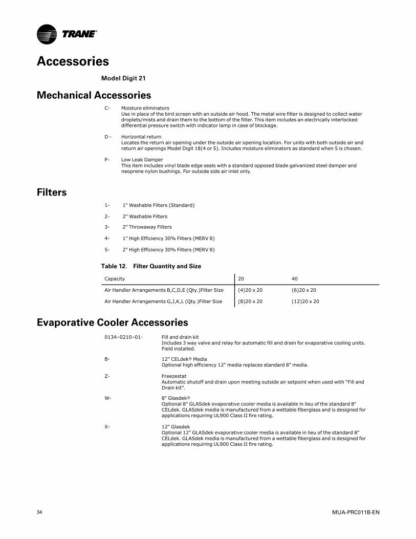
Table 12. Filter Quantity and Size
Capacity 20 40
Air Handler Arrangements B,C,D,E (Qty.)Filter Size (4)20 x 20 (6)20 x 20
Air Handler Arrangements G,J,K,L (Qty.)Filter Size (8)20 x 20 (12)20 x 20
Evaporative Cooler Accessories0134–0210–01- Fill and drain kit
Includes 3 way valve and relay for automatic fill and drain for evaporative cooling units.Field installed.
B- 12" CELdek® MediaOptional high efficiency 12" media replaces standard 8" media.
Z- FreezestatAutomatic shutoff and drain upon meeting outside air setpoint when used with “Fill andDrain kit”.
W- 8" Glasdek®Optional 8" GLASdek evaporative cooler media is available in lieu of the standard 8"CELdek. GLASdek media is manufactured from a wettable fiberglass and is designed forapplications requiring UL900 Class II fire rating.
X- 12" GlasdekOptional 12" GLASdek evaporative cooler media is available in lieu of the standard 8"CELdek. GLASdek media is manufactured from a wettable fiberglass and is designed forapplications requiring UL900 Class II fire rating.

MUA-PRC011B-EN 35
Time Clocks0134-0201-02- 7 day time clock
Provides single pole double throw (SPDT) relay output at setpoint time with maximum 6 setpoints per day, field installed.
0134-0201-03- 24 hour time clockProvides single pole double throw (SPDT) relay output at setting time with maximum 12 setpoints per day, field installed.
Electrical AccessoriesQ- Clogged filter switch
Factory installed differential pressure switch with clogged filter indicator lamp located in themain electrical cabinet.
0134-0204-01- Ground fault convenience outlet 115VACG.F.I. outlet with manual reset in a weather resistant enclosure, field installed.
0134-0201-01- Remote control panelWall mounted and distinctively styled the “Trane Remote Panel” offers 6 LED status lampswith System On/Off, Fan Auto/On, Heat Auto/Off, Cool Auto/Off, Auxiliary On/Off switchingand Modulating damper potentiometer mounting. Designed for E-Z Installation with plug-interminal block wiring and wall mounting bracket. Field installed. (Auxiliary On/OFF may beused with Evaporative Cooler Fill & Drain Kit or exhaust fan) (6-1/4" W x 3-3/4" H x 1-3/8"D)
K- Manual blower switchFactory installed in the electrical cabinet to provide manual blower operation (On/Auto).
Figure 19. Remote Control Panel
Duct and Room Thermostats0134-0207-03 - One stage duct thermostat
Field installed, single pole double throw switching. 55°-175°F set point range. (2" W x5-5/8" H x 2-7/16" D)
0134-02006 - Two stage duct thermostatField installed, single pole double throw switching. 55°-175°F set point range. (2" W x5-5/8" H x 2-7/16" D)
0134-THT02569-01 - T87K thermostat with subbaseSingle stage heating thermostat. Subbase includes fan switching relay. Standard roundstyling suitable for any decor. 40°-90°F range. Mercury free.
0134-THT02569G-01 - T87K thermostat with subbase and guardSame features as 0134-THT02569-01 except a tamper proof guard is included.
0350-0015-02 - T83N thermostat with subbaseSingle stage heating thermostat with fan switch. 50°-90°F range. (2-3/8" W x 4-3/4" Hx 1-1/2" D) Mercury free.
AAcccceessssoorriieess

36 MUA-PRC011B-EN
0134-THT02568-01 - TB8220U programmable commercial touchscreen thermostatProvides 7 day programmability for up to two stages of heating and two stages ofcooling. Includes a terminal to enable an economizer or control a lighting panel whenused as a time of day relay. Temperature ranges: Heating 40°-90°F, Cooling 50-99°F (6"W x 3-3/4" H x 1-3/8" D) Mercury free.
0134-THT02532-01 - TH5220D two stage thermostatTwo stage heating and two stage cooling with system and fan switching and built in 10°Fheating/cooling differential. Includes fan relay. Temperature ranges: Heating 40°-90°F,Cooling 50°-99°F (5-13/16" W x 3-9/16" H x 1-1/2" D) Mercury free.
0134-0207-07 - TG511 locking thermostat coverUniversal locking thermostat cover for use with all thermostats listed.
Figure 20. T83N Thermostat with Subbase
Figure 21. TB8220U Programmable Commercial Touchscreen Thermostat
AAcccceessssoorriieess
MUA-PRC011B-EN 37
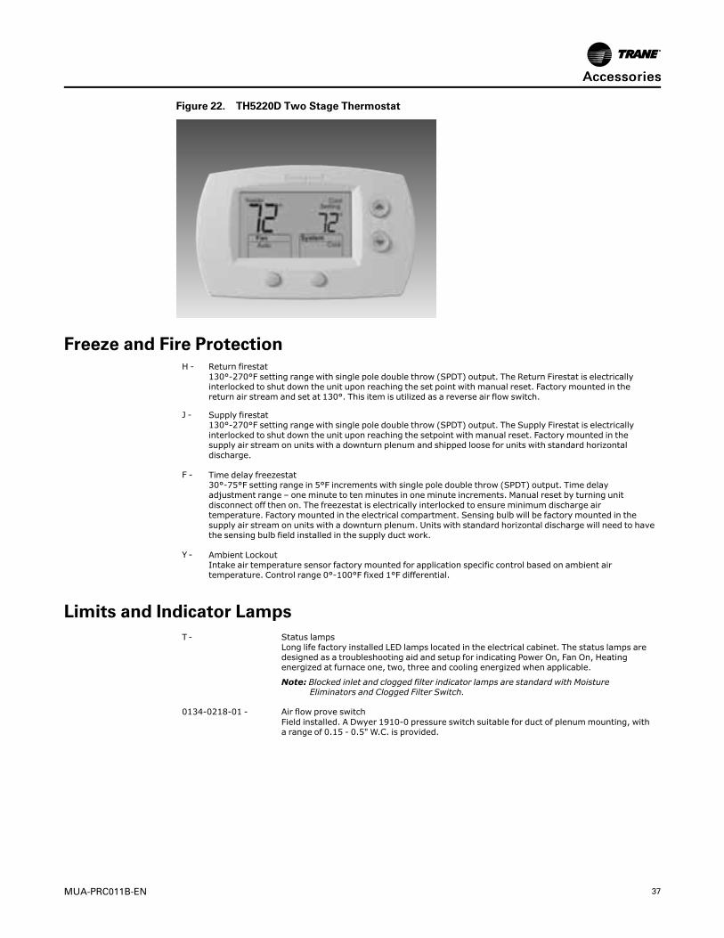
Figure 22. TH5220D Two Stage Thermostat
Freeze and Fire ProtectionH - Return firestat
130°-270°F setting range with single pole double throw (SPDT) output. The Return Firestat is electricallyinterlocked to shut down the unit upon reaching the set point with manual reset. Factory mounted in thereturn air stream and set at 130°. This item is utilized as a reverse air flow switch.
J - Supply firestat130°-270°F setting range with single pole double throw (SPDT) output. The Supply Firestat is electricallyinterlocked to shut down the unit upon reaching the setpoint with manual reset. Factory mounted in thesupply air stream on units with a downturn plenum and shipped loose for units with standard horizontaldischarge.
F - Time delay freezestat30°-75°F setting range in 5°F increments with single pole double throw (SPDT) output. Time delayadjustment range – one minute to ten minutes in one minute increments. Manual reset by turning unitdisconnect off then on. The freezestat is electrically interlocked to ensure minimum discharge airtemperature. Factory mounted in the electrical compartment. Sensing bulb will be factory mounted in thesupply air stream on units with a downturn plenum. Units with standard horizontal discharge will need to havethe sensing bulb field installed in the supply duct work.
Y - Ambient LockoutIntake air temperature sensor factory mounted for application specific control based on ambient airtemperature. Control range 0°-100°F fixed 1°F differential.
Limits and Indicator LampsT - Status lamps
Long life factory installed LED lamps located in the electrical cabinet. The status lamps aredesigned as a troubleshooting aid and setup for indicating Power On, Fan On, Heatingenergized at furnace one, two, three and cooling energized when applicable.
Note: Blocked inlet and clogged filter indicator lamps are standard with MoistureEliminators and Clogged Filter Switch.
0134-0218-01 - Air flow prove switchField installed. A Dwyer 1910-0 pressure switch suitable for duct of plenummounting, witha range of 0.15 - 0.5" W.C. is provided.
AAcccceessssoorriieess

38 MUA-PRC011B-EN
Interlock Relays0134-0303-01 - 24 volt DPDTrelay
Plug-in, Type 2, Form C relay with 24 volt coil and double pole double throw 10 amp.contacts. This relay plugs in to the Main Connection PC board in the electrical cabinet.Included with Packaged units including an evaporative cooler and outside return airdampers or may be utilized as an exhaust fan interlock. When energized at terminal “K2” ofthe main connection board, the blower is engaged and outside air dampers are opened to100% position. Factory installed.
0134-0301-01 - 24/115 volt SPDTrelayThis relay has selectable coil voltage of 24 or 115 volts and single pole double throw 10amp contacts with LED On indicator lamp. Relay is utilized as an auxiliary relay when 24volt DPDTrelay does not apply for exhaust fan interlock or digital interface with an externalcontrol. Factory mounted and wired when applicable.
Note: Shipped loose unless otherwise specified.
0134-0302-01 - 24/115/230 volt DPDTrelayThis relay has selectable coil voltage of 24, 115 or 230 volts and double pole double throw10 amp contacts. Relay is utilized as an auxiliary relay for general purpose duty. Factorymounted and wired when applicable.
Note: Shipped loose unless otherwise specified.
0134-0304-01 - 24 volt 4PDTrelayThis relay has a coil voltage of 24 volts and four pole double throw 10 amp contacts. Relayis included as standard for packaged units with an Evaporative Cooler or Coil Cabinet andmay be utilized as an auxiliary relay for general purpose duty. Factory mounted and wiredwhen applicable.
Note: Shipped loose unless otherwise specified.
Figure 23. Interlock Relays - 24/115 Volt SPDT Relay and 24/115/230 Volt DPDT Relay
Disconnect Switches (NEMA-3R)0134-0202-06 (115-230V, 1 Ph.)0134-0202-07 (208-230V, 3 Ph.)0134-0202-08 (460-575V, 3 Ph.)
30 Amp. fused disconnectField installed.
0134-0202-01 (115-230V, 1 Ph.)0134-0202-02 (208-230V, 3 Ph.)0134-0202-03 (460-575V, 3 Ph.)
30 Amp. non-fused disconnectField installed.
0134-0202-09 (208-230V, 3 Ph.)0134-0202-10 (460-575V, 3 Ph.)
60 Amp. fused disconnectField installed.
0134-0202-04 (208-230V, 3 Ph.)0134-0202-05 (460-575V, 3 Ph.)
60 Amp. non-fused disconnectField installed.
AAcccceessssoorriieess
MUA-PRC011B-EN 39
Convenience Accessories7 - Through-the-base utility penetrations
Through the base utility penetrations allows the electric and coil connections to be passed through base andcurb of the unit. This results in a reduction in the number of roof penetrations, thus enhancing the integrity ofthe roofing materials. roofing materials. Electrical and coil connections will enter the unit in the blowercabinet.
6 - Service convenience packageIncludes a factory mounted switch type fused disconnect and GFI convenience outlet mounted behind ahinged access door on the units’ blower section. Both items are accessible from the outside of the unit via aweather proof hinged access door. This accessory also includes Through-The-Base Utility Penetrations.
N - Double wall cabinet constructionConsists of a 24 gauge inner liner wall with 1" 1-1/2 LB density insulation. Available on the filter / damper,blower, coil, and plenum cabinets only.
VFD OptionsMMooddeell DDiiggiitt 2222
1 - Field installed VFDReplaces the Magnetic Starter and provides soft start operation, prolonging the life of blowers and bearings aswell as reducing start up noise. All VFD’s are UL approved and are manufactured with a NEMA 1 plenum ratedenclosure. Field installed VFD is standard for motor size selections 1-8. For a factory installed option, see VFDOption 2.
2 - Factory installed VFDUL approved with a NEMA 1 plenum rated enclosure, is mounted in the unit blower cabinet with a remoteprogramming keypad located in the electrical cabinet.
3 - Remote keypadAllows operation of drive up to 100 ft. (30 Meters) from the drive and duplicates the functionality of thedrive’s local keypad. Shipped loose for field installation.
4 - CO2 Sensor 100%Outside AirFactory supplied, field installed CO2 monitor range 0 to 2,000 ppm, adjustable, for mounting in occupiedspace. Upon rise in CO2 above field programmed set point, 0-10VDC or 4-20 mA signal will be sent from CO2sensor to VFD to modulate air flow between minimum set point and maximum CFM.
5 - CO2 Sensor Mixed AirFactory supplied, field installed CO2 monitor range 0 to 2,000 ppm, adjustable, for mounting in return airduct. Upon rise in CO2 above field programmed set point, signal will drive return air damper to 100% closedand outside air damper to 100% open. 0-10VDC or 4-20 mA signal will be sent from CO2 sensor to VFD tomodulate air flow between minimum set point and maximum CFM.
6 - Pressure SensorFactory supplied, field installed pressure control, range -0.1 to +0.1" W.C. VFD will modulate motor speedbased on 4-20 mA signal from pressure control sensor mounted in space to maintain field programmed setpoint.
7 - 2-Speed VFD RelaysFactory installed relays provided to energize second speed setting. Relay coil will accept 24V, 115V and 230V.
8 - 3-Speed VFD RelaysFactory installed relays provided to energize second and third speed settings. Relay coil will accept 24V, 115Vand 230V.
9 - A factory installed NEMA-3R enclosure will be provided to protect the VFD in outdoor applications. Enclosureincludes a small electric heater and vent fan to protect the VFD in ambient temperatures of -30 - 115°F (-34 -46°C).
Note: Enclosure only available when factory installed VFD is selected.
AAcccceessssoorriieess
40 MUA-PRC011B-EN
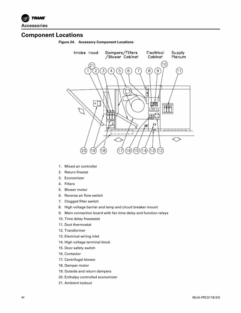
Component LocationsFigure 24. Accessory Component Locations
1. Mixed air controller
2. Return firestat
3. Economizer
4. Filters
5. Blower motor
6. Reverse air flow switch
7. Clogged filter switch
8. High voltage barrier and lamp and circuit breaker mount
9. Main connection board with fan time delay and function relays
10. Time delay freezestat
11. Duct thermostat
12. Transformer
13. Electrical wiring inlet
14. High voltage terminal block
15. Door safety switch
16. Contactor
17. Centrifugal blower
18. Damper motor
19. Outside and return dampers
20. Enthalpy controlled economizer
21. Ambient lockout
AAcccceessssoorriieess

MUA-PRC011B-EN 41
Roof Curb KitsStandard Roof Curb Kits
Trane roof curbs are available in various types depending upon your application needs. All curbskits are knocked down for field assembly and are shipped separately. Curbs are typicallyavailable on a short lead time basis allowing the installer to set the curb in place prior toreceiving the rooftop unit.
Standard curbs are 12" high. Factoring in the 4" unit base rail, overall height to the bottom of therooftop unit is actually 16". All standard curbs are fully factory insulated.
Uninsulated Roof Curb KitsTrane uninsulated roof curb kits are identical to the standard kits, with the exception of theinsulation.
Vibration Isolation and Seismic CurbsVibration isolation curbs are utilized in installations where slight rooftop vibration or noise is aconcern. These curbs incorporate adjustable spring isolators into the roof curb which arespecifically engineered and positioned to accommodate the rooftop unit.
Seismic curbs are designed to meet all local and federal building code seismic requirements byproviding a reinforced curb constructed to allow rooftop units to be properly secured to themounting structure and will withstand the regional seismic load.
Contact Trane for further information, including part numbers and pricing.
Adaptor CurbsAdaptor curbs are designed for retrofit installations. With the use of an adaptor curb it is notnecessary to remove the existing curb, thus eliminating extensive rooftop work, time andassociated construction costs. Provide us with the existing unit model number and curbdimensions and a custom adaptor curb will be supplied to accommodate the new rooftop unit.
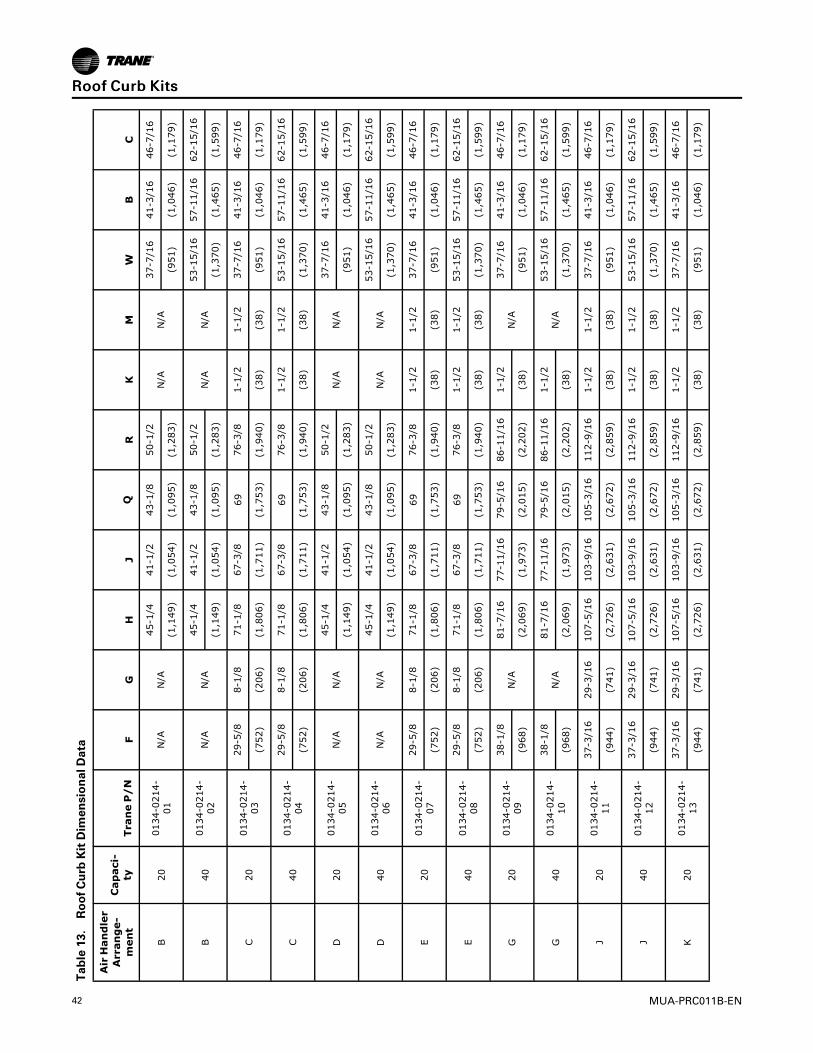
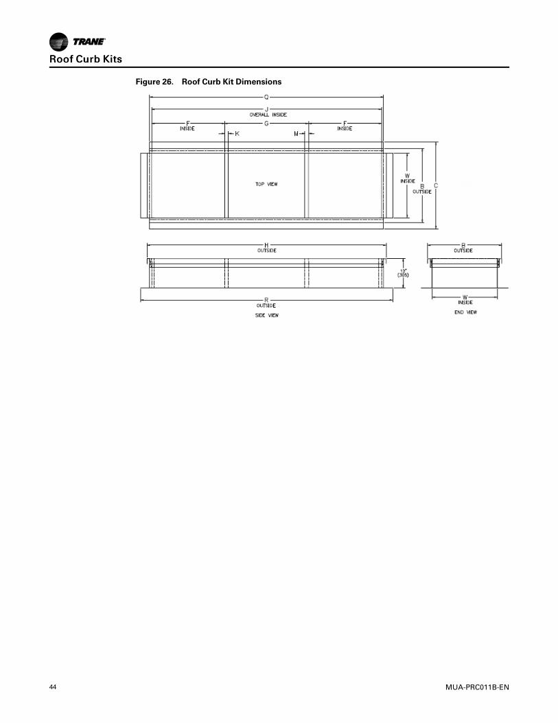
Dimensional DataFigure 25. Roof Curb Kit Dimensions
42 MUA-PRC011B-EN
Table13.RoofCurbKitDimensionalData
AirHandler
Arrange-
ment
Capaci-
tyTraneP/N
FG
HJ
QR
KM
WB
C
B20
0134-0214-
01N/A
N/A
45-1/4
41-1/2
43-1/8
50-1/2
N/A
N/A
37-7/16
41-3/16
46-7/16
(1,149)
(1,054)
(1,095)
(1,283)
(951)
(1,046)
(1,179)
B40
0134-0214-
02N/A
N/A
45-1/4
41-1/2
43-1/8
50-1/2
N/A
N/A
53-15/16
57-11/16
62-15/16
(1,149)
(1,054)
(1,095)
(1,283)
(1,370)
(1,465)
(1,599)
C20
0134-0214-
03
29-5/8
8-1/8
71-1/8
67-3/8
6976-3/8
1-1/2
1-1/2
37-7/16
41-3/16
46-7/16
(752)
(206)
(1,806)
(1,711)
(1,753)
(1,940)
(38)
(38)
(951)
(1,046)
(1,179)
C40
0134-0214-
04
29-5/8
8-1/8
71-1/8
67-3/8
6976-3/8
1-1/2
1-1/2
53-15/16
57-11/16
62-15/16
(752)
(206)
(1,806)
(1,711)
(1,753)
(1,940)
(38)
(38)
(1,370)
(1,465)
(1,599)
D20
0134-0214-
05N/A
N/A
45-1/4
41-1/2
43-1/8
50-1/2
N/A
N/A
37-7/16
41-3/16
46-7/16
(1,149)
(1,054)
(1,095)
(1,283)
(951)
(1,046)
(1,179)
D40
0134-0214-
06N/A
N/A
45-1/4
41-1/2
43-1/8
50-1/2
N/A
N/A
53-15/16
57-11/16
62-15/16
(1,149)
(1,054)
(1,095)
(1,283)
(1,370)
(1,465)
(1,599)
E20
0134-0214-
07
29-5/8
8-1/8
71-1/8
67-3/8
6976-3/8
1-1/2
1-1/2
37-7/16
41-3/16
46-7/16
(752)
(206)
(1,806)
(1,711)
(1,753)
(1,940)
(38)
(38)
(951)
(1,046)
(1,179)
E40
0134-0214-
08
29-5/8
8-1/8
71-1/8
67-3/8
6976-3/8
1-1/2
1-1/2
53-15/16
57-11/16
62-15/16
(752)
(206)
(1,806)
(1,711)
(1,753)
(1,940)
(38)
(38)
(1,370)
(1,465)
(1,599)
G20
0134-0214-
09
38-1/8
N/A
81-7/16
77-11/16
79-5/16
86-11/16
1-1/2
N/A
37-7/16
41-3/16
46-7/16
(968)
(2,069)
(1,973)
(2,015)
(2,202)
(38)
(951)
(1,046)
(1,179)
G40
0134-0214-
10
38-1/8
N/A
81-7/16
77-11/16
79-5/16
86-11/16
1-1/2
N/A
53-15/16
57-11/16
62-15/16
(968)
(2,069)
(1,973)
(2,015)
(2,202)
(38)
(1,370)
(1,465)
(1,599)
J20
0134-0214-
11
37-3/16
29-3/16
107-5/16
103-9/16
105-3/16
112-9/16
1-1/2
1-1/2
37-7/16
41-3/16
46-7/16
(944)
(741)
(2,726)
(2,631)
(2,672)
(2,859)
(38)
(38)
(951)
(1,046)
(1,179)
J40
0134-0214-
12
37-3/16
29-3/16
107-5/16
103-9/16
105-3/16
112-9/16
1-1/2
1-1/2
53-15/16
57-11/16
62-15/16
(944)
(741)
(2,726)
(2,631)
(2,672)
(2,859)
(38)
(38)
(1,370)
(1,465)
(1,599)
K20
0134-0214-
13
37-3/16
29-3/16
107-5/16
103-9/16
105-3/16
112-9/16
1-1/2
1-1/2
37-7/16
41-3/16
46-7/16
(944)
(741)
(2,726)
(2,631)
(2,672)
(2,859)
(38)
(38)
(951)
(1,046)
(1,179)
RRooooff CCuurrbb KKiittss
MUA-PRC011B-EN 43
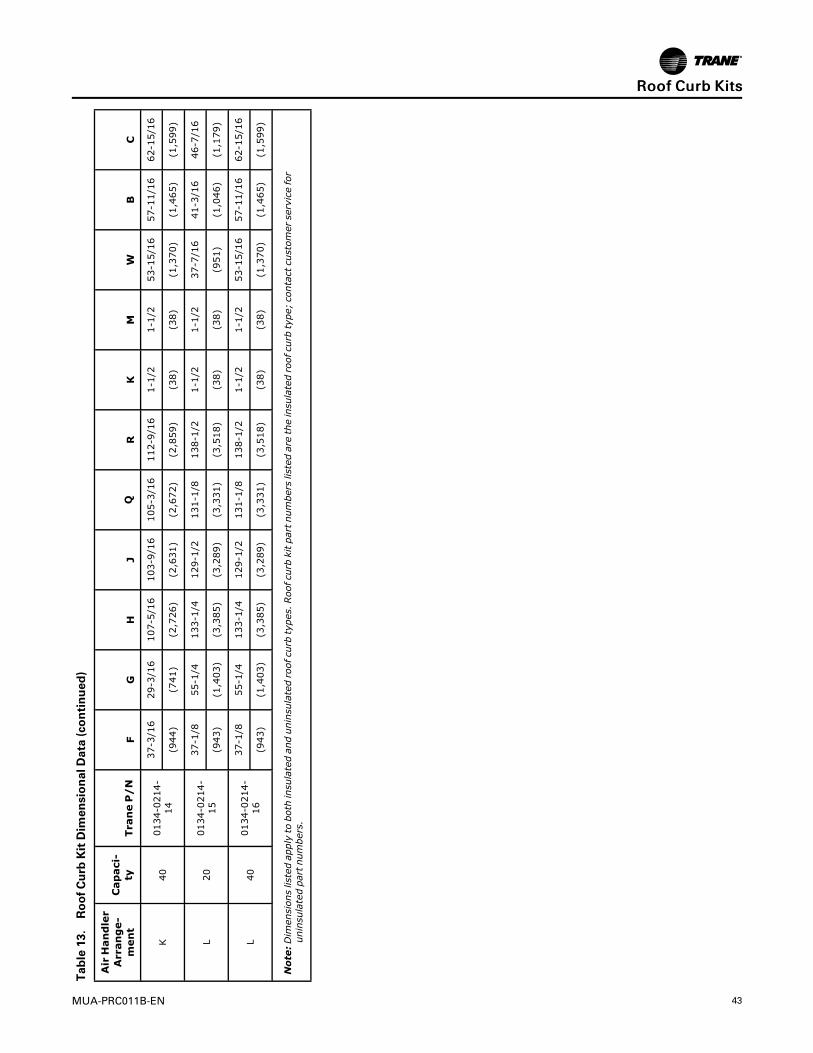
Table13.RoofCurbKitDimensionalData(continued)
AirHandler
Arrange-
ment
Capaci-
tyTraneP/N
FG
HJ
QR
KM
WB
C
K40
0134-0214-
14
37-3/16
29-3/16
107-5/16
103-9/16
105-3/16
112-9/16
1-1/2
1-1/2
53-15/16
57-11/16
62-15/16
(944)
(741)
(2,726)
(2,631)
(2,672)
(2,859)
(38)
(38)
(1,370)
(1,465)
(1,599)
L20
0134-0214-
15
37-1/8
55-1/4
133-1/4
129-1/2
131-1/8
138-1/2
1-1/2
1-1/2
37-7/16
41-3/16
46-7/16
(943)
(1,403)
(3,385)
(3,289)
(3,331)
(3,518)
(38)
(38)
(951)
(1,046)
(1,179)
L40
0134-0214-
16
37-1/8
55-1/4
133-1/4
129-1/2
131-1/8
138-1/2
1-1/2
1-1/2
53-15/16
57-11/16
62-15/16
(943)
(1,403)
(3,385)
(3,289)
(3,331)
(3,518)
(38)
(38)
(1,370)
(1,465)
(1,599)
Note:Dimensionslistedapplytobothinsulatedanduninsulatedroofcurbtypes.Roofcurbkitpartnumberslistedaretheinsulatedroofcurbtype;contactcustomerservicefor
uninsulatedpartnumbers.
RRooooff CCuurrbb KKiittss
44 MUA-PRC011B-EN
Figure 26. Roof Curb Kit Dimensions
RRooooff CCuurrbb KKiittss
MUA-PRC011B-EN 45
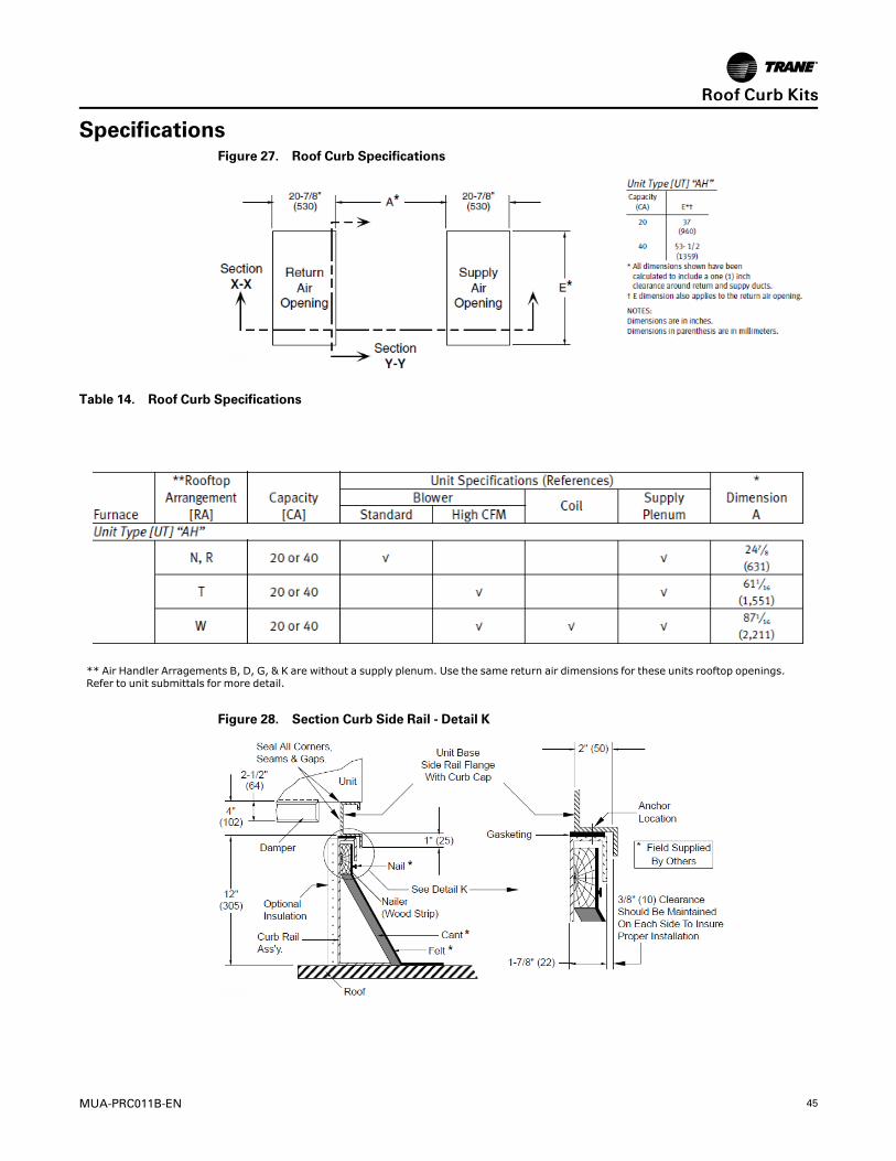
SpecificationsFigure 27. Roof Curb Specifications
Table 14. Roof Curb Specifications
** Air Handler Arragements B, D, G, & K are without a supply plenum. Use the same return air dimensions for these units rooftop openings.Refer to unit submittals for more detail.
Figure 28. Section Curb Side Rail - Detail K
RRooooff CCuurrbb KKiittss

46 MUA-PRC011B-EN
AssemblyFigure 29. Roof Curb Kit Assembly
NNoottee:: Refer to Roof Curb Specifications for “A” dimensions and references to sections X-X andY-Y.
Unit/Curb End Rail AssemblyFor Field Installations: These crossbrace/curb adapters (2 adapters ship with each rooftoparrangement) must be repositioned in the field when the unit is mounted on a curb or a platform(one for each end). Remove the screws, turn the piece over (end for end), and secure in placeusing the holes/hardware provided.
IImmppoorrttaanntt:: All joints and seams must be sealed completely in the field to prevent leaks
Figure 30. End Rail Assembly
RRooooff CCuurrbb KKiittss
MUA-PRC011B-EN 47
Engineered Products Specification Guide
A. General
A.1 Standards and Certifications
A.1.a ETL or UL Certified for electrical safety in compliance with UL 1995 safety standard for heating,ventilating and cooling equipment (see previous information).
A.2 Mechanical Arrangements
Rooftop unit will consist of a:
A.2.a Blower section containing supply blower(s) and blower motor. The blower motor will be inter-lockedelectrically and disengage the blower motor and control circuit upon opening the service panel.
A.2.b Electrical Cabinet that is isolated from the air stream with a non removable access panel interior to theouter service panel. Provision for component mounting, wire routing and high voltage isolation.
A.2.c Rooftop unit will be provided with:(a) Outside air and Return air opposed blade dampers.(b) Outside air opposed blade dampers.(c) Return air opposed blade dampers.(d) No dampers.
A.2.d Filter Section will accommodate 1 or 2" washable, pleated high-efficiency filters, or 2" throwaway; andbe of a V-bank design for minimal pressure drop.
A.2.e Supply plenum will be provided with down flow discharge.
A.2.f Return air will enter through a bottom return air opening.
A.2.f.1 (opt.) For units with both Outside and Return Air, Return air opening will be located horizontally on therear of the unit under the outside air inlet.
A.2.g A Cooling Coil Section constructed of galvanized steel will be provided with the unit.
A.2.g.1 Direct Expansion (DX) Evaporator Coil certified by ARI will be provided.
A.2.g.2 Chilled Water Coil certified by ARI will be provided.
A.2.h An Evaporative Cooler with 8" CELdek®media will be provided. The Evaporative cooler will be of a selfcleaning design with a stainless steel water tank, regulated water flow and overflow protection. Thecooler will have a cabinet assembly of heavy-gauge aluminized steel with weatherproof finish, a U.L.recognized thermally protected sealed re-circulating pump motor, two inch distribution pad, andcorrosion resistant PVC water distribution tubes.
A.2.h.1 (opt.) An automatic Fill and Drain Kit will be provided for field installation.
A.2.h.2 (opt.) A platform Mounting Curb will be provided.
A.2.h.3 (opt.) High-Efficiency 12" deep CELdek media will be provided.
A.2.h.4 (opt.) UL900 Class II fire rated 8" GLASdek®media will be provided.
A.2.h.5 (opt.) UL900 Class II fire rated 12" GLASdek media will be provided.
A.2.I (opt.) The unit will mount on a factory supplied roof curb, that is shipped un-assembled with hardwarepackage and gasket attached. Curb and rail will total 16 inches high and supplied with a cross-memberwhich allows isolation of return and supply air streams. Curb will be:(a) Insulated.(b) (opt.) Spring Isolated.(c) (opt.) Adapter Type.(d) Seismic Rated.
A.3 Electrical Systems
A.3.a All electrical components and fixtures will carry UL or ETL listing, certification and/or recognition.
A.3.b All wire will be rated to meet or exceed electrical requirements for voltage, ampacity, dielectric strengthof sheathing and temperature rating per location.
A.3.c Standard control relays will be socket mounted with terminal block connections.
48 MUA-PRC011B-EN
A.3.d All high voltage wiring will be enclosed in flexible metallic sheathed BX cable and include an identifyingmarker corresponding to the wiring diagram.
A.3.e All control wiring will terminate at terminal strips (single point connection) and include an identifyingmarker corresponding to the wiring diagram.
A.4 Mounting
Rooftop unit will be mounted on metal rails with down-rolled outer edges with lifting and anchor holesand be suitable for slab or curb mounting.
A.5 Standard Safety Provisions
A.5.a Rooftop unit will be provided with a low voltage circuit breaker rated for 150% of the units normal 24volt operating load.
A.5.b An access interlock switch will be installed in the blower compartment and will disengage the blowerupon opening the service panel. An override or cheat switch will be incorporated into the interlock switchfor serviceability.
A.5.c Warning labels will be visible in accessible areas of the rooftop where unsafe conditions could occur.
A.6 Optional Safety Provisions
A.6.a Rooftop unit will be provided with a Firestat located in the return air stream. If the return airtemperature reaches the set point (typically 130°F) the unit will close all gas valves, return dampers totheir normal position and shut down the blower.
A.6.b Rooftop unit will be provided with a Firestat located in the supply air stream. If the supply airtemperature reaches the set point (typically 150°F) the unit will close all gas valves, return dampers totheir normal position and shut down the blower.
A.6.c Rooftop unit will be provided with a Time Delay Freezestat with the sensing bulb located in the dischargeair stream. Wired as an interlock to prevent cold air discharge.
A.6.d A Clogged Filter Pressure Switch with adjustable operating range and normally open switch will beinstalled to sense increased suction pressure by the blower due to filter obstruction. Provision for remoteindication will be provided by terminal block connection points.
B. Cabinetry
B.1 Cabinetry will be die-formed, 18 gauge Galvanized steel and finished in air-dry enamel.
B.2 Hinged Access Doors will be provided by the manufacturer on the blower and filter cabinet doors. Doorswill be double wall construction and incorporate dual quick opening tool-less latches. Door stops will beincluded to prevent against closure while open.
B.3 Supply Plenums and coil section (when provided) will be insulated with fire resistant, environmentallysafe, odorless, one inch fiber material.
C. Dampers
Dampers will be of the opposed blade type, constructed of galvanized steel with neoprene nylonbushings, blades to be mechanically interlocked. (opt.) Low Leak Damper (outside air only) will be of theopposed blade type, constructed of galvanized steel with neoprene nylon bushings and vinyl blade edgeseals, blades to be mechanically interlocked.
D. Filter Rack
Filter Rack will be constructed of galvanized steel with access through the side service panel.
E. Intake Hood
Intake hood will be constructed of galvanized steel and include a:(std.) bird screen.(opt.) moisture eliminator.
F. Supply Blower
Supply Blower will be belt driven, forward curved, centrifugal type blower assembly, statically anddynamically balanced with double inlet. The blower wheel will be fixed on a shaft, supported with superquiet rubber cartridges for vibration isolation, and ball bearing.
G. Blower Motor
G.1 Type
EEnnggiinneeeerreedd PPrroodduuccttss SSppeecciiffiiccaattiioonn GGuuiiddee

MUA-PRC011B-EN 49
G.1.a Motor will be Single Speed, Ball Bearing Drive, Permanently Lubricated, EPACT Compliant, StandardNEMA Frame Size and Service Factor, with Resilient Base and Class B Windings:(a) Open Drip Proof(b) Totally Enclosed(c) Premium Efficiency, Open Drip Proof(d) Premium Efficiency, Totally Enclosed
G.1.b Motor will operate at:(a) 115V/1/60(b) 208V/1/60(c) 230V/1/60(d) 208V/3/60(e) 230V/3/60(f ) 460V/3/60(g) 575V/3/60
G.1.c Motor will have a horse power rating of: (1/2 - 15 HP)
G.2Wiring
Motor wiring will be enclosed in flexible metallic sheathed BX conduit.
G.3 Control
Motor will be activated through a:(a) Relay. (std. 1/2 - 1 HP)(b) Contactor. (std. 1-1/2 - 5 HP)(c) Magnetic starter. (std. 7-1/2 - 15 HP)(d) Variable frequency drive. (opt.)
G. 4 Motor Protection shall be provided with:
(a) Internal thermal protection. (Relay/Contactor actuated)(b) IEC overload protection. (Magnetic starter)
H. Damper Motor
H.1 Type
H.1.a Damper motor will be: (a) Two position with spring return. (b) Modulating. (c) Modulating with springreturn.
H.1.b Motor will operate at 24 volts.
H.2Wiring
Motor and control wiring will be harnessed with terminal block connections. Wire will have atemperature rating of at least 105°C.
I. Damper Control
(a) Two position spring return motor with outside air damper will be provided. The motor will power theoutside air damper full open when the unit is on and full closed when the unit is off.
(b) Two position spring return motor with return air damper will be provided. The motor will power thereturn air damper full open when the unit is on and full closed when the unit is off.
(c) Two position spring return motor with interlocked outside and return air dampers will be provided. Themotor will power either the outside air damper full open and the return air damper full closed or theoutside air damper full closed and the return air damper full open in response to an outside airtemperature sensor. When the unit is off the motor will drive the outside air dampers full closed and thereturn air dampers full open.
(d) Modulating motor with spring return and interlocked outside and return air dampers will be provided.The motor will modulate the position of the outside and return air dampers in response to a thermostaticcontroller located in the mixed air stream. Units will also be provided with a minimum positionpotentiometer for minimum outside air damper position. When the unit is off the motor will drive theoutside air dampers full closed and the return air dampers full open.
(f) Modulating motor with spring return and interlocked outside and return air dampers will be provided.The motor will modulate the position of the outside and return air dampers in response to a thermostaticcontroller located in the mixed air stream. When the unit is off the motor will drive the outside airdampers full closed and the return air dampers full open.
EEnnggiinneeeerreedd PPrroodduuccttss SSppeecciiffiiccaattiioonn GGuuiiddee

50 MUA-PRC011B-EN
(h) Modulating motor with spring return and interlocked outside and return air dampers will be provided.The motor will position the outside and return air dampers in response to a manually set potentiometer.When the unit is off the motor will drive the outside air dampers full closed and the return air dampersfull open.
(j) Modulating motor with spring return and interlocked outside and return air dampers will be provided.The motor will modulate the position of the outside and return air dampers in response to a thermostaticcontroller and dry bulb located in the mixed air stream. Units will also be provided with a minimumposition potentiometer for minimum outside air damper position. When the unit is off the motor willdrive the outside air dampers full closed and the return air dampers full open.
(k) Modulating motor with spring return and interlocked outside and return air dampers will be provided.The motor will modulate the position of the outside and return air dampers in response to an enthalpycontrolled economizer. When the unit is off the motor will drive the outside air dampers full closed andthe return air dampers full open.
(l) Modulating motor with interlocked outside and return air dampers will be provided. The motor willmodulate the position of the outside and return air dampers in response to a pressure sensor located inthe building. When the unit is off the motor will drive the outside air dampers full closed and the returnair dampers full open.
(m) Modulating motor with interlocked outside and return air dampers will be provided. The motor willmodulate the position of the outside and return air dampers in response to a carbon monoxide monitorlocated in the return air duct. When the unit is off the motor will drive the outside air dampers full closedand the return air dampers full open.
(n) Modulating motor with spring return and inter-locked outside and return air dampers will be provided.The motor will modulate the position of the outside and return air dampers in response to a solid statemixed air sensor and S-350 proportional controller. When the unit is off the motor will drive the outsideair dampers full closed and the return air dampers full open.
(o) Modulating motor with interlocked outside and return air dampers will be provided. The motor willmodulate the position of the outside and return air dampers in response to a 4-20 mA or 0-10 VDCanalog signal supplied by an external DDC controller.
(p) Modulating motor with spring return and interlocked outside and return air dampers will be provided.The motor will modulate the position of the outside and return air dampers in response to a 4-20 mA or0-10 VDC analog signal supplied by an external DDC controller. When the unit is off the motor will drivethe outside air dampers full closed and the return air dampers full open.
(q) Two position spring return motor with interlocked outside and return air dampers will be provided. Themotor will power the outside air damper full open after a warm up period determined by a minimumsupply air temperature sensor when the unit is on, and full closed when the unit is off (ASHRAE Cycle I).
(r) Modulating motor with spring return and interlocked outside and return air dampers will be provided.The motor will modulate the position of the outside and return air dampers in response to a thermostaticcontroller located in the mixed air stream after a warm up period determined by a minimum supply airtemperature sensor. Units will also be provided with a minimum position potentiometer for minimumoutside air damper position (ASHRAE Cycle II).
(s) Modulating motor with spring return and interlocked outside and return air dampers will be provided.The motor will modulate the position of the outside and return air dampers in response to a thermostaticcontroller located in the mixed air stream after a warm up period determined by a minimum supply airtemperature sensor. Units will also be provided with a minimum position potentiometer for minimumoutside air damper position. When the unit is off the motor will drive the outside air dampers full closedand the return air dampers full open (ASHRAE Cycle III).
(t) Manual outside and return air dampers with manual quadrant will be provided.
J. Accessories
(a) Moisture EliminatorsMoisture eliminators will be provided by the manufacturer to eliminate the possibility of moisturecarryover entering the unit through the outside air hood. A differential pressure switch and indicatorlight will be provided in case of blockage.
(b) Horizontal Rear ReturnReturn air will be located horizontally on the rear of the unit under the outside air inlet. Moistureeliminators will be provided by the manufacturer for the outside air hood.
(c) Low Leak DampersLow leak dampers with vinyl blade edge seams and neoprene nylon bushings will be provided by themanufacturer. Dampers will be of the galvanized steel opposed blade type.
(d) Filters will consist of:
EEnnggiinneeeerreedd PPrroodduuccttss SSppeecciiffiiccaattiioonn GGuuiiddee

MUA-PRC011B-EN 51
d.1 1"Washable (Standard)
d.2 2"Washable (Optional)
d.3 2"Throwaway (Optional)
d.4 1"30% Pleated (Optional)
d.5 2"30% Pleated (Optional)
(e) Evaporative Cooler Accessories include:
e.1 Fill and Drain KitWill consist of a 3 way valve and relay for automatic fill and drain operation of the Evaporative Cooler.
e.2 12" Celdek® Media High Efficiency12" Celdek Media will be utilized in the Evaporative cooler.
e.3 FreezestatAn automatic reset freezestat will be provided by the manufacturer to control the operation of the fill anddrain kit.
e.4 8" Glasdek®Will be provided by the manufacture to conform with UL900 Class II fire rating requirements
e.5 12" Glasdek®Will be provided by the manufacture to conform with UL900 Class II fire rating requirements
(f) 7 Day Time ClockA 7 day time clock will be provided by the manufacturer and offer SPDTrelay output and a maximum of 6set points per day.
(g) 24 Hour Time ClockA 24 hour time clock will be provided by the manufacturer and offer SPDTrelay output and a maximumof 12 set points per day.
(h) Clogged Filter SwitchA factory installed clogged filter switch with indicator light located in the main electrical cabinet orremote control panel (when specified) will be provided by the manufacturer.
(i) Convenience OutletA GFI with manual reset convenience outlet in a weather proof enclosure will be provided by themanufacturer for field installation requiring separate 115 volt service.
(j) Remote Control PanelA wall mounted Trane design control panel will be provided by the manufacturer. The panel will consist ofa non metallic enclosure and 6 LED status lamps. The lamps will indicate System on/off, Fan on/off, Heaton/off, Cool on/off, Auxiliary on/off (Evaporative cooler on/off or Exhaust fan operation) and modulatingdamper control (when specified)
(k) Manual Blower Switch A factory installed manual blower switch located in the electrical cabinet will beprovided by the manufacturer.
(l) Duct Thermostats
l.1 Single stage duct thermostat with an operating range of 55-175°F and SPDToperation will be providedby the manufacturer.
l.2 Two stage duct thermostat with an operating range of 55-175°F and SPDToperation will be provided bythe manufacturer.
(m) Room Thermostats (All Mercury Free)
m.1 T87K Honeywell Thermostat w/SubbaseA single stage heating and subbase for fan on operation will be provided by the manufacturer.
m.2 T87K Honeywell Thermostat w/Subbase and GuardA single stage heating thermostat including a subbase for fan operation and tamper proof guard will beprovided by the manufacturer.
m.3 T834N Thermostat with SubbaseA single stage heating thermostat with fan switch with a 50-90°F operating range will be provided by themanufacturer.
m.4 TB8220U Programmable Commercial ThermostatThe manufacturer will provide a 7 day programmable thermostat capable of two stages of heating andtwo stages of cooling.
EEnnggiinneeeerreedd PPrroodduuccttss SSppeecciiffiiccaattiioonn GGuuiiddee

52 MUA-PRC011B-EN
m.5 TH5220D Two Stage ThermostatThe manufacturer will provide a two stage heating and two stage cooling thermostat with system andfan switching and built in 10°F heating /cooling differential.
m.6 TG511 Locking Thermostat CoverA Universal locking thermostat cover will be provided by the manufacturer.
(n) Return FirestatA return firestat with a set point range of 130° - 270°F and SPDTswitching capabilities will be providedby the manufacturer.
(o) Supply FirestatA supply firestat with a setpoint range of 130° - 270°F and SPDTswitching capabilities will be providedby the manufacturer.
(p) Time Delay FreezestatA SPDT time delay freeze-stat with a set point range of 30° - 58°F and a 1 to 5 minute adjustable timedelay will be provided by the manufacturer.
(q) Ambient LockoutA factory mounted ambient lockout control for application specific control based on intake airtemperature will be provided by the manufacturer.
(r) Interlock Relays
r.1 24 Volt DPDT RelayA 24 volt type 2 Form C relay with 24 volt coil and DPDT 10 amp contacts will be provided by themanufacturer. The relay will be capable of plugging into the main connection PC board and will beutilized as an exhaust fan interlock.
r.2 24/115 Volt SPDT RelayA relay with selectable coils voltages of 24 or 115 and SPDT 10 amp contacts will be provided by themanufacturer.
r.3 24/115/230Volt DPDT RelayA relay with selectable coils voltages of 24, 115 or 230 and DPDT 10 amp contacts will be provided bythe manufacturer.
r.4 24 Volt 4PDT RelayA relay with a coil voltage of 24 and 4PDT 10 amp contacts will be provided by the manufacturer.
(s) Status LampsLong life factory installed LED lamps will be provided in the electrical cabinet by the manufacturer to aidin troubleshooting and equipment setup. Power on, Fan on, Heating energized at furnace one, two orthree and cooling energized will be provided when applicable.
(t) Air Flow Prove SwitchWill be provided by the manufacturer to verify airflow through the unit. The switch will be a Dwyer 1910-0 pressure switch suitable for duct mounting with a range of .15 – .50" W.C.
(u) Field Installed Disconnect Switches
u.1 30amp Fused Disconnect Switch will be provided by the manufacturer to be field mounted.
u.2 30amp Non Fused Disconnect Switch will be provided by the manufacturer to be field mounted.
u.3 60amp Fused Disconnect Switch will be provided by the manufacturer to be field mounted.
u.4 60amp Non Fused Disconnect Switch will be provided by the manufacturer to be field mounted.
(v) Variable Frequency Drive Options
v.1 Field Installed VFDWill be provided by manufacturer to provide overload protection and soft start operation. VFD to be ULapproved manufactured with a NEMA 1 plenum rated enclosure.
v.2 Factory Installed VFDWill be provided by manufacturer to provide overload protection and soft start operation manufacturedwith a NEMA 1 plenum rated enclosure. VFD to be factory mounted in the unit blower cabinet and factorywired with a remote programming keypad located in the electrical cabinet.
v.3 Remote KeypadWill be provided by manufacturer for field installation up to 100 ft. (30 Meters) from the drive. Theremote keypad will duplicate the functionality of the drive’s local keypad.
EEnnggiinneeeerreedd PPrroodduuccttss SSppeecciiffiiccaattiioonn GGuuiiddee
MUA-PRC011B-EN 53
v.4 CO2 Sensor 100% Outside AirWill be provided by manufacturer for field installation. CO2 monitor range 0 to 2,000 ppm, adjustable,for mounting in occupied space. Upon rise in CO2 above field programmed set point, 0-10VDC or 4-20mA signal will be sent from CO2 sensor to VFD to modulate air flow between minimum set point andmaximum CFM.
v.5 CO2 Mixed AirWill be provided by manufacturer for field installation. CO2 monitor range 0 to 2,000 ppm, adjustable,for mounting in return air duct. Upon rise in CO2 above field programmed set point, signal will drivereturn air damper to 100% closed and outside air damper to 100% open. 0-10VDC or 4-20 mA signalwill be sent from CO2 sensor to VFD to modulate air flow between minimum set point and maximumCFM.
v.6 Pressure SensorWill be provided by manufacturer for field installation. Pressure control range - 0.1 to +0.1" W.C. VFDwill modulate motor speed based on 4-20 mA signal from pressure control sensor mounted in space tomaintain field programmed set point.
v.7 2-Speed VFD RelaysFactory installed DPDTrelays provided to energize second speed setting. Relay coil will accept 24V,115V and 230V.
v.8 3-Speed VFD RelaysFactory installed DPDTrelays provided to energize second and third speed settings. Relay coil will accept24V, 115V and 230V.
v.9 VFD EnclosureA factory installed NEMA-3R enclosure will be provided to protect the factory installed VFD in outdoorapplications. Enclosure will include a small electric heater and vent fan to protect the VFD in ambienttemperatures of -30 - 115°F (-34 - 46°C).
(w) Through –The – Base Utility PenetrationsWill be provided by the manufacturer. Electric and coil connections will enter the unit in the blowercabinet.
(x) Service Convenience PackageWill be factory installed by the manufacturer. The service convenience package will consist of a factorymounted switch type disconnect and GFI convenience outlet mounted on the hinged access door. Utilityconnections will be through–the–base. Through–the–base utility penetrations for the electric and coilconnections will enter the unit in the blower cabinet.
(y) Double Wall Cabinet ConstructionWill be factory installed and in accordance with the ASHRAE standard no. 62-1989. Double wallconstruction will be utilized in the Blower, Filtration, Coil and Down Discharge Plenum sections of the unitwere applicable. 1" fiber material will be used between the cabinet walls for insulation purposes.
EEnnggiinneeeerreedd PPrroodduuccttss SSppeecciiffiiccaattiioonn GGuuiiddee

54 MUA-PRC011B-EN
Approximate Unit Net and Ship WeightsAir Handler Arrangements
Table 15. Air Handler Arrangements
Note: All unit weights are expressed in lbs. and are less motor, outside air hood, and cooling coils with drain pan.
Table 16. Outside Air Hood with Bird Screen Weight Adder
Capacity(CA)
Weight
20 51
40 63
Cooling Coil Weight AdderRefer to the Coil Weights Options tables.
Double Wall Construction AdderFor units with double wall construction, add an additional 10% of the base unit weight.
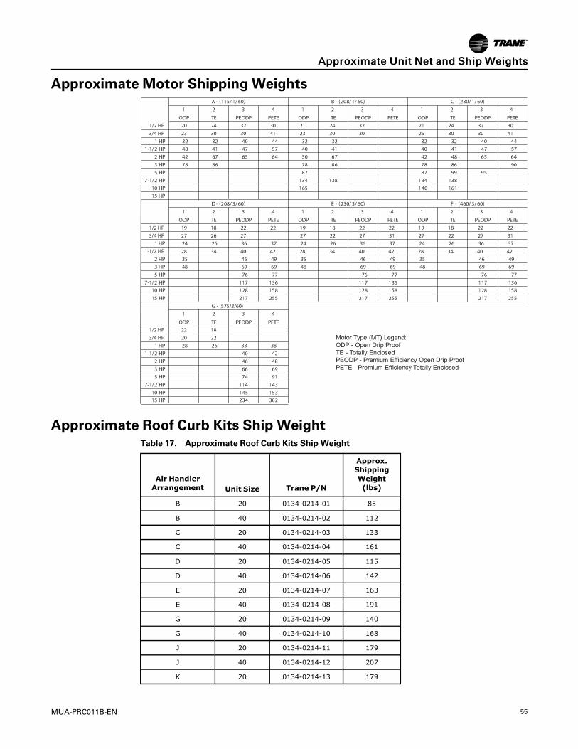
MUA-PRC011B-EN 55
Approximate Motor Shipping Weights
Approximate Roof Curb Kits Ship WeightTable 17. Approximate Roof Curb Kits Ship Weight
Air HandlerArrangement Unit Size Trane P/N
Approx.ShippingWeight(lbs)
B 20 0134-0214-01 85
B 40 0134-0214-02 112
C 20 0134-0214-03 133
C 40 0134-0214-04 161
D 20 0134-0214-05 115
D 40 0134-0214-06 142
E 20 0134-0214-07 163
E 40 0134-0214-08 191
G 20 0134-0214-09 140
G 40 0134-0214-10 168
J 20 0134-0214-11 179
J 40 0134-0214-12 207
K 20 0134-0214-13 179
AApppprrooxxiimmaattee UUnniitt NNeett aanndd SShhiipp WWeeiigghhttss
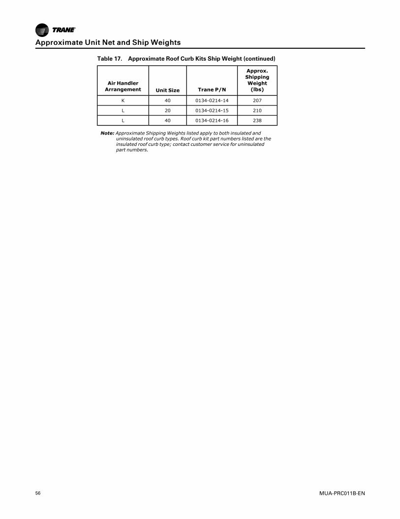
56 MUA-PRC011B-EN
Table 17. Approximate Roof Curb Kits Ship Weight (continued)
Air HandlerArrangement Unit Size Trane P/N
Approx.ShippingWeight(lbs)
K 40 0134-0214-14 207
L 20 0134-0214-15 210
L 40 0134-0214-16 238
Note: Approximate Shipping Weights listed apply to both insulated anduninsulated roof curb types. Roof curb kit part numbers listed are theinsulated roof curb type; contact customer service for uninsulatedpart numbers.
AApppprrooxxiimmaattee UUnniitt NNeett aanndd SShhiipp WWeeiigghhttss

MUA-PRC011B-EN 57
Motor Electrical Data

58 MUA-PRC011B-EN
NNootteess

MUA-PRC011B-EN 59
NNootteess

Ingersoll Rand (NYSE: IR) advances the quality of life by creating comfortable, sustainable and efficientenvironments. Our people and our family of brands— including Club Car®, Ingersoll Rand®, Thermo King® andTrane®—work together to enhance the quality and comfort of air in homes and buildings; transport and protectfood and perishables; and increase industrial productivity and efficiency. We are a global business committed to aworld of sustainable progress and enduring results.
ingersollrand.com
Ingersoll Rand has a policy of continuous product and product data improvements and reserves the right to change design and specificationswithout notice.We are committed to using environmentally conscious print practices.
MUA-PRC011B-EN 31 May 2017
Supersedes MUA-PRC011A-EN (March 2017) ©2017 Ingersoll Rand