warning: do not operate before reading · pdf fileblower systems are built to exacting...
TRANSCRIPT

M-D Pneumatics™
Rotary Positive DisplacementAir Blower System
Qube™
Models 4008001600
OPERATOR’S MANUAL
Manual 2011 Rev A p/n 2011
Tuthill Vacuum & Blower Systems tuthillvacuumblower.com 800.825.6937
WARNING: Do Not Operate Before Reading Manual
Oper
ator
’s M
anua
l: Tu
thill
Qub
e Ro
tary
Pos
itive
Disp
lace
men
t Air
Blow
er Sy
stem
2
TABLE OF CONTENTS
SECTION PAGE
1. INTRODUCTION 3
1.1 APPLICABLE DOCUMENTATION 3
1.2 SCOPE OF MANUAL 3
2. CONVENTIONS AND DATA PLATE 3
2.1 GRAPHIC CONVENTIONS IN THIS MANUAL 3
2.2 DATA PLATE 4
3. DESCRIPTION 5
4. INSTALLATION 6
4.1 UNPACKING AND HANDLING 7
4.2 STORAGE 7
4.3 LOCATION 7
4.3.1 LEVELING 8
4.3.2 FOUNDATION 8
4.4 SAFETY 8
4.5 COOLING AIR INTAKE AND DISCHARGE 8
4.6 MOTOR AND ELECTRICAL CONNECTIONS 9
4.7 PIPING 10
4.8 LUBRICATION 12
4.8.1 OIL FILL INSTRUCTIONS 12
4.8.2 FREQUENTLY ASKED QUESTIONS REGARDING LUBRICATION 13
5. OPERATION 14
5.1 START-UP CHECKLIST 15
5.2 STOPPING 15
5.3 PRESSURE RELIEF VALVE 15
5.4 ACCESSORIES 16
5.4.1 NOISE CONTROL ENCLOSURE 16
5.4.2 INTEGRAL SILENCER/BASE 16
5.4.3 COOLING FAN 16
5.4.4 AIR FILTER RESTRICTION GAUGE 17
5.4.5 DISCHARGE PRESSURE GAUGE 17
5.4.6 CHECK VALVE 17
6. MAINTENANCE 18
6.1 OIL INDICATOR, FILL AND DRAIN 18
6.2 AIR FILTER 18
6.3 V-BELTS 19
6.4 PREVENTATIVE MAINTENANCE 20
6.5 LONG TERM STORAGE 20
7. TROUBLESHOOTING 21
8. RECOMMENDED LUBRICANTS 22
9. PARTS LISTS AND DRAWINGS 24
10. DECLARATION OF CONFORMITY 33
11. WARRANTY — BLOWER PRODUCTS 34
12. OPERATING DATA FORM / PRODUCT REGISTRATION 35
3
1. INTRODUCTION
CONGRATULATIONS on your purchase of a new Tuthill Qube™ Rotary Positive Displacement Air Blower Package from Tuthill Vacuum & Blower Systems. Please examine for shipping damage, and if any damage is found, report it immediately to the carrier. If the blower is to be installed at a later date make sure it is stored in a clean, dry location and the blower rotated regularly. Make sure covers are kept on all openings. If blower is stored outdoors be sure to protect it from weather and corrosion.
Qube blower systems are built to exacting standards, and if properly installed and maintained will provide many years of reliable service. We urge you to take time to read and follow every step of these instructions when installing and maintaining your system. We have tried to make these instructions as straightforward as possible, as we realize getting any new piece of equipment up and running in as little time as possible is imperative to production.
Additional manuals may ship with your Qube that provide detailed operation and maintenance instructions for the Tuthill blower and the electric motor included with your Qube. We urge you to read and understand all operation and maintenance instructions prior to startup.
NOTERecord the blower model and serial numbers of your machine in the OPERATING DATA form on the inside back cover of this manual. You will save time and expense by including this reference identification on any replacement part orders, or if you require service or application assistance.
1.1 APPLICABLE DOCUMENTATION
The applicable documents associated with this manual are:• 2006/42/CE - Machinery Directive• EN 1012-1:1996 - Compressors and vacuum pumps - Safety Requirements - Part 1: Compressors
1.2 SCOPE OF MANUAL
The scope of this manual and the Declaration of Conformity, if supplied, includes the bare shaft rotary positive displacement blower.
2. CONVENTIONS AND DATA PLATE
2.1 GRAPHIC CONVENTIONS IN THIS MANUAL
This manual is the result of a risk assessment according the applicable documents referenced in section 1.1. The following are hazard levels are referenced within this manual:
DANGERIndicates an immediate hazardous situation which, if not avoided, will result in death or serious injury.
WARNINGIndicates that a physical injury or damage to health or property, if not avoided, could occur.

4
CAUTIONIndicates that a potential hazard may occur which, if not avoided, could result in minor or moderate injury.
NOTEIndicates a statement of information which, if not avoided, could cause damage to the product.
CAUTIONRead manual before operation or bodily harm may result. Attention should be given to the safety related sections of this manual.
2.2 DATA PLATE
General Operation and Symbols on Data Plate:
MODEL NUMBER: This identifies the specific model and designation of the package.
SERIAL NUMBER: Each package has a unique serial number. This number is to be used with any service issues and with any contact with the manufacturer.
MAWP: This states the maximum allowable working pressure (MAWP) of the package.
BLOWER SHAFT SPEED: This is the shaft speed of the blower (airend).
YEAR BUILT: This states the year that the package was manufactured.
MOTOR SIZE: This is the size of the motor in horsepower (HP) and kilowatt (kW).

5
This label is placed on the front of the machine. The covers (doors) shall not be opened while the machine is in operation. Proper lock-out, tag-out procedures should be followed.
This label is placed at the process outlet. The outlet can approach temperatures as high as 400° F (204° C).
This label is placed at the process outlet. High pressure and flow exist at the process outlet with exposure to pressure relief valve.
3. DESCRIPTION
TABLE 1 — SPECIFICATIONS
MODEL MAX. RPMMAWP
psi / bar
APPROXIMATE WEIGHTLBS. / KG
WITHOUT MOTOR WITH MOTOR
400 4800 18 / 1241 824 / 374 1599 / 726
800 4000 18 / 1241 2550 / 1157 3550 / 1611
1600 3200 18 / 1241 3202 / 1453 5202 / 2360
For additional bare shaft blower information, refer to the appropriate bare shaft blower manual.
NOTE
Maximum ambient temperature is 104° F (40° C)

6
To permit continued satisfactory performance, a blower must be operated within certain approved limiting conditions. The manufacturer’s warranty is, of course, also contingent on such operation. Maximum limits for pressure, temperature and speed are specified here for various blower sizes when operated under the standard atmospheric conditions. Do not exceed any one of these limits.
NOTESpecial attention must be paid when a blower has a higher than standard ambient suction temperature. Special recommendations for operating parameters and/or additional cooling may be recommended. Consult the factory or local representative for appropriate information.
4. INSTALLATION
DANGERThe blower is not intended to be used with explosive products or in explosive environments.The blower is not intended to be used in applications that include hazardous gases.
The blower is not intended to be used in applications that include hazardous gases.
DANGERIt is the responsibility of the installer to assure that proper guarding is in place and compliant with all applicable regulatory requirements.
WARNINGCustomers are warned to provide adequate protection, warning and safety equipment necessary to protect personnel against hazards in the installation and operation of this equipment in the system or facility.
WARNINGThe Specifications Table (Table 1) states the maximum operating speed in RPM (rotations per minute), the maximum pressure. Do not exceed these limits. The installation of the blower shall take these critical operating parameters into account and adequate control features implemented.
WARNINGPipe loading on the blower should be negligible as pipe loading can cause distortion of the blower. Use proper supports and pipe hangers to assure that there is no loading.
CAUTIONUpon completion of the installation, and before operation, assure the proper rotation of the blower and that the blower rotates freely. If the blower does not rotate freely, look for uneven mounting, piping strain, excessive belt tension or any other cause of binding. If blower is removed and still does not move freely, check inside the blower housing for foreign material.
CAUTION
Must check to see if the cooling fan rotates freely and has no contact with the shroud. If there is contact, fan adjustment must be made.
7
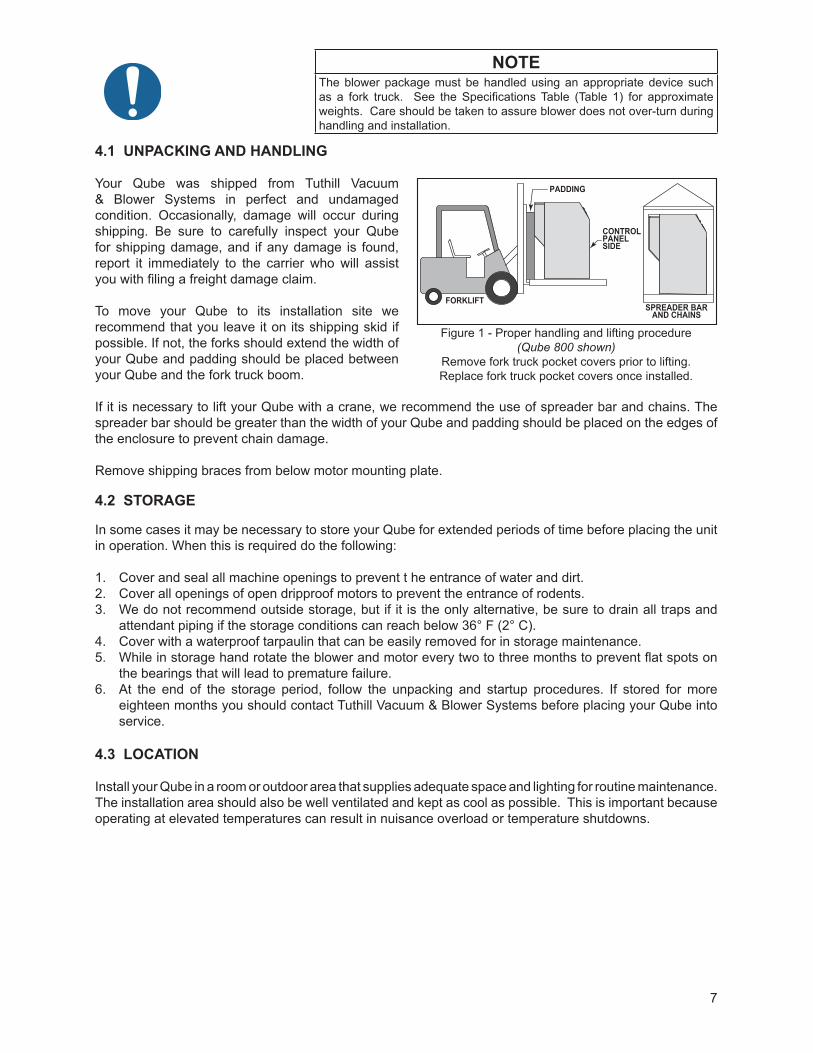
NOTEThe blower package must be handled using an appropriate device such as a fork truck. See the Specifications Table (Table 1) for approximate weights. Care should be taken to assure blower does not over-turn during handling and installation.
4.1 UNPACKING AND HANDLING
Your Qube was shipped from Tuthill Vacuum & Blower Systems in perfect and undamaged condition. Occasionally, damage will occur during shipping. Be sure to carefully inspect your Qube for shipping damage, and if any damage is found, report it immediately to the carrier who will assist you with filing a freight damage claim.
To move your Qube to its installation site we recommend that you leave it on its shipping skid if possible. If not, the forks should extend the width of your Qube and padding should be placed between your Qube and the fork truck boom.
If it is necessary to lift your Qube with a crane, we recommend the use of spreader bar and chains. The spreader bar should be greater than the width of your Qube and padding should be placed on the edges of the enclosure to prevent chain damage.
Remove shipping braces from below motor mounting plate.
4.2 STORAGE
In some cases it may be necessary to store your Qube for extended periods of time before placing the unit in operation. When this is required do the following:
1. Cover and seal all machine openings to prevent t he entrance of water and dirt. 2. Cover all openings of open dripproof motors to prevent the entrance of rodents. 3. We do not recommend outside storage, but if it is the only alternative, be sure to drain all traps and
attendant piping if the storage conditions can reach below 36° F (2° C).4. Cover with a waterproof tarpaulin that can be easily removed for in storage maintenance. 5. While in storage hand rotate the blower and motor every two to three months to prevent flat spots on
the bearings that will lead to premature failure. 6. At the end of the storage period, follow the unpacking and startup procedures. If stored for more
eighteen months you should contact Tuthill Vacuum & Blower Systems before placing your Qube into service.
4.3 LOCATION
Install your Qube in a room or outdoor area that supplies adequate space and lighting for routine maintenance. The installation area should also be well ventilated and kept as cool as possible. This is important because operating at elevated temperatures can result in nuisance overload or temperature shutdowns.
Figure 1 - Proper handling and lifting procedure (Qube 800 shown)
Remove fork truck pocket covers prior to lifting.Replace fork truck pocket covers once installed.
FORKLIFT
CONTROL PANELSIDE
PADDING
SPREADER BARAND CHAINS
8
4.3.1 LEVELING
The Qube blower system should be placed on a level, even, flat, vibration-less surface to avoid equipment damage. The Qube blower system shall be level to 1/8” per 10 feet (this equates to a leveling tool with an accuracy of at least 0.001”/in., readily available levels have accuracy of 0.0005”/in.). Level the unit and adjust with shims as required.
NOTEAn un-level unit can result in improper oil level and catastrophic failure of the unit.
4.3.2 FOUNDATION
Your Qube blower system does not need a special foundation, however it does require a solid, level floor and adequate frame support. Bolt the blower system to the floor and seal any cracks around the perimeter.
4.4 SAFETY
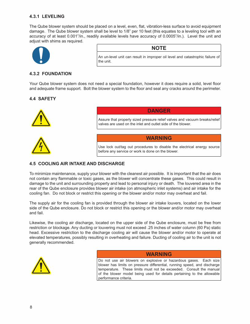
DANGERAssure that properly sized pressure relief valves and vacuum breaks/relief valves are used on the inlet and outlet side of the blower.
WARNINGUse lock out/tag out procedures to disable the electrical energy source before any service or work is done on the blower.
4.5 COOLING AIR INTAKE AND DISCHARGE
To minimize maintenance, supply your blower with the cleanest air possible. It is important that the air does not contain any flammable or toxic gases, as the blower will concentrate these gases. This could result in damage to the unit and surrounding property and lead to personal injury or death. The louvered area in the rear of the Qube enclosure provides blower air intake (on atmospheric inlet systems) and air intake for the cooling fan. Do not block or restrict this opening or the blower and/or motor may overheat and fail.
The supply air for the cooling fan is provided through the blower air intake louvers, located on the lower side of the Qube enclosure. Do not block or restrict this opening or the blower and/or motor may overheat and fail.
Likewise, the cooling air discharge, located on the upper side of the Qube enclosure, must be free from restriction or blockage. Any ducting or louvering must not exceed .25 inches of water column (60 Pa) static head. Excessive restriction to the discharge cooling air will cause the blower and/or motor to operate at elevated temperatures, possibly resulting in overheating and failure. Ducting of cooling air to the unit is not generally recommended.
WARNINGDo not use air blowers on explosive or hazardous gases. Each size blower has limits on pressure differential, running speed, and discharge temperature. These limits must not be exceeded. Consult the manual of the blower model being used for details pertaining to the allowable performance criteria.
9
If it is necessary to take air from a remote source, such as in a vacuum application, a vacuum kit will be necessary. The piping should be at least the same diameter of the blower inlet. For distances greater than 20 feet (6 m) the pipe diameter should be enlarged to reduce inlet restriction. Excessive restriction will reduce the efficiency of the blower and elevate its discharge temperature. The piping used should also be corrosion resistant, and free of scale and dirt. The inlet should be covered to keep out precipitation, insects, and small animals. Vacuum kits are available.
4.6 MOTOR AND ELECTRICAL CONNECTIONS
All electrical wiring should be performed by a qualified and licensed electrician in compliance with NEC and IEC standards and local codes as applicable. Be sure to investigate the local requirements before installing your Qube. For the Drive Motor, refer to the data plate on the drive motor for wiring details. The power supply should be adequate and free of parasitic loads that will cause an undervoltage condition during the operation of the blower. Otherwise, nuisance electrical shutdowns will result.
WARNINGThe motor and connections shall be protected to assure that product and environmental condensation does not come in contact with the electrical connections.
NOTEIt is the responsibility of the installer to assure that the motor is in compliance with the latest edition of IEC 60204-1 and all electrical connections performed per IEC 60204-1, this includes over current protection.
10
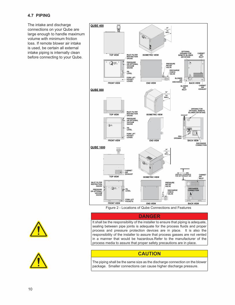
4.7 PIPING
The intake and discharge connections on your Qube are large enough to handle maximum volume with minimum friction loss. If remote blower air intake is used, be certain all external intake piping is internally clean before connecting to your Qube.
DANGERIt shall be the responsibility of the installer to ensure that piping is adequate, sealing between pipe joints is adequate for the process fluids and proper process and pressure protection devices are in place. It is also the responsibility of the installer to assure that process gasses are not vented in a manner that would be hazardous.Refer to the manufacturer of the process media to assure that proper safety precautions are in place.
CAUTIONThe piping shall be the same size as the discharge connection on the blower package. Smaller connections can cause higher discharge pressure.
FRONT VIEW
FRONT VIEW
QUBE 1600
QUBE 800
QUBE 400
FRONT VIEW END VIEW BACK VIEW
TOP VIEW
TOP VIEW
TOP VIEW ISOMETRIC VIEW
ISOMETRIC VIEW
ISOMETRIC VIEW
END VIEW BACK VIEW
END VIEW BACK VIEW
PRESSUREOR OPTIONALVACUUM GAUGE
OILLEVEL
OILLEVEL
DISCHARGE CONNECTION
OPENING FOROPTIONAL REMOTE
BLOWER AIR INTAKE
PRVOPENING
INLET
EXHAUST
INLET FILTERRESTRICTIONGAUGE
PRESSUREOR OPTIONAL
VACUUM GAUGE
INLET FILTERRESTRICTION
GAUGE
FORK LIFTPOCKETCOVER
FORK LIFTPOCKETS
PRESSUREOR OPTIONALVACUUM GAUGE
OILLEVEL
INLET FILTERRESTRICTIONGAUGE
PRESSURERELIEFVALVE
DISCHARGECHECKVALVE
PRESSURERELIEFVALVE
DISCHARGECHECKVALVE
DISCHARGECONNECTION
BLOWERAIR
INLET
CABINETAIR
EXHAUST12”
(304 mm)TO
WALL
24”(609 mm)
TOWALL
24”(609 mm)
TOWALL
36” (914 mm) MIN.VERTICAL CLEARANCEFOR HOT EXHAUST AIR
CABINETAIR
INLET
CABINETAIREXHAUST CABINET
AIRINLET
BLOWERAIR
DISCHARGE
FORK LIFTPOCKETCOVER
OPTIONALOPENING FOR
REMOTE BLOWERAIR INTAKE
Figure 2 - Locations of Qube Connections and Features
11
NOTEDamage to the blower could occur if there is blockage in the inlet or outlet ports or piping. Care should be taken when install the blower to assure that there are no foreign objects or restrictions in the ports or piping.
NOTE
Vacuum discharge must be piped away for sound/temperature requirements.
Tuthill recommends placing a 16-mesh wire screen backed with hardware cloth at the remote inlet connection of your Qube for the first 50 hours of use, until the system is clean. Clean the screen after a few hours of operation and discard of it once the system is clean. It is important to dispose of the screen at this time, as it will eventually deteriorate and small pieces going into the blower can cause serious damage.
A flex connector at the intake (if piped away) and discharge connections shall always be used.
NOTEFailure to use flex connectors at the intake and discharge connectors will cause stress at these location and could cause connection and equipment failures.
External piping at the intake and discharge connections shall be fully supported.
NOTEFailure to properly support the pipe at the intake and discharge connections will result in stress in these locations and could result in the unit being un-level.
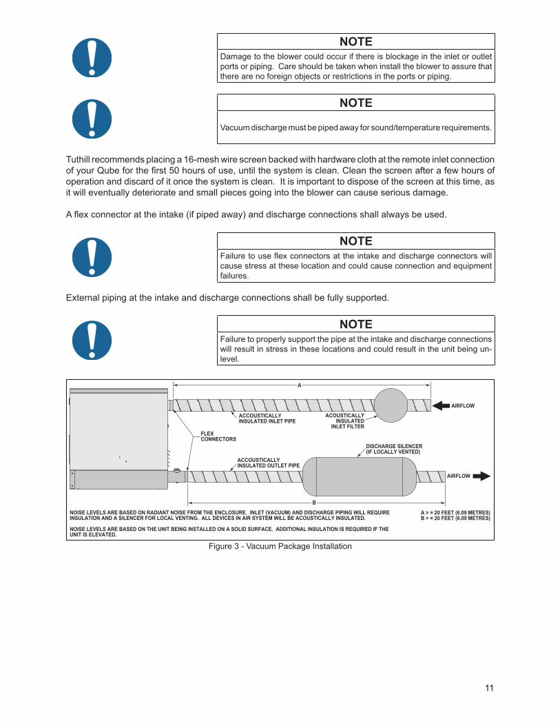
Figure 3 - Vacuum Package Installation
NOISE LEVELS ARE BASED ON RADIANT NOISE FROM THE ENCLOSURE. INLET (VACUUM) AND DISCHARGE PIPING WILL REQUIRE INSULATION AND A SILENCER FOR LOCAL VENTING. ALL DEVICES IN AIR SYSTEM WILL BE ACOUSTICALLY INSULATED.
NOISE LEVELS ARE BASED ON THE UNIT BEING INSTALLED ON A SOLID SURFACE. ADDITIONAL INSULATION IS REQUIRED IF THE UNIT IS ELEVATED.
A > = 20 FEET (6.09 METRES)B > = 20 FEET (6.09 METRES)
FLEXCONNECTORS
ACCOUSTICALLYINSULATED INLET PIPE
ACCOUSTICALLYINSULATED OUTLET PIPE
DISCHARGE SILENCER(IF LOCALLY VENTED)
ACOUSTICALLYINSULATED
INLET FILTER
A
B
AIRFLOW
AIRFLOW

12
4.8 LUBRICATION
DANGERThere is a risk associated with the lubrication media breaking down and resulting in a hazardous fluid or vapour. There may also be a hazard associated with the ignition of the lubrication media. Refer to the lubrication manufacture’s applicable instruction for safety precautions.
WARNINGNever attempt to change or add oil while the blower is in operation. Failure to comply with this warning could result in damage to the equipment and serious personal injury. Oil must be checked while the blower is NOT running.
WARNINGProperly dispose of the spent lubricants. Refer to the manufacturer of the lubricant and any regulations to assure proper and safe disposal.
CAUTIONDo not start the blower until you are sure oil has been put in the gear housing and front cover. Operation of the blower without proper lubrication will cause the blower to fail and void the warranty.
4.8.1 OIL FILL INSTRUCTIONS
NOTEDo not start up the blower until you are certain that it has been properly and fully lubricated.
NOTE
Only check oil level when the machine is shut-down.
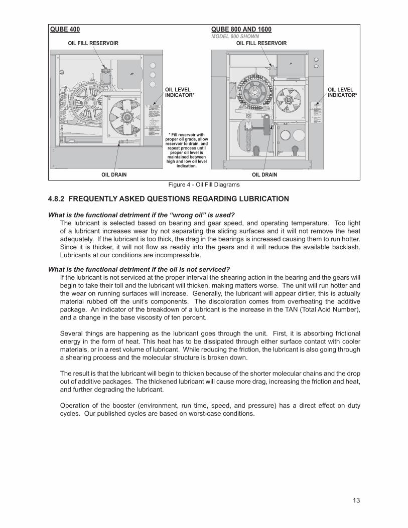
Before starting the unit, fill oil reservoir as instructed below. (see Figure 4 for reference)
1. Pre-measure oil capacity for blower.2. Remove oil fill cap3. Pour oil through fill hole until oil appears in the oil level safety indicator. 4. Slowly bring oil level up to the center of the indicator.5. Allow at least 10 minutes for the oil level to equalize and add or remove as
required.6. Reinstall oil fill cap.
NOTEIt is important to maintain the proper oil level in the blower. Severe damage can occur if the blower is overfilled.
MODEL
OILQUARTSLITERS
Qube 400 0.75 – 10.71 – 0.95
Qube 800 2 – 2.51.9 – 2.4
Qube 1600 5 – 64.7 – 5.7
13
OIL DRAIN
OIL FILL RESERVOIRMODEL 800 SHOWN
OIL LEVELINDICATOR*
OIL DRAIN
OIL FILL RESERVOIR
QUBE 400 QUBE 800 AND 1600
OIL LEVELINDICATOR*
* Fill reservoir with proper oil grade, allow reservoir to drain, and repeat process until
proper oil level is maintained between high and low oil level
indication.
Figure 4 - Oil Fill Diagrams
4.8.2 FREQUENTLY ASKED QUESTIONS REGARDING LUBRICATION
What is the functional detriment if the “wrong oil” is used?The lubricant is selected based on bearing and gear speed, and operating temperature. Too light of a lubricant increases wear by not separating the sliding surfaces and it will not remove the heat adequately. If the lubricant is too thick, the drag in the bearings is increased causing them to run hotter. Since it is thicker, it will not flow as readily into the gears and it will reduce the available backlash. Lubricants at our conditions are incompressible.
What is the functional detriment if the oil is not serviced?If the lubricant is not serviced at the proper interval the shearing action in the bearing and the gears will begin to take their toll and the lubricant will thicken, making matters worse. The unit will run hotter and the wear on running surfaces will increase. Generally, the lubricant will appear dirtier, this is actually material rubbed off the unit’s components. The discoloration comes from overheating the additive package. An indicator of the breakdown of a lubricant is the increase in the TAN (Total Acid Number), and a change in the base viscosity of ten percent.
Several things are happening as the lubricant goes through the unit. First, it is absorbing frictional energy in the form of heat. This heat has to be dissipated through either surface contact with cooler materials, or in a rest volume of lubricant. While reducing the friction, the lubricant is also going through a shearing process and the molecular structure is broken down.
The result is that the lubricant will begin to thicken because of the shorter molecular chains and the drop out of additive packages. The thickened lubricant will cause more drag, increasing the friction and heat, and further degrading the lubricant.
Operation of the booster (environment, run time, speed, and pressure) has a direct effect on duty cycles. Our published cycles are based on worst-case conditions.

14
5. OPERATION
WARNING
Do not operate without guards in place.
WARNINGMaximum operating speed: Table 1 states the maximum operating speed in RPM (rotations per minute), the maximum pressure differential, maximum vacuum and maximum temperature rise. Do not exceed these limits.
WARNINGPhysical harm may occur if human body parts are in contact or exposed to the process pressures or vacuum. Assure that all connections are protected from human contact.
WARNINGIf rated pressure or vacuum levels are exceeded, process fluids will migrate to other parts of the blower and system.
CAUTIONDo not touch hot surfaces.The upper limit of the blower operation is 445º F (229º C). Do not touch the blower while it is in operation and assure blower is cool when not in operation.
CAUTIONDo not stop the blower if there are high outlet pressures in the outlet piping. Unload the outlet piping prior to shutting down the blower.
CAUTIONHearing protection is required while the blower is in operation. Noise levels may exceed 75 dBA.
NOTEThe upper limits are not intended for continuous operation. Consult with factory for detailed information assistance.
15
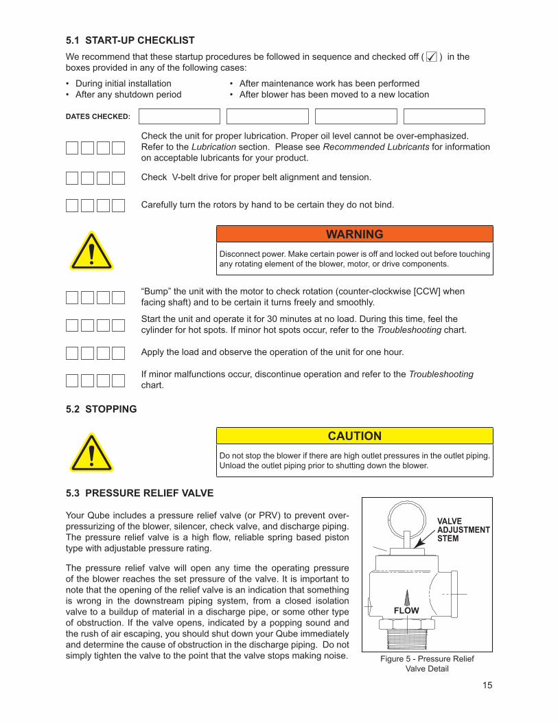
5.1 START-UP CHECKLISTWe recommend that these startup procedures be followed in sequence and checked off ( ) in the boxes provided in any of the following cases:
• During initial installation• After any shutdown period
• After maintenance work has been performed• After blower has been moved to a new location
DATES CHECKED:
Check the unit for proper lubrication. Proper oil level cannot be over-emphasized. Refer to the Lubrication section. Please see Recommended Lubricants for information on acceptable lubricants for your product.
Check V-belt drive for proper belt alignment and tension.
Carefully turn the rotors by hand to be certain they do not bind.
WARNINGDisconnect power. Make certain power is off and locked out before touching any rotating element of the blower, motor, or drive components.
“Bump” the unit with the motor to check rotation (counter-clockwise [CCW] when facing shaft) and to be certain it turns freely and smoothly.
Start the unit and operate it for 30 minutes at no load. During this time, feel the cylinder for hot spots. If minor hot spots occur, refer to the Troubleshooting chart.
Apply the load and observe the operation of the unit for one hour.
If minor malfunctions occur, discontinue operation and refer to the Troubleshooting chart.
5.2 STOPPING
CAUTIONDo not stop the blower if there are high outlet pressures in the outlet piping. Unload the outlet piping prior to shutting down the blower.
5.3 PRESSURE RELIEF VALVE
Your Qube includes a pressure relief valve (or PRV) to prevent over-pressurizing of the blower, silencer, check valve, and discharge piping. The pressure relief valve is a high flow, reliable spring based piston type with adjustable pressure rating.
The pressure relief valve will open any time the operating pressure of the blower reaches the set pressure of the valve. It is important to note that the opening of the relief valve is an indication that something is wrong in the downstream piping system, from a closed isolation valve to a buildup of material in a discharge pipe, or some other type of obstruction. If the valve opens, indicated by a popping sound and the rush of air escaping, you should shut down your Qube immediately and determine the cause of obstruction in the discharge piping. Do not simply tighten the valve to the point that the valve stops making noise. Figure 5 - Pressure Relief
Valve Detail
VALVE ADJUSTMENT STEM
FLOW

16
The recommended setting for the pressure relief valve is 10% greater than the operating gauge pressure of the blower, but not less than 1 PSIG (7 kPa) above the operating gauge pressure of the blower. The valve is set to the proper pressure at the factory, however changes can occur during shipment so it is important that the valve be tested at initial start-up. Setting adjustments may also be necessary when you move your Qube, or if there is a change in process parameters.
If you need to adjust the pressure relief valve setting, follow the procedure shown below:
1. Turn off and lock out power to your Qube. 2. Avoid overtightening of valve during installation. 3. Vacuum setting may be varied approx + or - 10% of original setting by removing hood and running
pressure screw in or out as desired.
NOTE
Retighten locknut after each adjustment
4. Valve may be cleaned by removing disc and cleaning seat surface with a soft cloth. Seating surface may be lapped in case of leakage by using a fine grit compound.
5. Install Qube enclosure panels and secure the 1/4-turn fasteners.6. Unlock the power and start your Qube.
NOTEAs with all standard manufactured discharge silencers supplied with rotary positive displacement blowers, the discharge silencer included with your Qube is of a design that is not ASME code stamped. Local jurisdictions may require any pressure vessel that can experience pressure greater than 14.9 PSIG (1027 mbar g) to be ASME code stamped. Consult your insurance carrier if operation above 14.9 PSIG (1027 mbar g) is required. Please note, this does not apply to Qube 400 as it has an integral silencer.
5.4 ACCESSORIES
(In addition to the following, other accessories are available, please consult factory).
5.4.1 NOISE CONTROL ENCLOSURE
Qube includes a fabricated and insulated sheet steel noise control enclosure designed for the reduction of noise that emanates from the blower and the electric motor.
5.4.2 INTEGRAL SILENCER/BASE
Tuthill has incorporated the discharge silencer into the base to reduce the package size. It also enhances the structural integrity of the base. It has a reactive type silencer that utilizes multiple passes and paths to create sound losses through out-of-phase cancellation of sound waves. NOTE: This applies to Qube 800 & 1600 Only as Qube 400 has an integral blower silencer.
5.4.3 COOLING FAN
Each Qube system is supplied with an axial flow fan driven on the blower shaft, to exhaust heat from the enclosure.

17
5.4.4 AIR FILTER RESTRICTION GAUGE
The air filter restriction gauge included with your Qube is a direct reading gauge designed specifically for use with dry air filters with atmospheric intake. As the filter deteriorates, air inflow will decrease creating increased vacuum between the air filter and the blower. This vacuum is monitored by the air filter restriction gauge, which gives a visual indication of the filter condition.
This feature is particularly useful for blowers operated in dusty environments. Unlike traditional pop-up or latch-up type indicators, the air filter restriction gauge gives constant readout in meaningful terms of the changing condition of your filter.
5.4.5 DISCHARGE PRESSURE GAUGE
The discharge pressure gauge included with your Qube is a diaphragm actuated, direct reading 2 inch (50 mm) dial gauge. The mechanism is enclosed in a steel case that is coated to resist corrosion. A polycarbonate, break-resistant lens and stainless steel bezel protect the gauge from exterior damage. Accuracy and protection from moderate overpressure is assured by a unique, unitized diaphragm chamber. A built-in pulsation dampener stabilizes the indicating needle and is removable for cleaning.
5.4.6 CHECK VALVE
Your Qube includes a discharge swing type check valve designed for minimum pressure loss and positive closure on shutdown. The Qube check valve is a low-loss, swing type check valve. Its ‘T’ pattern design allows for easy maintenance if necessary.
Swing check valves can fail to operate if not properly maintained. Frequently check for damaged, loose, or missing parts. With power off and locked out, hand operate valve to insure springs are in good working order and the flapper seats properly without restriction. Repair or replace valve if problems are encountered. The valve can be removed by removing four screws from sheet metal shroud. Then remove four bolts from check valve housing assembly.
CAUTIONNEVER inspect the valve with your Qube running. This can result in severe damage or injury.
NOTEWe recommend that you inspect the valve monthly by removing the inspection cap and examining the internal workings. Check for wear and hang-up of the flapper mechanism. If flapper drags across body or is restricted in movement, remove valve from service and repair. Apply anti-seize compound to entire mating surface between cap and body to aid removal during subsequent inspections.
NOTEOrientation of the check valve is critical. Inspection cap must be located at the valve top, and the valve direction arrow must be pointed toward the Qube discharge pipe connection and away from the blower. Pointing the check valve direction arrow toward the blower will starve the blower inlet and cause immediate failure.
18
6. MAINTENANCE
DANGERThe blower and parts may contain hazardous media. Assure that blower and parts are evacuated of hazardous media prior to servicing.
CAUTIONThe electrical service must be isolated and de-energized prior to maintenance. Apply appropriate procedures to assure electrical supply is de-energized and cannot be inadvertently energized during maintenance.
Assure piping and product is isolated prior to maintenance of blower. Apply appropriate procedures to assure piping and product is isolated and that inadvertent opening of valves cannot occur during maintenance.
CAUTIONDuring routine maintenance, inspect and assure that guards are in place and secure.
NOTECurrent regulations require Material Safety Data Sheet to be completed and forwarded to Tuthill Corporation on any unit being returned for any reason which has been handling or involved with hazardous gases or materials. This is for the protection of the employees of Tuthill Corporation who are required to perform service on this equipment. Failure to do so will result in service delays.
6.1 OIL INDICATOR, FILL AND DRAIN
The Qube oil can be completely serviced from the front of the machine, see Figure 4. An indicator is provided to show minimum and maximum oil levels. The oil can be drained by removing the drain cap. Oil can be added via the clear plastic reservoir. Check oil level only when the machine is shut-down.
6.2 AIR FILTER
Your Qube is equipped with an air filter (except closed-loop systems) designed for minimum pressure loss and proper filtration of atmospheric inlet air. The air filter element is a disposable pleated paper, radial fin type. We recommend regular replacement of the filter when pressure loss exceeds 15 inches (38 cm) of water column pressure loss.
Optional filter elements (felt, wire mesh, polyester) are available, consult factory.
NOTEDO NOT USE COMPRESSED AIR TO CLEAN THE FILTER ELEMENT. This can result in damage to the filter media and reduce its filtration effectiveness. NEVER operate your Qube without adequate inlet air filtration or unwarrantable damage to the blower can occur.
Remove and replace filter element as follows:
1. Turn off and lock out power to your Qube.2. Remove top panel door. (5/16” hex head wrench required).3. Remove the filter retainer housing nut and washer.4. Remove the filter cover housing off the threaded stud.5. Remove the element off the filter base plate.
19
6. Clean inside of filter base plate and housing as necessary, taking care not to sweep any debris into the blower intake piping.
7. Place a new or cleaned element on the filter base plate.8. Install filter retainer housing with the nut and washer that were removed in step 3. 9. Install Qube enclosure top panel and secure the quarter-turn fasteners.10. Unlock the power and start your Qube.
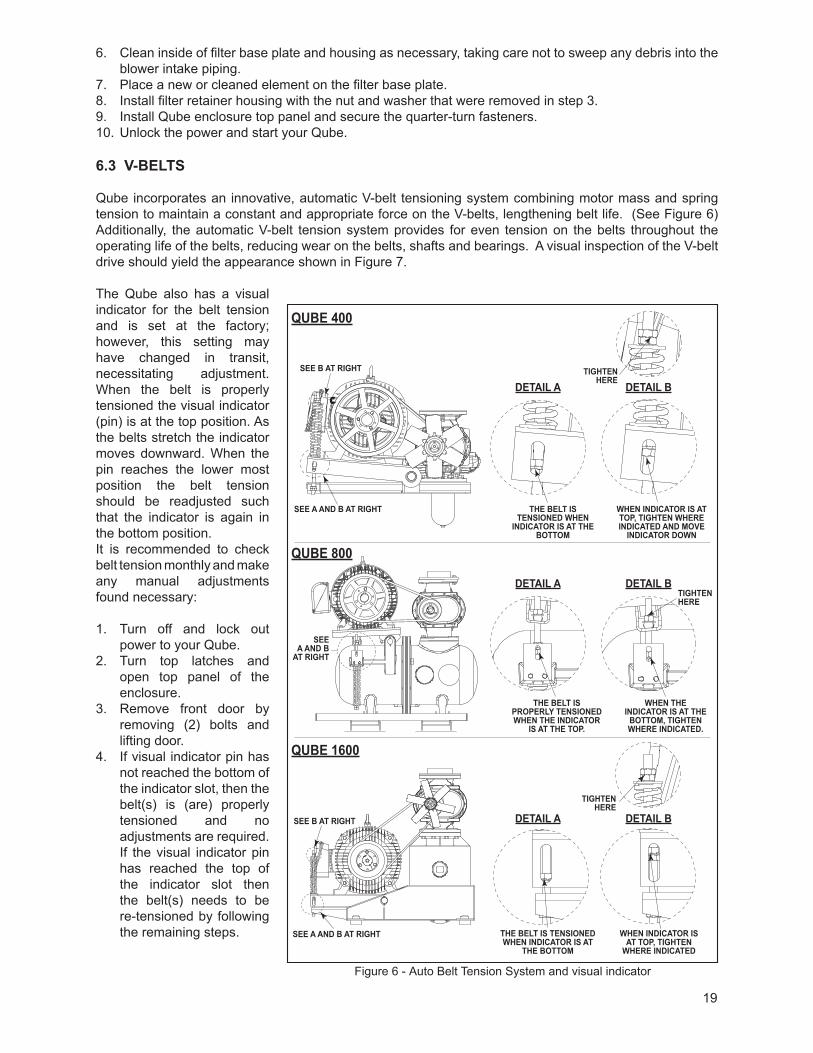
6.3 V-BELTS
Qube incorporates an innovative, automatic V-belt tensioning system combining motor mass and spring tension to maintain a constant and appropriate force on the V-belts, lengthening belt life. (See Figure 6) Additionally, the automatic V-belt tension system provides for even tension on the belts throughout the operating life of the belts, reducing wear on the belts, shafts and bearings. A visual inspection of the V-belt drive should yield the appearance shown in Figure 7.
The Qube also has a visual indicator for the belt tension and is set at the factory; however, this setting may have changed in transit, necessitating adjustment. When the belt is properly tensioned the visual indicator (pin) is at the top position. As the belts stretch the indicator moves downward. When the pin reaches the lower most position the belt tension should be readjusted such that the indicator is again in the bottom position. It is recommended to check belt tension monthly and make any manual adjustments found necessary:
1. Turn off and lock out power to your Qube.
2. Turn top latches and open top panel of the enclosure.
3. Remove front door by removing (2) bolts and lifting door.
4. If visual indicator pin has not reached the bottom of the indicator slot, then the belt(s) is (are) properly tensioned and no adjustments are required. If the visual indicator pin has reached the top of the indicator slot then the belt(s) needs to be re-tensioned by following the remaining steps.
Figure 6 - Auto Belt Tension System and visual indicator
SEEA AND B
AT RIGHT
THE BELT IS PROPERLY TENSIONED WHEN THE INDICATOR
IS AT THE TOP.
WHEN THE INDICATOR IS AT THE
BOTTOM, TIGHTEN WHERE INDICATED.
THE BELT IS TENSIONED WHEN
INDICATOR IS AT THE BOTTOM
SEE A AND B AT RIGHT
SEE A AND B AT RIGHT
SEE B AT RIGHT
SEE B AT RIGHT
WHEN INDICATOR IS AT TOP, TIGHTEN WHERE INDICATED AND MOVE
INDICATOR DOWN
THE BELT IS TENSIONED WHEN INDICATOR IS AT
THE BOTTOM
WHEN INDICATOR IS AT TOP, TIGHTEN
WHERE INDICATED
TIGHTEN HERE
TIGHTEN HERE
TIGHTENHERE
DETAIL A
QUBE 800
QUBE 1600
QUBE 400
DETAIL B
DETAIL A DETAIL B
DETAIL A DETAIL B

20
5. Turn the bottom nuts to tension the belt(s) while holding the top nuts. This action moves the indicator upward. Continue tightening the bottom nuts until the indicator pin is again at the top of the indicator slot.
6. Replace/close and latch the front panel/doors. Lower the top panel and latch.
7. Unlock the power and start your Qube.8. Resume normal operation.
6.4 PREVENTATIVE MAINTENANCE
A good maintenance program will add years of service to your blower. A newly installed blower should be checked frequently during the first month of operation, especially lubrication. Check oil level in both the drive end and gear end of the blower and add oil as needed. Complete oil changes are recommended every 1000 operating hours, or more frequently depending on the type of oil and oil operating temperature. The following is recommended as a minimum maintenance program.
DAILY WEEKLY MONTHLY1. Check and maintain oil level, and add oil as necessary.
2. Check for unusual noise or vibration (See Troubleshooting)
1. Clean all air filters. A clogged air filter can seriously affect the efficiency of the blower and cause overheating and oil increased oil usage. Replace if necessary.
1. Inspect the entire system for leaks.
2. Inspect condition of oil and change if necessary.
3. Check drive belt tension and tighten if necessary.
4. Inspect check valve.
6.5 LONG TERM STORAGE
Any time the blower will be stored for an extended period of time, you should take make sure that it is protected from corrosion by following these steps:
1. Spray the interior (lobes, housing and end plates) with rust preventative. This should be repeated as conditions dictate and at least on a yearly basis.
2. Fill both end covers completely full of oil.3. Firmly attach a very prominent tag stating that the end covers are full of oil and must be drained and
refilled to proper levels prior to startup.4. Apply a rust preventative grease to the drive shaft.5. Spray all exposed surfaces, including the inlet and discharge flanges, with rust preventative.6. Seal inlet, discharge and vent openings. It is not recommended that the unit be set in place, piped to
the system, and allowed to remain idle for a prolonged amount of time. If any component is left open to the atmosphere, the rust preventative will escape and lose its effectiveness.
7. During storage, ensure that the blower does not experience excessive vibration.8. Attach a desiccant bag to either of the covers to prevent condensation from occurring inside the blower.
Make sure any desiccant bag (or bags) is so attached to the covers that they will be removed before startup of the blower.
9. Store the blower in an air conditioned and heated building if at all possible. At least insure as dry conditions as possible.
10. If possible, rotate the drive shaft by hand at least monthly in order to prevent seals from setting in one position.
Too Tight
Slight Bow Too Loose
20/64” = 5/16” (8 mm)
20” (50.8 cm)
8-10 lbs.(3.6-4.5 kg)
Too Tight
Slight Bow Too Loose
20/64” = 5/16” (8 mm)
20” (50.8 cm)
8-10 lbs.(3.6-4.5 kg)
Figure 7 - General appearance of a V-Belt drive
Figure 8 - Setting of proper tension for a V-Belt drive

21
7. TROUBLESHOOTINGAlthough Tuthill Vacuum & Blower Systems blowers are well designed and manufactured, problems may occur due to normal wear and the need for readjustment. The chart below lists symptoms that may occur along with probable causes and remedies.
SYMPTOM PROBABLE CAUSE REMEDIES
Loss of oil
Gear housing not tightened properly Tighten gear housing bolts.
Lip seal failure Disassemble and replace lip seal.
Insufficient sealant Remove gear housing and replace sealant.
Excessive bearing or gear wear
Improper lubrication Correct oil level. Replace dirty oil. See the Lubrication section.
Excessive belt tension Check belt manufacturer’s specifications for tension and adjust accordingly.
Lack of volume
Slipping belts Check belt manufacturer’s specifications for tension and adjust accordingly.
Worn lobe clearances Check for proper clearances.
Speed too low Increase blower speed within limits.
Obstruction in piping Check system to assure an open flow path.
Knocking
Unit out of time Re-time.
Distortion due to improper mounting or pipe strains Check mounting alignment and relieve pipe strains.
Excessive pressure differential
Reduce to manufacturer’s recommended pressure. Examine relief valve and reset if necessary.
Worn gears Replace timing gears. See the Disassembly section.
Excessive operating temperature
Excessive pressure differential Reduce pressure across blower.
Rotor end or tip drag
Insufficient assembled clearances Correct clearances.
Case or frame distortion Check mounting and pipe strain.
Excessive operating pressure Reduce pressure differential.
Excessive operating temperature Reduce pressure differential or reduce inlet temperature.
Vibration
Belt misalignment Check carefully, realign if necessary.
Lobes rubbing Check cylinder for hot spots, then check for lobe contact at these points. Correct clearances.
Worn bearings or gears Check condition of gears and bearings; replace if necessary.
Unbalanced or rubbing lobes Possible buildup on casing or lobes, or inside lobes. Remove buildup and restore clearances.
Driver or blower loose Check mounting and tighten if necessary.
Piping resonance Check pipe supports, check resonance of nearby equipment, check foundation.
Blower rotors out of time Remove blower and check timing.

22
RECOMMENDED MINERAL BASED, FOOD GRADE LUBRICANTS
AMBIENTTEMPERATURE
Lubricant meeting U.S. FDA regulation21 CFR 178.3570 governing petroleum products
which may have incidental contact with food, and USDA H1 requirements
Lubricant meeting U.S. FDA regulations 21 CFR 172.878 and 178.3620(a) for direct
and indirect food contact
0° to 32° F(-18° to 0° C)
CITGO CLARION® A/W 68(ISO 68)
CITGO CLARION® 350 FOOD GRADE(ISO 68)
32° to 90° F(0° to 32° C)
CITGO CLARION® A/W 100(ISO 100) CONSULT FACTORY
90° to 120° F*(32° to 50° C) CONSULT FACTORY CONSULT FACTORY
RECOMMENDED SYNTHETIC BASED, FOOD GRADE LUBRICANTS
AMBIENTTEMPERATURE
Lubricant meeting U.S. FDA regulation21 CFR 178.3570 governing petroleum products
which may have incidental contact with food, and USDA H1 requirements
Lubricant meeting U.S. FDA regulations 21 CFR 172.878 and 178.3620(a) for direct
and indirect food contact
0° to 32° F(-18° to 0° C)
PneuLube™ FG (ISO 100) CONSULT FACTORY32° to 90° F
(0° to 32° C)90° to 120° F*(32° to 50° C)
RECOMMENDED LUBRICANTS FOR M-D VACUUM BOOSTERS(90/91, 92/93, 96, 31/33 AND 35/37 SERIES)
REQUIREMENTS
• Suitable for high vacuum service• 100 cSt @ 40° C• Vapor pressure of 1 micron or less @ 70° F (21° C)• Straight mineral (no additives) or PAO synthetic oil
RECOMMENDED GREASE FOR COMPETITOR® PLUS BLOWERS:TUTHILL CITGO
Tuthill PneuLube™ NLGI #2 premium grade, petroleum base lithium grease.
For food grade requirements: Use Citgo Clarion® Food Grade HTEP grease, NLGI No. 2 grade. It meets all requirements of FDA Regulation 21 CFR 178.3570 (the former USDA H-1 approval requirements) for lubricants having incidental contact with food.
RECOMMENDED LUBRICANTS FOR ROTARY BLOWERS AND VACUUM BOOSTERS RECOMMENDED MINERAL BASED LUBRICANTS
AMBIENTTEMPERATURE SHELL CITGO CHEVRON EXXONMOBIL
0° to 32° F(-18° to 0° C)
TELLUS® S2 M 68(ISO 68)
A/W 68(ISO 68)
RANDO HD 68(ISO 68)
DTE HEAVY MEDIUM(ISO 68)
32° to 90° F(0° to 32° C)
TELLUS® S2 M 100(ISO 100)
A/W 100(ISO 100)
RANDO HD 100(ISO 100)
DTE HEAVY(ISO 100)
90° to 120° F*(32° to 50° C) — A/W 150
(ISO 150)RANDO HD 150
(ISO 150)DTE EXTRA HEAVY
(ISO 150)
RECOMMENDED SYNTHETIC BASED LUBRICANTS**AMBIENT
TEMPERATURE TUTHILL EXXONMOBIL SHELL
0° to 32° F(-18° to 0° C)
PneuLube™ (ISO 100)
SHC 626(ISO 68)
MORLINA® S4 B 68(ISO 68)
32° to 90° F(0° to 32° C)
SHC 627(ISO 100)
MORLINA® S4 B 100(ISO 100)
90° to 120° F*(32° to 50° C)
SHC 629(ISO 150)
MORLINA® S4 B 150(ISO 150)
* For higher ambient temperatures, please consult the factory.
** Blowers used in oxygen-enriched service should use only Castrol Brayco 1726 Plus non-fl ammable, PFPE synthetic lubricant. Blowers used in hydrogen service should use only PneuLube synthetic oil. Tuthill Vacuum & Blower Systems cannot accept responsibility for damage to seals, O-rings and gaskets caused by use of synthetic lubricants not recommended by Tuthill Vacuum and Blower Systems.
8. RECOMMENDED LUBRICANTS

23
NOTES:
24
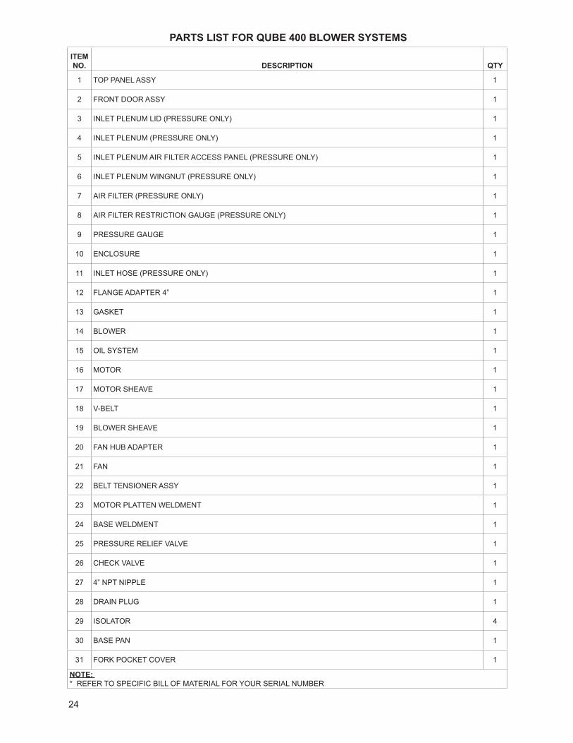
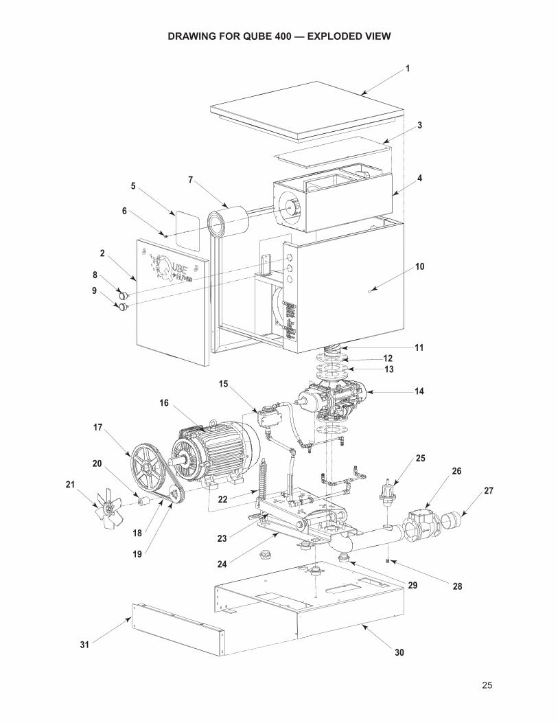
PARTS LIST FOR QUBE 400 BLOWER SYSTEMS
ITEM NO. DESCRIPTION QTY
1 TOP PANEL ASSY 1
2 FRONT DOOR ASSY 1
3 INLET PLENUM LID (PRESSURE ONLY) 1
4 INLET PLENUM (PRESSURE ONLY) 1
5 INLET PLENUM AIR FILTER ACCESS PANEL (PRESSURE ONLY) 1
6 INLET PLENUM WINGNUT (PRESSURE ONLY) 1
7 AIR FILTER (PRESSURE ONLY) 1
8 AIR FILTER RESTRICTION GAUGE (PRESSURE ONLY) 1
9 PRESSURE GAUGE 1
10 ENCLOSURE 1
11 INLET HOSE (PRESSURE ONLY) 1
12 FLANGE ADAPTER 4” 1
13 GASKET 1
14 BLOWER 1
15 OIL SYSTEM 1
16 MOTOR 1
17 MOTOR SHEAVE 1
18 V-BELT 1
19 BLOWER SHEAVE 1
20 FAN HUB ADAPTER 1
21 FAN 1
22 BELT TENSIONER ASSY 1
23 MOTOR PLATTEN WELDMENT 1
24 BASE WELDMENT 1
25 PRESSURE RELIEF VALVE 1
26 CHECK VALVE 1
27 4” NPT NIPPLE 1
28 DRAIN PLUG 1
29 ISOLATOR 4
30 BASE PAN 1
31 FORK POCKET COVER 1
NOTE: * REFER TO SPECIFIC BILL OF MATERIAL FOR YOUR SERIAL NUMBER
25
DRAWING FOR QUBE 400 — EXPLODED VIEW
1
26
2
27
3
28
4
29
5
30
6
31
7
89
10
111213
1415
16
17
18
19
20
2122
23
24
25

26
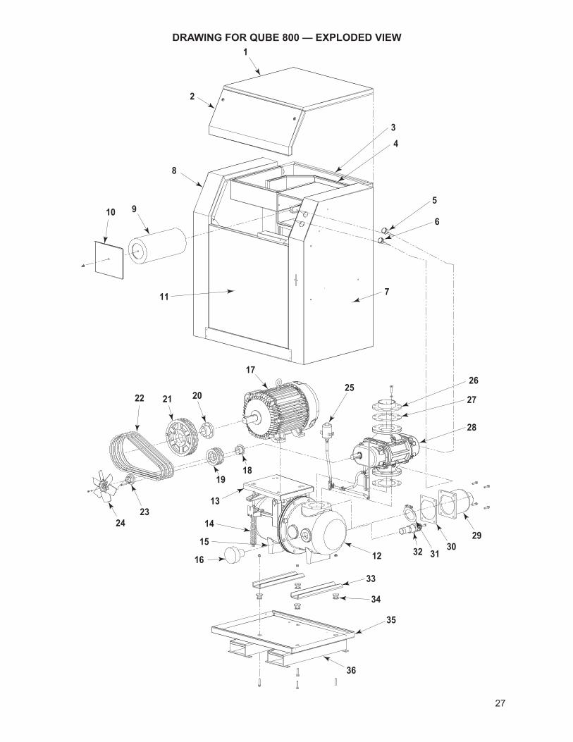
PARTS LIST FOR QUBE 800 BLOWER SYSTEMSITEM NO. DESCRIPTION QTY
1 FOAM TOP PANEL ASSY 1
2 FOAM FRONT DOOR ASSY 1
3 FOAM ENCLOSURE INLET DUCT ASSY 1
4 FOAM INLET PLENUM ASSY 1
5 AIR FILTER RESTRICTION GAUGE 1
6 PRESSURE GAUGE 1
7 FOAM RIGHT PANEL ASSY 1
8 FOAM LEFT PANEL ASSY 1
9 FILTER 1
10 FILTER COVER 1
11 FOAM FRONT PANEL ASSY 1
12 SILENCER, CAST, AIREND, MACHINING 1
13 BELT TENSIONER ASSY 1
14 SILENCER, CAST, MOTOREND, MACHINING 1
15 MOTOR PLATTEN WELDMENT 1
16 UNLOAD VALVE STRATE 1
17 MOTOR 1
18 BUSHING 1
19 SHEAVE 1
20 BUSHING 1
21 SHEAVE 1
22 V-BELT *
23 FAN HUB ADAPTER 1
24 FAN 1
25 RESERVOIR 1
26 FLANGE ADAPTER 6” 1
27 GASKET 2
28 BLOWER 1
29 OUTLET WELDMENT 1
30 GASKET, OUTLET 1
31 VALVE, CHECK 6” 1
32 VALVE, PRESSURE RELIEF 2” 1
33 FOOT, SILENCER BASE 2
34 ISOLATOR, VIBRATION 4
35 PAN, BASE 1
36 RAIL, FORKLIFT 2
NOTE: * REFER TO SPECIFIC BILL OF MATERIAL FOR YOUR SERIAL NUMBER
27
DRAWING FOR QUBE 800 — EXPLODED VIEW1
26
2
27
3
28
4
29
5
30
6
31
7
32
8
33
9
34
10
35
11
36
12
13
14
15
16
17
1819
202122
2324
25
28
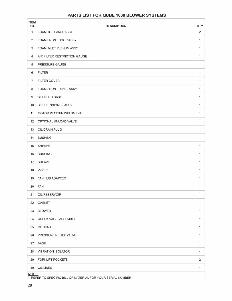
PARTS LIST FOR QUBE 1600 BLOWER SYSTEMSITEM NO. DESCRIPTION QTY
1 FOAM TOP PANEL ASSY 2
2 FOAM FRONT DOOR ASSY 1
3 FOAM INLET PLENUM ASSY 1
4 AIR FILTER RESTRICTION GAUGE 1
5 PRESSURE GAUGE 1
6 FILTER 1
7 FILTER COVER 1
8 FOAM FRONT PANEL ASSY 1
9 SILENCER BASE 1
10 BELT TENSIONER ASSY 1
11 MOTOR PLATTEN WELDMENT 1
12 OPTIONAL UNLOAD VALVE 1
13 OIL DRAIN PLUG 1
14 BUSHING 1
15 SHEAVE 1
16 BUSHING 1
17 SHEAVE 1
18 V-BELT *
19 FAN HUB ADAPTER 1
20 FAN 1
21 OIL RESERVOIR 1
22 GASKET 1
23 BLOWER 1
24 CHECK VALVE ASSEMBLY 1
25 OPTIONAL 1
26 PRESSURE RELIEF VALVE 1
27 BASE 1
28 VIBRATION ISOLATOR 4
29 FORKLIFT POCKETS 2
30 OIL LINES *
NOTE: * REFER TO SPECIFIC BILL OF MATERIAL FOR YOUR SERIAL NUMBER

29
DRAWING FOR QUBE 1600 — EXPLODED VIEW1
26
2
27
3
28
4
29
5
30
67
8
9
10
11
12
13
1415
1617
18
19
20
21
22
23
24
24

30
NOTES:

31
NOTES:

WARRANTY – BLOWER PRODUCTSSubject to the terms and conditions hereinafter set forth and set forth in General Terms of Sale, Tuthill Vacuum & Blower Systems (the Seller) warrants products and parts of its manufacture, when shipped, and its work (including installation and start-up) when performed, will be of good quality and will be free from defects in material and workmanship. This warranty applies only to Seller’s equipment, under use and service in accordance with seller’s written instructions, recommendations and ratings for installation, operating, maintenance and service of products, for a period as stated in the table below. Because of varying conditions of installation and operation, all guarantees of performance are subject to plus or minus 5% variation. (Non-standard materials are subject to a plus or minus 10% variation)
PRODUCTTYPE
TYPE OF APPLICATION
ATMOSPHERIC AIR OR PROCESS AIR WITHOUT LIQUIDS PRESENT
PROCESS GASES OTHER THAN AIR, OR ANY LIQUID INJECTED APPLICATION
New(Qx™ models only)
30 months from date of shipment, or 24 months after initial startup date, whichever occurs first. Consult Factory
New(all other models)
24 months from date of shipment, or 18 months after initial startup date, whichever occurs first
18 months from date of shipment, or 12 months after initial startup date, whichever occurs first
Repair 12 months from date of shipment, or remaining warranty period, whichever is greater
12 months from date of shipment, or remaining warranty period, whichever is greater
THIS WARRANTY EXTENDS ONLY TO BUYER AND/OR ORIGINAL END USER, AND IN NO EVENT SHALL THE SELLER BE LIABLE FOR PROPERTY DAMAGE SUSTAINED BY A PERSON DESIGNATED BY THE LAW OF ANY JURISDICTION AS A THIRD PARTY BENEFICIARY OF THIS WARRANTY OR ANY OTHER WARRANTY HELD TO SURVIVE SELLER’S DISCLAIMER.
All accessories furnished by Seller but manufactured by others bear only that manufacturer’s standard warranty.
All claims for defective products, parts, or work under this warranty must be made in writing immediately upon discovery and, in any event within one (1) year from date of shipment of the applicable item and all claims for defective work must be made in writing immediately upon discovery and in any event within one (1) year from date of completion thereof by Seller. Unless done with prior written consent of Seller, any repairs, alterations or disassembly of Seller’s equipment shall void warranty. Installation and transportation costs are not included and defective items must be held for Seller’s inspection and returned to Seller’s Ex-works point upon request.
THERE ARE NO WARRANTIES, EXPRESSED, IMPLIED OR STATUTORY WHICH EXTEND BEYOND THE DESCRIPTION ON THE FACE HEREOF, INCLUDING WITHOUT LIMITATION, THE IMPLIED WARRANTIES OF MERCHANTABILITY AND FITNESS OF PURPOSE.
After Buyer’s submission of a claim as provided above and its approval, Seller shall at its option either repair or replace its product, part, or work at the original Ex-works point of shipment, or refund an equitable portion of the purchase price.
The products and parts sold hereunder are not warranted for operation with erosive or corrosive material or those which may lead to build up of material within the product supplied, nor those which are incompatible with the materials of construction. The Buyer shall have no claim whatsoever and no product or part shall be deemed to be defective by reason of failure to resist erosive or corrosive action nor for problems resulting from build-up of material within the unit nor for problems due to incompatibility with the materials of construction.
Any improper use, operation beyond capacity, substitution of parts not approved by Seller, or any alteration or repair by others in such manner as in Seller’s judgment affects the product materially and adversely shall void this warranty.
No employee or representative of Seller other than an Officer of the Company is authorized to change this warranty in any way or grant any other warranty. Any such change by an Officer of the Company must be in writing.
The foregoing is Seller’s only obligation and Buyer’s only remedy for breach of warranty, and except for gross negligence, willful misconduct and remedies permitted under the General Terms of Sale in the sections on CONTRACT PERFORMANCE, INSPECTION AND ACCEPTANCE and the PATENTS Clause hereof, the foregoing is BUYER’S ONLY REMEDY HEREUNDER BY WAY OF BREACH OF CONTRACT, TORT OR OTHERWISE, WITHOUT REGARD TO WHETHER ANY DEFECT WAS DISCOVERED OR LATENT AT THE TIME OF DELIVERY OF THE PRODUCT OR WORK. In no event shall Buyer be entitled to incidental or consequential damages. Any action for breach of this agreement must commence within one (1) year after the cause of action has occurred.
May 2008

IMPORTANTAll blowers manufactured by Tuthill Vacuum & Blower Systems are date coded at time of shipment. In order to assure you of the full benefits of the product warranty, please complete, tear out and return the product registration card, or register online at tuthillvacuumblower.com.
OPERATING DATA FORM / PRODUCT REGISTRATIONIt is to the user’s advantage to have the requested data filled in below and available in the event a problem should develop in the blower or the system. This information is also helpful when ordering spare parts.
Model No. V-Belt Size Length
Serial No. Type of Lubrication
Startup Date
Pump RPM Operating Vacuum
Pump SheaveDiameter Any other Special Accessories Supplied or in use:
Motor SheaveDiameter
Motor RPM HP
NOTES:

Tuthill Vacuum & Blower Systems4840 West Kearney StreetSpringfield, Missouri USA 65803-8702O 417.865.8715 800.825.6937 F 417.865.2950tuthillvacuumblower.com Manual 2011 Rev A p/n 2011
For Service & Repair, Technical Support, or Product Sales contact:
INTERNATIONAL QUALITY STANDARD
REGISTERED
VACUUM & BLOWER SYSTEMS
TUTHILL CORPORATION
2/18