wartsila o e w 34df pg kopia
TRANSCRIPT

WÄRTSILÄ 34DF PRODUCT GUIDE


IntroductionThis Product Guide provides data and system proposals for the early design phase of marine engine install-ations. For contracted projects specific instructions for planning the installation are always delivered. Anydata and information herein is subject to revision without notice. This 1/2012 issue replaces all previousissues of the Wärtsilä 34DF Product Guides.
UpdatesPublishedIssue
Chapter Operating Ranges updated and other minor updates1.02.20121/2012
Minor updates throughout the product guide18.11.20113/2011
Chapters Operating Ranges and Fuel System updated15.09.20112/2011
Mechanical propulsion added and several other updates13.09.20111/2011
First issue of Wärtsilä 34DF Product Guide05.06.20091/2009
February 2012
Wärtsilä, Ship Power Technology
THIS PUBLICATION IS DESIGNED TO PROVIDE AS ACCURATE AND AUTHORITATIVE INFORMATION REGARDING THE SUBJECTS COVERED ASWAS AVAILABLE AT THE TIME OF WRITING. HOWEVER, THE PUBLICATION DEALS WITH COMPLICATED TECHNICAL MATTERS AND THE DESIGNOF THE SUBJECT AND PRODUCTS IS SUBJECT TO REGULAR IMPROVEMENTS, MODIFICATIONS AND CHANGES. CONSEQUENTLY, THE PUB-LISHER AND COPYRIGHT OWNER OF THIS PUBLICATION CANNOT TAKE ANY RESPONSIBILITY OR LIABILITY FOR ANY ERRORS OR OMISSIONSIN THIS PUBLICATION OR FOR DISCREPANCIES ARISING FROM THE FEATURES OF ANY ACTUAL ITEM IN THE RESPECTIVE PRODUCT BEINGDIFFERENT FROM THOSE SHOWN IN THIS PUBLICATION. THE PUBLISHER AND COPYRIGHT OWNER SHALL NOT BE LIABLE UNDER ANY CIR-CUMSTANCES, FOR ANY CONSEQUENTIAL, SPECIAL, CONTINGENT, OR INCIDENTAL DAMAGES OR INJURY, FINANCIAL OR OTHERWISE,SUFFERED BY ANY PART ARISING OUT OF, CONNECTED WITH, OR RESULTING FROM THE USE OF THIS PUBLICATION OR THE INFORMATIONCONTAINED THEREIN.
COPYRIGHT © 2012 BY WÄRTSILÄ FINLAND Oy
ALL RIGHTS RESERVED. NO PART OF THIS PUBLICATION MAY BE REPRODUCED OR COPIED IN ANY FORM OR BY ANY MEANS, WITHOUT PRIORWRITTEN PERMISSION OF THE COPYRIGHT OWNER.
Product Guide Wärtsilä 34DF - 1/2012 iii
Product GuideIntroduction

Table of Contents
11. Main Data and Outputs .............................................................................................................................11.1 Technical main data ..........................................................................................................................11.2 Maximum continuous output ............................................................................................................21.3 Derating of output in gas mode ........................................................................................................41.4 Reference conditions ........................................................................................................................41.5 Operation in inclined position ..........................................................................................................51.6 Principal dimensions and weights ....................................................................................................
82. Operating Ranges .....................................................................................................................................82.1 Engine operating range ....................................................................................................................92.2 Loading capacity ..............................................................................................................................
112.3 Operation at low load and idling .......................................................................................................122.4 Low air temperature ........................................................................................................................
133. Technical Data ...........................................................................................................................................133.1 Wärtsilä 6L34DF ...............................................................................................................................153.2 Wärtsilä 9L34DF ...............................................................................................................................173.3 Wärtsilä 12V34DF ............................................................................................................................193.4 Wärtsilä 16V34DF ............................................................................................................................
214. Description of the Engine .........................................................................................................................214.1 Definitions .........................................................................................................................................214.2 Main components and systems ........................................................................................................264.3 Cross section of the engine ..............................................................................................................284.4 Overhaul intervals and expected life times .......................................................................................
295. Piping Design, Treatment and Installation ..............................................................................................295.1 Pipe dimensions ...............................................................................................................................305.2 Trace heating ....................................................................................................................................305.3 Operating and design pressure ........................................................................................................315.4 Pipe class .........................................................................................................................................315.5 Insulation ..........................................................................................................................................315.6 Local gauges ....................................................................................................................................325.7 Cleaning procedures ........................................................................................................................325.8 Flexible pipe connections .................................................................................................................335.9 Clamping of pipes .............................................................................................................................
356. Fuel System ...............................................................................................................................................356.1 Acceptable fuel characteristics .........................................................................................................416.2 Operating principles .........................................................................................................................426.3 Fuel gas system ...............................................................................................................................486.4 Fuel oil system .................................................................................................................................
677. Lubricating Oil System .............................................................................................................................677.1 Lubricating oil requirements .............................................................................................................687.2 Internal lubricating oil system ...........................................................................................................717.3 External lubricating oil system ..........................................................................................................767.4 Crankcase ventilation system ...........................................................................................................777.5 Flushing instructions ........................................................................................................................
788. Compressed Air System ...........................................................................................................................788.1 Instrument air quality ........................................................................................................................788.2 Internal compressed air system .......................................................................................................818.3 External compressed air system ......................................................................................................
849. Cooling Water System ..............................................................................................................................849.1 Water quality ...................................................................................................................................859.2 Internal cooling water system ...........................................................................................................
iv Product Guide Wärtsilä 34DF - 1/2012
Product GuideTable of Contents

889.3 External cooling water system ..........................................................................................................
9710. Combustion Air System ...........................................................................................................................9710.1 Engine room ventilation ....................................................................................................................9810.2 Combustion air system design .........................................................................................................
10011. Exhaust Gas System .................................................................................................................................10011.1 Internal exhaust gas system .............................................................................................................10211.2 Exhaust gas outlet ............................................................................................................................10411.3 External exhaust gas system ...........................................................................................................
10812. Turbocharger Cleaning .............................................................................................................................10812.1 Turbine cleaning system ...................................................................................................................10812.2 Compressor cleaning system ...........................................................................................................
10913. Exhaust Emissions ...................................................................................................................................10913.1 Dual fuel engine exhaust components .............................................................................................10913.2 Marine exhaust emissions legislation ...............................................................................................11213.3 Methods to reduce exhaust emissions .............................................................................................
11314. Automation System ..................................................................................................................................11314.1 UNIC C3 ...........................................................................................................................................11814.2 Functions ..........................................................................................................................................12214.3 Alarm and monitoring signals ...........................................................................................................12214.4 Electrical consumers ........................................................................................................................
12515. Foundation .................................................................................................................................................12515.1 Steel structure design ......................................................................................................................12515.2 Mounting of main engines ................................................................................................................13715.3 Mounting of generating sets .............................................................................................................14015.4 Flexible pipe connections .................................................................................................................
14116. Vibration and Noise ..................................................................................................................................14116.1 External forces and couples .............................................................................................................14216.2 Torque variations ..............................................................................................................................14216.3 Mass moments of inertia ..................................................................................................................14216.4 Air borne noise .................................................................................................................................14316.5 Exhaust noise ...................................................................................................................................
14517. Power Transmission .................................................................................................................................14517.1 Flexible coupling ...............................................................................................................................14617.2 Torque flange ....................................................................................................................................14617.3 Clutch ...............................................................................................................................................14617.4 Shaft locking device ..........................................................................................................................14717.5 Power-take-off from the free end ......................................................................................................14817.6 Input data for torsional vibration calculations ...................................................................................14917.7 Turning gear .....................................................................................................................................
15018. Engine Room Layout ................................................................................................................................15018.1 Crankshaft distances ........................................................................................................................15718.2 Space requirements for maintenance ..............................................................................................15718.3 Transportation and storage of spare parts and tools ........................................................................15718.4 Required deck area for service work ................................................................................................
16019. Transport Dimensions and Weights ........................................................................................................16019.1 Lifting of main engines .....................................................................................................................16219.2 Lifting of generating sets ..................................................................................................................16319.3 Engine components ..........................................................................................................................
16520. Product Guide Attachments .....................................................................................................................
16621. ANNEX ........................................................................................................................................................
Product Guide Wärtsilä 34DF - 1/2012 v
Product GuideTable of Contents

16621.1 Unit conversion tables ......................................................................................................................16721.2 Collection of drawing symbols used in drawings ..............................................................................
vi Product Guide Wärtsilä 34DF - 1/2012
Product GuideTable of Contents

1. Main Data and Outputs
1.1 Technical main dataThe Wärtsilä 34DF is a 4-stroke, non-reversible, turbocharged and inter-cooled dual fuel engine with directinjection of liquid fuel and indirect injection of gas fuel. The engine can be operated in gas mode or indiesel mode.
340 mmCylinder bore ..............................
400 mmStroke ..........................................
36.3 l/cylPiston displacement ...................
2 inlet valves and 2 exhaust valvesNumber of valves ........................
6 and 9 in-line; 12 and 16 in V-formCylinder configuration .................
clockwise, counterclockwise on requestDirection of rotation ....................
720, 750 rpmSpeed ..........................................
9.6, 10.0 m/sMean piston speed .....................
1.2 Maximum continuous outputTable 1.1 Rating table for Wärtsilä 34DF
Generating setsMain engines750 rpmCylinder
configuration750 rpm720 rpm
Generator [kVA]Engine [kW]Generator [kVA]Engine [kW]Engine [kW]
32402700313026102700Wärtsilä 6L34DF
48604050470039154050Wärtsilä 9L34DF
64805400626052205400Wärtsilä 12V34DF
86407200835069607200Wärtsilä 16V34DF
The mean effective pressure Pe can be calculated using the following formula:
where:
mean effective pressure [bar]Pe =
output per cylinder [kW]P =
engine speed [r/min]n =
cylinder diameter [mm]D =
length of piston stroke [mm]L =
operating cycle (4)c =
Product Guide Wärtsilä 34DF - 1/2012 1
Product Guide1. Main Data and Outputs

1.3 Derating of output in gas mode
1.3.1 Derating due to methane number and charge air receiver temperatureFigure 1.1 Derating due to methane number and charge air receiver temperature
NOTE! Compensating a low methane number gas by lowering the charge air receiver temperature below45 °C is not allowed.
Minimum charge air receiver temperature is 35°C.
Compensating a higher charge air receiver temperature than 55 °C by a high methane numbergas is not allowed.
The dew point shall be calculated for the specific site conditions. The minimum charge air re-ceiver temperature shall be above the dew point, otherwise condensation will occur in the chargeair cooler.
Each +10 °C higher charge air receiver temperature from 45 °C means a 18 kPa higher chargeair pressure. This will have influence on the KGAS derating and on the KTC derating calculation.
The charge air receiver temperature is approximately 5-10 °C higher than the charge air coolanttemperature at rated load.
Glycol usage in cooling water according to document DAAE062266.
2 Product Guide Wärtsilä 34DF - 1/2012
Product Guide1. Main Data and Outputs

1.3.2 Derating of output for site ambient conditionsFigure 1.2 Derating of output for gas feed pressure and LHV
NOTE! The above given values for gas feed pressure is before the engine (after the gas regulating unit).
No compensation (uprating) of the engine output is allowed, neither for gas feed pressure higherthan required in the graph above nor lower heating value above 36 MJ/m3
N .
Values are given in m3N is at 0 °C and 101.3 kPa.
If the gas pressure is lower than required, a pressure booster unit can be installed before thegas regulating unit to ensure adequate gas pressure. If pressure arise is not possible the engineoutput has to be adjusted according to above.
A 18 kPa higher gas feed pressure is required per 10 °C higher charge air receiver temperature,due to increased charge air pressure.
Product Guide Wärtsilä 34DF - 1/2012 3
Product Guide1. Main Data and Outputs

1.4 Reference conditionsThe output is available within a range of ambient conditions and coolant temperatures specified in thechapter Technical Data. The required fuel quality for maximum output is specified in the section Fuel char-acteristics. For ambient conditions or fuel qualities outside the specification, the output may have to bereduced.
The specific fuel consumption is stated in the chapter Technical Data. The statement applies to enginesoperating in ambient conditions according to ISO 3046-1:2002 (E).
100 kPatotal barometric pressure
25°Cair temperature
30%relative humidity
25°Ccharge air coolant temperature
Correction factors for the fuel oil consumption in other ambient conditions are given in standard ISO 3046-1:2002.
1.5 Operation in inclined positionMax. inclination angles at which the engine will operate satisfactorily.
15°Transverse inclination, permanent (list) ..................
22.5°Transverse inclination, momentary (roll) .................
10°Longitudinal inclination, permanent (trim) ...............
10°Longitudinal inclination, momentary (pitch) ............
4 Product Guide Wärtsilä 34DF - 1/2012
Product Guide1. Main Data and Outputs

1.6 Principal dimensions and weights
1.6.1 Main enginesFigure 1.3 In-line engines (DAAE082421A)
LE4LE2HE3HE4HE2WE1HE1LE1Engine
250367011555002345238525505280Wärtsilä 6L34DF
250514011555002345238525506750Wärtsilä 9L34DF
WeightWE3LE5WE6HE6HE5LE3WE5WE2Engine
33.38805053607101780114514251350Wärtsilä 6L34DF
46.88805053604201780115014251350Wärtsilä 9L34DF
All dimensions are in mm. Weight in metric tons with liquids (wet oil sump) but without flywheel.
Product Guide Wärtsilä 34DF - 1/2012 5
Product Guide1. Main Data and Outputs

Figure 1.4 V-engines (DAAE082423B)
WE3LE4LE2HE3HE4HE2WE1HE1LE1Engine
1225300415012106502120302026606615Wärtsilä 12V34DF
1225300527012106502120302023357735Wärtsilä 16V34DF
WeightWE2LE5WE6HE6HE5WE4LE3WE5Engine
56.11590590600710191585017351510Wärtsilä 12V34DF
70.71590590600420191585017351510Wärtsilä 16V34DF
All dimensions are in mm. Weight in metric tons with liquids (wet oil sump) but without flywheel.
6 Product Guide Wärtsilä 34DF - 1/2012
Product Guide1. Main Data and Outputs

1.6.2 Generating setsFigure 1.5 In-line engines (DAAE082427)
Figure 1.6 V engines (DAAE082975)
Weight**HA4HA3HA2HA1WA3WA2WA1LA4**LA3LA2**LA1**Engine
5710551450234540001600191022903160115069008700W 6L34DF
84105516302345418022002510289038451150885010475W 9L34DF
96137517002120436522002620306037751735795510075W 12V34DF
121137518502120451522002620306037651735902011175W 16V34DF
** Dependent on generator and flexible coupling.
All dimensions in mm. Weight in metric tons with liquids.
Product Guide Wärtsilä 34DF - 1/2012 7
Product Guide1. Main Data and Outputs

2. Operating Ranges
2.1 Engine operating rangeBelow nominal speed the load must be limited according to the diagrams in this chapter in order to maintainengine operating parameters within acceptable limits. Operation in the shaded area is permitted only tem-porarily during transients. Minimum speed is indicated in the diagram, but project specific limitations mayapply.
2.1.1 Controllable pitch propellersAn automatic load control system is required to protect the engine from overload. The load control reducesthe propeller pitch automatically, when a pre-programmed load versus speed curve (“engine limit curve”)is exceeded, overriding the combinator curve if necessary. Engine load is determined from measured shaftpower and actual engine speed. The shaft power meter is Wärtsilä supply.
The propulsion control must also include automatic limitation of the load increase rate. Maximum loadingrates can be found later in this chapter.
The propeller efficiency is highest at design pitch. It is common practice to dimension the propeller so thatthe specified ship speed is attained with design pitch, nominal engine speed and 85% output in the specifiedloading condition. The power demand from a possible shaft generator or PTO must be taken into account.The 15% margin is a provision for weather conditions and fouling of hull and propeller. An additional enginemargin can be applied for most economical operation of the engine, or to have reserve power.
Figure 2.1 Operating field for CP Propeller, 450 kW/cyl, rated speed 750 rpm
8 Product Guide Wärtsilä 34DF - 1/2012
Product Guide2. Operating Ranges

Remarks: The maximum output may have to be reduced depending on gas properties and gas pressure,refer to section "Derating of output in gas mode". The permissible output will in such case be reduced withsame percentage at all revolution speeds.
Restrictions for low load operation to be observed.
2.2 Loading capacityControlled load increase is essential for highly supercharged engines, because the turbocharger needstime to accelerate before it can deliver the required amount of air. Sufficient time to achieve even temper-ature distribution in engine components must also be ensured. Dual fuel engines operating in gas moderequire precise control of the air/fuel ratio, which makes controlled load increase absolutely decisive forproper operation on gas fuel.
The loading ramp “preheated, normal gas” (see figures) can be used as the default loading rate for bothdiesel and gas mode. If the control system has only one load increase ramp, then the ramp for a preheatedengine must be used. The HT-water temperature in a preheated engine must be at least 60ºC, preferably70ºC, and the lubricating oil temperature must be at least 40ºC.
The loading ramp “max. capacity gas” indicates the maximum capability of the engine in gas mode. Fasterloading may result in alarms, knock and undesired trips to diesel. This ramp can also be used as normalloading rate in diesel mode once the engine has attained normal operating temperature.
The maximum loading rate “emergency diesel” is close to the maximum capability of the engine in dieselmode. It shall not be used as the normal loading rate in diesel mode.
The load should always be applied gradually in normal operation. Acceptable load increments are smallerin gas mode than in diesel mode and also smaller at high load, which must be taken into account in applic-ations with sudden load changes. The time between load increments must be such that the maximumloading rate is not exceeded. In the case of electric power generation, the classification society shall becontacted at an early stage in the project regarding system specifications and engine loading capacity.
Electric generators must be capable of 10% overload. The maximum engine output is 110% in diesel modeand 100% in gas mode. Transfer to diesel mode takes place automatically in case of overload. Lower thanspecified methane number may also result in automatic transfer to diesel when operating close to 100%output. Expected variations in gas fuel quality and momentary load level must be taken into account toensure that gas operation can be maintained in normal operation.
Product Guide Wärtsilä 34DF - 1/2012 9
Product Guide2. Operating Ranges

2.2.1 Mechanical propulsion, controllable pitch propeller (CPP)Figure 2.2 Maximum load increase rates for variable speed engines
The propulsion control must not permit faster load reduction than 20 s from 100% to 0% without automatictransfer to diesel first.
2.2.2 Electric propulsionFigure 2.3 Increasing load successively from 0 to 100% MCR
The propulsion control and the power management system must not permit faster load reduction than 20s from 100% to 0% without automatic transfer to diesel first.
10 Product Guide Wärtsilä 34DF - 1/2012
Product Guide2. Operating Ranges

In electric propulsion applications loading ramps are implemented both in the propulsion control and in thepower management system, or in the engine speed control in case isochronous load sharing is applied.When the load sharing is based on speed droop, it must be taken into account that the load increase rateof a recently connected generator is the sum of the load transfer performed by the power managementsystem and the load increase performed by the propulsion control.
Maximum instant load steps
The electrical system must be designed so that tripping of breakers can be safely handled. This requiresthat the engines are protected from load steps exceeding their maximum load acceptance capability. Iffast load shedding is complicated to implement or undesired, the instant load step capacity can be increasedwith a fast acting signal that requests transfer to diesel mode.
Gas mode
• Maximum step-wise load increases according to figure
• Steady-state frequency band ≤ 1.5 %
• Maximum speed drop 10 %
• Recovery time ≤ 10 s
• Time between load steps of maximum size ≥ 15 s
• Maximum step-wise load reductions: 100-75-45-0%
Diesel mode
• Maximum step-wise load increase 33% of MCR
• Steady-state frequency band ≤ 1.0 %
• Maximum speed drop 10 %
• Recovery time ≤ 5 s
• Time between load steps of maximum size ≥ 8 s
Start-up
A stand-by generator reaches nominal speed in 50-70 seconds after the start signal (check of pilot fuel in-jection is always performed during a normal start).
With black-out start active nominal speed is reached in about 25 s (pilot fuel injection disabled).
The engine can be started with gas mode selected. It will then start using gas fuel as soon as the pilotcheck is completed and the gas supply system is ready.
Start and stop on heavy fuel is not restricted.
2.3 Operation at low load and idling
Absolute idling (declutched main engine, disconnected generator):
• Maximum 10 minutes if the engine is to be stopped after the idling. 3-5 minutes idling before stop isrecommended.
• Maximum 6 hours if the engine is to be loaded after the idling.
Operation below 20 % load on HFO or below 10 % load on MDF or gas
• Maximum 100 hours continuous operation. At intervals of 100 operating hours the engine must beloaded to minimum 70 % of the rated output.
Operation above 20 % load on HFO or above 10 % load on MDF or gas
• No restrictions.
Product Guide Wärtsilä 34DF - 1/2012 11
Product Guide2. Operating Ranges
2.4 Low air temperatureIn cold conditions the following minimum inlet air temperatures apply:
Gas mode:
• + 5ºC
Diesel mode:
• Starting + 5ºC
• Idling - 5ºC
• High load - 10ºC
The two-stage charge air cooler is useful for heating of the charge air during prolonged low load operationin cold conditions. Sustained operation between 0 and 40% load can however require special provisionsin cold conditions to prevent too low HT-water temperature. If necessary, the preheating arrangement canbe designed to heat the running engine (capacity to be checked).
For further guidelines, see chapter Combustion air system design.
12 Product Guide Wärtsilä 34DF - 1/2012
Product Guide2. Operating Ranges
3. Technical Data
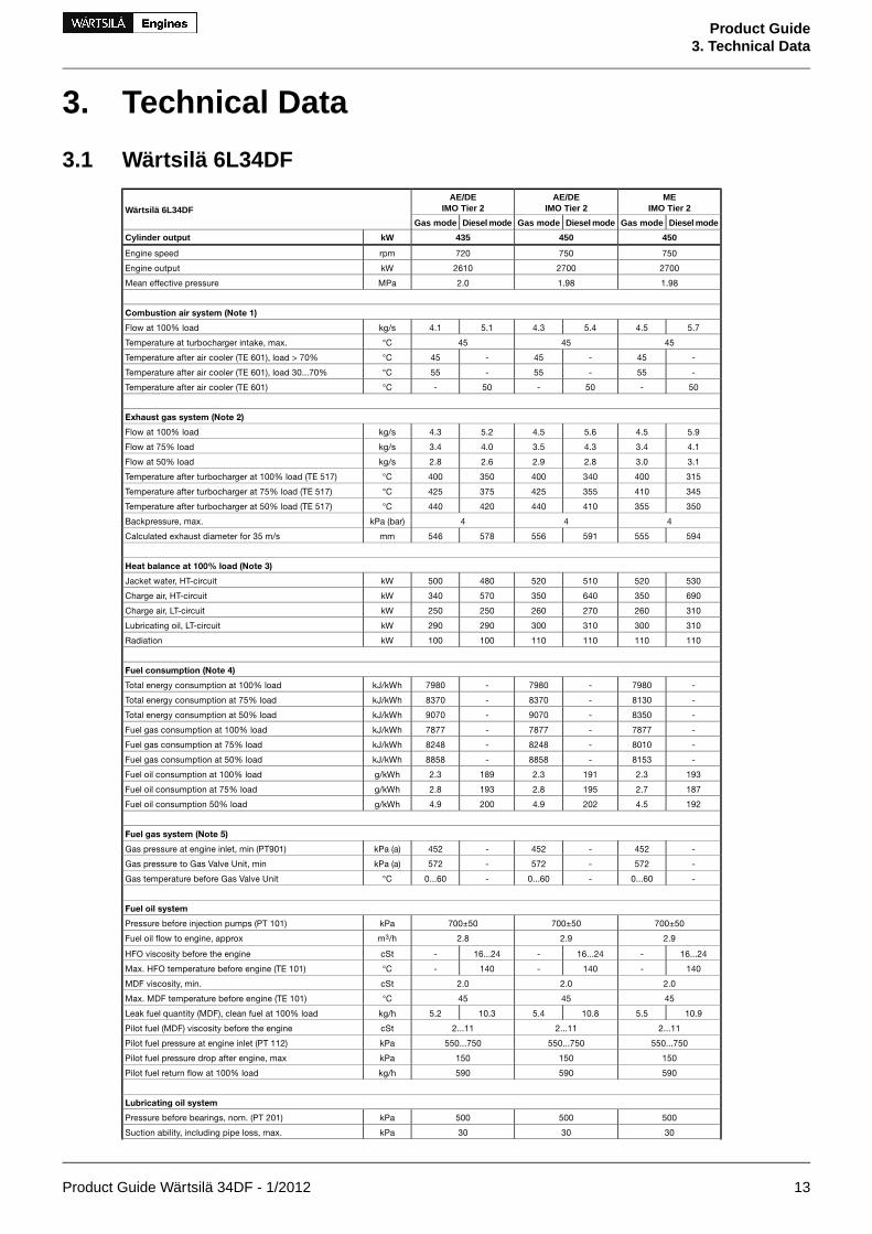
3.1 Wärtsilä 6L34DF
MEIMO Tier 2
AE/DEIMO Tier 2
AE/DEIMO Tier 2Wärtsilä 6L34DF
Diesel modeGas modeDiesel modeGas modeDiesel modeGas mode
450450435kWCylinder output
750750720rpmEngine speed
270027002610kWEngine output
1.981.982.0MPaMean effective pressure
Combustion air system (Note 1)
5.74.55.44.35.14.1kg/sFlow at 100% load
454545°CTemperature at turbocharger intake, max.
-45-45-45°CTemperature after air cooler (TE 601), load > 70%
-55-55-55°CTemperature after air cooler (TE 601), load 30...70%
50-50-50-°CTemperature after air cooler (TE 601)
Exhaust gas system (Note 2)
5.94.55.64.55.24.3kg/sFlow at 100% load
4.13.44.33.54.03.4kg/sFlow at 75% load
3.13.02.82.92.62.8kg/sFlow at 50% load
315400340400350400°CTemperature after turbocharger at 100% load (TE 517)
345410355425375425°CTemperature after turbocharger at 75% load (TE 517)
350355410440420440°CTemperature after turbocharger at 50% load (TE 517)
444kPa (bar)Backpressure, max.
594555591556578546mmCalculated exhaust diameter for 35 m/s
Heat balance at 100% load (Note 3)
530520510520480500kWJacket water, HT-circuit
690350640350570340kWCharge air, HT-circuit
310260270260250250kWCharge air, LT-circuit
310300310300290290kWLubricating oil, LT-circuit
110110110110100100kWRadiation
Fuel consumption (Note 4)
-7980-7980-7980kJ/kWhTotal energy consumption at 100% load
-8130-8370-8370kJ/kWhTotal energy consumption at 75% load
-8350-9070-9070kJ/kWhTotal energy consumption at 50% load
-7877-7877-7877kJ/kWhFuel gas consumption at 100% load
-8010-8248-8248kJ/kWhFuel gas consumption at 75% load
-8153-8858-8858kJ/kWhFuel gas consumption at 50% load
1932.31912.31892.3g/kWhFuel oil consumption at 100% load
1872.71952.81932.8g/kWhFuel oil consumption at 75% load
1924.52024.92004.9g/kWhFuel oil consumption 50% load
Fuel gas system (Note 5)
-452-452-452kPa (a)Gas pressure at engine inlet, min (PT901)
-572-572-572kPa (a)Gas pressure to Gas Valve Unit, min
-0...60-0...60-0...60°CGas temperature before Gas Valve Unit
Fuel oil system
700±50700±50700±50kPaPressure before injection pumps (PT 101)
2.92.92.8m3/hFuel oil flow to engine, approx
16...24-16...24-16...24-cStHFO viscosity before the engine
140-140-140-°CMax. HFO temperature before engine (TE 101)
2.02.02.0cStMDF viscosity, min.
454545°CMax. MDF temperature before engine (TE 101)
10.95.510.85.410.35.2kg/hLeak fuel quantity (MDF), clean fuel at 100% load
2...112...112...11cStPilot fuel (MDF) viscosity before the engine
550...750550...750550...750kPaPilot fuel pressure at engine inlet (PT 112)
150150150kPaPilot fuel pressure drop after engine, max
590590590kg/hPilot fuel return flow at 100% load
Lubricating oil system
500500500kPaPressure before bearings, nom. (PT 201)
303030kPaSuction ability, including pipe loss, max.
Product Guide Wärtsilä 34DF - 1/2012 13
Product Guide3. Technical Data

MEIMO Tier 2
AE/DEIMO Tier 2
AE/DEIMO Tier 2Wärtsilä 6L34DF
Diesel modeGas modeDiesel modeGas modeDiesel modeGas mode
450450435kWCylinder output
505050kPaPriming pressure, nom. (PT 201)
303030kPaSuction ability priming pump, including pipe loss, max.
636363°CTemperature before bearings, nom. (TE 201)
787878°CTemperature after engine, approx.
818178m3/hPump capacity (main), engine driven
707067m3/hPump capacity (main), electrically driven
15.0 / 18.015.0 / 18.015.0 / 18.0m3/hPriming pump capacity (50/60Hz)
333m3Oil volume in separate system oil tank
0.40.40.4g/kWhOil consumption at 100% load, approx.
0.30.30.3kPaCrankcase ventilation backpressure, max.
8.5...9.58.5...9.58.5...9.5lOil volume in turning device
1.4...2.21.4...2.21.4...2.2lOil volume in speed governor
HT cooling water system
250 + static250 + static250 + statickPaPressure at engine, after pump, nom. (PT 401)
450450450kPaPressure at engine, after pump, max. (PT 401)
858585°CTemperature before cylinders, approx. (TE 401)
969696°CTemperature after engine, nom.
606060m3/hCapacity of engine driven pump, nom.
100100100kPaPressure drop over engine, total
150 (1.5)150 (1.5)150 (1.5)kPaPressure drop in external system, max.
70...15070...15070...150kPaPressure from expansion tank
0.410.410.41m3Water volume in engine
250250250kPaDelivery head of stand-by pump
LT cooling water system
250+ static250+ static250+ statickPaPressure at engine, after pump, nom. (PT 471)
450450450kPaPressure at engine, after pump, max. (PT 471)
383838°CTemperature before engine, max. (TE 471)
252525°CTemperature before engine, min. (TE 471)
606060m3/hCapacity of engine driven pump, nom.
353535kPaPressure drop over charge air cooler
200 (2.0)200 (2.0)200 (2.0)kPaPressure drop in external system, max.
70...15070...15070...150kPaPressure from expansion tank
250250250kPaDelivery head of stand-by pump
Starting air system
300030003000kPaPressure, nom. (PT 301)
150015001500kPaPressure at engine during start, min. (20 °C)
300030003000kPaPressure, max. (PT 301)
160016001600kPaLow pressure limit in starting air receiver
0.70.70.7Nm3Consumption per start at 20 °C (successful start)
3.53.53.5Nm3Consumption per start at 20 °C (with slowturn)
Notes:
At Gas LHV 49620kJ/kgNote 1
At ISO 3046-1 conditions (ambient air temperature 25°C, LT-water 25°C) and 100% load. Flow tolerance 5% and temperature tolerance 10°C in gas mode operation.Flow tolerance 8% and temperature tolerance 15°C in diesel mode operation.
Note 2
At 100% output and nominal speed. The figures are valid for ambient conditions according to ISO 3046/1, except for LT-water temperature, which is correspondingto charge air receiver temperature 45ºC in gas operation. With engine driven water and lubricating oil pumps. Tolerance for cooling water heat 10%, tolerance forradiation heat 30%. Fouling factors and a margin to be taken into account when dimensioning heat exchangers.
Note 3
At ambient conditions according to ISO 3046/1, fuel net calorific value 42700 kJ/kg, with engine driven pumps (two cooling water + one lubricating oil pumps).Tolerance 5%.
Note 4
Fuel gas pressure given at LHV ≥ 36MJ/m³N. Required fuel gas pressure depends on fuel gas LHV and need to be increased for lower LHV's. Pressure drop inexternal fuel gas system to be considered. See chapter Fuel system for further information.
Note 5
ME = Engine driving propeller, variable speed
AE = Auxiliary engine driving generator
DE = Diesel-Electric engine driving generator
Subject to revision without notice.
14 Product Guide Wärtsilä 34DF - 1/2012
Product Guide3. Technical Data

3.2 Wärtsilä 9L34DF
MEIMO Tier 2
AE/DEIMO Tier 2
AE/DEIMO Tier 2Wärtsilä 9L34DF
Diesel modeGas modeDiesel modeGas modeDiesel modeGas mode
450450435kWCylinder output
750750720rpmEngine speed
405040503915kWEngine output
1.981.982.0MPaMean effective pressure
Combustion air system (Note 1)
8.66.78.16.47.66.2kg/sFlow at 100% load
454545°CTemperature at turbocharger intake, max.
-45-45-45°CTemperature after air cooler (TE 601), load > 70%
-55-55-55°CTemperature after air cooler (TE 601), load 30...70%
50-50-50-°CTemperature after air cooler (TE 601)
Exhaust gas system (Note 2)
8.86.78.36.77.86.5kg/sFlow at 100% load
6.25.16.55.36.05.1kg/sFlow at 75% load
4.74.44.24.34.04.2kg/sFlow at 50% load
315400340400350400°CTemperature after turbocharger at 100% load (TE 517)
345410355425375425°CTemperature after turbocharger at 75% load (TE 517)
350355410440420440°CTemperature after turbocharger at 50% load (TE 517)
444kPa (bar)Backpressure, max.
727680724680707670mmCalculated exhaust diameter for 35 m/s
Heat balance at 100% load (Note 3)
800780760780730760kWJacket water, HT-circuit
1030530880530860500kWCharge air, HT-circuit
470390410400380380kWCharge air, LT-circuit
470450460450430440kWLubricating oil, LT-circuit
160160160160160150kWRadiation
Fuel consumption (Note 4)
-7980-7980-7980kJ/kWhTotal energy consumption at 100% load
-8130-8370-8370kJ/kWhTotal energy consumption at 75% load
-8350-9070-9070kJ/kWhTotal energy consumption at 50% load
-7877-7877-7877kJ/kWhFuel gas consumption at 100% load
-8010-8248-8248kJ/kWhFuel gas consumption at 75% load
-8153-8858-8858kJ/kWhFuel gas consumption at 50% load
1932.31912.31892.3g/kWhFuel oil consumption at 100% load
1872.71952.81932.8g/kWhFuel oil consumption at 75% load
1924.52024.92004.9g/kWhFuel oil consumption 50% load
Fuel gas system (Note 5)
-452-452-452kPa (a)Gas pressure at engine inlet, min (PT901)
-572-572-572kPa (a)Gas pressure to Gas Valve Unit, min
-0...60-0...60-0...60°CGas temperature before Gas Valve Unit
Fuel oil system
700±50700±50700±50kPaPressure before injection pumps (PT 101)
4.44.44.2m3/hFuel oil flow to engine, approx
16...24-16...24-16...24-cStHFO viscosity before the engine
140-140-140-°CMax. HFO temperature before engine (TE 101)
2.02.02.0cStMDF viscosity, min.
454545°CMax. MDF temperature before engine (TE 101)
16.48.216.28.115.57.8kg/hLeak fuel quantity (MDF), clean fuel at 100% load
2...112...112...11cStPilot fuel (MDF) viscosity before the engine
550...750550...750550...750kPaPilot fuel pressure at engine inlet (PT 112)
150150150kPaPilot fuel pressure drop after engine, max
635635635kg/hPilot fuel return flow at 100% load
Lubricating oil system
500500500kPaPressure before bearings, nom. (PT 201)
303030kPaSuction ability, including pipe loss, max.
505050kPaPriming pressure, nom. (PT 201)
303030kPaSuction ability priming pump, including pipe loss, max.
636363°CTemperature before bearings, nom. (TE 201)
797979°CTemperature after engine, approx.
Product Guide Wärtsilä 34DF - 1/2012 15
Product Guide3. Technical Data

MEIMO Tier 2
AE/DEIMO Tier 2
AE/DEIMO Tier 2Wärtsilä 9L34DF
Diesel modeGas modeDiesel modeGas modeDiesel modeGas mode
450450435kWCylinder output
112112108m3/hPump capacity (main), engine driven
10010096m3/hPump capacity (main), electrically driven
21.6 / 25.921.6 / 25.921.6 / 25.9m3/hPriming pump capacity (50/60Hz)
555m3Oil volume in separate system oil tank
0.40.40.4g/kWhOil consumption at 100% load, approx.
0.30.30.3kPaCrankcase ventilation backpressure, max.
8.5...9.58.5...9.58.5...9.5lOil volume in turning device
1.4...2.21.4...2.21.4...2.2lOil volume in speed governor
HT cooling water system
250 + static250 + static250 + statickPaPressure at engine, after pump, nom. (PT 401)
450450450kPaPressure at engine, after pump, max. (PT 401)
858585°CTemperature before cylinders, approx. (TE 401)
969696°CTemperature after engine, nom.
909090m3/hCapacity of engine driven pump, nom.
100100100kPaPressure drop over engine, total
150 (1.5)150 (1.5)150 (1.5)kPaPressure drop in external system, max.
70...15070...15070...150kPaPressure from expansion tank
0.560.560.56m3Water volume in engine
250250250kPaDelivery head of stand-by pump
LT cooling water system
250+ static250+ static250+ statickPaPressure at engine, after pump, nom. (PT 471)
450450450kPaPressure at engine, after pump, max. (PT 471)
383838°CTemperature before engine, max. (TE 471)
252525°CTemperature before engine, min. (TE 471)
909090m3/hCapacity of engine driven pump, nom.
353535kPaPressure drop over charge air cooler
200 (2.0)200 (2.0)200 (2.0)kPaPressure drop in external system, max.
70...15070...15070...150kPaPressure from expansion tank
250250250kPaDelivery head of stand-by pump
Starting air system
300030003000kPaPressure, nom. (PT 301)
150015001500kPaPressure at engine during start, min. (20 °C)
300030003000kPaPressure, max. (PT 301)
160016001600kPaLow pressure limit in starting air receiver
0.90.90.9Nm3Consumption per start at 20 °C (successful start)
4.54.54.5Nm3Consumption per start at 20 °C (with slowturn)
Notes:
At Gas LHV 49620kJ/kgNote 1
At ISO 3046-1 conditions (ambient air temperature 25°C, LT-water 25°C) and 100% load. Flow tolerance 5% and temperature tolerance 10°C in gas mode operation.Flow tolerance 8% and temperature tolerance 15°C in diesel mode operation.
Note 2
At 100% output and nominal speed. The figures are valid for ambient conditions according to ISO 3046/1, except for LT-water temperature, which is correspondingto charge air receiver temperature 45ºC in gas operation. With engine driven water and lubricating oil pumps. Tolerance for cooling water heat 10%, tolerance forradiation heat 30%. Fouling factors and a margin to be taken into account when dimensioning heat exchangers.
Note 3
At ambient conditions according to ISO 3046/1, fuel net calorific value 42700 kJ/kg, with engine driven pumps (two cooling water + one lubricating oil pumps).Tolerance 5%.
Note 4
Fuel gas pressure given at LHV ≥ 36MJ/m³N. Required fuel gas pressure depends on fuel gas LHV and need to be increased for lower LHV's. Pressure drop inexternal fuel gas system to be considered. See chapter Fuel system for further information.
Note 5
ME = Engine driving propeller, variable speed
AE = Auxiliary engine driving generator
DE = Diesel-Electric engine driving generator
Subject to revision without notice.
16 Product Guide Wärtsilä 34DF - 1/2012
Product Guide3. Technical Data

3.3 Wärtsilä 12V34DF
MEIMO Tier 2
AE/DEIMO Tier 2
AE/DEIMO Tier 2Wärtsilä 12V34DF
Diesel modeGas modeDiesel modeGas modeDiesel modeGas mode
450450435kWCylinder output
750750720rpmEngine speed
540054005220kWEngine output
1.981.982.0MPaMean effective pressure
Combustion air system (Note 1)
11.48.910.88.610.28.2kg/sFlow at 100% load
454545°CTemperature at turbocharger intake, max.
-45-45-45°CTemperature after air cooler (TE 601), load > 70%
-55-55-55°CTemperature after air cooler (TE 601), load 30...70%
50-50-50-°CTemperature after air cooler (TE 601)
Exhaust gas system (Note 2)
11.78.911.18.910.58.6kg/sFlow at 100% load
8.26.88.77.07.96.8kg/sFlow at 75% load
6.35.85.65.65.35.5kg/sFlow at 50% load
315390340390350390°CTemperature after turbocharger at 100% load (TE 517)
345400355415375415°CTemperature after turbocharger at 75% load (TE 517)
350345410440420440°CTemperature after turbocharger at 50% load (TE 517)
444kPa (bar)Backpressure, max.
840775836775817763mmCalculated exhaust diameter for 35 m/s
Heat balance at 100% load (Note 3)
10609801010980970950kWJacket water, HT-circuit
138068012706801140650kWCharge air, HT-circuit
630520540530510510kWCharge air, LT-circuit
620550610550580530kWLubricating oil, LT-circuit
220210220210210200kWRadiation
Fuel consumption (Note 4)
-7800-7800-7800kJ/kWhTotal energy consumption at 100% load
-7960-8190-8190kJ/kWhTotal energy consumption at 75% load
-8170-8860-8860kJ/kWhTotal energy consumption at 50% load
-7696-7696-7696kJ/kWhFuel gas consumption at 100% load
-7839-8067-8067kJ/kWhFuel gas consumption at 75% load
-7972-8658-8658kJ/kWhFuel gas consumption at 50% load
1932.21912.21892.2g/kWhFuel oil consumption at 100% load
1872.61952.71932.7g/kWhFuel oil consumption at 75% load
1924.42024.82004.8g/kWhFuel oil consumption 50% load
Fuel gas system (Note 5)
-452-452-452kPa (a)Gas pressure at engine inlet, min (PT901)
-572-572-572kPa (a)Gas pressure to Gas Valve Unit, min
-0...60-0...60-0...60°CGas temperature before Gas Valve Unit
Fuel oil system
700±50700±50700±50kPaPressure before injection pumps (PT 101)
5.95.85.6m3/hFuel oil flow to engine, approx
16...24-16...24-16...24-cStHFO viscosity before the engine
140-140-140-°CMax. HFO temperature before engine (TE 101)
2.02.02.0cStMDF viscosity, min.
454545°CMax. MDF temperature before engine (TE 101)
21.810.921.610.820.710.3kg/hLeak fuel quantity (MDF), clean fuel at 100% load
2...112...112...11cStPilot fuel (MDF) viscosity before the engine
550...750550...750550...750kPaPilot fuel pressure at engine inlet (PT 112)
150150150kPaPilot fuel pressure drop after engine, max
680680680kg/hPilot fuel return flow at 100% load
Lubricating oil system
500500500kPaPressure before bearings, nom. (PT 201)
404040kPaSuction ability, including pipe loss, max.
505050kPaPriming pressure, nom. (PT 201)
353535kPaSuction ability priming pump, including pipe loss, max.
636363°CTemperature before bearings, nom. (TE 201)
818181°CTemperature after engine, approx.
Product Guide Wärtsilä 34DF - 1/2012 17
Product Guide3. Technical Data

MEIMO Tier 2
AE/DEIMO Tier 2
AE/DEIMO Tier 2Wärtsilä 12V34DF
Diesel modeGas modeDiesel modeGas modeDiesel modeGas mode
450450435kWCylinder output
120120115m3/hPump capacity (main), engine driven
110110106m3/hPump capacity (main), electrically driven
38.0 / 45.938.0 / 45.938.0 / 45.9m3/hPriming pump capacity (50/60Hz)
666m3Oil volume in separate system oil tank
0.40.40.4g/kWhOil consumption at 100% load, approx.
0.30.30.3kPaCrankcase ventilation backpressure, max.
8.5...9.58.5...9.58.5...9.5lOil volume in turning device
1.4...2.21.4...2.21.4...2.2lOil volume in speed governor
HT cooling water system
250 + static250 + static250 + statickPaPressure at engine, after pump, nom. (PT 401)
450450450kPaPressure at engine, after pump, max. (PT 401)
858585°CTemperature before cylinders, approx. (TE 401)
969696°CTemperature after engine, nom.
100100100m3/hCapacity of engine driven pump, nom.
100100100kPaPressure drop over engine, total
150 (1.5)150 (1.5)150 (1.5)kPaPressure drop in external system, max.
70...15070...15070...150kPaPressure from expansion tank
0.740.740.74m3Water volume in engine
250250250kPaDelivery head of stand-by pump
LT cooling water system
250+ static250+ static250+ statickPaPressure at engine, after pump, nom. (PT 471)
450450450kPaPressure at engine, after pump, max. (PT 471)
383838°CTemperature before engine, max. (TE 471)
252525°CTemperature before engine, min. (TE 471)
100100100m3/hCapacity of engine driven pump, nom.
353535kPaPressure drop over charge air cooler
200 (2.0)200 (2.0)200 (2.0)kPaPressure drop in external system, max.
70...15070...15070...150kPaPressure from expansion tank
250250250kPaDelivery head of stand-by pump
Starting air system
300030003000kPaPressure, nom. (PT 301)
150015001500kPaPressure at engine during start, min. (20 °C)
300030003000kPaPressure, max. (PT 301)
160016001600kPaLow pressure limit in starting air receiver
1.01.01.0Nm3Consumption per start at 20 °C (successful start)
5.05.05.0Nm3Consumption per start at 20 °C (with slowturn)
Notes:
At Gas LHV 49620kJ/kgNote 1
At ISO 3046-1 conditions (ambient air temperature 25°C, LT-water 25°C) and 100% load. Flow tolerance 5% and temperature tolerance 10°C in gas mode operation.Flow tolerance 8% and temperature tolerance 15°C in diesel mode operation.
Note 2
At 100% output and nominal speed. The figures are valid for ambient conditions according to ISO 3046/1, except for LT-water temperature, which is correspondingto charge air receiver temperature 45ºC in gas operation. With engine driven water and lubricating oil pumps. Tolerance for cooling water heat 10%, tolerance forradiation heat 30%. Fouling factors and a margin to be taken into account when dimensioning heat exchangers.
Note 3
At ambient conditions according to ISO 3046/1, fuel net calorific value 42700 kJ/kg, with engine driven pumps (two cooling water + one lubricating oil pumps).Tolerance 5%.
Note 4
Fuel gas pressure given at LHV ≥ 36MJ/m³N. Required fuel gas pressure depends on fuel gas LHV and need to be increased for lower LHV's. Pressure drop inexternal fuel gas system to be considered. See chapter Fuel system for further information.
Note 5
ME = Engine driving propeller, variable speed
AE = Auxiliary engine driving generator
DE = Diesel-Electric engine driving generator
Subject to revision without notice.
18 Product Guide Wärtsilä 34DF - 1/2012
Product Guide3. Technical Data

3.4 Wärtsilä 16V34DF
MEIMO Tier 2
AE/DEIMO Tier 2
AE/DEIMO Tier 2Wärtsilä 16V34DF
Diesel modeGas modeDiesel modeGas modeDiesel modeGas mode
450450435kWCylinder output
750750720rpmEngine speed
720072006960kWEngine output
1.981.982.0MPaMean effective pressure
Combustion air system (Note 1)
15.211.814.411.413.611.0kg/sFlow at 100% load
454545°CTemperature at turbocharger intake, max.
-45-45-45°CTemperature after air cooler (TE 601), load > 70%
-55-55-55°CTemperature after air cooler (TE 601), load 30...70%
50-50-50-°CTemperature after air cooler (TE 601)
Exhaust gas system (Note 2)
15.611.814.811.814.011.4kg/sFlow at 100% load
11.09.011.69.310.69.0kg/sFlow at 75% load
8.47.87.57.57.07.3kg/sFlow at 50% load
315390340390350390°CTemperature after turbocharger at 100% load (TE 517)
345400355415375415°CTemperature after turbocharger at 75% load (TE 517)
350345410440420440°CTemperature after turbocharger at 50% load (TE 517)
444kPa (bar)Backpressure, max.
970895965895944881mmCalculated exhaust diameter for 35 m/s
Heat balance at 100% load (Note 3)
141013101350131012901270kWJacket water, HT-circuit
184091016909101520870kWCharge air, HT-circuit
840690720700680670kWCharge air, LT-circuit
830740820740770710kWLubricating oil, LT-circuit
290280290280280270kWRadiation
Fuel consumption (Note 4)
-7800-7800-7800kJ/kWhTotal energy consumption at 100% load
-7960-8190-8190kJ/kWhTotal energy consumption at 75% load
-8170-8860-8860kJ/kWhTotal energy consumption at 50% load
-7696-7696-7696kJ/kWhFuel gas consumption at 100% load
-7839-8067-8067kJ/kWhFuel gas consumption at 75% load
-7972-8658-8658kJ/kWhFuel gas consumption at 50% load
1932.21912.21892.2g/kWhFuel oil consumption at 100% load
1872.61952.71932.7g/kWhFuel oil consumption at 75% load
1924.42024.82004.8g/kWhFuel oil consumption 50% load
Fuel gas system (Note 5)
-452-452-452kPa (a)Gas pressure at engine inlet, min (PT901)
-572-572-572kPa (a)Gas pressure to Gas Valve Unit, min
-0...60-0...60-0...60°CGas temperature before Gas Valve Unit
Fuel oil system
700±50700±50700±50kPaPressure before injection pumps (PT 101)
7.87.77.4m3/hFuel oil flow to engine, approx
16...24-16...24-16...24-cStHFO viscosity before the engine
140-140-140-°CMax. HFO temperature before engine (TE 101)
2.02.02.0cStMDF viscosity, min.
454545°CMax. MDF temperature before engine (TE 101)
29.114.528.814.427.613.8kg/hLeak fuel quantity (MDF), clean fuel at 100% load
2...112...112...11cStPilot fuel (MDF) viscosity before the engine
550...750550...750550...750kPaPilot fuel pressure at engine inlet (PT 112)
150150150kPaPilot fuel pressure drop after engine, max
740740740kg/hPilot fuel return flow at 100% load
Lubricating oil system
500500500kPaPressure before bearings, nom. (PT 201)
404040kPaSuction ability, including pipe loss, max.
505050kPaPriming pressure, nom. (PT 201)
353535kPaSuction ability priming pump, including pipe loss, max.
636363°CTemperature before bearings, nom. (TE 201)
818181°CTemperature after engine, approx.
Product Guide Wärtsilä 34DF - 1/2012 19
Product Guide3. Technical Data

MEIMO Tier 2
AE/DEIMO Tier 2
AE/DEIMO Tier 2Wärtsilä 16V34DF
Diesel modeGas modeDiesel modeGas modeDiesel modeGas mode
450450435kWCylinder output
158158152m3/hPump capacity (main), engine driven
135135130m3/hPump capacity (main), electrically driven
38.0 / 45.938.0 / 45.938.0 / 45.9m3/hPriming pump capacity (50/60Hz)
888m3Oil volume in separate system oil tank
0.40.40.4g/kWhOil consumption at 100% load, approx.
0.30.30.3kPaCrankcase ventilation backpressure, max.
8.5...9.58.5...9.58.5...9.5lOil volume in turning device
1.4...2.21.4...2.21.4...2.2lOil volume in speed governor
HT cooling water system
250 + static250 + static250 + statickPaPressure at engine, after pump, nom. (PT 401)
450450450kPaPressure at engine, after pump, max. (PT 401)
858585°CTemperature before cylinders, approx. (TE 401)
969696°CTemperature after engine, nom.
135135135m3/hCapacity of engine driven pump, nom.
100100100kPaPressure drop over engine, total
150 (1.5)150 (1.5)150 (1.5)kPaPressure drop in external system, max.
70...15070...15070...150kPaPressure from expansion tank
0.840.840.84m3Water volume in engine
250250250kPaDelivery head of stand-by pump
LT cooling water system
250+ static250+ static250+ statickPaPressure at engine, after pump, nom. (PT 471)
450450450kPaPressure at engine, after pump, max. (PT 471)
383838°CTemperature before engine, max. (TE 471)
252525°CTemperature before engine, min. (TE 471)
135135135m3/hCapacity of engine driven pump, nom.
353535kPaPressure drop over charge air cooler
200 (2.0)200 (2.0)200 (2.0)kPaPressure drop in external system, max.
70...15070...15070...150kPaPressure from expansion tank
250250250kPaDelivery head of stand-by pump
Starting air system
300030003000kPaPressure, nom. (PT 301)
150015001500kPaPressure at engine during start, min. (20 °C)
300030003000kPaPressure, max. (PT 301)
160016001600kPaLow pressure limit in starting air receiver
1.21.21.2Nm3Consumption per start at 20 °C (successful start)
6.16.16.1Nm3Consumption per start at 20 °C (with slowturn)
Notes:
At Gas LHV 49620kJ/kgNote 1
At ISO 3046-1 conditions (ambient air temperature 25°C, LT-water 25°C) and 100% load. Flow tolerance 5% and temperature tolerance 10°C in gas mode operation.Flow tolerance 8% and temperature tolerance 15°C in diesel mode operation.
Note 2
At 100% output and nominal speed. The figures are valid for ambient conditions according to ISO 3046/1, except for LT-water temperature, which is correspondingto charge air receiver temperature 45ºC in gas operation. With engine driven water and lubricating oil pumps. Tolerance for cooling water heat 10%, tolerance forradiation heat 30%. Fouling factors and a margin to be taken into account when dimensioning heat exchangers.
Note 3
At ambient conditions according to ISO 3046/1, fuel net calorific value 42700 kJ/kg, with engine driven pumps (two cooling water + one lubricating oil pumps).Tolerance 5%.
Note 4
Fuel gas pressure given at LHV ≥ 36MJ/m³N. Required fuel gas pressure depends on fuel gas LHV and need to be increased for lower LHV's. Pressure drop inexternal fuel gas system to be considered. See chapter Fuel system for further information.
Note 5
ME = Engine driving propeller, variable speed
AE = Auxiliary engine driving generator
DE = Diesel-Electric engine driving generator
Subject to revision without notice.
20 Product Guide Wärtsilä 34DF - 1/2012
Product Guide3. Technical Data

4. Description of the Engine
4.1 DefinitionsFigure 4.1 In-line engine and V-engine definitions (1V93C0029 / 1V93C0028)
4.2 Main components and systemsThe dimensions and weights of engines are shown in section 1.6 Principal dimensions and weights.
4.2.1 Engine BlockThe engine block, made of nodular cast iron, is cast in one piece for all cylinder numbers. It has a stiff anddurable design to absorb internal forces and enable the engine to be resiliently mounted without any inter-mediate foundations.
The engine has an underslung crankshaft held in place by main bearing caps. The main bearing caps, madeof nodular cast iron, are fixed from below by two hydraulically tensioned screws. They are guided sidewaysby the engine block at the top as well as at the bottom. Hydraulically tightened horizontal side screws atthe lower guiding provide a very rigid crankshaft bearing.
A hydraulic jack, supported in the oil sump, offers the possibility to lower and lift the main bearing caps,e.g. when inspecting the bearings. Lubricating oil is led to the bearings and piston through this jack. Acombined flywheel/thrust bearing is located at the driving end of the engine. The oil sump, a light weldeddesign, is mounted on the engine block from below and sealed by O-rings.
The oil sump, a light welded design, is mounted on the engine block from below and sealed by O-rings.The oil sump is available in two alternative designs, wet or dry sump, depending on the type of application.The wet oil sump comprises, in addition to a suction pipe to the lube oil pump, also the main distributingpipe for lube oil as well as suction pipes and a return connection for the separator. The dry sump is drainedat either end (free choice) to a separate system oil tank.
4.2.2 CrankshaftThe crankshaft design is based on a reliability philosophy with very low bearing loads. High axial and tor-sional rigidity is achieved by a moderate bore to stroke ratio. The crankshaft satisfies the requirements ofall classification societies.
The crankshaft is forged in one piece and mounted on the engine block in an under-slung way. In V-enginesthe connecting rods are arranged side-by-side on the same crank pin in order to obtain a high degree ofstandardization. The journals are of same size regardless of number of cylinders.
Product Guide Wärtsilä 34DF - 1/2012 21
Product Guide4. Description of the Engine

The crankshaft is fully balanced to counteract bearing loads from eccentric masses by fitting counterweightsin every crank web. This results in an even and thick oil film for all bearings. If necessary, the crankshaft isprovided with a torsional vibration damper.
4.2.3 Connection rodThe connecting rods are of three-piece design, which makes it possible to pull a piston without openingthe big end bearing. Extensive research and development has been made to develop a connecting rod inwhich the combustion forces are distributed to a maximum area of the big end bearing.
The connecting rod of alloy steel is forged and has a fully machined shank. The lower end is split horizontallyto allow removal of piston and connecting rod through the cylinder liner. All connecting rod bolts are hy-draulically tightened. The gudgeon pin bearing is made of tri-metal.
Oil is led to the gudgeon pin bearing and piston through a bore in the connecting rod.
4.2.4 Main bearings and big end bearingsThe main bearings and the big end bearings are of tri-metal design with steel back, lead-bronze lining anda soft running layer. The bearings are covered all over with Sn-flash of 0.5-1 µm thickness for corrosionprotection. Even minor form deviations become visible on the bearing surface in the running in phase. Thishas no negative influence on the bearing function.
4.2.5 Cylinder linerThe cylinder liners are centrifugally cast of a special grey cast iron alloy developed for good wear resistanceand high strength. Cooling water is distributed around upper part of the liners with water distribution rings.The lower part of liner is dry. To eliminate the risk of bore polishing the liner is equipped with an anti-polishingring.
4.2.6 PistonThe piston is of composite design with nodular cast iron skirt and steel crown. The piston skirt is pressurelubricated, which ensures a well-controlled lubrication oil flow to the cylinder liner during all operatingconditions. Oil is fed through the connecting rod to the cooling spaces of the piston. The piston coolingoperates according to the cocktail shaker principle. The piston ring grooves in the piston top are hardenedfor better wear resistance.
4.2.7 Piston ringsThe piston ring set consists of two directional compression rings and one spring-loaded conformable oilscraper ring. All rings are chromium-plated and located in the piston crown.
4.2.8 Cylinder headThe cylinder head is made of grey cast iron, the main design criteria being high reliability and easy mainten-ance. The mechanical load is absorbed by a strong intermediate deck, which together with the upper deckand the side walls form a box section in the four corners of which the hydraulically tightened cylinder headbolts are situated.
The cylinder head features two inlet and two exhaust valves per cylinder. All valves are equipped with valverotators. No valve cages are used, which results in very good flow dynamics. The basic criterion for theexhaust valve design is correct temperature by carefully controlled water cooling of the exhaust valve seat.The thermally loaded flame plate is cooled efficiently by cooling water led from the periphery radially towardsthe centre of the head. The bridges between the valves cooling channels are drilled to provide the bestpossible heat transfer.
4.2.9 Camshaft and valve mechanismThere is one campiece for each cylinder with separate bearing pieces in between. The cam and bearingpieces are held together with flange connections. This solution allows removing of the camshaft piecessideways. The drop forged completely hardened camshaft pieces have fixed cams. The camshaft bearinghousings are integrated in the engine block casting and are thus completely closed. The bearings are installedand removed by means of a hydraulic tool. The camshaft covers, one for each cylinder, seal against the
22 Product Guide Wärtsilä 34DF - 1/2012
Product Guide4. Description of the Engine

engine block with a closed O-ring profile. The valve mechanism guide block is integrated into the cylinderblock. The valve tappets are of piston type with self-adjustment of roller against cam to give an even distri-bution of the contact pressure. Double valve springs make the valve mechanism dynamically stable.
4.2.10 Camshaft driveThe camshafts are driven by the crankshaft through a gear train. The driving gear is fixed to the crankshaftby means of flange connection. The intermediate gear wheels are fixed together by means of a hydraulicallytightened central bolt.
4.2.11 Fuel systemThe Wärtsilä 34DF engine is designed for continuous operation on fuel gas (natural gas) or Marine DieselFuel (MDF). It is also possible to operate the engine on Heavy Fuel Oil (HFO). Dual fuel operation requiresexternal gas feed system and fuel oil feed system. For more details about the fuel system see chapter FuelSystem.
Fuel gas system
The fuel gas system on the engine comprises the following built-on equipment:
• Low-pressure fuel gas common rail pipe
• Gas admission valve for each cylinder
• Safety filters at each gas admission valve
• Common rail pipe venting valve
• Double wall gas piping
The gas common rail pipe delivers fuel gas to each admission valve. The common rail pipe is a fully weldedsingle wall pipe, with a large diameter, also acting as a pressure accumulator. Feed pipes distribute thefuel gas from the common rail pipe to the gas admission valves located at each cylinder.
The gas admission valves (one per cylinder) are electronically controlled and actuated to feed each individualcylinder with the correct amount of gas. The gas admission valves are controlled by the engine controlsystem to regulate engine speed and power. The valves are located on the cylinder head (for V-engines)or on the intake duct of the cylinder head (for in-line engines). The gas admission valve is a direct actuatedsolenoid valve. The valve is closed by a spring (positive sealing) when there is no electrical signal. With theengine control system it is possible to adjust the amount of gas fed to each individual cylinder for loadbalancing of the engine, while the engine is running. The gas admission valves also include safety filters(90 µm).
The venting valve of the gas common rail pipe is used to release the gas from the common rail pipe whenthe engine is transferred from gas operating mode to diesel operating mode. The valve is pneumaticallyactuated and controlled by the engine control system.
Main fuel oil injection system
The main fuel oil injection system is in use when the engine is operating in diesel mode. When the engineis operating in gas mode, fuel flows through the main fuel oil injection system at all times enabling an instanttransfer to diesel mode.
The engine internal main fuel oil injection system comprises the following main equipment for each cylinder:
• Fuel injection pump
• High pressure pipe
• Twin fuel injection valve (for main and pilot injection)
The fuel injection pump design is of the mono-element type designed for injection pressures up to 150MPa. The injection pumps have built-in roller tappets, and are also equipped with pneumatic stop cylinders,which are connected to overspeed protection system.
The high-pressure injection pipe runs between the injection pump and the injection valve. The pipe is ofdouble wall shielded type and well protected inside the engine hot box.
Product Guide Wärtsilä 34DF - 1/2012 23
Product Guide4. Description of the Engine

The twin injection valve is a combined main fuel oil injection and pilot fuel oil injection valve, which is centrallylocated in the cylinder head. The main diesel injection part of the valve uses traditional spring loaded needledesign.
The hotbox encloses all main fuel injection equipment and system piping, providing maximum reliabilityand safety. The high pressure side of the main injection system is thus completely separated from the exhaustgas side and the engine lubricating oil spaces. Any leakage in the hot box is collected to prevent fuel frommixing with lubricating oil. For the same reason the injection pumps are also completely sealed off fromthe camshaft compartment.
Pilot fuel injection system
The pilot fuel injection system is used to ignite the air-gas mixture in the cylinder when operating the enginein gas mode. The pilot fuel injection system uses the same external fuel feed system as the main fuel oilinjection system.
The pilot fuel system comprises the following built-on equipment:
• Pilot fuel oil filter
• Common rail high pressure pump
• Common rail piping
• Twin fuel oil injection valve for each cylinder
The pilot fuel filter is a full flow duplex unit preventing impurities entering the pilot fuel system. The finenessof the filter is 10 µm.
The high pressure pilot fuel pump is of an engine-driven radial piston type mounted in the free end of theengine. The delivered fuel pressure is controlled by the engine control system and is approximately 100MPa.
Pressurized pilot fuel is delivered from the pump unit into a small diameter common rail pipe. The commonrail pipe delivers pilot fuel to each injection valve and acts as a pressure accumulator against pressurepulses. The high pressure piping is of double wall shielded type and well protected inside the hot box. Thefeed pipes distribute the pilot fuel from the common rail to the injection valves.
The pilot diesel injection part of the twin fuel oil injection valve has a needle actuated by a solenoid, whichis controlled by the engine control system. The pilot diesel fuel is admitted through a high pressure connectionscrewed in the nozzle holder. When the engine runs in diesel mode the pilot fuel injection is also in operationto keep the needle clean.
4.2.12 Exhaust pipesThe exhaust manifold pipes are made of special heat resistant nodular cast iron alloy. The connections tothe cylinder head are of the clamp ring type. The complete exhaust gas system is enclosed in an insulatingbox consisting of easily removable panels fitted to a resiliently mounted frame. Mineral wool is used as in-sulating material.
4.2.13 Lubricating oil systemThe engine internal lubricating oil system include the engine driven lubricating oil pump, the electricallydriven prelubricating oil pump, thermostatic valve, filters and lubricating oil cooler. The lubricating oil pumpsare located in the free end of the engine, while the automatic filter, cooler and thermostatic valve are integ-rated into one module.
4.2.14 Cooling systemThe fresh water cooling system is divided into a high temperature (HT) and a low temperature (LT) circuit.
The HT-water cools cylinder liners, cylinder heads and the first stage of the charge air cooler. The LT-watercools the second stage of the charge air cooler and the lubricating oil.
4.2.15 Turbocharging and charge air coolingThe SPEX (Single Pipe EXhaust system) turbocharging system combines the advantages of both pulse andconstant pressure systems. The complete exhaust gas manifold is enclosed by a heat insulation box toensure low surface temperatures.
24 Product Guide Wärtsilä 34DF - 1/2012
Product Guide4. Description of the Engine

In-line engines have one turbocharger and V-engines have one turbocharger per cylinder bank. The tur-bocharger(s) are installed transversely, and are placed at the free end of the engine. Vertical, longitudinallyinclined, and horizontal exhaust gas outlets are available.
In order to optimize the turbocharging system for both high and low load performance, as well as dieselmode and gas mode operation, a pressure relief valve system “waste gate” is installed on the exhaust gasside. The waste gate is activated at high load.
The charge air cooler is as standard of 2-stage type, consisting of HT- and LT-water stage. Fresh water isused for both circuits.
For cleaning of the turbocharger during operation there is, as standard, a water-washing device for the airside as well as the exhaust gas side.
The turbocharger is supplied with inboard plain bearings, which offers easy maintenance of the cartridgefrom the compressor side. The turbocharger is lubricated by engine lubricating oil with integrated connections.
4.2.16 Automation systemWärtsilä 34DF is equipped with a modular embedded automation system, Wärtsilä Unified Controls - UNIC.
The UNIC system have hardwired interface for control functions and a bus communication interface foralarm and monitoring. A engine safety module and a local control panel are mounted on the engine. Theengine safety module handles fundamental safety, for example overspeed and low lubricating oil pressureshutdown. The safety module also performs fault detection on critical signals and alerts the alarm systemabout detected failures. The local control panel has push buttons for local start/stop and shutdown reset,as well as a display showing the most important operating parameters. Speed control is included in theautomation system on the engine.
All necessary engine control functions are handled by the equipment on the engine, bus communicationto external systems, a more comprehensive local display unit, and fuel injection control.
Conventional heavy duty cables are used on the engine and the number of connectors are minimised.Power supply, bus communication and safety-critical functions are doubled on the engine. All cables to/fromexternal systems are connected to terminals in the main cabinet on the engine.
Product Guide Wärtsilä 34DF - 1/2012 25
Product Guide4. Description of the Engine

4.3 Cross section of the engineFigure 4.2 Cross section of the in-line engine
26 Product Guide Wärtsilä 34DF - 1/2012
Product Guide4. Description of the Engine

Figure 4.3 Cross section of the V-engine
Product Guide Wärtsilä 34DF - 1/2012 27
Product Guide4. Description of the Engine

4.4 Overhaul intervals and expected life timesThe following overhaul intervals and lifetimes are for guidance only. Actual figures will be different dependingon operating conditions, average loading of the engine, fuel quality used, fuel handling system, performanceof maintenance etc. Expected component lifetimes have been adjusted to match overhaul intervals.
Table 4.1 Time between overhauls and expected component lifetimes
Expected component lifetimes [h]Time between inspection or overhaul [h]Component
HFO operationMDF/GAS operationHFO operationMDF/GAS operation
40000...4800048000...6000012000...2000016000...24000Piston
12000...2000016000...2400012000...2000016000...24000Piston rings
60000...10000060000...10000012000...2000016000...24000Cylinder liner
60000...10000060000...10000012000...2000016000...24000Cylinder head
24000...4000032000...4800012000...2000016000...24000Inlet valve
24000...4000032000...4800012000...2000016000...24000Exhaust valve
4000...60004000...800020004000...8000Injection valve nozzle
12000...1600012000...1600012000...1600012000...16000Injection valve complete
24000...4800024000...480002400024000Injection pump
-24000--Pilot fuel pump
32000320001600016000Main bearing
12000...2000016000...2400012000...2000016000...24000Big end bearing
-16000-8000Main gas admission valve
28 Product Guide Wärtsilä 34DF - 1/2012
Product Guide4. Description of the Engine

5. Piping Design, Treatment and InstallationThis chapter provides general guidelines for the design, construction and installation of piping systems,however, not excluding other solutions of at least equal standard.
Fuel, lubricating oil, fresh water and compressed air piping is usually made in seamless carbon steel (DIN2448) and seamless precision tubes in carbon or stainless steel (DIN 2391), exhaust gas piping in weldedpipes of corten or carbon steel (DIN 2458). Pipes on the freshwater side of the cooling water system mustnot be galvanized. Sea-water piping should be made in hot dip galvanised steel, aluminium brass, cuniferor with rubber lined pipes.
Attention must be paid to fire risk aspects. Fuel supply and return lines shall be designed so that they canbe fitted without tension. Flexible hoses must have an approval from the classification society. If flexiblehoses are used in the compressed air system, a purge valve shall be fitted in front of the hose(s).
The following aspects shall be taken into consideration:
• Pockets shall be avoided. When not possible, drain plugs and air vents shall be installed
• Leak fuel drain pipes shall have continuous slope
• Vent pipes shall be continuously rising
• Flanged connections shall be used, cutting ring joints for precision tubes
• Flanged connections shall be used in fuel oil, lubricating oil, compressed air and fresh water piping
• Welded connections (TIG) must be used in gas fuel piping as far as practicable, but flanged connectionscan be used where deemed necessary
Maintenance access and dismounting space of valves, coolers and other devices shall be taken into con-sideration. Flange connections and other joints shall be located so that dismounting of the equipment canbe made with reasonable effort.
5.1 Pipe dimensions
When selecting the pipe dimensions, take into account:
• The pipe material and its resistance to corrosion/erosion.
• Allowed pressure loss in the circuit vs delivery head of the pump.
• Required net positive suction head (NPSH) for pumps (suction lines).
• In small pipe sizes the max acceptable velocity is usually somewhat lower than in large pipes of equallength.
• The flow velocity should not be below 1 m/s in sea water piping due to increased risk of fouling andpitting.
• In open circuits the velocity in the suction pipe is typically about 2/3 of the velocity in the deliverypipe.
Recommended maximum fluid velocities on the delivery side of pumps are given as guidance in table 5.1.
Table 5.1 Recommended maximum velocities on pump delivery side for guidance
Max velocity [m/s]Pipe materialPiping
1.0Black steelFuel piping (MDF and HFO)
1.5Black steelLubricating oil piping
2.5Black steelFresh water piping
2.5Galvanized steelSea water piping
2.5Aluminium brass
3.010/90 copper-nickel-iron
4.570/30 copper-nickel
4.5Rubber lined pipes
Product Guide Wärtsilä 34DF - 1/2012 29
Product Guide5. Piping Design, Treatment and Installation

NOTE! The diameter of gas fuel piping depends only on the allowed pressure loss in the piping, whichhas to be calculated project specifically.
Compressed air pipe sizing has to be calculated project specifically. The pipe sizes may be chosen on thebasis of air velocity or pressure drop. In each pipeline case it is advised to check the pipe sizes using bothmethods, this to ensure that the alternative limits are not being exceeded.
Pipeline sizing on air velocity: For dry air, practical experience shows that reasonable velocities are 25...30m/s, but these should be regarded as the maximum above which noise and erosion will take place, partic-ularly if air is not dry. Even these velocities can be high in terms of their effect on pressure drop. In longersupply lines, it is often necessary to restrict velocities to 15 m/s to limit the pressure drop.
Pipeline sizing on pressure drop: As a rule of thumb the pressure drop from the starting air vessel to theinlet of the engine should be max. 0.1 MPa (1 bar) when the bottle pressure is 3 MPa (30 bar).
It is essential that the instrument air pressure, feeding to some critical control instrumentation, is not allowedto fall below the nominal pressure stated in chapter "Compressed air system" due to pressure drop in thepipeline.
5.2 Trace heatingThe following pipes shall be equipped with trace heating (steam, thermal oil or electrical). It shall be possibleto shut off the trace heating.
• All heavy fuel pipes
• All leak fuel and filter flushing pipes carrying heavy fuel
5.3 Operating and design pressureThe pressure class of the piping shall be equal to or higher than the maximum operating pressure, whichcan be significantly higher than the normal operating pressure.
A design pressure is defined for components that are not categorized according to pressure class, and thispressure is also used to determine test pressure. The design pressure shall also be equal to or higher thanthe maximum pressure.
The pressure in the system can:
• Originate from a positive displacement pump
• Be a combination of the static pressure and the pressure on the highest point of the pump curve fora centrifugal pump
• Rise in an isolated system if the liquid is heated
Within this Product Guide there are tables attached to drawings, which specify pressure classes of connec-tions. The pressure class of a connection can be higher than the pressure class required for the pipe.
Example 1:
The fuel pressure before the engine should be 1.0 MPa (10 bar). The safety filter in dirty condition maycause a pressure loss of 0.1 MPa (1 bar). The viscosimeter, heater and piping may cause a pressure lossof 0.2 MPa (2 bar). Consequently the discharge pressure of the circulating pumps may rise to 1.3 MPa (13bar), and the safety valve of the pump shall thus be adjusted e.g. to 1.4 MPa (14 bar).
• The minimum design pressure is 1.4 MPa (14 bar).
• The nearest pipe class to be selected is PN16.
• Piping test pressure is normally 1.5 x the design pressure = 2.1 MPa (21 bar).
Example 2:
The pressure on the suction side of the cooling water pump is 0.1 MPa (1 bar). The delivery head of thepump is 0.3 MPa (3 bar), leading to a discharge pressure of 0.4 MPa (4 bar). The highest point of the pumpcurve (at or near zero flow) is 0.1 MPa (1 bar) higher than the nominal point, and consequently the dischargepressure may rise to 0.5 MPa (5 bar) (with closed or throttled valves).
• The minimum design pressure is 0.5 MPa (5 bar).
30 Product Guide Wärtsilä 34DF - 1/2012
Product Guide5. Piping Design, Treatment and Installation

• The nearest pressure class to be selected is PN6.
• Piping test pressure is normally 1.5 x the design pressure = 0.75 MPa (7.5 bar).
Standard pressure classes are PN4, PN6, PN10, PN16, PN25, PN40, etc.
5.4 Pipe classClassification societies categorize piping systems in different classes (DNV) or groups (ABS) depending onpressure, temperature and media. The pipe class can determine:
• Type of connections to be used
• Heat treatment
• Welding procedure
• Test method
Systems with high design pressures and temperatures and hazardous media belong to class I (or group I),others to II or III as applicable. Quality requirements are highest in class I.
Examples of classes of piping systems as per DNV rules are presented in the table below.
Gas piping is to be designed and manufactured and documented according to the rules of the relevantclassification society.
In the absence of specific rules or if less stringent than those of DNV the application of DNV rules is recom-mended.
Relevant DNV rules:
• Ship Rules Part 4 Chapter 6, Piping Systems
• Ship Rules Part 5 Chapter 5, Liquefied Gas Carriers
• Ship Rules Part 6 Chapter 13, Gas Fuelled Engine Installations
Table 5.2 Classes of piping systems as per DNV rules
Class IIIClass IIClass IMedia
°CMPa (bar)°CMPa (bar)°CMPa (bar)
and < 170< 0.7 (7)and < 300< 1.6 (16)or > 300> 1.6 (16)Steam
and < 60< 0.7 (7)and < 150< 1.6 (16)or > 150> 1.6 (16)Flammable fluid
----AllAllFuel gas
and < 200< 1.6 (16)and < 300< 4 (40)or > 300> 4 (40)Other media
5.5 Insulation
The following pipes shall be insulated:
• All trace heated pipes
• Exhaust gas pipes
• Exposed parts of pipes with temperature > 60°C
Insulation is also recommended for:
• Pipes between engine or system oil tank and lubricating oil separator
• Pipes between engine and jacket water preheater
5.6 Local gaugesLocal thermometers should be installed wherever a new temperature occurs, i.e. before and after heat ex-changers, etc.
Pressure gauges should be installed on the suction and discharge side of each pump.
Product Guide Wärtsilä 34DF - 1/2012 31
Product Guide5. Piping Design, Treatment and Installation

5.7 Cleaning proceduresInstructions shall be given to manufacturers and fitters of how different piping systems shall be treated,cleaned and protected before delivery and installation. All piping must be checked and cleaned from debrisbefore installation. Before taking into service all piping must be cleaned according to the methods listedbelow.
Table 5.3 Pipe cleaning
MethodsSystem
A,B,C,D,FFuel oil
A,B,CFuel gas
A,B,C,D,FLubricating oil
A,B,CStarting air
A,B,CCooling water
A,B,CExhaust gas
A,B,CCharge air
A = Washing with alkaline solution in hot water at 80°C for degreasing (only if pipes have been greased)
B = Removal of rust and scale with steel brush (not required for seamless precision tubes)
C = Purging with compressed air
D = Pickling
F = Flushing
5.7.1 PicklingPipes are pickled in an acid solution of 10% hydrochloric acid and 10% formaline inhibitor for 4-5 hours,rinsed with hot water and blown dry with compressed air.
After the acid treatment the pipes are treated with a neutralizing solution of 10% caustic soda and 50 gramsof trisodiumphosphate per litre of water for 20 minutes at 40...50°C, rinsed with hot water and blown drywith compressed air.
5.7.2 FlushingMore detailed recommendations on flushing procedures are when necessary described under the relevantchapters concerning the fuel oil system and the lubricating oil system. Provisions are to be made to ensurethat necessary temporary bypasses can be arranged and that flushing hoses, filters and pumps will beavailable when required.
5.8 Flexible pipe connectionsPressurized flexible connections carrying flammable fluids or compressed air have to be type approved.
Great care must be taken to ensure proper installation of flexible pipe connections between resilientlymounted engines and ship’s piping.
• Flexible pipe connections must not be twisted
• Installation length of flexible pipe connections must be correct
• Minimum bending radius must respected
• Piping must be concentrically aligned
• When specified the flow direction must be observed
• Mating flanges shall be clean from rust, burrs and anticorrosion coatings
• Bolts are to be tightened crosswise in several stages
• Flexible elements must not be painted
• Rubber bellows must be kept clean from oil and fuel
32 Product Guide Wärtsilä 34DF - 1/2012
Product Guide5. Piping Design, Treatment and Installation

• The piping must be rigidly supported close to the flexible piping connections.
Figure 5.1 Flexible hoses (4V60B0100a)
5.9 Clamping of pipesIt is very important to fix the pipes to rigid structures next to flexible pipe connections in order to preventdamage caused by vibration. The following guidelines should be applied:
• Pipe clamps and supports next to the engine must be very rigid and welded to the steel structure ofthe foundation.
• The first support should be located as close as possible to the flexible connection. Next supportshould be 0.3-0.5 m from the first support.
• First three supports closest to the engine or generating set should be fixed supports. Where necessary,sliding supports can be used after these three fixed supports to allow thermal expansion of the pipe.
• Supports should never be welded directly to the pipe. Either pipe clamps or flange supports shouldbe used for flexible connection.
Examples of flange support structures are shown in Figure 5.2. A typical pipe clamp for a fixed support isshown in Figure 5.3. Pipe clamps must be made of steel; plastic clamps or similar may not be used.
Product Guide Wärtsilä 34DF - 1/2012 33
Product Guide5. Piping Design, Treatment and Installation

Figure 5.2 Flange supports of flexible pipe connections (4V60L0796)
Figure 5.3 Pipe clamp for fixed support (4V61H0842)
34 Product Guide Wärtsilä 34DF - 1/2012
Product Guide5. Piping Design, Treatment and Installation

6. Fuel System
6.1 Acceptable fuel characteristics
6.1.1 Gas fuel specificationAs a dual fuel engine, the Wärtsilä 34DF engine is designed for continuous operation in gas operating modeor diesel operating mode. For continuous operation without reduction in the rated output, the gas used asmain fuel in gas operating mode has to fulfill the below mentioned quality requirements.
Table 6.1 Fuel Gas Specifications
ValueUnitProperty
28MJ/m3N 2)Lower heating value (LHV), min 1)
80...90Methane number (MN), min 3)
70% volumeMethane (CH4), min
0.05% volumeHydrogen sulphide (H2S), max
3% volumeHydrogen (H2), max 4)
25mg/m3NAmmonia, max
50mg/m3NChlorine + Fluorines, max
50mg/m3NParticles or solids at engine inlet, max
5umParticles or solids at engine inlet, max size
0…60°CGas inlet temperature
Water and hydrocarbon condensates at engine inlet not allowed 5)
The required gas feed pressure is depending on the LHV (see section Gas feed pressure in chapter Fuel system).1)
Values given in m³N are at 0°C and 101.3 kPa.2)
The methane number (MN) is a calculated value that gives a scale for evaluation of the resistance to knock ofgaseous fuels. Above table is valid for a low Methane Number optimized engine. Minimum value is dependingon engine configuration, which will affect the performance data.However, if the total content of hydrocarbons C5 and heavier is more than 1% volume Wärtsilä has to be con-tacted for further evaluation.
3)
Hydrogen content higher than 3% volume has to be considered project specifically.4)
Dew point of natural gas is below the minimum operating temperature and pressure.5)
6.1.2 Liquid fuel specificationThe fuel specifications are based on the ISO 8217:2010 (E) standard. Observe that a few additional propertiesnot included in the standard are listed in the tables. For maximum fuel temperature before the engine, seechapter "Technical Data".
The fuel shall not contain any added substances or chemical waste, which jeopardizes the safety of install-ations or adversely affects the performance of the engines or is harmful to personnel or contributes overallto air pollution.
Marine Diesel Fuel (MDF)
Distillate fuel grades are ISO-F-DMX, DMA, DMZ, DMB. These fuel grades are referred to as MDF (MarineDiesel Fuel).
The distillate grades mentioned above can be described as follows:
• DMX: A fuel which is suitable for use at ambient temperatures down to -15°C without heating the fuel.Especially in merchant marine applications its use is restricted to lifeboat engines and certain emer-gency equipment due to the reduced flash point. The low flash point which is not meeting the SOLASrequirement can also prevent the use in other marine applications, unless the fuel system is built ac-
Product Guide Wärtsilä 34DF - 1/2012 35
Product Guide6. Fuel System

cording to special requirements. Also the low viscosity (min. 1.4 cSt) can prevent the use in enginesunless the fuel can be cooled down enough to meet the min. injection viscosity limit of the engine.
• DMA: A high quality distillate, generally designated as MGO (Marine Gas Oil).
• DMZ: A high quality distillate, generally designated as MGO (Marine Gas Oil). An alternative fuel gradefor engines requiring a higher fuel viscosity than specified for DMA grade fuel.
• DMB: A general purpose fuel which may contain trace amounts of residual fuel and is intended forengines not specifically designed to burn residual fuels. It is generally designated as MDO (MarineDiesel Oil).
Table 6.2 MDF specifications
Test method ref.ISO-F-DMBISO-F-DMZISO-F-DMAUnitProperty
2.02.02.0cStViscosity before pilot fuel pump, min. 1)
11.011.011.0cStViscosity, before pilot fuel pump, max.1)
2.02.02.0cStViscosity, before main injection pumps, min.1)
24.024.024.0cStViscosity, before main fuel injection pumps,max. 1)
232cStViscosity at 40°C, min.
ISO 31041166cStViscosity at 40°C, max.
ISO 3675 or12185
900890890kg/m³Density at 15°C, max.
ISO 4264354040Cetane index, min.
ISO 8574 or14596
21.51.5% massSulphur, max.
ISO 2719606060°CFlash point, min.
IP 570222mg/kgHydrogen sulfide. max. 2)
ASTM D6640.50.50.5mg KOH/gAcid number, max.
ISO 10307-10.1 3)——% massTotal sediment by hot filtration, max.
ISO 1220525 4)2525g/m3Oxidation stability, max.
ISO 10370—0.300.30% massCarbon residue: micro method on the 10%volume distillation residue max.
ISO 103700.30——% massCarbon residue: micro method, max.
ISO 30160-6-6°CPour point (upper) , winter quality, max. 5)
ISO 3016600°CPour point (upper) , summer quality, max. 5)
3) 4) 7)Clear and bright 6)—Appearance
ISO 37330.3 3)——% volumeWater, max.
ISO 62450.010.010.01% massAsh, max.
ISO 12156-1520 7)520520µmLubricity, corrected wear scar diameter (wsd1.4) at 60°C , max. 8)
Remarks:
Additional properties specified by Wärtsilä, which are not included in the ISO specification.1)
The implementation date for compliance with the limit shall be 1 July 2012. Until that the specified value is givenfor guidance.
2)
If the sample is not clear and bright, the total sediment by hot filtration and water tests shall be required.3)
If the sample is not clear and bright, the test cannot be undertaken and hence the oxidation stability limit shallnot apply.
4)
It shall be ensured that the pour point is suitable for the equipment on board, especially if the ship operates incold climates.
5)
If the sample is dyed and not transparent, then the water limit and test method ISO 12937 shall apply.6)
If the sample is not clear and bright, the test cannot be undertaken and hence the lubricity limit shall not apply.7)
36 Product Guide Wärtsilä 34DF - 1/2012
Product Guide6. Fuel System

The requirement is applicable to fuels with a sulphur content below 500 mg/kg (0.050 % mass).8)
NOTE! Pilot fuel quality must be according to DMX, DMA, DMZ or DMB.
Lubricating oil, foreign substances or chemical waste, hazardous to the safety of the installationor detrimental to the performance of engines, should not be contained in the fuel.
Heavy Fuel Oil (HFO)
Residual fuel grades are referred to as HFO (Heavy Fuel Oil). The fuel specification HFO 2 covers the cat-egories ISO-F-RMA 10 to RMK 700. Fuels fulfilling the specification HFO 1 permit longer overhaul intervalsof specific engine components than HFO 2.
Table 6.3 HFO specifications
Test method ref.Limit HFO 2Limit HFO 1UnitProperty
16...2416...24cStViscosity, before injection pumps 1)
ISO 3104700700cStViscosity at 50°C, max.
ISO 3675 or 12185991 / 1010 2)991 / 1010 2)kg/m³Density at 15°C, max.
ISO 8217, Annex F870850CCAI, max.3)
ISO 8754 or 14596Statutory requirements% massSulphur, max. 4) 5)
ISO 27196060°CFlash point, min.
IP 57022mg/kgHydrogen sulfide, max. 6)
ASTM D6642.52.5mg KOH/gAcid number, max.
ISO 10307-20.10.1% massTotal sediment aged, max.
ISO 103702015% massCarbon residue, micro method, max.
ASTM D 3279148% massAsphaltenes, max.1)
ISO 30163030°CPour point (upper), max. 7)
ISO 3733 or ASTMD6304-C 1)
0.50.5% volumeWater, max.
ISO 3733 or ASTMD6304-C 1)
0.30.3% volumeWater before engine, max.1)
ISO 6245 or LP10011)
0.150.05% massAsh, max.
ISO 14597 or IP 501or IP 470
450100mg/kgVanadium, max. 5)
IP 501 or IP 47010050mg/kgSodium, max. 5)
IP 501 or IP 4703030mg/kgSodium before engine, max.1) 5)
ISO 10478 or IP 501or IP 470
6030mg/kgAluminium + Silicon, max.
ISO 10478 or IP 501or IP 470
1515mg/kgAluminium + Silicon before engine, max.1)
IP 501 or IP 4703030mg/kgUsed lubricating oil, calcium, max. 8)
IP 501 or IP 4701515mg/kgUsed lubricating oil, zinc, max. 8)
IP 501 or IP 5001515mg/kgUsed lubricating oil, phosphorus, max. 8)
Remarks:
Additional properties specified by Wärtsilä, which are not included in the ISO specification.1)
Max. 1010 kg/m³ at 15°C provided that the fuel treatment system can remove water and solids (sediment, sodium,aluminium, silicon) before the engine to specified levels.
2)
Product Guide Wärtsilä 34DF - 1/2012 37
Product Guide6. Fuel System

Straight run residues show CCAI values in the 770 to 840 range and have very good ignition quality. Crackedresidues delivered as bunkers may range from 840 to - in exceptional cases - above 900. Most bunkers remainin the max. 850 to 870 range at the moment. CCAI value cannot always be considered as an accurate tool todetermine the ignition properties of the fuel, especially concerning fuels originating from modern and morecomplex refinery process.
3)
The max. sulphur content must be defined in accordance with relevant statutory limitations.4)
Sodium contributes to hot corrosion on the exhaust valves when combined with high sulphur and vanadiumcontents. Sodium also strongly contributes to fouling of the exhaust gas turbine blading at high loads. The ag-gressiveness of the fuel depends on its proportions of sodium and vanadium and also on the total amount ofash. Hot corrosion and deposit formation are, however, also influenced by other ash constituents. It is thereforedifficult to set strict limits based only on the sodium and vanadium content of the fuel. Also a fuel with lowersodium and vanadium contents than specified above, can cause hot corrosion on engine components.
5)
The implementation date for compliance with the limit shall be 1 July 2012. Until that, the specified value isgiven for guidance.
6)
It shall be ensured that the pour point is suitable for the equipment on board, especially if the ship operates incold climates.
7)
The fuel shall be free from used lubricating oil (ULO). A fuel shall be considered to contain ULO when either oneof the following conditions is met:
• Calcium > 30 mg/kg and zinc > 15 mg/kg
• Calcium > 30 mg/kg and phosphorus > 15 mg/kg
8)
6.1.3 Liquid bio fuelsThe engine can be operated on liquid bio fuels according to the specifications in tables "6.4 Straight liquidbio fuel specification" or "6.5 Biodiesel specification based on EN 14214:2003 standard". Liquid bio fuelshave typically lower heating value than fossil fuels, the capacity of the fuel injection system must be checkedfor each installation.
If a liquid bio fuel is to be used as pilot fuel, only pilot fuel according to table "Biodiesel specification basedon EN 14214:2003 standard" is allowed.
Table "Straight liquid bio fuel specification" is valid for straight liquid bio fuels, like palm oil, coconut oil,copra oil, rape seed oil, jathropha oil etc. but is not valid for other bio fuel qualities like animal fats.
Renewable biodiesel can be mixed with fossil distillate fuel. Fossil fuel being used as a blending componenthas to fulfill the requirement described earlier in this chapter.
Table 6.4 Straight liquid bio fuel specification
Test method ref.LimitUnitProperty
ISO 3104100cStViscosity at 40°C, max.1)
2.0cStViscosity, before injection pumps, min.
24cStViscosity, before injection pumps, max.
ISO 3675 or 12185991kg/m³Density at 15°C, max.
FIA testIgnition properties 2)
ISO 85740.05% massSulphur, max.
ISO 10307-10.05% massTotal sediment existent, max.
ISO 37330.20% volumeWater before engine, max.
ISO 103700.50% massMicro carbon residue, max.
ISO 6245 / LP10010.05% massAsh, max.
ISO 10478100mg/kgPhosphorus, max.
ISO 1047815mg/kgSilicon, max.
ISO 1047830mg/kgAlkali content (Na+K), max.
ISO 271960°CFlash point (PMCC), min.
ISO 30153)°CCloud point, max.
IP 3093)°CCold filter plugging point, max.
ASTM D1301bRatingCopper strip corrosion (3h at 50°C), max.
38 Product Guide Wärtsilä 34DF - 1/2012
Product Guide6. Fuel System

Test method ref.LimitUnitProperty
LP 2902No signs of corrosionRatingSteel corrosion (24/72h at 20, 60 and 120°C), max.
ASTM D66415.0mg KOH/gAcid number, max.
ASTM D6640.0mg KOH/gStrong acid number, max.
ISO 3961120g iodine /100 g
Iodine number, max.
LP 2401 ext. and LP3402
Report 4)% massSynthetic polymers
Remarks:
If injection viscosity of max. 24 cSt cannot be achieved with an unheated fuel, fuel oil system has to be equippedwith a heater.
1)
Ignition properties have to be equal to or better than requirements for fossil fuels, i.e. CN min. 35 for MDF andCCAI max. 870 for HFO.
2)
Cloud point and cold filter plugging point have to be at least 10°C below the fuel injection temperature.3)
Biofuels originating from food industry can contain synthetic polymers, like e.g. styrene, propene and ethyleneused in packing material. Such compounds can cause filter clogging and shall thus not be present in biofuels.
4)
Table 6.5 Biodiesel specification based on EN 14214:2003 standard
Test method ref.LimitUnitProperty
ISO 31043.5...5cStViscosity at 40°C, min...max.
2.0cStViscosity, before injection pumps, min.
ISO 3675 / 12185860...900kg/m³Density at 15°C, min...max.
ISO 516551Cetane number, min.
ISO 20846 / 2088410mg/kgSulphur, max.
ISO 39870.02% massSulphated ash, max.
EN 1266224mg/kgTotal contamination, max.
ISO 12937500mg/kgWater, max.
ISO 103700.30% massCarbon residue (on 10% distillation residue), max.
EN 1410710mg/kgPhosphorus, max.
EN 14108 / 141095mg/kgGroup 1 metals (Na+K), max.
EN 145385mg/kgGroup 2 metals (Ca+Mg), max.
ISO 3679120°CFlash point, min.
EN 116-44...+5°CCold filter plugging point, max. 2)
EN 141126hOxidation stability at 110°C, min.
ISO 2160Class 1RatingCopper strip corrosion (3h at 50°C), max.
EN 141040.5mg KOH/gAcid number, max.
EN 14111120g iodine /100 g
Iodine number, max.
EN 1410396.5% massEster content, min
EN 1410312% massLinolenic acid methyl ester, max.
1% massPolyunsaturated methyl esters, max.
EN 141100.2% massMethanol content, max.
EN 141050.8% massMonoglyceride content, max.
EN 141050.2% massDiglyceride content, max.
EN 141050.2% massTriglyceride content, max.
EN 14105 / 141060.02% massFree glycerol, max.
EN 141050.25% massTotal glycerol, max.
Remarks:
Product Guide Wärtsilä 34DF - 1/2012 39
Product Guide6. Fuel System

Cold flow properties of renewable bio diesel can vary based on the geographical location and also based onthe feedstock properties, which issues must be taken into account when designing the fuel system.
1)
40 Product Guide Wärtsilä 34DF - 1/2012
Product Guide6. Fuel System

6.2 Operating principlesWärtsilä 34DF engines are usually installed for dual fuel operation meaning the engine can be run either ingas or diesel operating mode. The operating mode can be changed while the engine is running, withincertain limits, without interruption of power generation. If the gas supply would fail, the engine will automat-ically transfer to diesel mode operation (MDF).
6.2.1 Gas mode operationIn gas operating mode the main fuel is natural gas which is injected into the engine at a low pressure. Thegas is ignited by injecting a small amount of pilot diesel fuel (MDF). Gas and pilot fuel injection are solenoidoperated and electronically controlled common rail systems.
The engine is always started on MDF in gas mode.
6.2.2 Diesel mode operationIn diesel operating mode the engine operates only on liquid fuel oil. MDF or HFO is used as fuel with aconventional diesel fuel injection system. The MDF pilot injection is always active.
6.2.3 Backup mode operationThe engine control and safety system or the blackout detection system can in some situations transfer theengine to backup mode operation. In this mode the MDF pilot injection system is not active and operationlonger than 30 minutes (with HFO) or 10 hours (with MDF) may cause clogging of the pilot fuel injectionnozzles.
Product Guide Wärtsilä 34DF - 1/2012 41
Product Guide6. Fuel System

6.3 Fuel gas system
6.3.1 Internal fuel gas systemFigure 6.1 Internal fuel gas system, in-line engines (DAAE055609a)
System components
Cylinder03Safety filter01
Venting valve04Gas admission valve02
Sensors and indicators
Knock sensor, cyl A#SE6014A..
Main gas pressurePT901
StandardPressure classSizePipe connections
ISO 7005-1PN16DN80Gas inlet108
ISO 7005-1PN40DN32Gas system ventilation708
M42 x 2Air inlet to double wall gas system726
42 Product Guide Wärtsilä 34DF - 1/2012
Product Guide6. Fuel System

Figure 6.2 Internal fuel gas system, V-engines (DAAE080852)
System components
Cylinder03Safety filter01
Venting valve04Gas admission valve02
Sensors and indicators
Knock sensor, cyl A#/B#SE6014A/B..
Main gas pressurePT901
StandardPressure classSizePipe connections
ISO 7005-1PN16DN80Gas inlet108
ISO 7005-1PN40DN32Gas system ventilation708A/B
M42 x 2Air inlet to double wall gas system726A/B
When operating the engine in gas mode, the gas is injected through gas admission valves into the inletchannel of each cylinder. The gas is mixed with the combustion air immediately upstream of the inlet valvein the cylinder head. Since the gas valve is timed independently of the inlet valve, scavenging of the cylinderis possible without risk that unburned gas is escaping directly from the inlet to the exhaust.
The annular space in double wall piping is ventilated artificially by underpressure created by ventilationfans. The air inlet to the annular space is located at the engine. The ventilation air is to be taken from alocation outside the engine room, through dedicated piping. In addition, the ventilation requirements fromthe project specific classification society is to be considered in the design.
Product Guide Wärtsilä 34DF - 1/2012 43
Product Guide6. Fuel System

6.3.2 External fuel gas systemFigure 6.3 Example of fuel gas system (DAAF022750B)
Pipe connectionsSystem components
Gas inlet108Gas valve unit10N05
Gas system ventilation708
Air inlet to double wall gas system726
The fuel gas can typically be contained as CNG, LNG at atmospheric pressure, or pressurized LNG. Thedesign of the external fuel gas feed system may vary, but every system should provide natural gas with thecorrect temperature and pressure to each engine.
Double wall gas piping and the ventilation of the piping
The annular space in double wall piping is ventilated artificially by underpressure created by ventilationfans. The first ventilation air inlet to the annular space is located at the engine. The ventilation air is to betaken from a location outside the engine room, through dedicated piping. The second ventilation air inletis located at the tank room end of the double wall piping. The ventilation air is taken from both inlets andlead through annular space of double wall pipe to the enclosure of the gas valve unit. From the enclosureof the gas valve unit a dedicated ventilation pipe is connected to the ventilation fans and from fans the pipecontinues to safe area. The 1,5 meter hazardous area will be formed at the ventilation air inlet and outletand is to be taken in consideration when the ventilation piping is designed.
Gas valve unit (10N05)
Before the gas is supplied to the engine it passes through a Gas Valve Unit (GVU). The GVU include a gaspressure control valve and a series of block and bleed valves to ensure reliable and safe operation on gas.
The unit includes a manual shut-off valve, inerting connection, filter, fuel gas pressure control valve, shut-off valves, ventilating valves, pressure transmitters/gauges, a gas temperature transmitter and controlcabinets.
The filter is a full flow unit preventing impurities from entering the engine fuel gas system. The fineness ofthe filter is 5 μm absolute mesh size. The pressure drop over the filter is monitored and an alarm is activatedwhen pressure drop is above permitted value due to dirty filter.
44 Product Guide Wärtsilä 34DF - 1/2012
Product Guide6. Fuel System

The fuel gas pressure control valve adjusts the gas feed pressure to the engine according to engine load.The pressure control valve is controlled by the engine control system. The system is designed to get thecorrect fuel gas pressure to the engine common rail pipe at all times.
Readings from sensors on the GVU as well as opening and closing of valves on the gas valve unit areelectronically or electro-pneumatically controlled by the GVU control system.All readings from sensors andvalve statuses can be read from Local Display Unit (LDU). The LDU is mounted on control cabinet of theGVU.
The two shut-off valves together with gas ventilating valve (between the shut-off valves) form a double-block-and-bleed function. The block valves in the double-block-and-bleed function effectively close offgas supply to the engine on request. The solenoid operated venting valve in the double-block-and-bleedfunction will relief the pressure trapped between the block valves after closing of the block valves. Theblock valves V03 and V05 and inert gas valve V07 are operated as fail-to-close, i.e. they will close on currentfailure. Venting valves V02 and V04 are fail-to-open, they will open on current failure. There is connectionfor inerting the piping with nitrogen, see figure "Gas valve unit P&I diagram". The inerting of the fuel gaspipe before double block and bleed valves is done from gas storage system and gas is blown out via ventvalve V02 on the GVU.
During a stop sequence of DF-engine gas operation (i.e. upon gas trip, pilot trip, stop, emergency stop orshutdown in gas operating mode, or transfer to diesel operating mode) the GVU performs a gas shut-offand ventilation sequence. Both block valves (V03 and V05) on the gas valve unit are closed and ventilationvalve V04 between block valves is opened. Additionally on emergency stop ventilation valve V02 will openand on certain alarm situations the V07 will inert the gas pipe between GVU and the engine.
The gas valve unit will perform a leak test procedure before engine starts operating on gas. This is a safetyprecaution to ensure the tightness of valves and the proper function of components.
One GVU is required for each engine. The GVU has to be located as close the engine as possible to ensureengine response to transient conditions. The maximum length of fuel gas pipe between the GVU and theengine gas inlet is 10 m.
Inert gas and compressed air are to be dry and clean. Inert gas pressure max 0.5 MPa (5 bar). The require-ments for compressed air quality are presented in chapter "Compressed air system".
Figure 6.4 Gas valve unit P&I diagram (DAAF003882D)
Unit components:
Shut off valveV08First block valveV03Gas filterB01
Shut off valveV09Vent valveV04Control air filterB02
Pressure regulatorV10Second block valveV05Inert gas filterB03
Product Guide Wärtsilä 34DF - 1/2012 45
Product Guide6. Fuel System

Unit components:
Solenoid valveCV-V0#Gas control valveV06Manual shut off valveV01
Inerting valveV07Vent valveV02
Sensors and indicators
Pressure transmitter, inert gasP05Pressure transmitter, gas inletP01
Pressure transmitter, control airP06Pressure manometer, gas inletP02
Pressure transmitterP07Pressure transmitterP03
Temperature sensor, gas inletT01Pressure transmitter, gas outletP04
StandardPressure classSizePipe connections
ISO 7005-1DN16DN80Gas inlet [5-10 bar(g)]A1
ISO 7005-1DN16DN80Optional gas inlet / Air inletA1'
ISO 7005-1DN16DN80Gas outletB1
DIN 2353DN16G1/2 ' 'Inert gas [max 15 bar(g)]B2
DIN 2353DN16Gas ventingD1
DIN 2353G1/2 ' 'Instrument air [6-8 bar(g)]X1
Figure 6.5 Main dimensions of the GVU (DAAF020519)
Master fuel gas valve
For LNG carriers, IMO IGC code requires a master gas fuel valve to be installed in the fuel gas feed system.At least one master gas fuel valve is required, but it is recommended to apply one valve for each enginecompartment using fuel gas to enable independent operation.
It is always recommended to have one main shut-off valve directly outside the engine room and valve roomin any kind of installation.
46 Product Guide Wärtsilä 34DF - 1/2012
Product Guide6. Fuel System

Fuel gas venting
In certain situations during normal operation of a DF-engine, as well as due to possible faults, there is aneed to safely ventilate the fuel gas piping. During a stop sequence of a DF-engine gas operation (i.e. stop,emergency stop or shutdown in gas operating mode, or transfer to diesel operating mode) the GVU andDF-engine gas venting valves performs a ventilation sequence to relieve pressure from gas piping. Additionallyin emergency stop V02 will relief pressure from gas piping upstream from the GVU.
This small amount of gas can be ventilated outside into the atmosphere, to a place where there are nosources of ignition.
Alternatively to ventilating outside into the atmosphere, other means of disposal (e.g. a suitable furnace)can also be considered. However, this kind of arrangement has to be accepted by classification society ona case by case basis.
NOTE! All breathing and ventilation pipes that may contain fuel gas must always be built sloping upwards,so that there is no possibility of fuel gas accumulating inside the piping.
In case the DF-engine is stopped in gas operating mode, the ventilation valves will open automatically andquickly reduce the gas pipe pressure to atmospheric pressure.
The pressure drop in the venting lines are to be kept at a minimum.
Venting lines from one engines gas supply system is to be kept separate from other venting lines. Ventingpipes are to be designed for maximum security.
Purging by inert gas
Before beginning maintenance work, the fuel gas piping system has to be de-pressurized and inerted withan inert gas. If maintenance work is done after GVU and the enclosure of the GVU doesn’t need to beopened it is enough to inert gas pipe between GVU and engine. If the maintenance work is done on GVUand the enclosure of the GVU need to open the fuel gas piping upstream from GVU double-block-and-bleed-valves need to be inerted from gas storage system. The piping of the Wärtsilä 34DF engine and thegas valve unit is equipped with inerting connections for inert gas (Nitrogen).
There might be a need for inerting the fuel gas piping as a normal procedure during engine operation. Thisarrangement has to be considered on a case by case basis. A connection for inerting purposes has beeninstalled on the GVU to be able to inert piping between the GVU and the engine.
Gas feed pressure
The required fuel gas feed pressure depends on the expected minimum lower heating value (LHV) of thefuel gas, as well as the pressure losses in the feed system to the engine. The LHV of the fuel gas has to beabove 28 MJ/m3 at 0°C and 101.3 kPa.
• A fuel gas with a lower heating value of 28 MJ/m3 at 0°C and 101.3 kPa correspond to a required fuelgas pressure of 515 kPa (gauge pressure) at the GVU inlet at 100% engine load.
• Fuel gas LHV of 36 MJ/m3 at 0°C and 101.3 kPa correspond to 472 kPa (gauge pressure) at the GVUinlet. The required fuel gas pressure do not change at higher LHVs at 100% engine load.
• For fuel gas with LHV between 28 and 36 MJ/m3 at 0°C and 101.3 kPa, the required gas pressurecan be interpolated.
• The pressure losses in the gas feed system to engine has to be added to get the required gas pressure.
• A pressure drop of 120 kPa over the GVU is a typical value that can be used as guidance.
• The required gas pressure to the engine depends on the engine load. This is regulated by the GVU.
Product Guide Wärtsilä 34DF - 1/2012 47
Product Guide6. Fuel System

6.4 Fuel oil system
6.4.1 Internal fuel oil systemFigure 6.6 Internal fuel oil system, in-line engines (DAAE055610a)
System components
Pilot fuel pump05Injection pump01
Pilot fuel safety filter06Injection valve with pilot solenoid and nozzle02
Fuel leakage collector07Pressure control valve03
Pulse damper08Pilot fuel filter04
Sensors and indicators
Pilot fuel oil pressure, engine inletPT112Fuel oil pressure, engine inletPT101
Pilot fuel oil temperature, egnine inletTE112Fuel oil temperature, engine inletTE101
Pilot fuel oil pressure controlCV124Pilot fuel clean leakageLS103-1A
Pilot fuel oil pressure, pump outletPT125Fuel oil leakage, clean primaryLS103A
Pilot fuel oil filter pressure differencePDS129Fuel oil leakage, dirty fuelLS108A
StandardPressure classSizePipe connections
ISO 7005-1PN40DN32Fuel inlet101
ISO 7005-1PN40DN32Fuel outlet102
DIN 2353OD28Leak fuel drain, clean fuel103
DIN 2353OD18Leak fuel drain, dirty fuel104
DIN 2353OD22Pilot fuel inlet112
DIN 2353OD22Pilot fuel outlet117
48 Product Guide Wärtsilä 34DF - 1/2012
Product Guide6. Fuel System

Figure 6.7 Internal fuel oil system, V-engines (DAAE080918)
System components
Pilot fuel pump05Injection pump01
Pilot fuel safety filter06Injection valve with pilot solenoid and nozzle02
Fuel leakage collector07Pressure control valve03
Pulse damper08Pilot fuel filter04
Sensors and indicators
Pilot fuel oil pressure, engine inletPT112Fuel oil pressure, engine inletPT101
Pilot fuel oil temperature, engine inletTE112Fuel oil temperature, engine inletTE101
Pilot fuel oil pressure controlCV124Pilot fuel clean leakage, A- / B-bankLS103-1A/1B
Pilot fuel oil pressure, pump outletPT125Fuel oil leakage, clean primary, A- / B-bankLS103A/B
Pilot fuel oil filter pressure differencePDS129Fuel oil leakage, dirty fuel, A- / B-bankLS108A/B
StandardPressure classSizePipe connections
ISO 7005-1PN40DN32Fuel inlet101
ISO 7005-1PN40DN32Fuel outlet102
DIN 2353OD28Leak fuel drain, clean fuel103A/B
DIN 2353OD18Leak fuel drain, dirty fuel104A/B
DIN 2353OD22Pilot fuel inlet112
DIN 2353OD22Pilot fuel outlet117
Product Guide Wärtsilä 34DF - 1/2012 49
Product Guide6. Fuel System

There are separate pipe connections for the main fuel oil and pilot fuel oil. Main fuel oil can be MarineDiesel Fuel (MDF) or Heavy Fuel Oil (HFO). Pilot fuel oil is always MDF and the pilot fuel system is in operationin both gas- and diesel mode operation.
A pressure control valve in the main fuel oil return line on the engine maintains desired pressure before theinjection pumps.
Leak fuel system
Clean leak fuel from the injection valves and the injection pumps is collected on the engine and drained bygravity through a clean leak fuel connection. The clean leak fuel can be re-used without separation. Thequantity of clean leak fuel is given in chapter Technical data.
Other possible leak fuel and spilled water and oil is separately drained from the hot-box through dirty fueloil connections and it shall be led to a sludge tank.
6.4.2 External fuel oil systemThe design of the external fuel system may vary from ship to ship, but every system should provide wellcleaned fuel of correct viscosity and pressure to each engine. Temperature control is required to maintainstable and correct viscosity of the fuel before the injection pumps (see Technical data). Sufficient circulationthrough every engine connected to the same circuit must be ensured in all operating conditions.
The fuel treatment system should comprise at least one settling tank and two separators. Correct dimen-sioning of HFO separators is of greatest importance, and therefore the recommendations of the separatormanufacturer must be closely followed. Poorly centrifuged fuel is harmful to the engine and a high contentof water may also damage the fuel feed system.
Injection pumps generate pressure pulses into the fuel feed and return piping. The fuel pipes between thefeed unit and the engine must be properly clamped to rigid structures. The distance between the fixingpoints should be at close distance next to the engine. See chapter Piping design, treatment and installation.
A connection for compressed air should be provided before the engine, together with a drain from the fuelreturn line to the clean leakage fuel or overflow tank. With this arrangement it is possible to blow out fuelfrom the engine prior to maintenance work, to avoid spilling.
NOTE! In multiple engine installations, where several engines are connected to the same fuel feed circuit,it must be possible to close the fuel supply and return lines connected to the engine individually.This is a SOLAS requirement. It is further stipulated that the means of isolation shall not affectthe operation of the other engines, and it shall be possible to close the fuel lines from a positionthat is not rendered inaccessible due to fire on any of the engines.
Fuel heating requirements HFO
Heating is required for:
• Bunker tanks, settling tanks, day tanks
• Pipes (trace heating)
• Separators
• Fuel feeder/booster units
To enable pumping the temperature of bunker tanks must always be maintained 5...10°C above the pourpoint, typically at 40...50°C. The heating coils can be designed for a temperature of 60°C.
The tank heating capacity is determined by the heat loss from the bunker tank and the desired temperatureincrease rate.
50 Product Guide Wärtsilä 34DF - 1/2012
Product Guide6. Fuel System

Figure 6.8 Fuel oil viscosity-temperature diagram for determining the pre-heating temperatures of fuel oils (4V92G0071b)
Example 1: A fuel oil with a viscosity of 380 cSt (A) at 50°C (B) or 80 cSt at 80°C (C) must be pre-heatedto 115 - 130°C (D-E) before the fuel injection pumps, to 98°C (F) at the separator and to minimum 40°C (G)in the storage tanks. The fuel oil may not be pumpable below 36°C (H).
To obtain temperatures for intermediate viscosities, draw a line from the known viscosity/temperature pointin parallel to the nearest viscosity/temperature line in the diagram.
Example 2: Known viscosity 60 cSt at 50°C (K). The following can be read along the dotted line: viscosityat 80°C = 20 cSt, temperature at fuel injection pumps 74 - 87°C, separating temperature 86°C, minimumstorage tank temperature 28°C.
Fuel tanks
The fuel oil is first transferred from the bunker tanks to settling tanks for initial separation of sludge andwater. After centrifuging the fuel oil is transferred to day tanks, from which fuel is supplied to the engines.
Product Guide Wärtsilä 34DF - 1/2012 51
Product Guide6. Fuel System

Settling tank, HFO (1T02) and MDF (1T10)
Separate settling tanks for HFO and MDF are recommended.
To ensure sufficient time for settling (water and sediment separation), the capacity of each tank should besufficient for min. 24 hours operation at maximum fuel consumption.
The tanks should be provided with internal baffles to achieve efficient settling and have a sloped bottomfor proper draining.
The temperature in HFO settling tanks should be maintained between 50°C and 70°C, which requiresheating coils and insulation of the tank. Usuallly MDF settling tanks do not need heating or insulation, butthe tank temperature should be in the range 20...40°C.
Day tank, HFO (1T03) and MDF (1T06)
Two day tanks for HFO are to be provided, each with a capacity sufficient for at least 8 hours operation atmaximum fuel consumption.
A separate tank is to be provided for MDF. The capacity of the MDF tank should ensure fuel supply for 8hours.
Settling tanks may not be used instead of day tanks.
The day tank must be designed so that accumulation of sludge near the suction pipe is prevented and thebottom of the tank should be sloped to ensure efficient draining.
HFO day tanks shall be provided with heating coils and insulation. It is recommended that the viscosity iskept below 140 cSt in the day tanks. Due to risk of wax formation, fuels with a viscosity lower than 50 cStat 50°C must be kept at a temperature higher than the viscosity would require. Continuous separation isnowadays common practice, which means that the HFO day tank temperature normally remains above90°C.
The temperature in the MDF day tank should be in the range 20...40°C.
The level of the tank must ensure a positive static pressure on the suction side of the fuel feed pumps. Ifblack-out starting with MDF from a gravity tank is foreseen, then the tank must be located at least 15 mabove the engine crankshaft.
Leak fuel tank, clean fuel (1T04)
Clean leak fuel is drained by gravity from the engine. The fuel should be collected in a separate clean leakfuel tank, from where it can be pumped to the day tank and reused without separation. The pipes from theengine to the clean leak fuel tank should be arranged continuosly sloping. The tank and the pipes must beheated and insulated, unless the installation is designed for operation on MDF only.
In HFO installations the change over valve for leak fuel (1V13) is needed to avoid mixing of the MDF andHFO clean leak fuel. When operating the engines in gas mode and MDF is circulating in the system, theclean MDF leak fuel shall be directed to the MDF clean leak fuel tank. Thereby the MDF can be pumpedback to the MDF day tank (1T06).
When switching over from HFO to MDF the valve 1V13 shall direct the fuel to the HFO leak fuel tank longtime enough to ensure that no HFO is entering the MDF clean leak fuel tank.
Refer to section "Fuel feed system - HFO installations" for an example of the external HFO fuel oil system.
The leak fuel piping should be fully closed to prevent dirt from entering the system.
Leak fuel tank, dirty fuel (1T07)
In normal operation no fuel should leak out from the components of the fuel system. In connection withmaintenance, or due to unforeseen leaks, fuel or water may spill in the hot box of the engine. The spilledliquids are collected and drained by gravity from the engine through the dirty fuel connection.
Dirty leak fuel shall be led to a sludge tank. The tank and the pipes must be heated and insulated, unlessthe installation is designed for operation exclusively on MDF.
Fuel treatment
Separation
Heavy fuel (residual, and mixtures of residuals and distillates) must be cleaned in an efficient centrifugalseparator before it is transferred to the day tank.
52 Product Guide Wärtsilä 34DF - 1/2012
Product Guide6. Fuel System

Classification rules require the separator arrangement to be redundant so that required capacity is maintainedwith any one unit out of operation.
All recommendations from the separator manufacturer must be closely followed.
Centrifugal disc stack separators are recommended also for installations operating on MDF only, to removewater and possible contaminants. The capacity of MDF separators should be sufficient to ensure the fuelsupply at maximum fuel consumption. Would a centrifugal separator be considered too expensive for aMDF installation, then it can be accepted to use coalescing type filters instead. A coalescing filter is usuallyinstalled on the suction side of the circulation pump in the fuel feed system. The filter must have a lowpressure drop to avoid pump cavitation.
Separator mode of operation
The best separation efficiency is achieved when also the stand-by separator is in operation all the time,and the throughput is reduced according to actual consumption.
Separators with monitoring of cleaned fuel (without gravity disc) operating on a continuous basis can handlefuels with densities exceeding 991 kg/m3 at 15°C. In this case the main and stand-by separators shouldbe run in parallel.
When separators with gravity disc are used, then each stand-by separator should be operated in serieswith another separator, so that the first separator acts as a purifier and the second as clarifier. This arrange-ment can be used for fuels with a density of max. 991 kg/m3 at 15°C. The separators must be of the samesize.
Separation efficiency
The term Certified Flow Rate (CFR) has been introduced to express the performance of separators accordingto a common standard. CFR is defined as the flow rate in l/h, 30 minutes after sludge discharge, at whichthe separation efficiency of the separator is 85%, when using defined test oils and test particles. CFR isdefined for equivalent fuel oil viscosities of 380 cSt and 700 cSt at 50°C. More information can be found inthe CEN (European Committee for Standardisation) document CWA 15375:2005 (E).
The separation efficiency is measure of the separator's capability to remove specified test particles. Theseparation efficiency is defined as follows:
where:
separation efficiency [%]n =
number of test particles in cleaned test oilCout =
number of test particles in test oil before separatorCin =
Separator unit (1N02/1N05)
Separators are usually supplied as pre-assembled units designed by the separator manufacturer.
Typically separator modules are equipped with:
• Suction strainer (1F02)
• Feed pump (1P02)
• Pre-heater (1E01)
• Sludge tank (1T05)
• Separator (1S01/1S02)
• Sludge pump
• Control cabinets including motor starters and monitoring
Product Guide Wärtsilä 34DF - 1/2012 53
Product Guide6. Fuel System

Figure 6.9 Fuel transfer and separating system (3V76F6626d)
Separator feed pumps (1P02)
Feed pumps should be dimensioned for the actual fuel quality and recommended throughput of the separ-ator. The pump should be protected by a suction strainer (mesh size about 0.5 mm)
An approved system for control of the fuel feed rate to the separator is required.
MDFHFODesign data:
0.5 MPa (5 bar)0.5 MPa (5 bar)Design pressure
50°C100°CDesign temperature
100 cSt1000 cStViscosity for dimensioning electric motor
Separator pre-heater (1E01)
The pre-heater is dimensioned according to the feed pump capacity and a given settling tank temperature.
The surface temperature in the heater must not be too high in order to avoid cracking of the fuel. The tem-perature control must be able to maintain the fuel temperature within ± 2°C.
Recommended fuel temperature after the heater depends on the viscosity, but it is typically 98°C for HFOand 20...40°C for MDF. The optimum operating temperature is defined by the sperarator manufacturer.
The required minimum capacity of the heater is:
54 Product Guide Wärtsilä 34DF - 1/2012
Product Guide6. Fuel System

where:
heater capacity [kW]P =
capacity of the separator feed pump [l/h]Q =
temperature rise in heater [°C]ΔT =
For heavy fuels ΔT = 48°C can be used, i.e. a settling tank temperature of 50°C. Fuels having a viscosityhigher than 5 cSt at 50°C require pre-heating before the separator.
The heaters to be provided with safety valves and drain pipes to a leakage tank (so that the possible leakagecan be detected).
Separator (1S01/1S02)
Based on a separation time of 23 or 23.5 h/day, the service throughput Q [l/h] of the separator can be es-timated with the formula:
where:
max. continuous rating of the diesel engine(s) [kW]P =
specific fuel consumption + 15% safety margin [g/kWh]b =
density of the fuel [kg/m3]ρ =
daily separating time for self cleaning separator [h] (usually = 23 h or 23.5 h)t =
The flow rates recommended for the separator and the grade of fuel must not be exceeded. The lower theflow rate the better the separation efficiency.
Sample valves must be placed before and after the separator.
MDF separator in HFO installations (1S02)
A separator for MDF is recommended also for installations operating primarily on HFO. The MDF separatorcan be a smaller size dedicated MDF separator, or a stand-by HFO separator used for MDF.
Sludge tank (1T05)
The sludge tank should be located directly beneath the separators, or as close as possible below the sep-arators, unless it is integrated in the separator unit. The sludge pipe must be continuously falling.
Product Guide Wärtsilä 34DF - 1/2012 55
Product Guide6. Fuel System

Fuel feed system - MDF installations
Figure 6.10 Example of fuel oil system (MDF), single engine installation (DAAE055756a)
Pipe connectionsSystem components
Fuel inlet101Cooler (MDF)1E04
Fuel outlet102Fine filter (MDF)1F05
Leak fuel drain, clean fuel103Suction strainer (MDF)1F07
Leak fuel drain, dirty fuel104Flow meter (MDF)1I03
Pilot fuel inlet112Circulation pump (MDF)1P03
Pilot fuel outlet117Leak fuel tank (clean fuel)1T04
Day tank (MDF)1T06
Leak fuel tank (dirty fuel)1T07
Return fuel tank1T13
Quick closing valve (fuel oil tank)1V10
56 Product Guide Wärtsilä 34DF - 1/2012
Product Guide6. Fuel System
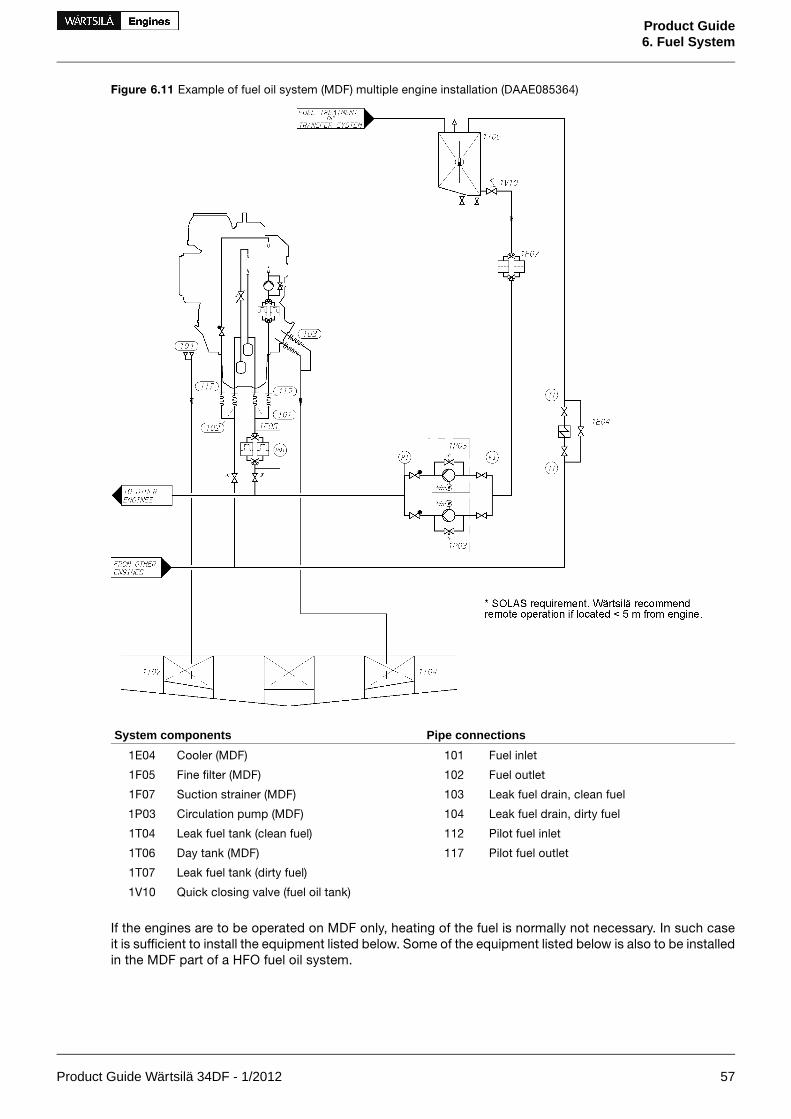
Figure 6.11 Example of fuel oil system (MDF) multiple engine installation (DAAE085364)
Pipe connectionsSystem components
Fuel inlet101Cooler (MDF)1E04
Fuel outlet102Fine filter (MDF)1F05
Leak fuel drain, clean fuel103Suction strainer (MDF)1F07
Leak fuel drain, dirty fuel104Circulation pump (MDF)1P03
Pilot fuel inlet112Leak fuel tank (clean fuel)1T04
Pilot fuel outlet117Day tank (MDF)1T06
Leak fuel tank (dirty fuel)1T07
Quick closing valve (fuel oil tank)1V10
If the engines are to be operated on MDF only, heating of the fuel is normally not necessary. In such caseit is sufficient to install the equipment listed below. Some of the equipment listed below is also to be installedin the MDF part of a HFO fuel oil system.
Product Guide Wärtsilä 34DF - 1/2012 57
Product Guide6. Fuel System

Circulation pump, MDF (1P03)
The circulation pump maintains the pressure at the injection pumps and circulates the fuel in the system.It is recommended to use a screw pump as circulation pump. A suction strainer with a fineness of 0.5 mmshould be installed before each pump. There must be a positive static pressure of about 30 kPa on thesuction side of the pump.
Design data:
5 x the total consumption of the connected enginesCapacity
1.6 MPa (16 bar)Design pressure
1.0 MPa (10 bar)Max. total pressure (safety valve)
see chapter "Technical Data"Nominal pressure
50°CDesign temperature
90 cStViscosity for dimensioning of electric motor
Flow meter, MDF (1I03)
If the return fuel from the engine is conducted to a return fuel tank instead of the day tank, one consumptionmeter is sufficient for monitoring of the fuel consumption, provided that the meter is installed in the feedline from the day tank (before the return fuel tank). A fuel oil cooler is usually required with a return fuel tank.
The total resistance of the flow meter and the suction strainer must be small enough to ensure a positivestatic pressure of about 30 kPa on the suction side of the circulation pump.
There should be a by-pass line around the consumption meter, which opens automatically in case of ex-cessive pressure drop.
Fine filter, MDF (1F05)
The fuel oil fine filter is a full flow duplex type filter with steel net. This filter must be installed as near theengine as possible.
The diameter of the pipe between the fine filter and the engine should be the same as the diameter beforethe filters.
Design data:
according to fuel specificationsFuel viscosity
50°CDesign temperature
Equal to feed/circulation pump capacityDesign flow
1.6 MPa (16 bar)Design pressure
37 μm (absolute mesh size)Fineness
Maximum permitted pressure drops at 14 cSt:
20 kPa (0.2 bar)- clean filter
80 kPa (0.8 bar)- alarm
MDF cooler (1E04)
The fuel viscosity may not drop below the minimum value stated in Technical data. When operating onMDF, the practical consequence is that the fuel oil inlet temperature must be kept below 45°C. Very lightfuel grades may require even lower temperature.
Sustained operation on MDF usually requires a fuel oil cooler. The cooler is to be installed in the return lineafter the engine(s). LT-water is normally used as cooling medium.
Design data:
2.5 kW/cylHeat to be dissipated
80 kPa (0.8 bar)Max. pressure drop, fuel oil
60 kPa (0.6 bar)Max. pressure drop, water
min. 15%Margin (heat rate, fouling)
58 Product Guide Wärtsilä 34DF - 1/2012
Product Guide6. Fuel System
Design data:
50/150°CDesign temperature MDF/HFO installation
Return fuel tank (1T13)
The return fuel tank shall be equipped with a vent valve needed for the vent pipe to the MDF day tank. Thevolume of the return fuel tank should be at least 100 l.
Black out start
Diesel generators serving as the main source of electrical power must be able to resume their operation ina black out situation by means of stored energy. Depending on system design and classification regulations,it may in some cases be permissible to use the emergency generator. HFO engines without engine drivenfuel feed pump can reach sufficient fuel pressure to enable black out start by means of:
• A gravity tank located min. 15 m above the crankshaft
• A pneumatically driven fuel feed pump (1P11)
• An electrically driven fuel feed pump (1P11) powered by an emergency power source
Product Guide Wärtsilä 34DF - 1/2012 59
Product Guide6. Fuel System

Fuel feed system - HFO installations
Figure 6.12 Example of fuel oil system (HFO), multiple engine installation (DAAE085365B)
System components:
Circulation pump (booster unit)1P06Heater (booster unit)1E02
Circulation pump (HFO, MDF)1P12Cooler (booster unit)1E03
Pilot fuel feed pump (MDF)1P13Cooler (MDF)1E04
Day tank (HFO)1T03Safety filter (HFO)1F03
Leak fuel tank (clean fuel)1T04Fine filter (MDF)1F05
Day tank (MDF)1T06Suction filter (booster unit)1F06
Leak fuel tank (dirty fuel)1T07Suction strainer (MDF)1F07
De-aeration tank (booster unit)1T08Automatic filter (booster unit)1F08
Changeover valve1V01Flow meter (booster unit)1I01
Pressure control valve (booster unit)1V03Viscosity meter (booster unit)1I02
Overflow valve (HFO/MDF)1V05Feeder / Booster unit1N01
Overflow valve (HFO/MDF)1V05-1Pump and filter unit (HFO/MDF)1N03
Venting valve (booster unit)1V07Fuel feed pump (booster unit)1P04
Pipe connections:
Leak fuel drain, dirty fuel104Fuel inlet101
Pilot fuel inlet112Fuel outlet102
Pilot fuel outlet117Leak fuel drain, clean fuel103
60 Product Guide Wärtsilä 34DF - 1/2012
Product Guide6. Fuel System

HFO pipes shall be properly insulated. If the viscosity of the fuel is 180 cSt/50°C or higher, the pipes mustbe equipped with trace heating. It shall be possible to shut off the heating of the pipes when operating onMDF (trace heating to be grouped logically).
Starting and stopping
In diesel mode operation, the engine can be started and stopped on HFO provided that the engine and thefuel system are pre-heated to operating temperature. The fuel must be continuously circulated also througha stopped engine in order to maintain the operating temperature. Changeover to MDF for start and stop isnot required.
Prior to overhaul or shutdown of the external system the engine fuel system shall be flushed and filled withMDF.
Changeover from HFO to MDF
The control sequence and the equipment for changing fuel during operation must ensure a smooth changein fuel temperature and viscosity. When MDF is fed through the HFO feeder/booster unit, the volume in thesystem is sufficient to ensure a reasonably smooth transfer.
When there are separate circulating pumps for MDF, then the fuel change should be performed with theHFO feeder/booster unit before switching over to the MDF circulating pumps. As mentioned earlier, sustainedoperation on MDF usually requires a fuel oil cooler. The viscosity at the engine shall not drop below theminimum limit stated in chapter Technical data.
Number of engines in the same system
When the fuel feed unit serves Wärtsilä 34DF engines only, maximum one engine should be connected tothe same fuel feed circuit, unless individual circulating pumps before each engine are installed.
Main engines and auxiliary engines should preferably have separate fuel feed units. Individual circulatingpumps or other special arrangements are often required to have main engines and auxiliary engines in thesame fuel feed circuit. Regardless of special arrangements it is not recommended to supply more thanmaximum two main engines and two auxiliary engines, or one main engine and three auxiliary engines fromthe same fuel feed unit.
In addition the following guidelines apply:
• Twin screw vessels with two engines should have a separate fuel feed circuit for each propeller shaft.
• Twin screw vessels with four engines should have the engines on the same shaft connected to differentfuel feed circuits. One engine from each shaft can be connected to the same circuit.
Feeder/booster unit (1N01)
A completely assembled feeder/booster unit can be supplied. This unit comprises the following equipment:
• Two suction strainers
• Two fuel feed pumps of screw type, equipped with built-on safety valves and electric motors
• One pressure control/overflow valve
• One pressurized de-aeration tank, equipped with a level switch operated vent valve
• Two circulating pumps, same type as the fuel feed pumps
• Two heaters, steam, electric or thermal oil (one heater in operation, the other as spare)
• One automatic back-flushing filter with by-pass filter
• One viscosimeter for control of the heaters
• One control valve for steam or thermal oil heaters, a control cabinet for electric heaters
• One thermostatic valve for emergency control of the heaters
• One control cabinet including starters for pumps
• One alarm panel
Product Guide Wärtsilä 34DF - 1/2012 61
Product Guide6. Fuel System

The above equipment is built on a steel frame, which can be welded or bolted to its foundation in the ship.The unit has all internal wiring and piping fully assembled. All HFO pipes are insulated and provided withtrace heating.
Figure 6.13 Feeder/booster unit, example (DAAE006659)
Fuel feed pump, booster unit (1P04)
The feed pump maintains the pressure in the fuel feed system. It is recommended to use a screw pump asfeed pump. The capacity of the feed pump must be sufficient to prevent pressure drop during flushing ofthe automatic filter.
A suction strainer with a fineness of 0.5 mm should be installed before each pump. There must be a positivestatic pressure of about 30 kPa on the suction side of the pump.
Design data:
Total consumption of the connected engines added with theflush quantity of the automatic filter (1F08)
Capacity
1.6 MPa (16 bar)Design pressure
0.7 MPa (7 bar)Max. total pressure (safety valve)
100°CDesign temperature
62 Product Guide Wärtsilä 34DF - 1/2012
Product Guide6. Fuel System

Design data:
1000 cStViscosity for dimensioning of electric motor
Pressure control valve, booster unit (1V03)
The pressure control valve in the feeder/booster unit maintains the pressure in the de-aeration tank by dir-ecting the surplus flow to the suction side of the feed pump.
Design data:
Equal to feed pumpCapacity
1.6 MPa (16 bar)Design pressure
100°CDesign temperature
0.3...0.5 MPa (3...5 bar)Set-point
Automatic filter, booster unit (1F08)
It is recommended to select an automatic filter with a manually cleaned filter in the bypass line. The auto-matic filter must be installed before the heater, between the feed pump and the de-aeration tank, and itshould be equipped with a heating jacket. Overheating (temperature exceeding 100°C) is however to beprevented, and it must be possible to switch off the heating for operation on MDF.
Design data:
According to fuel specificationFuel viscosity
100°CDesign temperature
If fuel viscosity is higher than 25 cSt/100°CPreheating
Equal to feed pump capacityDesign flow
1.6 MPa (16 bar)Design pressure
Fineness:
35 μm (absolute mesh size)- automatic filter
35 μm (absolute mesh size)- by-pass filter
Maximum permitted pressure drops at 14 cSt:
20 kPa (0.2 bar)- clean filter
80 kPa (0.8 bar)- alarm
Flow meter, booster unit (1I01)
If a fuel consumption meter is required, it should be fitted between the feed pumps and the de-aerationtank. When it is desired to monitor the fuel consumption of individual engines in a multiple engine installation,two flow meters per engine are to be installed: one in the feed line and one in the return line of each engine.
There should be a by-pass line around the consumption meter, which opens automatically in case of ex-cessive pressure drop.
If the consumption meter is provided with a prefilter, an alarm for high pressure difference across the filteris recommended.
De-aeration tank, booster unit (1T08)
It shall be equipped with a low level alarm switch and a vent valve. The vent pipe should, if possible, be leddownwards, e.g. to the overflow tank. The tank must be insulated and equipped with a heating coil. Thevolume of the tank should be at least 100 l.
Circulation pump, booster unit (1P06)
The purpose of this pump is to circulate the fuel in the system and to maintain the required pressure at theinjection pumps, which is stated in the chapter Technical data. By circulating the fuel in the system it alsomaintains correct viscosity, and keeps the piping and the injection pumps at operating temperature.
When more than one engine is connected to the same feeder/booster unit, individual circulation pumps(1P12) must be installed before each engine.
Product Guide Wärtsilä 34DF - 1/2012 63
Product Guide6. Fuel System

Design data:
Capacity:
5 x the total consumption of the connected engines- without circulation pumps (1P12)
15% more than total capacity of all circulation pumps- with circulation pumps (1P12)
1.6 MPa (16 bar)Design pressure
1.0 MPa (10 bar)Max. total pressure (safety valve)
150°CDesign temperature
500 cStViscosity for dimensioning of electric motor
Heater, booster unit (1E02)
The heater must be able to maintain a fuel viscosity of 14 cSt at maximum fuel consumption, with fuel ofthe specified grade and a given day tank temperature (required viscosity at injection pumps stated inTechnical data). When operating on high viscosity fuels, the fuel temperature at the engine inlet may notexceed 135°C however.
The power of the heater is to be controlled by a viscosimeter. The set-point of the viscosimeter shall besomewhat lower than the required viscosity at the injection pumps to compensate for heat losses in thepipes. A thermostat should be fitted as a backup to the viscosity control.
To avoid cracking of the fuel the surface temperature in the heater must not be too high. The heat transferrate in relation to the surface area must not exceed 1.5 W/cm2.
The required heater capacity can be estimated with the following formula:
where:
heater capacity (kW)P =
total fuel consumption at full output + 15% margin [l/h]Q =
temperature rise in heater [°C]ΔT =
Viscosimeter, booster unit (1I02)
The heater is to be controlled by a viscosimeter. The viscosimeter should be of a design that can withstandthe pressure peaks caused by the injection pumps of the diesel engine.
Design data:
0...50 cStOperating range
180°CDesign temperature
4 MPa (40 bar)Design pressure
Pump and filter unit (1N03)
When more than one engine is connected to the same feeder/booster unit, a circulation pump (1P12) mustbe installed before each engine. The circulation pump (1P12) and the safety filter (1F03) can be combinedin a pump and filter unit (1N03). A safety filter is always required.
There must be a by-pass line over the pump to permit circulation of fuel through the engine also in casethe pump is stopped. The diameter of the pipe between the filter and the engine should be the same sizeas between the feeder/booster unit and the pump and filter unit.
Circulation pump (1P12)
The purpose of the circulation pump is to ensure equal circulation through all engines. With a commoncirculation pump for several engines, the fuel flow will be divided according to the pressure distribution inthe system (which also tends to change over time) and the control valve on the engine has a very flatpressure versus flow curve.
64 Product Guide Wärtsilä 34DF - 1/2012
Product Guide6. Fuel System

In installations where MDF is fed directly from the MDF tank (1T06) to the circulation pump, a suctionstrainer (1F07) with a fineness of 0.5 mm shall be installed to protect the circulation pump. The suctionstrainer can be common for all circulation pumps.
Design data:
5 x the fuel consumption of the engineCapacity
1.6 MPa (16 bar)Design pressure
1.0 MPa (10 bar)Max. total pressure (safety valve)
150°CDesign temperature
Pressure for dimensioning of electric motor (ΔP):
0.7 MPa (7 bar)- if MDF is fed directly from day tank
0.3 MPa (3 bar)- if all fuel is fed through feeder/booster unit
500 cStViscosity for dimensioning of electric motor
Safety filter (1F03)
The safety filter is a full flow duplex type filter with steel net. The filter should be equipped with a heatingjacket. The safety filter or pump and filter unit shall be installed as close as possible to the engine.
Design data:
according to fuel specificationFuel viscosity
150°CDesign temperature
Equal to circulation pump capacityDesign flow
1.6 MPa (16 bar)Design pressure
37 μm (absolute mesh size)Filter fineness
Maximum permitted pressure drops at 14 cSt:
20 kPa (0.2 bar)- clean filter
80 kPa (0.8 bar)- alarm
Overflow valve, HFO (1V05)
When several engines are connected to the same feeder/booster unit an overflow valve is needed betweenthe feed line and the return line. The overflow valve limits the maximum pressure in the feed line, when thefuel lines to a parallel engine are closed for maintenance purposes.
The overflow valve should be dimensioned to secure a stable pressure over the whole operating range.
Design data:
Equal to circulation pump (1P06)Capacity
1.6 MPa (16 bar)Design pressure
150°CDesign temperature
0.2...0.7 MPa (2...7 bar)Set-point (Δp)
Pilot fuel feed pump, MDF (1P13)
The pilot fuel feed pump is needed in HFO installations. The pump feed the engine with MDF fuel to thepilot fuel system. No HFO is allowed to enter the pilot fuel system.
It is recommended to use a screw pump as circulation pump. A suction strainer with a fineness of 0.5 mmshould be installed before each pump. There must be a positive static pressure of about 30 kPa on thesuction side of the pump.
Design data:
1 m3/h per engineCapacity
1.6 MPa (16 bar)Design pressure
1.0 MPa (10 bar)Max. total pressure (safety valve)
Product Guide Wärtsilä 34DF - 1/2012 65
Product Guide6. Fuel System

Design data:
see chapter "Technical Data"Nominal pressure
50°CDesign temperature
90 cStViscosity for dimensioning of electric motor
Flushing
The external piping system must be thoroughly flushed before the engines are connected and fuel is circulatedthrough the engines. The piping system must have provisions for installation of a temporary flushing filter.
The fuel pipes at the engine (connections 101 and 102) are disconnected and the supply and return linesare connected with a temporary pipe or hose on the installation side. All filter inserts are removed, exceptin the flushing filter of course. The automatic filter and the viscosimeter should be bypassed to preventdamage. The fineness of the flushing filter should be 35 μm or finer.
66 Product Guide Wärtsilä 34DF - 1/2012
Product Guide6. Fuel System

7. Lubricating Oil System
7.1 Lubricating oil requirements
7.1.1 Engine lubricating oilThe lubricating oil must be of viscosity class SAE 40 and have a viscosity index (VI) of minimum 95. Thelubricating oil alkalinity (BN) is tied to the fuel grade, as shown in the table below. BN is an abbreviation ofBase Number. The value indicates milligrams KOH per gram of oil.
Table 7.1 Fuel standards and lubricating oil requirements, gas and MDF operation
Lubricating oil BNFuel standardCategory
10...20GRADE 1-D, 2-DDMX, DMADA, DXISO-F-DMX, DMA
ASTM D 975-01,BS MA 100: 1996CIMAC 2003ISO 8217: 2005(E)
A
15...20DMBDBISO-F-DMB
BS MA 100: 1996CIMAC 2003ISO 8217: 2005(E)
B
If gas oil or MDF is continuously used as fuel, lubricating oil with a BN of 10-20 is recommended to beused. In periodic operation with natural gas and MDF, lubricating oil with a BN of 10-15 is recommended.
The required lubricating oil alkalinity in HFO operation is tied to the fuel specified for the engine, which isshown in the following table.
Table 7.2 Fuel standards and lubricating oil requirements, HFO operation
Lubricating oil BNFuel standardCategory
30...55
GRADE NO. 4DGRADE NO. 5-6DMC, RMA10-RMK55DC, A30-K700ISO-F-DMC, RMA30-RMK700
ASTM D 975-01ASTM D 396-04,BS MA 100: 1996CIMAC 2003,ISO 8217: 2005 (E)
C
In installation where engines are running periodically with different fuel qualities, i.e. natural gas, MDF andHFO, lubricating oil quality must be chosen based on HFO requirements. BN 50-55 lubricants are to beselected in the first place for operation on HFO. BN 40 lubricants can also be used with HFO provided thatthe sulphur content of the fuel is relatively low, and the BN remains above the condemning limit for acceptableoil change intervals. BN 30 lubricating oils should be used together with HFO only in special cases; for ex-ample in SCR (Selective Catalyctic Reduction) installations, if better total economy can be achieved despiteshorter oil change intervals. Lower BN may have a positive influence on the lifetime of the SCR catalyst.
It is not harmful to the engine to use a higher BN than recommended for the fuel grade.
Different oil brands may not be blended, unless it is approved by the oil suppliers. Blending of different oilsmust also be approved by Wärtsilä, if the engine still under warranty.
An updated list of approved lubricating oils is supplied for every installation.
7.1.2 Oil in speed governor or actuatorAn oil of viscosity class SAE 30 or SAE 40 is acceptable in normal operating conditions. Usually the sameoil as in the engine can be used. At low ambient temperatures it may be necessary to use a multigrade oil(e.g. SAE 5W-40) to ensure proper operation during start-up with cold oil.
7.1.3 Oil in turning deviceIt is recommended to use EP-gear oils, viscosity 400-500 cSt at 40°C = ISO VG 460.
An updated list of approved oils is supplied for every installation.
Product Guide Wärtsilä 34DF - 1/2012 67
Product Guide7. Lubricating Oil System

7.1.4 Pilot fuel pumpIt is recommended to use lithium soap based EP-greases having a penetration of 300...350 when measuredaccording to ASTM D 217 standard and being classed as NLGI Grade 1 at 30...70°C operating temperature.
An updated list of approved oils is supplied for every installation.
7.2 Internal lubricating oil systemFigure 7.1 Internal lubricating oil system, in-line engines (DAAE055611a)
System components:
Centrifugal filter06Lubricating oil main pump01
Pressure control valve07Prelubricating oil pump02
Turbocharger08Lubricating oil cooler03
Camshaft bearings and cylinder head lubrication09Thermostatic valve04
Automatic filter05
Sensors and indicators:
Lubricating oil pressure, TC inletPT271Lubricating oil pressure, engine inletPT201
Lubricating oil temperature, TC outletTE272Lubricating oil pressure, engine inletPTZ201
Oil mist detectorQU700Lubricating oil temperature, engine inletTE201
Lubricating oil temperature, engine inlet (if ME)TI201Lubricating oil low level (wet sump)LS204
Main bearing temperatureTE7##Lub. oil stand-by pump start (if stand-by pump)PS210
Lubricating oil filter pressure differencePDT243
StandardPressure classSizePipe connections
ISO 7005-1PN16DN150Lubricating oil outlet (dry sump)202
ISO 7005-1PN16DN200Lubricating oil to engine driven pump (dry sump)203
ISO 7005-1PN16DN80Lubricating oil to priming pump (dry sump)205
ISO 7005-1PN16DN150Lubricating oil to el.driven pump (stand-by pump)207
ISO 7005-1PN16DN100Lubricating oil from el.driven pump (stand-by pump)208
ISO 7005-1PN40DN40Lubricating oil from separator and filling (wet sump)213
ISO 7005-1PN40DN40Lubricating oil to separator and drain (wet sump)214
68 Product Guide Wärtsilä 34DF - 1/2012
Product Guide7. Lubricating Oil System

StandardPressure classSizePipe connections
ISO 7005-1PN40DN40Lubricating oil filling (wet sump)215
M22 x 1.5Lubricating oil drain (wet sump)216
ISO 7005-1PN16DN80Crankcase air vent701
Figure 7.2 Internal lubricating oil system, V-engines (DAAE080919)
System components
Centrifugal filter06Lubricating oil main pump01
Pressure control valve07Prelubricating oil pump02
Turbocharger08Lubricating oil cooler03
Camshaft bearings and cylinder head lubrication09Thermostatic valve04
Automatic filter05
Sensors and indicators
Lubricating oil temperature, TC A outletTE272Lubricating oil pressure, engine inletPT201
Lubricating oil pressure, TC B inletPT281Lubricating oil pressure, engine inletPTZ201
Lubricating oil temperature, TC B outletTE282Lubricating oil temperature, engine inletTE201
Oil mist detectorQU700Lubricating oil low level (wet sump)LS204
Main bearing temperatureTE7##Lub. oil stand-by pump start (if stand-by pump)PS210
Lubricating oil temperature, engine inlet (if ME)TI201Lubricating oil filter pressure differencePDT243
Lubricating oil pressure, TC A inletPT271
StandardPressure classSizePipe connections
ISO 7005-1PN16DN150Lubricating oil outlet (dry sump)202
ISO 7005-1PN16DN200Lubricating oil to engine driven pump (dry sump)203
ISO 7005-1PN16DN125Lubricating oil to priming pump (dry sump)205
ISO 7005-1PN16DN200Lubricating oil to el.driven pump207
ISO 7005-1PN16DN125Lubricating oil from el.driven pump208
Product Guide Wärtsilä 34DF - 1/2012 69
Product Guide7. Lubricating Oil System

StandardPressure classSizePipe connections
ISO 7005-1PN40DN40Lubricating oil from separator and filling (wet sump)213
ISO 7005-1PN40DN40Lubricating oil to separator and drain (wet sump)214
ISO 7005-1PN40DN40Lubricating oil filling (wet sump)215
M22 x 1.5Lubricating oil drain (wet sump)216
ISO 7005-1PN16DN100Crankcase air vent701
The lubricating oil sump is of wet sump type. Dry sump is an option for main engines.
The direct driven lubricating oil pump is of gear type and equipped with a pressure control valve. The pumpis dimensioned to provide sufficient flow even at low speeds. A stand-by pump connection is available asoption. Concerning flow rate and pressure of the engine driven pump, see Technical data.
The pre-lubricating oil pump is an electric motor driven gear pump equipped with a safety valve. The pumpshould always be running, when the engine is stopped. Concerning flow rate and pressure of the pre-lub-ricating oil pump, see Technical data.
The lubricating oil module built on the engine consists of the lubricating oil cooler, thermostatic valve andautomatic filter.
The centrifugal filter is installed to clean the back-flushing oil from the automatic filter.
All dry sump engines are delivered with a running-in filter before each main bearing. These filters are to beremoved after commissioning.
70 Product Guide Wärtsilä 34DF - 1/2012
Product Guide7. Lubricating Oil System

7.3 External lubricating oil systemFigure 7.3 Example of lubricating oil system, wet oil sump (DAAE055757a)
Pipe connectionsSystem components
Lubricating oil to el.driven pump207Heater (separator unit)2E02
Lubricating oil from el. driven pump208Suction filter (separator unit)2F03
Lubricating oil from separator and filling213Suction strainer (stand-by pump)2F06
Lubricating oil to separator and drain214Separator unit2N01
Lubricating oil filling215Separator pump (separator unit)2P03
Lubricating oil drain216Stand-by pump2P04
Crankcase air vent701Separator2S01
Condensate trap2S02
New oil tank2T03
Renovating oil tank2T04
Renovated oil tank2T05
Sludge tank2T06
Product Guide Wärtsilä 34DF - 1/2012 71
Product Guide7. Lubricating Oil System

Figure 7.4 Example of lubricating oil system, dry oil sump (DAAE055758a)
Pipe connectionsSystem components
Lube oil outlet202Heater (separator unit)2E02
Lube oil to engine driven pump203Suction strainer (main lube oil pump)2F01
Lube oil to priming pump205Suction filter (separator unit)2F03
Lube oil from el.driven pump208Suction strainer (prelubricating oil pump)2F04
Crankcase air vent701Suction strainer (stand-by pump)2F06
Separator unit2N01
Separator pump (separator unit)2P03
Stand-by pump2P04
Separator2S01
Condensate trap2S02
System oil tank2T01
Sludge tank2T06
7.3.1 Separation system
Separator unit (2N01)
Each main engine must have a dedicated lubricating oil separator and the separators shall be dimensionedfor continuous separating. If the installation is designed to operate on gas/MDF only, then intermittentseparating might be sufficient.
72 Product Guide Wärtsilä 34DF - 1/2012
Product Guide7. Lubricating Oil System

Auxiliary engines operating on HFO having a viscosity of max. 380 cSt / 50°C may have a common lubric-ating oil separator unit. Two engines may have a common lubricating oil separator unit. In installations withfour or more engines two lubricating oil separator units should be installed.
Separators are usually supplied as pre-assembled units.
Typically lubricating oil separator units are equipped with:
• Feed pump with suction strainer and safety valve
• Preheater
• Separator
• Control cabinet
The lubricating oil separator unit may also be equipped with an intermediate sludge tank and a sludgepump, which offers flexibility in placement of the separator since it is not necessary to have a sludge tankdirectly beneath the separator.
Separator feed pump (2P03)
The feed pump must be selected to match the recommended throughput of the separator. Normally thepump is supplied and matched to the separator by the separator manufacturer.
The lowest foreseen temperature in the system oil tank (after a long stop) must be taken into account whendimensioning the electric motor.
Separator preheater (2E02)
The preheater is to be dimensioned according to the feed pump capacity and the temperature in the systemoil tank. When the engine is running, the temperature in the system oil tank located in the ship's bottom isnormally 65...75°C. To enable separation with a stopped engine the heater capacity must be sufficient tomaintain the required temperature without heat supply from the engine.
Recommended oil temperature after the heater is 95°C.
The surface temperature of the heater must not exceed 150°C in order to avoid cooking of the oil.
The heaters should be provided with safety valves and drain pipes to a leakage tank (so that possibleleakage can be detected).
Separator (2S01)
The separators should preferably be of a type with controlled discharge of the bowl to minimize the lubric-ating oil losses.
The service throughput Q [l/h] of the separator can be estimated with the formula:
where:
volume flow [l/h]Q =
engine output [kW]P =
number of through-flows of tank volume per day: 5 for HFO, 4 for MDFn =
operating time [h/day]: 24 for continuous separator operation, 23 for normal dimensioningt =
Sludge tank (2T06)
The sludge tank should be located directly beneath the separators, or as close as possible below the sep-arators, unless it is integrated in the separator unit. The sludge pipe must be continuously falling.
Renovating oil tank (2T04)
In case of wet sump engines the oil sump content can be drained to this tank prior to separation.
Product Guide Wärtsilä 34DF - 1/2012 73
Product Guide7. Lubricating Oil System

Renovated oil tank (2T05)
This tank contains renovated oil ready to be used as a replacement of the oil drained for separation.
7.3.2 System oil tank (2T01)Recommended oil tank volume is stated in chapter Technical data.
The system oil tank is usually located beneath the engine foundation. The tank may not protrude under thereduction gear or generator, and it must also be symmetrical in transverse direction under the engine. Thelocation must further be such that the lubricating oil is not cooled down below normal operating temperature.Suction height is especially important with engine driven lubricating oil pump. Losses in strainers etc. addto the geometric suction height. Maximum suction ability of the pump is stated in chapter Technical data.
The pipe connection between the engine oil sump and the system oil tank must be flexible to preventdamages due to thermal expansion. The return pipes from the engine oil sump must end beneath the min-imum oil level in the tank. Further on the return pipes must not be located in the same corner of the tankas the suction pipe of the pump.
The suction pipe of the pump should have a trumpet shaped or conical inlet to minimise the pressure loss.For the same reason the suction pipe shall be as short and straight as possible and have a sufficient dia-meter. A pressure gauge shall be installed close to the inlet of the lubricating oil pump. The suction pipeshall further be equipped with a non-return valve of flap type without spring. The non-return valve is partic-ularly important with engine driven pump and it must be installed in such a position that self-closing is en-sured.
Suction and return pipes of the separator must not be located close to each other in the tank.
The ventilation pipe from the system oil tank may not be combined with crankcase ventilation pipes.
It must be possible to raise the oil temperature in the tank after a long stop. In cold conditions it can benecessary to have heating coils in the oil tank in order to ensure pumpability. The separator heater cannormally be used to raise the oil temperature once the oil is pumpable. Further heat can be transferred tothe oil from the preheated engine, provided that the oil viscosity and thus the power consumption of thepre-lubricating oil pump does not exceed the capacity of the electric motor.
Fuel gas in the crankcase is soluble in very small portions into lubricating oil. Therefore, it is possible thatsmall amounts of fuel gas may be carried with lubricating oil into the DF-engine system oil tank and evap-orate there in the free space above the oil level. Therefore, the system oil tank has to be of the closed-toptype. The DF-engine system oil tank has to be treated similarly to the gas pipe ventilation or crankcaseventilation. Openings into open air from the system oil tank other than the breather pipe have to be eitherclosed or of a type that does not allow fuel gas to exit the tank (e.g. overflow pipe arrangement with waterlock). The system oil tank breathing pipes of engines located in the same engine room must not be combined.
The structure and the arrangement of the system oil tank may need to be approved by a ClassificationSociety project-specifically. Any instrumentation installed in the system oil tank has to be certified Ex ap-paratus.
74 Product Guide Wärtsilä 34DF - 1/2012
Product Guide7. Lubricating Oil System

Figure 7.5 Example of system oil tank arrangement (DAAE007020e)
Design data:
1.2...1.5 l/kW, see also Technical dataOil tank volume
75...80% of tank volumeOil level at service
60% of tank volumeOil level alarm
7.3.3 New oil tank (2T03)In engines with wet sump, the lubricating oil may be filled into the engine, using a hose or an oil can, throughthe crankcase cover or through the separator pipe. The system should be arranged so that it is possibleto measure the filled oil volume.
7.3.4 Suction strainers (2F01, 2F04, 2F06)It is recommended to install a suction strainer before each pump to protect the pump from damage. Thesuction strainer and the suction pipe must be amply dimensioned to minimize pressure losses. The suctionstrainer should always be provided with alarm for high differential pressure.
Design data:
0.5...1.0 mmFineness
Product Guide Wärtsilä 34DF - 1/2012 75
Product Guide7. Lubricating Oil System

7.3.5 Lubricating oil pump, stand-by (2P04)The stand-by lubricating oil pump is normally of screw type and should be provided with an overflow valve.
Design data:
see Technical dataCapacity
0.8 MPa (8 bar)Design pressure, max
100°CDesign temperature, max.
SAE 40Lubricating oil viscosity
500 mm2/s (cSt)Viscosity for dimensioning the electric motor
7.4 Crankcase ventilation systemThe purpose of the crankcase ventilation is to evacuate gases from the crankcase in order to keep thepressure in the crankcase within acceptable limits.
Each engine must have its own vent pipe into open air. The crankcase ventilation pipes may not be combinedwith other ventilation pipes, e.g. vent pipes from the system oil tank.
The diameter of the pipe shall be large enough to avoid excessive back pressure. Other possible equipmentin the piping must also be designed and dimensioned to avoid excessive flow resistance.
A condensate trap must be fitted on the vent pipe near the engine.
The connection between engine and pipe is to be flexible.
Design data:
see Technical dataFlow
see Technical dataBackpressure, max.
80°CTemperature
Figure 7.6 Condensate trap (DAAE032780)
Minimum size of the ventilation pipe after the condensatetrap is:
W L34DF: DN100W V34DF: DN125
The max. back-pressure must also be considered when selectingthe ventilation pipe size.
76 Product Guide Wärtsilä 34DF - 1/2012
Product Guide7. Lubricating Oil System

7.5 Flushing instructionsFlushing instructions in this Product Guide are for guidance only. For contracted projects, read the specificinstructions included in the installation planning instructions (IPI).
7.5.1 Piping and equipment built on the engineFlushing of the piping and equipment built on the engine is not required and flushing oil shall not be pumpedthrough the engine oil system (which is flushed and clean from the factory). It is however acceptable tocirculate the flushing oil via the engine sump if this is advantageous. Cleanliness of the oil sump shall beverified after completed flushing.
7.5.2 External oil systemRefer to the system diagram(s) in section External lubricating oil system for location/description of thecomponents mentioned below.
If the engine is equipped with a wet oil sump the external oil tanks, new oil tank (2T03), renovating oil tank(2T04) and renovated oil tank (2T05) shall be verified to be clean before bunkering oil. Especially pipesleading from the separator unit (2N01) directly to the engine shall be ensured to be clean for instance bydisconnecting from engine and blowing with compressed air.
If the engine is equipped with a dry oil sump the external oil tanks, new oil tank and the system oil tank(2T01) shall be verified to be clean before bunkering oil.
Operate the separator unit continuously during the flushing (not less than 24 hours). Leave the separatorrunning also after the flushing procedure, this to ensure that any remaining contaminants are removed.
If an electric motor driven stand-by pump (2P04) is installed the pipe shall be flushed running the pumpcirculating engine oil through a temporary external oil filter (recommended mesh 34 microns) into the engineoil sump through a hose and a crankcase door. The pump shall be protected by a suction strainer (2F06).
Whenever possible the separator unit shall be in operation during the flushing to remove dirt. The separatorunit is to be left running also after the flushing procedure, this to ensure that any remaining contaminantsare removed.
7.5.3 Type of flushing oil
Viscosity
In order for the flushing oil to be able to remove dirt and transport it with the flow, ideal viscosity is 10...50cSt. The correct viscosity can be achieved by heating engine oil to about 65°C or by using a separateflushing oil which has an ideal viscosity in ambient temperature.
Flushing with engine oil
The ideal is to use engine oil for flushing. This requires however that the separator unit is in operation toheat the oil. Engine oil used for flushing can be reused as engine oil provided that no debris or other con-tamination is present in the oil at the end of flushing.
Flushing with low viscosity flushing oil
If no separator heating is available during the flushing procedure it is possible to use a low viscosity flushingoil instead of engine oil. In such a case the low viscosity flushing oil must be disposed of after completedflushing. Great care must be taken to drain all flushing oil from pockets and bottom of tanks so that flushingoil remaining in the system will not compromise the viscosity of the actual engine oil.
Lubricating oil sample
To verify the cleanliness a LO sample shall be taken by the shipyard after the flushing is completed. Theproperties to be analyzed are Viscosity, BN, AN, Insolubles, Fe and Particle Count.
Commissioning procedures shall in the meantime be continued without interruption unless the commissioningengineer believes the oil is contaminated.
Product Guide Wärtsilä 34DF - 1/2012 77
Product Guide7. Lubricating Oil System

8. Compressed Air SystemCompressed air is used to start engines and to provide actuating energy for safety and control devices.The use of starting air for other purposes is limited by the classification regulations.
To ensure the functionality of the components in the compressed air system, the compressed air has tobe free from solid particles and oil.
8.1 Instrument air qualityThe quality of instrument air, from the ships instrument air system, for safety and control devices must fulfillthe following requirements.
Instrument air specification:
1 MPa (10 bar)Design pressure
0.7 MPa (7 bar)Nominal pressure
+3°CDew point temperature
1 mg/m3Max. oil content
3 µmMax. particle size
8.2 Internal compressed air systemAll engines, independent of cylinder number, are started by means of compressed air with a nominal pressureof 3 MPa (30 bar). The start is performed by direct injection of air into the cylinders through the starting airvalves in the cylinder heads. The master starting valve, built on the engine, can be operated both manuallyand electrically.
The starting air system is equipped with a slow turning valve, which rotates the engine slowly without fuelinjection for a few turns before start. Slow turning is not performed if the engine has been running max. 30minutes earlier, or if slow turning is automatically performed every 30 minutes.
All engines have built-on non-return valves and flame arrestors. The engine can not be started when theturning gear is engaged.
78 Product Guide Wärtsilä 34DF - 1/2012
Product Guide8. Compressed Air System

Figure 8.1 Internal compressed air system, in-line engines (DAAE055612a)
System components
Flame arrestor09Main starting air valve01
Safety valve10Starting air distributor02
Drain valve11Starting air valve in cylinder head03
Start solenoid valve12Blocking valve, when turning gear engaged04
Stop solenoid valve13Air container05
Stop solenoid valve14Pneumatic stop cylinder at each injection pump06
Wastegate valve15Non-return valve07
Starting booster for speed governor08
Sensors and indicators
Start solenoid valveCV321Stop/shutdown solenoid valveCV153-1
Slow turning solenoid valveCV331Stop/shutdown solenoid valve 2CV153-2
Exhaust wastegate controlCV519Starting air pressure, engine inletPT301
MCC, degasing valve controlCV947Control air pressurePT311
Instrument air pressurePT312
StandardPressure classSizePipe connections
ISO 7005-1PN40DN32Starting air inlet, 3 MPa301
DIN2353OD12Control air to bypass/wastegate valve311
Product Guide Wärtsilä 34DF - 1/2012 79
Product Guide8. Compressed Air System

Figure 8.2 Internal compressed air system, V-engines (DAAE080920)
System components
Flame arrestor09Main starting air valve01
Safety valve10Starting air distributor02
Drain valve11Starting air valve in cylinder head03
Start solenoid valve12Blocking valve, when turning gear engaged04
Stop solenoid valve13Air container05
Stop solenoid valve14Pneumatic stop cylinder at each injection pump06
Wastegate valve15Non-return valve07
Starting booster for speed governor08
Sensors and indicators
Start solenoid valveCV321Stop/shutdown solenoid valveCV153-1
Slow turning solenoid valveCV331Stop/shutdown solenoid valve 2CV153-2
Exhaust wastegate controlCV519Starting air pressure, engine inletPT301
MCC, degasing valve controlCV947Control air pressurePT311
Instrument air pressurePT312
StandardPressure classSizePipe connections
ISO 7005-1PN40DN32Starting air inlet, 3 MPa301
DIN2353OD12Control air to bypass/wastegate valve311
80 Product Guide Wärtsilä 34DF - 1/2012
Product Guide8. Compressed Air System

8.3 External compressed air systemThe design of the starting air system is partly determined by classification regulations. Most classificationsocieties require that the total capacity is divided into two equally sized starting air receivers and startingair compressors. The requirements concerning multiple engine installations can be subject to special con-sideration by the classification society.
The starting air pipes should always be slightly inclined and equipped with manual or automatic drainingat the lowest points.
Instrument air to safety and control devices must be treated in an air dryer.
Figure 8.3 Example of external compressed air system (DAAE055759a)
Pipe connectionsSystem components
Starting air inlet, 3 MPa301Air filter (starting air inlet)3F02
Control air to bypass/wastegate valve311Starting air compressor unit3N02
Air dryer unit3N06
Compressor (Starting air compressor unit)3P01
Separator (Starting air compressor unit)3S01
Starting air vessel3T01
8.3.1 Starting air compressor unit (3N02)At least two starting air compressors must be installed. It is recommended that the compressors are capableof filling the starting air vessel from minimum (1.8 MPa) to maximum pressure in 15...30 minutes. For exactdetermination of the minimum capacity, the rules of the classification societies must be followed.
Product Guide Wärtsilä 34DF - 1/2012 81
Product Guide8. Compressed Air System

8.3.2 Oil and water separator (3S01)An oil and water separator should always be installed in the pipe between the compressor and the air vessel.Depending on the operation conditions of the installation, an oil and water separator may be needed in thepipe between the air vessel and the engine.
8.3.3 Starting air vessel (3T01)The starting air vessels should be dimensioned for a nominal pressure of 3 MPa.
The number and the capacity of the air vessels for propulsion engines depend on the requirements of theclassification societies and the type of installation.
It is recommended to use a minimum air pressure of 1.8 MPa, when calculating the required volume of thevessels.
The starting air vessels are to be equipped with at least a manual valve for condensate drain. If the airvessels are mounted horizontally, there must be an inclination of 3...5° towards the drain valve to ensureefficient draining.
Figure 8.4 Starting air vessel
Weight[kg]
Dimensions [mm]Size[Litres] DL3 1)L2 1)L1
2744801102431767250
4504801332433204500
6256501332552740710
81065013325535601000
1) Dimensions are approximate.
The starting air consumption stated in technical data is for a successful start. During a remote start themain starting valve is kept open until the engine starts, or until the max. time for the starting attempt haselapsed. A failed remote start can consume two times the air volume stated in technical data. If the shiphas a class notation for unattended machinery spaces, then the starts are to be demonstrated as remotestarts, usually so that only the last starting attempt is successful.
The required total starting air vessel volume can be calculated using the formula:
where:
total starting air vessel volume [m3]VR =
normal barometric pressure (NTP condition) = 0.1 MPapE =
air consumption per start [Nm3] See Technical dataVE =
82 Product Guide Wärtsilä 34DF - 1/2012
Product Guide8. Compressed Air System

where:
required number of starts according to the classification societyn =
maximum starting air pressure = 3 MPapRmax =
minimum starting air pressure = 1.8 MPapRmin =
NOTE! The total vessel volume shall be divided into at least two equally sized starting air vessels.
8.3.4 Starting air filter (3F02)Condense formation after the water separator (between starting air compressor and starting air vessels)create and loosen abrasive rust from the piping, fittings and receivers. Therefore it is recommended to installa filter before the starting air inlet on the engine to prevent particles to enter the starting air equipment.
An Y-type strainer can be used with a stainless steel screen and mesh size 400 µm. The pressure dropshould not exceed 20 kPa (0.2 bar) for the engine specific starting air consumption under a time span of 4seconds.
Product Guide Wärtsilä 34DF - 1/2012 83
Product Guide8. Compressed Air System

9. Cooling Water System
9.1 Water qualityThe fresh water in the cooling water system of the engine must fulfil the following requirements:
min. 6.5pH ...............................
max. 10 °dHHardness ....................
max. 80 mg/lChlorides ....................
max. 150 mg/lSulphates ....................
Good quality tap water can be used, but shore water is not always suitable. It is recommended to use waterproduced by an onboard evaporator. Fresh water produced by reverse osmosis plants often has higherchloride content than permitted. Rain water is unsuitable as cooling water due to the high content of oxygenand carbon dioxide.
Only treated fresh water containing approved corrosion inhibitors may be circulated through the engines.It is important that water of acceptable quality and approved corrosion inhibitors are used directly whenthe system is filled after completed installation.
9.1.1 Corrosion inhibitorsThe use of an approved cooling water additive is mandatory. An updated list of approved products is suppliedfor every installation and it can also be found in the Instruction manual of the engine, together with dosageand further instructions.
9.1.2 GlycolUse of glycol in the cooling water is not recommended unless it is absolutely necessary. Glycol raises thecharge air temperature, which may require de-rating of the engine depending on gas properties and glycolcontent. Max. 50% glycol is permitted.
Corrosion inhibitors shall be used regardless of glycol in the cooling water.
84 Product Guide Wärtsilä 34DF - 1/2012
Product Guide9. Cooling Water System

9.2 Internal cooling water systemFigure 9.1 Internal cooling water system, in-line engines (DAAE055613a)
System components:
HT-thermostatic valve05HT-cooling water pump01
Charge air cooler (HT)06LT-cooling water pump02
Connection piece07Charge air cooler (LT)03
Lubricating oil cooler04
Sensors and indicators:
HT-water temperature after CACTE432HT-water pressure before cylinder jacketsPT401
LT-water pressure before CACPT471HT-water temperature before cylinder jacketsTE401
LT-water temperature before CACTE471HT-water temperature after cylinder jacketsTE402
LT-water temperature after CACTE482HT-water temperature after cylinder jacketsTEZ402
LT-water stand-by pump start (if stand-by pump)PS460HT-water stand-by pump start (if stand-by pump)PS410
StandardPressure classSizePipe connections
ISO 7005-1PN16DN100HT-water inlet401
ISO 7005-1PN16DN100HT-water outlet402
DIN 2353OD12HT-water air vent404
DIN 2353OD28Water from preheater to HT-circuit406
ISO 7005-1PN16DN100HT-water from stand-by pump408
ISO 7005-1PN16DN100LT-water inlet451
ISO 7005-1PN16DN100LT-water outlet452
DIN 2353OD15LT-water air vent from air cooler454
ISO 7005-1PN16DN100LT-water from stand-by pump457
Product Guide Wärtsilä 34DF - 1/2012 85
Product Guide9. Cooling Water System

Figure 9.2 Internal cooling water system, V-engines (DAAE080921)
System components:
HT-thermostatic valve05HT-cooling water pump01
Shut-off valve06LT-cooling water pump02
Charge air cooler (HT)07Charge air cooler (LT)03
Lubricating oil cooler04
Sensors and indicators:
HT-water temp. after cylinder jackets, A-bankTEZ402HT-water stand-by pump start (if stand-by pump)PS410
HT-water temp. after cylinder jackets, B-bankTEZ403HT-water pressure before cylinder jacketsPT401
LT-water stand-by pump start (if stand-by pump)PS460HT-water temperature before cylinder jacketsTE401
LT-water pressure before CACPT471HT-water temp. after cylinder jackets, A-bankTE402
LT-water temperature before CACTE471HT-water temp. after cylinder jackets, B-bankTE403
LT-water temperature after CACTE482HT-water temperature after CACTE432
StandardPressure classSizePipe connections
ISO 7005-1PN16DN125HT-water inlet401
ISO 7005-1PN16DN125HT-water outlet402
DIN 2353OD12HT-water air vent404
ISO 7005-1PN40DN32Water from preheater to HT-circuit406
ISO 7005-1PN16DN125HT-water from stand-by pump408
ISO 7005-1PN16DN125LT-water inlet451
ISO 7005-1PN16DN125LT-water outlet452
DIN 2353OD12LT-water air vent454
ISO 7005-1PN16DN125LT-water from stand-by pump457
86 Product Guide Wärtsilä 34DF - 1/2012
Product Guide9. Cooling Water System

The fresh water cooling system is divided into a high temperature (HT) and a low temperature (LT) circuit.The HT water circulates through cylinder jackets, cylinder heads and the 1st stage of the charge air cooler,if the engine is equipped with a two-stage charge air cooler. V-engines are equipped with a two-stagecharge air cooler, while in-line engines have a single-stage charge air cooler.
A two-stage charge air cooler enables more efficient heat recovery and heating of cold combustion air.
The LT water circulates through the charge air cooler and the lubricating oil cooler, which is built on theengine.
Temperature control valves regulate the temperature of the water out from the engine, by circulating somewater back to the cooling water pump inlet. The HT temperature control valve is always mounted on theengine, while the LT temperature control valve can be either on the engine or separate. In installations wherethe engines operate on MDF only it is possible to install the LT temperature control valve in the externalsystem and thus control the LT water temperature before the engine.
9.2.1 Engine driven circulating pumpsThe LT and HT cooling water pumps are engine driven. The engine driven pumps are located at the freeend of the engine.
Pump curves for engine driven pumps are shown in the diagrams. The nominal pressure and capacity canbe found in the chapter Technical data.
Figure 9.3 Pump curves for engine driven HT- and LT- water pumps
Product Guide Wärtsilä 34DF - 1/2012 87
Product Guide9. Cooling Water System

9.3 External cooling water systemFigure 9.4 External cooling water system, in-line engines (DAAE055760a)
System components:
Transfer pump4P09Cooler (MDF)1E04
Circulating pump (sea water)4P11Heater (preheater)4E05
Circulating pump (LT)4P15Central cooler4E08
Air venting4S01Cooler (reduction gear)4E10
Drain tank4T04Suction strainer (sea water)4F01
Expansion tank4T05Preheating unit4N01
Temperature control valve (heat recovery)4V02Evaporator unit4N02
Temperature control valve (central cooler)4V08Stand-by pump (HT)4P03
Temperature control valve (charge air)4V09Circulating pump (preheater)4P04
Stand-by pump (LT)4P05
Pipe connections:
LT-water inlet451HT-water inlet401
LT-water outlet452HT-water outlet402
LT-water air vent from air cooler454HT-water air vent404
LT-water from stand-by pump457Water from preheater to HT-circuit406
HT-water from stand-by pump408
88 Product Guide Wärtsilä 34DF - 1/2012
Product Guide9. Cooling Water System

Figure 9.5 External cooling water system, V-engines (DAAE084914)
System components:
Air venting4S01Heater (preheater)4E05
Drain tank4T04Central cooler4E08
Expansion tank4T05Preheating unit4N01
Temperature control valve (heat recovery)4V02Evaporator unit4N02
Temperature control valve (charge air)4V09Circulating pump (preheater)4P04
Transfer pump4P09
Pipe connections:
LT-water inlet451HT-water inlet401
LT-water outlet452HT-water outlet402
LT-water air vent from air cooler454HT-water air vent404
Water from preheater to HT-circuit406
Product Guide Wärtsilä 34DF - 1/2012 89
Product Guide9. Cooling Water System

Figure 9.6 External cooling water system, V-engines (DAAE089099)
System components:
Circulating pump (LT)4P15Cooler (MDF)1E04
Air venting4S01Heater (preheater)4E05
Drain tank4T04Central cooler4E08
Expansion tank4T05Cooler (reduction gear)4E10
Temperature control valve (heat recovery)4V02Preheating unit4N01
Temperature control valve (central cooler)4V08Evaporator unit4N02
Temperature control valve (charge air)4V09Circulating pump (preheater)4P04
Transfer pump4P09
Pipe connections:
LT-water inlet451HT-water inlet401
LT-water outlet452HT-water outlet402
LT-water air vent from air cooler454HT-water air vent404
Water from preheater to HT-circuit406
90 Product Guide Wärtsilä 34DF - 1/2012
Product Guide9. Cooling Water System

It is recommended to divide the engines into several circuits in multi-engine installations. One reason is ofcourse redundancy, but it is also easier to tune the individual flows in a smaller system. Malfunction dueto entrained gases, or loss of cooling water in case of large leaks can also be limited. In some installationsit can be desirable to separate the HT circuit from the LT circuit with a heat exchanger.
The external system shall be designed so that flows, pressures and temperatures are close to the nominalvalues in Technical data and the cooling water is properly de-aerated.
Pipes with galvanized inner surfaces are not allowed in the fresh water cooling system. Some cooling wateradditives react with zinc, forming harmful sludge. Zinc also becomes nobler than iron at elevated temperat-ures, which causes severe corrosion of engine components.
Ships (with ice class) designed for cold sea-water should have provisions for recirculation back to the seachest from the central cooler:
• For melting of ice and slush, to avoid clogging of the sea water strainer
• To enhance the temperature control of the LT water, by increasing the seawater temperature
9.3.1 Stand-by circulation pumps (4P03, 4P05)Stand-by pumps should be of centrifugal type and electrically driven. Required capacities and deliverypressures are stated in Technical data.
NOTE! Some classification societies require that spare pumps are carried onboard even though theship has multiple engines. Stand-by pumps can in such case be worth considering also for thistype of application.
9.3.2 Sea water pump (4P11)The sea water pumps are always separate from the engine and electrically driven.
The capacity of the pumps is determined by the type of coolers and the amount of heat to be dissipated.
Significant energy savings can be achieved in most installations with frequency control of the sea waterpumps. Minimum flow velocity (fouling) and maximum sea water temperature (salt deposits) are howeverissues to consider.
9.3.3 Temperature control valve, HT-system (4V01)External HT temperature control valve is an option for V-engines.
The temperature control valve is installed directly after the engine. It controls the temperature of the waterout from the engine, by circulating some water back to the HT pump. The control valve can be either self-actuated or electrically actuated. Each engine must have a dedicated temperature control valve.
96°CSet point
9.3.4 Temperature control valve for central cooler (4V08)When it is desired to utilize the engine driven LT-pump for cooling of external equipment, e.g. a reductionor a generator, there must be a common LT temperature control valve in the external system, instead ofan individual valve for each engine. The common LT temperature control valve is installed after the centralcooler and controls the temperature of the water before the engine and the external equipment, by partlybypassing the central cooler. The valve can be either direct acting or electrically actuated.
The set-point of the temperature control valve 4V08 is 38 ºC in the type of system described above.
Engines operating on HFO must have individual LT temperature control valves. A separate pump is requiredfor the external equipment in such case, and the set-point of 4V08 can be lower than 38 ºC if necessary.
9.3.5 Charge air temperature control valve (4V09)The temperature of the charge air is maintained on desired level with an electrically actuated temperaturecontrol valve in the external LT circuit. The control valve regulates the water flow through the LT-stage ofthe charge air cooler according to the measured temperature in the charge air receiver.
The charge air temperature is controlled according to engine load.
Product Guide Wärtsilä 34DF - 1/2012 91
Product Guide9. Cooling Water System

9.3.6 Temperature control valve for heat recovery (4V02)The temperature control valve after the heat recovery controls the maximum temperature of the water thatis mixed with HT water from the engine outlet before the HT pump. The control valve can be either self-actuated or electrically actuated.
The set-point is usually somewhere close to 75 ºC.
9.3.7 Coolers for other equipment and MDF coolersThe engine driven LT circulating pump can supply cooling water to one or two small coolers installed inparallel to the engine, for example a MDF cooler or a reduction gear cooler. This is only possible for enginesoperating on MDF, because the LT temperature control valve cannot be built on the engine to control thetemperature after the engine. Separate circulating pumps are required for larger flows.
Design guidelines for the MDF cooler are given in chapter Fuel system.
9.3.8 Fresh water central cooler (4E08)
Design data:
see chapter Technical DataFresh water flow
see chapter Technical DataHeat to be dissipated
max. 60 kPa (0.6 bar)Pressure drop on fresh water side
acc. to cooler manufacturer, normally 1.2 - 1.5 x the fresh water flowSea-water flow
acc. to pump head, normally 80 - 140 kPa (0.8 - 1.4 bar)Pressure drop on sea-water side, norm.
max. 38°CFresh water temperature after cooler
15%Margin (heat rate, fouling)
Figure 9.7 Central cooler main dimensions. Example for guidance only
Weight [kg]D [mm]C [mm]B [mm]A [mm]Number of cylinders
120021507004257206
123021507004257209
1250215070042572012
1310215095042572016
As an alternative for the central coolers of the plate or of the tube type a box cooler can be installed. Theprinciple of box cooling is very simple. Cooling water is forced through a U-tube-bundle, which is placedin a sea-chest having inlet- and outlet-grids. Cooling effect is reached by natural circulation of the surrounding
92 Product Guide Wärtsilä 34DF - 1/2012
Product Guide9. Cooling Water System

water. The outboard water is warmed up and rises by its lower density, thus causing a natural upward cir-culation flow which removes the heat.
Box cooling has the advantage that no raw water system is needed, and box coolers are less sensitive forfouling and therefor well suited for shallow or muddy waters.
9.3.9 Waste heat recoveryThe waste heat in the HT cooling water can be used for fresh water production, central heating, tank heatingetc. The system should in such case be provided with a temperature control valve to avoid unnecessarycooling, as shown in the example diagrams. With this arrangement the HT water flow through the heat re-covery can be increased.
The heat available from HT cooling water is affected by ambient conditions. It should also be taken intoaccount that the recoverable heat is reduced by circulation to the expansion tank, radiation from pipingand leakages in temperature control valves.
9.3.10 Air ventingAir may be entrained in the system after an overhaul, or a leak may continuously add air or gas into thesystem. The engine is equipped with vent pipes to evacuate air from the cooling water circuits. The ventpipes should be drawn separately to the expansion tank from each connection on the engine, except forthe vent pipes from the charge air cooler on V-engines, which may be connected to the corresponding lineon the opposite cylinder bank.
Venting pipes to the expansion tank are to be installed at all high points in the piping system, where air orgas can accumulate.
The vent pipes must be continuously rising.
9.3.11 Expansion tank (4T05)The expansion tank compensates for thermal expansion of the coolant, serves for venting of the circuitsand provides a sufficient static pressure for the circulating pumps.
Design data:
70 - 150 kPa (0.7...1.5 bar)Pressure from the expansion tank at pump inlet
min. 10% of the total system volumeVolume
NOTE! The maximum pressure at the engine must not be exceeded in case an electrically driven pumpis installed significantly higher than the engine.
Concerning the water volume in the engine, see chapter Technical data.
The expansion tank should be equipped with an inspection hatch, a level gauge, a low level alarm and ne-cessary means for dosing of cooling water additives.
The vent pipes should enter the tank below the water level. The vent pipes must be drawn separately tothe tank (see air venting) and the pipes should be provided with labels at the expansion tank.
Small amounts of fuel gas may enter the DF-engine cooling water system. The gas (just like air) is separatedin the cooling water system and will finally be released in the cooling water expansion tank. Therefore, thecooling water expansion tank has to be of closed-top type, to prevent release of gas into open air.
The DF-engine cooling water expansion tank breathing has to be treated similarly to the gas pipe ventilation.Openings into open air from the cooling water expansion tank other than the breather pipe have to benormally either closed or of type that does not allow fuel gas to exit the tank (e.g. overflow pipe arrangementwith water lock). The cooling water expansion tank breathing pipes of engines located in same engine roomcan be combined.
The structure and arrangement of cooling water expansion tank may need to be approved by ClassificationSociety project-specifically.
The balance pipe down from the expansion tank must be dimensioned for a flow velocity not exceeding1.0...1.5 m/s in order to ensure the required pressure at the pump inlet with engines running. The flow
Product Guide Wärtsilä 34DF - 1/2012 93
Product Guide9. Cooling Water System
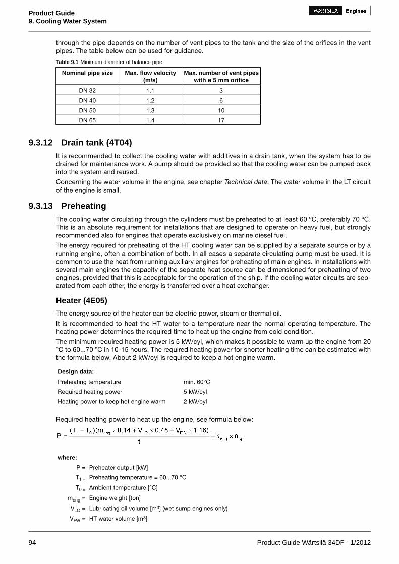
through the pipe depends on the number of vent pipes to the tank and the size of the orifices in the ventpipes. The table below can be used for guidance.
Table 9.1 Minimum diameter of balance pipe
Max. number of vent pipeswith ø 5 mm orifice
Max. flow velocity(m/s)
Nominal pipe size
31.1DN 32
61.2DN 40
101.3DN 50
171.4DN 65
9.3.12 Drain tank (4T04)It is recommended to collect the cooling water with additives in a drain tank, when the system has to bedrained for maintenance work. A pump should be provided so that the cooling water can be pumped backinto the system and reused.
Concerning the water volume in the engine, see chapter Technical data. The water volume in the LT circuitof the engine is small.
9.3.13 PreheatingThe cooling water circulating through the cylinders must be preheated to at least 60 ºC, preferably 70 ºC.This is an absolute requirement for installations that are designed to operate on heavy fuel, but stronglyrecommended also for engines that operate exclusively on marine diesel fuel.
The energy required for preheating of the HT cooling water can be supplied by a separate source or by arunning engine, often a combination of both. In all cases a separate circulating pump must be used. It iscommon to use the heat from running auxiliary engines for preheating of main engines. In installations withseveral main engines the capacity of the separate heat source can be dimensioned for preheating of twoengines, provided that this is acceptable for the operation of the ship. If the cooling water circuits are sep-arated from each other, the energy is transferred over a heat exchanger.
Heater (4E05)
The energy source of the heater can be electric power, steam or thermal oil.
It is recommended to heat the HT water to a temperature near the normal operating temperature. Theheating power determines the required time to heat up the engine from cold condition.
The minimum required heating power is 5 kW/cyl, which makes it possible to warm up the engine from 20ºC to 60...70 ºC in 10-15 hours. The required heating power for shorter heating time can be estimated withthe formula below. About 2 kW/cyl is required to keep a hot engine warm.
Design data:
min. 60°CPreheating temperature
5 kW/cylRequired heating power
2 kW/cylHeating power to keep hot engine warm
Required heating power to heat up the engine, see formula below:
where:
Preheater output [kW]P =
Preheating temperature = 60...70 °CT1 =
Ambient temperature [°C]T0 =
Engine weight [ton]meng =
Lubricating oil volume [m3] (wet sump engines only)VLO =
HT water volume [m3]VFW =
94 Product Guide Wärtsilä 34DF - 1/2012
Product Guide9. Cooling Water System

where:
Preheating time [h]t =
Engine specific coefficient = 1 kWkeng =
Number of cylindersncyl =
P < 3.5 kW/cylThe formula above should not be used for
Circulation pump for preheater (4P04)
Design data:
0.4 m3/h per cylinderCapacity
80 kPa (0.8 bar)Delivery pressure
Preheating unit (4N01)
A complete preheating unit can be supplied. The unit comprises:
• Electric or steam heaters
• Circulating pump
• Control cabinet for heaters and pump
• Set of thermometers
• Non-return valve
• Safety valve
Figure 9.8 Preheating unit, electric (3V60L0562C).
Dimensions [mm]Pipeconn.
Weight[kg]
Pump capacity[m³/h]
Heater capacity[kW]
EDCBAIn/outlet60 HZ50 Hz
4602406609001250DN4095131118
4802907007201050DN40100131122.5
4802907009001250DN40103131227
4802907007201050DN40105131230
4802907009001250DN40125131236
5103507557201250DN40145131245
5103507559001250DN40150131254
5504008059001260DN40187131272
5504008059001260DN40190131281
Product Guide Wärtsilä 34DF - 1/2012 95
Product Guide9. Cooling Water System

Dimensions [mm]Pipeconn.
Weight[kg]
Pump capacity[m³/h]
Heater capacity[kW]
EDCBAIn/outlet60 HZ50 Hz
5754508559001260DN402151312108
9.3.14 ThrottlesThrottles (orifices) are to be installed in all by-pass lines to ensure balanced operating conditions for tem-perature control valves. Throttles must also be installed wherever it is necessary to balance the waterflowbetween alternate flow paths.
9.3.15 Thermometers and pressure gaugesLocal thermometers should be installed wherever there is a temperature change, i.e. before and after heatexchangers etc.
Local pressure gauges should be installed on the suction and discharge side of each pump.
96 Product Guide Wärtsilä 34DF - 1/2012
Product Guide9. Cooling Water System

10. Combustion Air System
10.1 Engine room ventilationTo maintain acceptable operating conditions for the engines and to ensure trouble free operation of allequipment, attention to shall be paid to the engine room ventilation and the supply of combustion air.
The air intakes to the engine room must be located and designed so that water spray, rain water, dust andexhaust gases cannot enter the ventilation ducts and the engine room. For the minimum requirementsconcerning the engine room ventilation and more details, see the Dual Fuel Safety Concept and applicablestandards.
The amount of air required for ventilation is calculated from the total heat emission Φ to evacuate. To de-termine Φ, all heat sources shall be considered, e.g.:
• Main and auxiliary diesel engines
• Exhaust gas piping
• Generators
• Electric appliances and lighting
• Boilers
• Steam and condensate piping
• Tanks
It is recommended to consider an outside air temperature of no less than 35°C and a temperature rise of11°C for the ventilation air.
The amount of air required for ventilation (note also that the earlier mentioned demand on 30 air ex-changes/hour has to be fulfilled) is then calculated using the formula:
where:
air flow [m³/s]qv =
total heat emission to be evacuated [kW]Φ =
air density 1.13 kg/m³ρ =
specific heat capacity of the ventilation air 1.01 kJ/kgKc =
temperature rise in the engine room [°C]ΔT =
The heat emitted by the engine is listed in chapter Technical data.
The engine room ventilation air has to be provided by separate ventilation fans. These fans should preferablyhave two-speed electric motors (or variable speed). The ventilation can then be reduced according to outsideair temperature and heat generation in the engine room, for example during overhaul of the main enginewhen it is not preheated (and therefore not heating the room).
The ventilation air is to be equally distributed in the engine room considering air flows from points of deliverytowards the exits. This is usually done so that the funnel serves as exit for most of the air. To avoid stagnantair, extractors can be used.
It is good practice to provide areas with significant heat sources, such as separator rooms with their ownair supply and extractors.
Under-cooling of the engine room should be avoided during all conditions (service conditions, slowsteaming and in port). Cold draft in the engine room should also be avoided, especially in areas of frequentmaintenance activities. For very cold conditions a pre-heater in the system should be considered. Suitablemedia could be thermal oil or water/glycol to avoid the risk for freezing. If steam is specified as heatingmedium for the ship, the pre-heater should be in a secondary circuit.
Product Guide Wärtsilä 34DF - 1/2012 97
Product Guide10. Combustion Air System

10.1.1 Combustion air qualityThe air temperature at turbocharger inlet should be kept, as far as possible, between 15...35°C. Temporarilymax. 45°C is allowed.
10.2 Combustion air system designUsually, the combustion air is taken from the engine room through a filter on the turbocharger. This reducesthe risk for too low temperatures and contamination of the combustion air. It is important that the combustionair is free from sea water, dust, fumes, etc.
During normal operating conditions the air temperature at turbocharger inlet should be kept between15...35°C. Temporarily max. 45°C is allowed. For the required amount of combustion air, see sectionTechnical data.
The combustion air shall be supplied by separate combustion air fans, with a capacity slightly higher thanthe maximum air consumption. The combustion air mass flow stated in technical data is defined for anambient air temperature of 25°C. Calculate with an air density corresponding to 30°C or more when trans-lating the mass flow into volume flow. The expression below can be used to calculate the volume flow.
where:
combustion air volume flow [m³/s]qc =
combustion air mass flow [kg/s]m' =
air density 1.15 kg/m³ρ =
The fans should preferably have two-speed electric motors (or variable speed) for enhanced flexibility. Inaddition to manual control, the fan speed can be controlled by engine load.
In multi-engine installations each main engine should preferably have its own combustion air fan. Thus theair flow can be adapted to the number of engines in operation.
The combustion air should be delivered through a dedicated duct close to the turbocharger, directed towardsthe turbocharger air intake. The outlet of the duct should be equipped with a flap for controlling the directionand amount of air. Also other combustion air consumers, for example other engines, gas turbines andboilers shall be served by dedicated combustion air ducts.
If necessary, the combustion air duct can be connected directly to the turbocharger with a flexible connectionpiece. With this arrangement an external filter must be installed in the duct to protect the turbocharger andprevent fouling of the charge air cooler. The permissible total pressure drop in the duct is max. 1.5 kPa.The duct should be provided with a step-less change-over flap to take the air from the engine room or fromoutside depending on engine load and air temperature.
For very cold conditions heating of the supply air must be arranged. The combustion air fan is stoppedduring start of the engine and the necessary combustion air is drawn from the engine room. After starteither the ventilation air supply, or the combustion air supply, or both in combination must be able tomaintain the minimum required combustion air temperature. The air supply from the combustion air fan isto be directed away from the engine, when the intake air is cold, so that the air is allowed to heat up in theengine room.
10.2.1 Charge air shut-off valve, "rigsaver" (optional)In installations where it is possible that the combustion air includes combustible gas or vapour the enginescan be equipped with charge air shut-off valve. This is regulated mandatory where ingestion of flammablegas or fume is possible.
10.2.2 Condensation in charge air coolersAir humidity may condense in the charge air cooler, especially in tropical conditions. The engine equippedwith a small drain pipe from the charge air cooler for condensed water.
The amount of condensed water can be estimated with the diagram below.
98 Product Guide Wärtsilä 34DF - 1/2012
Product Guide10. Combustion Air System

Figure 10.1 Condensation in charge air coolersExample, according to the diagram:
At an ambient air temperature of 35°C and a relative humidityof 80%, the content of water in the air is 0.029 kg water/ kg dryair. If the air manifold pressure (receiver pressure) under theseconditions is 2.5 bar (= 3.5 bar absolute), the dew point will be55°C. If the air temperature in the air manifold is only 45°C, theair can only contain 0.018 kg/kg. The difference, 0.011 kg/kg(0.029 - 0.018) will appear as condensed water.
Product Guide Wärtsilä 34DF - 1/2012 99
Product Guide10. Combustion Air System

11. Exhaust Gas System
11.1 Internal exhaust gas systemFigure 11.1 Charge air and exhaust gas system, in-line engines (DAAE055614a)
System components
Cylinder04Air filter01
Waste gate valve05Turbocharger (TC)02
Charge air shut-off valve (optional)06Charge air cooler (CAC)03
Sensors and indicators
Air temperature, TC inletTE600Exhaust gas temperature after each cylinderTE50#1A
Charge air temperature, after CACTE601Exhaust gas temperature after TCTE517
Charge air shut-off valve position (optional)GS621TC speedSE518
Charge air pressure, after CACPT601
StandardPressure classSizePipe connections
ISO 7005-1PN6DN400Exhaust gas outlet501
DIN2353OD18Cleaning water to turbine502
DIN2353OD18Cleaning water to compressor509
DIN2353OD8Condensate after air cooler607
100 Product Guide Wärtsilä 34DF - 1/2012
Product Guide11. Exhaust Gas System

Figure 11.2 Charge air and exhaust gas system, V-engines (DAAE080922)
System components
Cylinder04Air filter01
Waste gate valve05Turbocharger (TC)02
Charge air shut-off valve (optional)06Charge air cooler (CAC)03
Sensors and indicators
Exhaust gas temperature, cyl #, B-bankTE50#1BExhaust gas temperature, TC inlet A-bankTE511
Cylinder liner temperature, A-bankTE7#1AExhaust gas temperature, TC outlet A-bankTE517
Cylinder liner temperature, B-bankTE7#1BTC speed, A-bankSE518
Air temperature, TC inletTE600Exhaust wastegate valve positionGT519
Charge air pressure, after CACPT601Exhaust gas temperature, TC inlet B-bankTE521
Charge air temperature, after CACTE601Exhaust gas temperature, TC outlet B-bankTE527
Charge air shut-off valve position, A-bank (optional)GS621TC speed, B-bankSE528
Charge air shut-off valve position, B-bank (optional)GS631Exhaust gas temperature, cyl #, A-bankTE50#1A
StandardPressure classSizePipe connections
ISO 7005-1PN6DN400Exhaust gas outlet501A/B
DIN2353OD18Cleaning water to turbine502
DIN2353OD18Cleaning water to compressor509
DIN2353OD8Condensate after air cooler607A/B
Product Guide Wärtsilä 34DF - 1/2012 101
Product Guide11. Exhaust Gas System

11.2 Exhaust gas outletFigure 11.3 Exhaust pipe connections (DAAE082913)
TC in free endTC typeEngine
0°, 45°, 90°NA297W 6L34DF
0°, 45°, 90°NA307W 9L34DF
0°, 45°, 90°NA297W 12V34DF
0°, 45°, 90°NA307W 16V34DF
Figure 11.4 Exhaust pipe, diameters and support (DAAE082783)
ØB [mm]ØA [mm]TC typeEngine
600DN400NA297W 6L34DF
700DN400NA307W 9L34DF
102 Product Guide Wärtsilä 34DF - 1/2012
Product Guide11. Exhaust Gas System

Figure 11.5 Exhaust pipe, diameters and support (DAAE082784, -86)
ØB [mm]ØA [mm]TC typeEngine
8002 x DN400NA297W 12V34DF
9002 x DN400NA307W 16V34DF
Product Guide Wärtsilä 34DF - 1/2012 103
Product Guide11. Exhaust Gas System

11.3 External exhaust gas systemEach engine should have its own exhaust pipe into open air. Backpressure, thermal expansion and supportingare some of the decisive design factors.
Flexible bellows must be installed directly on the turbocharger outlet, to compensate for thermal expansionand prevent damages to the turbocharger due to vibrations.
Duel Fuel engine1
Exhaust gas ventilation unit2
Rupture discs3
Exhaust gas boiler4
Silencer5
Figure 11.6 External exhaust gas system
11.3.1 System design - safety aspectsNatural gas may enter the exhaust system, if a malfunction occurs during gas operation. The gas may ac-cumulate in the exhaust piping and it could be ignited in case a source of ignition (such as a spark) appearsin the system. The external exhaust system must therefore be designed so that the pressure build-up incase of an explosion does not exceed the maximum permissible pressure for any of the components in thesystem. The engine can tolerate a pressure of at least 200 kPa. Other components in the system mighthave a lower maximum pressure limit. The consequences of a possible gas explosion can be minimizedwith proper design of the exhaust system; the engine will not be damaged and the explosion gases will besafely directed through predefined routes. The following guidelines should be observed, when designingthe external exhaust system:
• The piping and all other components in the exhaust system should have a constant upward slope toprevent gas from accumulating in the system. If horizontal pipe sections cannot be completely avoided,their length should be kept to a minimum. The length of a single horizontal pipe section should notexceed five times the diameter of the pipe. Silencers and exhaust boilers etc. must be designed sothat gas cannot accumulate inside.
• The exhaust system must be equipped with explosion relief devices, such as rupture discs, in orderto ensure safe discharge of explosion pressure. The outlets from explosion relief devices must be inlocations where the pressure can be safely released.
In addition the control and automation systems include the following safety functions:
• Before start the engine is automatically ventilated, i.e. rotated without injecting any fuel.
• During the start sequence, before activating the gas admission to the engine, an automatic combustioncheck is performed to ensure that the pilot fuel injection system is working correctly.
• The combustion in all cylinders is continuously monitored and should it be detected that all cylindersare not firing reliably, then the engine will automatically trip to diesel mode.
104 Product Guide Wärtsilä 34DF - 1/2012
Product Guide11. Exhaust Gas System

• The exhaust gas system is ventilated by a fan after the engine has stopped, if the engine was operatingin gas mode prior to the stop. The control of this function must be included in the external automationsystem.
11.3.2 Exhaust gas ventilation unit (5N01)An exhaust gas ventilation system is required to purge the exhaust piping after the engine has been stoppedin gas mode. The exhaust gas ventilation system is a class requirement. The ventilation unit is to consistof a centrifugal fan, a flow switch and a butterfly valve with position feedback. The butterfly valve has tobe of gas-tight design and able to withstand the maximum temperature of the exhaust system at the locationof installation.
The fan can be located inside or outside the engine room as close to the turbocharger as possible. Theexhaust gas ventilation sequence is automatically controlled.
Figure 11.7 Exhaust gas ventilation arrangement (3V76A2955)
Unit components
Ball valve5Switch1
Bellow6Fan2
Blind flange7Bellow3
Flange8Butterfly valve4
11.3.3 Relief devices - rupture discsExplosion relief devices such as rupture discs are to be installed in the exhaust system. Outlets are to dis-charge to a safe place remote from any source of ignition. The number and location of explosion reliefdevices shall be such that the pressure rise caused by a possible explosion cannot cause any damage tothe structure of the exhaust system.
This has to be verified with calculation or simulation. Explosion relief devices that are located indoors musthave ducted outlets from the machinery space to a location where the pressure can be safely released.The ducts shall be at least the same size as the rupture disc. The ducts shall be as straight as possible tominimize the back-pressure in case of an explosion.
For under-deck installation the rupture disc outlets may discharge into the exhaust casing, provided thatthe location of the outlets and the volume of the casing are suitable for handling the explosion pressurepulse safely. The outlets shall be positioned so that personnel are not present during normal operation, andthe proximity of the outlet should be clearly marked as a hazardous area.
11.3.4 PipingThe piping should be as short and straight as possible. Pipe bends and expansions should be smooth tominimise the backpressure. The diameter of the exhaust pipe should be increased directly after the bellowson the turbocharger. Pipe bends should be made with the largest possible bending radius; the bendingradius should not be smaller than 1.5 x D.
Product Guide Wärtsilä 34DF - 1/2012 105
Product Guide11. Exhaust Gas System

The recommended flow velocity in the pipe is 35…40 m/s at full output. If there are many resistance factorsin the piping, or the pipe is very long, then the flow velocity needs to be lower. The exhaust gas mass flowgiven in chapter Technical data can be translated to velocity using the formula:
Where:
gas velocity [m/s]v =
exhaust gas mass flow [kg/s]m' =
exhaust gas temperature [°C]T =
exhaust gas pipe diameter [m]D =
The exhaust pipe must be insulated with insulation material approved for concerned operation conditions,minimum thickness 30 mm considering the shape of engine mounted insulation. Insulation has to be con-tinuous and protected by a covering plate or similar to keep the insulation intact.
Closest to the turbocharger the insulation should consist of a hook on padding to facilitate maintenance.It is especially important to prevent the airstream to the turbocharger from detaching insulation, which willclog the filters.
After the insulation work has been finished, it has to be verified that it fulfils SOLAS-regulations. Surfacetemperatures must be below 220°C on whole engine operating range.
11.3.5 SupportingIt is very important that the exhaust pipe is properly fixed to a support that is rigid in all directions directlyafter the bellows on the turbocharger. There should be a fixing point on both sides of the pipe at the support.The bellows on the turbocharger may not be used to absorb thermal expansion from the exhaust pipe. Thefirst fixing point must direct the thermal expansion away from the engine. The following support must preventthe pipe from pivoting around the first fixing point.
Absolutely rigid mounting between the pipe and the support is recommended at the first fixing point afterthe turbocharger. Resilient mounts can be accepted for resiliently mounted engines with long bellows,provided that the mounts are self-captive; maximum deflection at total failure being less than 2 mm radialand 4 mm axial with regards to the bellows. The natural frequencies of the mounting should be on a safedistance from the running speed, the firing frequency of the engine and the blade passing frequency of thepropeller. The resilient mounts can be rubber mounts of conical type, or high damping stainless steel wirepads. Adequate thermal insulation must be provided to protect rubber mounts from high temperatures.When using resilient mounting, the alignment of the exhaust bellows must be checked on a regular basisand corrected when necessary.
After the first fixing point resilient mounts are recommended. The mounting supports should be positionedat stiffened locations within the ship’s structure, e.g. deck levels, frame webs or specially constructedsupports.
The supporting must allow thermal expansion and ship’s structural deflections.
11.3.6 Back pressureThe maximum permissible exhaust gas back pressure is stated in chapter Technical Data. The back pressurein the system must be calculated by the shipyard based on the actual piping design and the resistance ofthe components in the exhaust system. The exhaust gas mass flow and temperature given in chapterTechnical Data may be used for the calculation.
Each exhaust pipe should be provided with a connection for measurement of the back pressure. The backpressure must be measured by the shipyard during the sea trial.
11.3.7 Exhaust gas bellows (5H01, 5H03)Bellows must be used in the exhaust gas piping where thermal expansion or ship’s structural deflectionshave to be segregated. The flexible bellows mounted directly on the turbocharger outlet serves to minimise
106 Product Guide Wärtsilä 34DF - 1/2012
Product Guide11. Exhaust Gas System

the external forces on the turbocharger and thus prevent excessive vibrations and possible damage. Allexhaust gas bellows must be of an approved type.
11.3.8 SCR-unit (11N03)The exhaust gas piping must be straight at least 3...5 meters in front of the SCR unit. If both an exhaustgas boiler and a SCR unit will be installed, then the exhaust gas boiler shall be installed after the SCR. Ar-rangements must be made to ensure that water cannot spill down into the SCR, when the exhaust boileris cleaned with water.
In gas mode the SCR unit is not required as IMO Tier 3 and EPA Tier 4 are met.
11.3.9 Exhaust gas boilerIf exhaust gas boilers are installed, each engine should have a separate exhaust gas boiler. Alternatively,a common boiler with separate gas sections for each engine is acceptable.
For dimensioning the boiler, the exhaust gas quantities and temperatures given in chapter Technical datamay be used.
11.3.10 Exhaust gas silencer (5R09)The yard/designer should take into account that unfavorable layout of the exhaust system (length of straightparts in the exhaust system) might cause amplification of the exhaust noise between engine outlet and thesilencer. Hence the attenuation of the silencer does not give any absolute guarantee for the noise level afterthe silencer.
When included in the scope of supply, the standard silencer is of the absorption type, equipped with aspark arrester. It is also provided with an explosion relief vent (option), a soot collector and a condensedrain, but it comes without mounting brackets and insulation. The silencer should be mounted vertically.
The noise attenuation of the standard silencer is either 25 or 35 dB(A).
Figure 11.8 Exhaust gas silencer (DAAE087980)
Table 11.1 Typical dimensions of exhaust gas silencers, Attenuation 35 dB (A)
Weight [kg]B [mm]A [mm]D [mm]L [mm]NS
169026063513005510600
233027074515006550700
275028084017006530800
334029086018007270900
Flanges: DIN 2501
Product Guide Wärtsilä 34DF - 1/2012 107
Product Guide11. Exhaust Gas System

12. Turbocharger CleaningRegular water cleaning of the turbine and the compressor reduces the formation of deposits and extendsthe time between overhauls. Fresh water is injected into the turbocharger during operation. Additives,solvents or salt water must not be used and the cleaning instructions in the operation manual must becarefully followed.
Regular cleaning of the turbine is not necessary when operating on gas.
12.1 Turbine cleaning systemA dosing unit consisting of a flow meter and an adjustable throttle valve is delivered for each installation.The dosing unit is installed in the engine room and connected to the engine with a detachable rubber hose.The rubber hose is connected with quick couplings and the length of the hose is normally 10 m. One dosingunit can be used for several engines.
Water supply:
Fresh water
0.3 MPa (3 bar)Min. pressure
2 MPa (20 bar)Max. pressure
80 °CMax. temperature
15-30 l/min (depending on cylinder configuration)Flow
The turbocharges are cleaned one at a time on V-engines.
Figure 12.1 Turbocharger cleaning system (4V76A2937a)
SizePipe connectionsSystem components
OD18Cleaning water to turbine502Dosing unit with shut-off valve01
OD18Cleaning water to compressor509Rubber hose02
12.2 Compressor cleaning systemThe compressor side of the turbocharger is cleaned with the same equipment as the turbine.
108 Product Guide Wärtsilä 34DF - 1/2012
Product Guide12. Turbocharger Cleaning

13. Exhaust EmissionsExhaust emissions from the dual fuel engine mainly consist of nitrogen, carbon dioxide (CO2) and watervapour with smaller quantities of carbon monoxide (CO), sulphur oxides (SOx) and nitrogen oxides (NOx),partially reacted and non-combusted hydrocarbons and particulates.
13.1 Dual fuel engine exhaust componentsDue to the high efficiency and the clean fuel used in a dual fuel engine in gas mode, the exhaust gasemissions when running on gas are extremely low. In a dual fuel engine, the air-fuel ratio is very high, anduniform throughout the cylinders. Maximum temperatures and subsequent NOx formation are thereforelow, since the same specific heat quantity released to combustion is used to heat up a large mass of air.Benefitting from this unique feature of the lean-burn principle, the NOx emissions from the Wärtsilä 34DFare very low, complying with most existing legislation. In gas mode most stringent emissions of IMO, EPAand SECA are met, while in diesel mode the dual fuel engine is a normal diesel engine. In the following tablethere are some examples of the typical emissions levels of a 34DF engine.
Table 13.1 Typical emissions for Wärtsilä 34DF engine in gas operating mode
75 % load100% loadTypical emission levels*
1.41.3NOx (g/kWh)
469460CO2 (g/kWh)
Note:
* the CO2 emissions are depending on the quality of the gas used as a fuel. For a specific project value,please ask for information based on the actual gas specification.
To reach low emissions in gas operation, it is essential that the amount of injected diesel fuel is very small.The Wärtsilä DF engines therefore use a "micro-pilot" with less than 1% diesel fuel injected at nominal load.Thus the emissions of SOx from the dual fuel engine are negligable. When the engine is in diesel operatingmode, the emissions are in the same range as for any ordinary diesel engine, and the engine will be deliveredwith an EIAPP certificate to show compliance with the MARPOL Annex VI.
13.2 Marine exhaust emissions legislation
13.2.1 International Maritime Organization (IMO)The increasing concern over the air pollution has resulted in the introduction of exhaust emission controlsto the marine industry. To avoid the growth of uncoordinated regulations, the IMO (International MaritimeOrganization) has developed the Annex VI of MARPOL 73/78, which represents the first set of regulationson the marine exhaust emissions.
MARPOL Annex VI - Air Pollution
The MARPOL 73/78 Annex VI entered into force 19 May 2005. The Annex VI sets limits on Nitrogen Oxides,Sulphur Oxides and Volatile Organic Compounds emissions from ship exhausts and prohibits deliberateemissions of ozone depleting substances.
Nitrogen Oxides, NOx Emissions
The MARPOL 73/78 Annex VI regulation 13, Nitrogen Oxides, applies to diesel engines over 130 kW installedon ships built (defined as date of keel laying or similar stage of construction) on or after January 1, 2000.The NOx emissions limit is expressed as dependent on engine speed. IMO has developed a detailed NOxTechnical Code which regulates the enforcement of these rules.
EIAPP Certification
An EIAPP (Engine International Air Pollution Prevention) Certificate is issued for each engine showing thatthe engine complies with the NOx regulations set by the IMO.
When testing the engine for NOx emissions, the reference fuel is Marine Diesel Oil (distillate) and the testis performed according to ISO 8178 test cycles. Subsequently, the NOx value has to be calculated using
Product Guide Wärtsilä 34DF - 1/2012 109
Product Guide13. Exhaust Emissions

different weighting factors for different loads that have been corrected to ISO 8178 conditions. The usedISO 8178 test cycles are presented in the following table.
Table 13.2 ISO 8178 test cycles
100100100100100Speed (%)D2: Auxiliary engine
10255075100Power (%)
0.10.30.30.250.05Weightingfactor
100100100100Speed (%)E2: Diesel electric propul-sion or controllable pitchpropeller
255075100Power (%)
0.150.150.50.2Weightingfactor
IdleIntermediateRatedSpeedC1:"Variable -speed and -loadauxiliary engine application"
05075100105075100Torque (%)
0.150.10.10.10.10.150.150.15Weightingfactor
Engine family/group
As engine manufacturers have a variety of engines ranging in size and application, the NOx Technical Codeallows the organising of engines into families or groups. By definition, an engine family is a manufacturer’sgrouping, which through their design, are expected to have similar exhaust emissions characteristics i.e.,their basic design parameters are common. When testing an engine family, the engine which is expectedto develop the worst emissions is selected for testing. The engine family is represented by the parent engine,and the certification emission testing is only necessary for the parent engine. Further engines can be certifiedby checking document, component, setting etc., which have to show correspondence with those of theparent engine.
Technical file
According to the IMO regulations, a Technical File shall be made for each engine. The Technical File containsinformation about the components affecting NOx emissions, and each critical component is marked witha special IMO number. The allowable setting values and parameters for running the engine are also specifiedin the Technical File. The EIAPP certificate is part of the IAPP (International Air Pollution Prevention) Certi-ficate for the whole ship.
IMO NOx emission standards
The first IMO Tier 1 NOx emission standard entered into force in 2005 and applies to marine diesel enginesinstalled in ships constructed on or after 1.1.2000 and prior to 1.1.2011.
The Marpol Annex VI and the NOx Technical Code were then undertaken a review with the intention to furtherreduce emissions from ships. In the IMO MEPC meeting in April 2008 proposals for IMO Tier 2 and IMOTier 3 NOx emission standards were agreed. Final adoption for IMO Tier 2 and Tier 3 was taken by IMO/MEPC58 in October 2008.
The IMO Tier 2 NOx standard entered into force 1.1.2011 and replaced the IMO Tier 1 NOx emissionstandard globally. The Tier 2 NOx standard applies for marine diesel engines installed in ships constructedon or after 1.1.2011.
The IMO Tier 3 NOx emission standard will enter into force from 1 January 2016, but the Tier 3 standardwill only apply in designated special areas. These areas are not yet defined by the IMO. The IMO Tier 2 NOxemission standard will apply outside the Tier 3 designated areas. The Tier 3 NOx emission standard is notapplicable to recreational ships < 24 m and for ships with combined propulsion power < 750 kW subjectto satisfactory demonstration to Administration that the ship cannot meet Tier 3.
110 Product Guide Wärtsilä 34DF - 1/2012
Product Guide13. Exhaust Emissions

The NOx emissions limits in the IMO standards are expressed as dependent on engine speed. These areshown in figure 1.1 on next page.
Figure 13.1 IMO NOx emission limits
IMO Tier 1 NOx emission standard
The IMO Tier 1 NOx emission standard applies to ship built from year 2000 until end 2010.
The IMO Tier 1 NOx limit is defined as follows:
= 45 x rpm-0.2 when 130 < rpm < 2000NOx [g/kWh]
The NOx level is a weigthed awerage of NOx emissions at different loads, in accordance with the applicabletest cycle for the specific engine operating profile.
IMO Tier 2 NOx emission standard (new ships 2011)
The IMO Tier 2 NOx emission standard entered into force in 1.1.2011 and applies globally for new marinediesel engines > 130 kW installed in ships which keel laying date is 1.1.2011 or later.
The IMO Tier 2 NOx limit is defined as follows:
= 44 x rpm-0.23 when 130 < rpm < 2000NOx [g/kWh]
The NOx level is a weighted average of NOx emissions at different loads, and the test cycle is based on theengine operating profile according to ISO 8178 test cycles. IMO Tier 2 NOx emission levels correspondsto about 20% reduction from the IMO Tier 1 NOx emission standard. This reduction is reached with engineoptimization.
IMO Tier 3 NOx emission standard (new ships 2016, in designated areas)
The IMO Tier 3 NOx emission standard will enter into force from 1 January 2016. The IMO Tier 3 NOxstandard applies only for new marine diesel engines > 130 kW installed in ships which keel laying date is1.1.2016 or later when operating inside designated emission control areas (ECA).
The IMO Tier 3 NOx limit is defined as follows:
= 9 x rpm-0.2 when 130 < rpm < 2000NOx [g/kWh]
Product Guide Wärtsilä 34DF - 1/2012 111
Product Guide13. Exhaust Emissions

Dual fuel engines comply with IMO Tier 3 regulations. In diesel mode dual fuel engines comply with IMOTier 2.
The IMO Tier 3 NOx enission level corresponds to an 80% reduction from the IMO Tier 1 NOx emissionstandard. For diesel engines the reduction can be reached by applying a secondary exhaust gas emissioncontrol system. At present Selective Catalytic Reduction (SCR) is the only efficient way to reach the NOxreduction needed for the IMO Tier 3 standard.
Sulphur Oxides, SOx emissions
Marpol Annex VI has set a maximum global sulphur limit of currently 4,5% (until 1.1.2012) in weight for anyfuel used on board a ship. Annex VI also contains provisions allowing for special SOx Emission ControlAreas (SECA) to be established with more stringent controls on sulphur emissions. In a “SOx EmissionControl Area”, which currently comprises the Baltic Sea, the North Sea and the English Channel, the sulphurcontent of fuel oil used onboard a ship must currently not exceed 1% in weight. Alternatively, an exhaustgas cleaning system can be applied to reduce the total emissions of sulphur oxides from ships, includingboth auxiliary and main propulsion engines, calculated as the total weight of sulphur dioxide emissions.
The Marpol Annex VI has undertaken a review with the intention to further reduce emissions from ships. Inthe IMO MEPC 12 meeting in April 2008 proposals for new fuel oil sulphur limits were agreed. Final adoptionof the proposed sulphur limits was taken by IMO/MEPC 58 in October 2008. The upcoming limits for futurefuel oil sulphur contents are presented in the following table.
Table 13.3 Fuel sulphur caps
Date of implementationAreaFuel sulphur cap
1 July 2010SECA AreasMax. 1% S in fuel
1 January 2012GloballyMax 3.5% S in fuel
1 January 2015SECA AreasMax. 0.1% S in fuel
1 January 2020GloballyMax. 0.5% S in fuel
Abatement technologies including scrubbers are allowed as alternatives to low sulphur fuels.
13.2.2 Other LegislationsThere are also other local legislations in force in particular regions.
13.3 Methods to reduce exhaust emissionsAll standard Wärtsilä engines meet the NOx emission level set by the IMO (International Maritime Organisation)and most of the local emission levels without any modifications. Wärtsilä has also developed solutions tosignificantly reduce NOx emissions when this is required.
Diesel engine exhaust emissions can be reduced either with primary or secondary methods. The primarymethods limit the formation of specific emissions during the combustion process. The secondary methodsreduce emission components after formation as they pass through the exhaust gas system.
For dual fuel engines same methods as mentioned above can be used to reduce exhaust emissions whenrunning in diesel mode. In gas mode there is no need for scrubber or SCR.
Refer to the "Wärtsilä Environmental Product Guide" for information about exhaust gas emission controlsystems.
112 Product Guide Wärtsilä 34DF - 1/2012
Product Guide13. Exhaust Emissions

14. Automation SystemWärtsilä Unified Controls – UNIC is a modular embedded automation system. UNIC C3 is used for engineswith electronically controlled fuel injection and has a hardwired interface for control functions and a buscommunication interface for alarm and monitoring.
14.1 UNIC C3UNIC C3 is a fully embedded and distributed engine management system, which handles all control functionson the engine; for example start sequencing, start blocking, fuel injection, cylinder balancing, knock control,speed control, load sharing, normal stops and safety shutdowns.
The distributed modules communicate over a CAN-bus. CAN is a communication bus specifically developedfor compact local networks, where high speed data transfer and safety are of utmost importance.
The CAN-bus and the power supply to each module are both physically doubled on the engine for full re-dundancy.
Control signals to/from external systems are hardwired to the terminals in the main cabinet on the engine.Process data for alarm and monitoring are communicated over a Modbus TCP connection to externalsystems.
Figure 14.1 Architecture of UNIC C3
Short explanation of the modules used in the system:
Main Control Module. Handles all strategic control functions (such as start/stop sequencing andspeed/load control) of the engine.
MCM
Engine Safety Module handles fundamental engine safety, for example shutdown due to overspeedor low lubricating oil pressure. The safety module is the interface to the shutdown devices andbackup instruments.
ESM
Local Control Panel is equipped with push buttons and switches for local engine control, as well asindication of running hours and safety-critical operating parameters.
LCP
Local Display Unit offers a set of menus for retrieval and graphical display of operating data, calculateddata and event history. The module also handles communication with external systems over ModbusTCP.
LDU
Power Distribution Module handles fusing, power distribution, earth fault monitoring and EMC filtrationin the system. It provides two fully redundant 24 VDC supplies to all modules, sensors and controldevices.
PDM
Product Guide Wärtsilä 34DF - 1/2012 113
Product Guide14. Automation System

Input/Output Module handles measurements and limited control functions in a specific area on theengine.
IOM
Cylinder Control Module. Handles fuel injection control, and local measurements at the cylinderswhere it is used.
CCM
The above equipment and instrumentation are prewired on the engine. The ingress protection class is IP54.
14.1.1 External equipment
Power unit
Two redundant power supply converters/isolators are installed in a steel sheet cabinet for bulkheadmounting, protection class IP44.
14.1.2 Local control panel and local display unit
Operational functions available at the LCP:
• Local start
• Local stop
• Local emergency speed setting selectors (mechanical propulsion):
- Normal / emergency mode
- Decrease / Increase speed
• Local emergency stop
• Local shutdown reset
• Local mode selector switch with positions blow, blocked, local and remote
Positions:
- Local: Engine start and stop can be done only at the local control panel
- Remote: Engine can be started and stopped only remotely
- Blow: In this position it is possible to perform a manual slow turning by activating the start button.
- Blocked: Normal start of the engine is not possible
The LCP has back-up indication of the following parameters:
• Engine speed
• Turbocharger speed
• Running hours
• Lubricating oil pressure
• HT cooling water temperature
The local display unit has a set of menus for retrieval and graphical display of operating data, calculateddata and event history.
114 Product Guide Wärtsilä 34DF - 1/2012
Product Guide14. Automation System

Figure 14.2 Local control panel and local display unit
14.1.3 Engine safety systemThe engine safety system is based on hardwired logic with redundant design for safety-critical functions.The engine safety module handles fundamental safety functions, for example overspeed protection. It isalso the interface to the shutdown devices on the engine for all other parts of the control system.
Main features:
• Redundant design for power supply, speed inputs and stop solenoid control
• Fault detection on sensors, solenoids and wires
• Led indication of status and detected faults
• Digital status outputs
• Shutdown latching and reset
• Shutdown pre-warning
• Shutdown override (configuration depending on application)
• Analogue outputs for engine speed and turbocharger speed
• Adjustable speed switches
14.1.4 Power unitA power unit is delivered with each engine for separate installation. The power unit supplies DC power tothe electrical system on the engine and provides isolation from other DC systems onboard. The cabinet isdesigned for bulkhead mounting, protection degree IP44, max. ambient temperature 50°C.
Product Guide Wärtsilä 34DF - 1/2012 115
Product Guide14. Automation System

The power unit contains redundant power converters, each converter dimensioned for 100% load. At leastone of the two incoming supplies must be connected to a UPS. The power unit supplies the equipment onthe engine with 2 x 24 VDC and 2 x 110 VDC.
Power supply from ship's system:
• Supply 1: 230 VAC / abt. 1500 W
• Supply 2: 230 VAC / abt. 1500 W
14.1.5 Cabling and system overviewFigure 14.3 UNIC C3 overview
Table 14.1 Typical amount of cables
Cable types (typical)From <=> ToCable
3 x 2 x 0.75 mm2
1 x Ethernet CAT 5Engine <=> Integrated Automation SystemA
1 x 2 x 0.75 mm2
1 x 2 x 0.75 mm2
1 x 2 x 0.75 mm2
14 x 0.75 mm2
14 x 0.75 mm2
Engine <=> Propulsion Control SystemEngine <=> Power Management System / Main Switchboard
B
2 x 0.75 mm2Power unit <=> Integrated Automation SystemC
2 x 2.5 mm2 (power supply)2 x 2.5 mm2 (power supply)
Engine <=> Power UnitD
4 x 2 x 0.75 mm2
2 x 2 x 0.75 mm2
3 x 2 x 0.75 mm2
1 x Ethernet CAT5
Engine <=> Gas Valve UnitE
3 x 2 x 0.75 mm2
2 x 5 x 0.75 mm2Gas Valve Unit <=> Exhaust gas fan and pre-lube starterF
2 x 2 x 0.75 mm2
1 x Ethernet CAT5Gas Valve Unit <=> Integrated Automation SystemG
1 x 2 x 0.75 mm2Gas Valve Unit <=> Gas detection systemH
116 Product Guide Wärtsilä 34DF - 1/2012
Product Guide14. Automation System

Cable types (typical)From <=> ToCable
1 x 2 x 2.5 mm2
1 x 2 x 2.5 mm2
3 x 2 x 0.75 mm2
Power unit <=> Gas Valve UnitI
4 x 2 x 0.75 mm2Gas Valve Unit <=> Fuel gas supply systemJ
4 x 2 x 0.75 mm2
3 x 2.5 x 2.5 mm2Exhaust gas fan and pre-lube starter <=> Exhaust gas ventilationunit
K
NOTE! Cable types and grouping of signals in different cables will differ depending on installation.
* Dimension of the power supply cables depends on the cable length.
Power supply requirements are specified in section Power unit.
Figure 14.4 Signal overview (Main engine)
Product Guide Wärtsilä 34DF - 1/2012 117
Product Guide14. Automation System

Figure 14.5 Signal overview (Generating set)
14.2 Functions
14.2.1 Engine operating modesWärtsilä dual fuel engines can be requested by operator to run in two different operating modes:
• Gas operating mode (gas fuel + pilot fuel injection)
• Diesel operating mode (conventional diesel fuel injection + pilot fuel injection)
In addition, engine control and safety system or the blackout detection system can force the engine to runin backup operating mode (conventional diesel fuel injection only).
It is possible to transfer a running engine from gas- into diesel operating mode. Below a certain load limitthe engine can be transferred from diesel- into gas operating mode. The engine will automatically trip fromgas- into diesel operating mode (gas trip) in several alarm situations. Request for diesel operating modewill always override request for gas operating mode.
118 Product Guide Wärtsilä 34DF - 1/2012
Product Guide14. Automation System

The engine control system automatically forces the engine to backup operating mode (regardless of oper-ator choice of operating mode) in two cases:
• Pilot fuel injection system related fault is detected (pilot trip)
• Engine is started while the blackout-signal (from external source) is active
Figure 14.6 Principle of engine operating modes
14.2.2 Start
Start blocking
Starting is inhibited by the following functions:
• Stop lever in stop position
• Turning device engaged
• Pre-lubricating pressure low (override if black-out input is high and within last 5 minutes after thepressure has dropped below the set point of 0.5 bar)
• Stop signal to engine activated (safety shut-down, emergency stop, normal stop)
• External start block active
• Drive voltage low (override if black-out input is high)
• Main control module control voltage low
• Cylinder control module control voltage low
• Exhaust gas ventilation not performed
• HFO selected or fuel oil temperature > 70°C (Gas mode only)
• Charge air shut-off valve closed (optional device)
Start in gas operating mode
If the engine is ready to start in gas operating mode the output signals "engine ready for gas operation"(no gas trips are active) and "engine ready for start" (no start blockings are active) are activated. In gasoperating mode the following tasks are performed automatically:
• A GVU gas leakage test is performed
Product Guide Wärtsilä 34DF - 1/2012 119
Product Guide14. Automation System

• The starting air is activated
• Pilot fuel injection and pilot fuel pressure control is enabled
• Starting air is disengaged
• A combustion check is performed
• Gas admission is started and engine speed is raised to nominal
The start mode is interrupted in case of abnormalities during the start sequence. The start sequence takesabout 1.5 minutes to complete.
Start in diesel operating mode
When starting an engine in diesel operating mode the GVU check is omitted. The pilot combustion checkis performed to ensure correct functioning of the pilot fuel injection in order to enable later transfer into gasoperating mode. The start sequence takes about one minute to complete.
Start in blackout mode
When the blackout signal is active, the engine will be started in backup operating mode. The start is per-formed similarly to a conventional diesel engine, i.e. after receiving start signal the engine will start andramp up to nominal speed using only the conventional diesel fuel system. The blackout signal disablessome of the start blocks to get the engine running as quickly as possible. All checks during start-up thatare related to gas fuel system or pilot fuel system are omitted. Therefore the engine is not able to transferfrom backup operating mode to gas- or diesel operating mode before the gas and pilot system relatedsafety measures have been performed. This is done by stopping the engine and re-starting it in diesel- orgas operating mode.
After the blackout situation is over (i.e. when the first engine is started in backup operating mode, connectedto switchboard, loaded, and consequently blackout-signal cleared), more engines should be started, andthe one running in backup mode stopped and re-started in gas- or diesel operating mode.
14.2.3 Gas/diesel transfer control
Transfer from gas- to diesel-operating mode
The engine will transfer from gas to diesel operating mode at any load within 1s. This can be initiated inthree different ways: manually, by the engine control system or by the gas safety system (gas operationmode blocked).
Transfer from diesel- to gas-operating mode
The engine can be transferred to gas at engine load below 80% in case no gas trips are active, no pilot triphas occurred and the engine was not started in backup operating mode (excluding combustion check).
It is not recommended to run on gas when the engine load is low, as shown in figure 14.7.
Fuel transfers to gas usually takes about 2 minutes to complete, in order to minimize disturbances to thegas fuel supply systems.
The engine can run in backup operating mode in case the engine has been started with the blackout startinput active or a pilot trip has occurred. A transfer to gas operating mode can only be done after a combustioncheck, which is done by restarting the engine.
A leakage test on the GVU is automatically done before each gas transfer.
120 Product Guide Wärtsilä 34DF - 1/2012
Product Guide14. Automation System

Figure 14.7 Operating modes are load dependent
Points for consideration when selecting fuels
When selecting the fuel operating mode for the engine, or before transferring between operating modes,the operator should consider the following:
• To prevent an overload of the gas supply system, transfer one engine at a time to gas operating mode
• When running on gas, the engine load should be kept well above the automatic transfer lower limitin order to prevent unwanted transfer back to diesel
• When running several engines on gas, the load level should be kept such that no drop below theautomatic transfer load limit occur when an additional engine is brought on line
• Before a transfer command to gas operating mode is given to an engine, the PMS or operator mustensure that the other engines have enough ‘spinning reserve’ during the transfers. This because theengine may need to be unloaded below the upper transfer limit before transferring
• If engine load is within the transfer window, the engine will be able to switch fuels without unloading
• Whilst an engine is transferring, the starting and stopping of heavy electric consumers should beavoided
14.2.4 Stop, shutdown and emergency stop
Stop mode
Before stopping the engine, the control system shall first unload the engine slowly (if the engine is loaded),and after that open the generator breaker and send a stop signal to the engine.
Immediately after the engine stop signal is activated in gas operating mode, the GVU performs gas shut-off and ventilation. The pilot injection is active during the first part of the deceleration in order to ensurethat all gas remaining in engine is burned.
In case the engine was stopped in gas operating mode the exhaust gas system is ventilated to dischargeany unburned gas, if gas has been utilized within two minutes prior to the stop.
Shutdown mode
Shutdown mode is initiated automatically as a response to measurement signals.
In shutdown mode the clutch/generator breaker is opened immediately without unloading. The actionsfollowing a shutdown are similar to normal engine stop.
Shutdown mode must be reset by the operator and the reason for shutdown must be investigated andcorrected before re-start.
Product Guide Wärtsilä 34DF - 1/2012 121
Product Guide14. Automation System

Emergency stop mode
The sequence of engine stopping in emergency stop mode is similar to shutdown mode, except that alsothe pilot fuel injection is de-activated immediately upon stop signal.
Emergency stop is the fastest way of manually shutting down the engine. In case the emergency stop push-button is pressed, the button is automatically locked in pressed position.
To return to normal operation the push button must be pulled out and alarms acknowledged.
14.2.5 Speed control
Main engines (mechanical propulsion)
The electronic speed control is integrated in the engine automation system.
The remote speed setting from the propulsion control is an analogue 4-20 mA signal. It is also possible toselect an operating mode in which the speed reference can be adjusted with increase/decrease signals.
The electronic speed control handles load sharing between parallel engines, fuel limiters, and various othercontrol functions (e.g. ready to open/close clutch, speed filtering). Overload protection and control of theload increase rate must however be included in the propulsion control as described in the chapter "Operatingranges".
For single main engines a fuel rack actuator with a mechanical-hydraulic backup governor is specified.Mechanical back-up can also be specified for twin screw vessels with one engine per propeller shaft.Mechanical back-up is not an option in installations with two engines connected to the same reductiongear.
Generating sets
The electronic speed control is integrated in the engine automation system.
The load sharing can be based on traditional speed droop, or handled independently by the speed controlunits without speed droop. The later load sharing principle is commonly referred to as isochronous loadsharing. With isochronous load sharing there is no need for load balancing, frequency adjustment, or gen-erator loading/unloading control in the external control system.
In a speed droop system each individual speed control unit decreases its internal speed reference when itsenses increased load on the generator. Decreased network frequency with higher system load causes allgenerators to take on a proportional share of the increased total load. Engines with the same speed droopand speed reference will share load equally. Loading and unloading of a generator is accomplished by ad-justing the speed reference of the individual speed control unit. The speed droop is normally 4%, whichmeans that the difference in frequency between zero load and maximum load is 4%.
In isochronous mode the speed reference remains constant regardless of load level. Both isochronous loadsharing and traditional speed droop are standard features in the speed control and either mode can beeasily selected. If the ship has several switchboard sections with tie breakers between the different sections,then the status of each tie breaker is required for control of the load sharing in isochronous mode.
14.3 Alarm and monitoring signalsThe number of sensors and signals may vary depending on the application. The actual configuration ofsignals and the alarm levels are found in the project specific documentation supplied for all contractedprojects.
14.4 Electrical consumers
14.4.1 Motor starters and operation of electrically driven pumpsSeparators, preheaters, compressors and fuel feed units are normally supplied as pre-assembled units withthe necessary motor starters included. The engine turning device and various electrically driven pumps requireseparate motor starters. Motor starters for electrically driven pumps are to be dimensioned according tothe selected pump and electric motor.
Motor starters are not part of the control system supplied with the engine, but available as optional deliveryitems.
122 Product Guide Wärtsilä 34DF - 1/2012
Product Guide14. Automation System

Engine turning device (9N15)
The crankshaft can be slowly rotated with the turning device for maintenance purposes. The motor startermust be designed for reversible control of the motor. The electric motor ratings are listed in the table below.
Table 14.2 Electric motor ratings for engine turning device
Current [A]Power [kW]Frequency [Hz]Voltage [V]Engine type
5.0 / 5.32.2 / 2.650 / 603 x 400 / 440Wärtsilä 34DF
Pre-lubricating oil pump
The pre-lubricating oil pump must always be running when the engine is stopped. The pump shall startwhen the engine stops, and stop when the engine starts. The engine control system handles start/stop ofthe pump automatically via a motor starter.
It is recommended to arrange a back-up power supply from an emergency power source. Diesel generatorsserving as the main source of electrical power must be able to resume their operation in a black out situationby means of stored energy. Depending on system design and classification regulations, it may be permissibleto use the emergency generator.
For dimensioning of the pre-lubricating oil pump starter, the values indicated below can be used. For differentvoltages, the values may differ slightly.
Table 14.3 Electric motor ratings for pre-lubricating pump
Current [A]Power [kW]Frequency [Hz]Voltage [V]Engine type
14.07.5503 x 400in-line engines
14.68.6603 x 440
29.015.5503 x 400V-engines
30.518.0603 x 440
Exhaust gas ventilation unit
The exhaust gas ventilating unit is engine specific and includes an electric driven fan, flow switch andclosing valve. For further information, see chapter Exhaust gas system.
Gas valve unit (GVU)
The gas valve unit is engine specific and controls the gas flow to the engine. The GVU is equipped with abuilt-on control system. For further information, see chapter Fuel system.
Stand-by pump, lubricating oil (if installed) (2P04)
The engine control system starts the pump automatically via a motor starter, if the lubricating oil pressuredrops below a preset level when the engine is running. There is a dedicated sensor on the engine for thispurpose.
The pump must not be running when the engine is stopped, nor may it be used for pre-lubricating purposes.Neither should it be operated in parallel with the main pump, when the main pump is in order.
Stand-by pump, HT cooling water (if installed) (4P03)
The engine control system starts the pump automatically via a motor starter, if the cooling water pressuredrops below a preset level when the engine is running. There is a dedicated sensor on the engine for thispurpose.
Stand-by pump, LT cooling water (if installed) (4P05)
The engine control system starts the pump automatically via a motor starter, if the cooling water pressuredrops below a preset level when the engine is running. There is a dedicated sensor on the engine for thispurpose.
Product Guide Wärtsilä 34DF - 1/2012 123
Product Guide14. Automation System

Circulating pump for preheater (4P04)
If the main cooling water pump (HT) is engine driven, the preheater pump shall start when the engine stops(to ensure water circulation through the hot engine) and stop when the engine starts. The engine controlsystem handles start/stop of the pump automatically via a motor starter.
Sea water pumps (4P11)
The pumps can be stopped when all engines are stopped, provided that cooling is not required for otherequipment in the same circuit.
Lubricating oil separator (2N01)
Continuously in operation.
Feeder/booster unit (1N01)
Continuously in operation.
124 Product Guide Wärtsilä 34DF - 1/2012
Product Guide14. Automation System
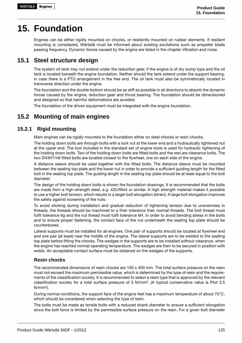
15. FoundationEngines can be either rigidly mounted on chocks, or resiliently mounted on rubber elements. If resilientmounting is considered, Wärtsilä must be informed about existing excitations such as propeller bladepassing frequency. Dynamic forces caused by the engine are listed in the chapter Vibration and noise.
15.1 Steel structure designThe system oil tank may not extend under the reduction gear, if the engine is of dry sump type and the oiltank is located beneath the engine foundation. Neither should the tank extend under the support bearing,in case there is a PTO arrangement in the free end. The oil tank must also be symmetrically located intransverse direction under the engine.
The foundation and the double bottom should be as stiff as possible in all directions to absorb the dynamicforces caused by the engine, reduction gear and thrust bearing. The foundation should be dimensionedand designed so that harmful deformations are avoided.
The foundation of the driven equipment must be integrated with the engine foundation.
15.2 Mounting of main engines
15.2.1 Rigid mountingMain engines can be rigidly mounted to the foundation either on steel chocks or resin chocks.
The holding down bolts are through-bolts with a lock nut at the lower end and a hydraulically tightened nutat the upper end. The tool included in the standard set of engine tools is used for hydraulic tightening ofthe holding down bolts. Two of the holding down bolts are fitted bolts and the rest are clearance bolts. Thetwo Ø43H7/n6 fitted bolts are located closest to the flywheel, one on each side of the engine.
A distance sleeve should be used together with the fitted bolts. The distance sleeve must be mountedbetween the seating top plate and the lower nut in order to provide a sufficient guiding length for the fittedbolt in the seating top plate. The guiding length in the seating top plate should be at least equal to the boltdiameter.
The design of the holding down bolts is shown the foundation drawings. It is recommended that the boltsare made from a high-strength steel, e.g. 42CrMo4 or similar. A high strength material makes it possibleto use a higher bolt tension, which results in a larger bolt elongation (strain). A large bolt elongation improvesthe safety against loosening of the nuts.
To avoid sticking during installation and gradual reduction of tightening tension due to unevenness inthreads, the threads should be machined to a finer tolerance than normal threads. The bolt thread mustfulfil tolerance 6g and the nut thread must fulfil tolerance 6H. In order to avoid bending stress in the boltsand to ensure proper fastening, the contact face of the nut underneath the seating top plate should becounterbored.
Lateral supports must be installed for all engines. One pair of supports should be located at flywheel endand one pair (at least) near the middle of the engine. The lateral supports are to be welded to the seatingtop plate before fitting the chocks. The wedges in the supports are to be installed without clearance, whenthe engine has reached normal operating temperature. The wedges are then to be secured in position withwelds. An acceptable contact surface must be obtained on the wedges of the supports.
Resin chocks
The recommended dimensions of resin chocks are 150 x 400 mm. The total surface pressure on the resinmust not exceed the maximum permissible value, which is determined by the type of resin and the require-ments of the classification society. It is recommended to select a resin type that is approved by the relevantclassification society for a total surface pressure of 5 N/mm2. (A typical conservative value is Ptot 3.5N/mm2).
During normal conditions, the support face of the engine feet has a maximum temperature of about 75°C,which should be considered when selecting the type of resin.
The bolts must be made as tensile bolts with a reduced shank diameter to ensure a sufficient elongationsince the bolt force is limited by the permissible surface pressure on the resin. For a given bolt diameter
Product Guide Wärtsilä 34DF - 1/2012 125
Product Guide15. Foundation

the permissible bolt tension is limited either by the strength of the bolt material (max. stress 80% of theyield strength), or by the maximum permissible surface pressure on the resin.
Steel chocks
The top plates of the foundation girders are to be inclined outwards with regard to the centre line of theengine. The inclination of the supporting surface should be 1/100 and it should be machined so that acontact surface of at least 75% is obtained against the chocks.
Recommended chock dimensions are 250 x 200 mm and the chocks must have an inclination of 1:100,inwards with regard to the engine centre line. The cut-out in the chocks for the clearance bolts shall be 44mm (M42 bolts), while the hole in the chocks for the fitted bolts shall be drilled and reamed to the correctsize (Ø43H7) when the engine is finally aligned to the reduction gear.
The design of the holding down bolts is shown the foundation drawings. The bolts are designed as tensilebolts with a reduced shank diameter to achieve a large elongation, which improves the safety againstloosening of the nuts.
Steel chocks with adjustable height
As an alternative to resin chocks or conventional steel chocks it is also permitted to install the engine onadjustable steel chocks. The chock height is adjustable between 45 mm and 65 mm for the approved typeof chock. There must be a chock of adequate size at the position of each holding down bolt.
126 Product Guide Wärtsilä 34DF - 1/2012
Product Guide15. Foundation

Figure 15.1 Main engine seating and fastening, in-line engines, steel chocks (DAAE085777)
Product Guide Wärtsilä 34DF - 1/2012 127
Product Guide15. Foundation

Number of pieces per engine
W 9L34DFW 6L34DF
22Fitted bolt
2014Clearance bolt
2216Round nut
2216Lock nut
22Distance sleeve
64Lateral support
2216Chocks
128 Product Guide Wärtsilä 34DF - 1/2012
Product Guide15. Foundation

Figure 15.2 Main engine seating and fastening, in-line engines, resin chocks (DAAE085778)
Product Guide Wärtsilä 34DF - 1/2012 129
Product Guide15. Foundation

Number of pieces per engine
W 9L34DFW 6L34DF
22Fitted bolt
2014Clearance bolt
2216Round nut
2216Lock nut
22Distance sleeve
64Lateral support
2216Chocks
130 Product Guide Wärtsilä 34DF - 1/2012
Product Guide15. Foundation

Figure 15.3 Main engine seating and fastening, V-engines, steel chocks (DAAE085776)
Product Guide Wärtsilä 34DF - 1/2012 131
Product Guide15. Foundation

Number of pieces per engine
W 16V34DFW 12V34DF
22Fitted bolt
1814Clearance bolt
2016Round nut
2016Lock nut
22Distance sleeve
64Lateral support
2016Chocks
132 Product Guide Wärtsilä 34DF - 1/2012
Product Guide15. Foundation

Figure 15.4 Main engine seating and fastening, V-engines, resin chocks (DAAE085781)
Product Guide Wärtsilä 34DF - 1/2012 133
Product Guide15. Foundation

Number of pieces per engine
W 16V34DFW 12V34DF
22Fitted bolt
1814Clearance bolt
2016Round nut
2016Lock nut
22Distance sleeve
64Lateral support
2016Chocks
134 Product Guide Wärtsilä 34DF - 1/2012
Product Guide15. Foundation
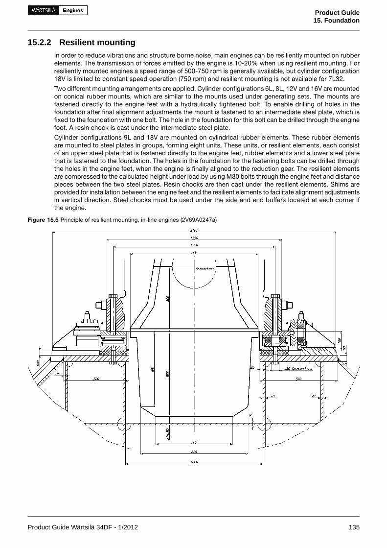
15.2.2 Resilient mountingIn order to reduce vibrations and structure borne noise, main engines can be resiliently mounted on rubberelements. The transmission of forces emitted by the engine is 10-20% when using resilient mounting. Forresiliently mounted engines a speed range of 500-750 rpm is generally available, but cylinder configuration18V is limited to constant speed operation (750 rpm) and resilient mounting is not available for 7L32.
Two different mounting arrangements are applied. Cylinder configurations 6L, 8L, 12V and 16V are mountedon conical rubber mounts, which are similar to the mounts used under generating sets. The mounts arefastened directly to the engine feet with a hydraulically tightened bolt. To enable drilling of holes in thefoundation after final alignment adjustments the mount is fastened to an intermediate steel plate, which isfixed to the foundation with one bolt. The hole in the foundation for this bolt can be drilled through the enginefoot. A resin chock is cast under the intermediate steel plate.
Cylinder configurations 9L and 18V are mounted on cylindrical rubber elements. These rubber elementsare mounted to steel plates in groups, forming eight units. These units, or resilient elements, each consistof an upper steel plate that is fastened directly to the engine feet, rubber elements and a lower steel platethat is fastened to the foundation. The holes in the foundation for the fastening bolts can be drilled throughthe holes in the engine feet, when the engine is finally aligned to the reduction gear. The resilient elementsare compressed to the calculated height under load by using M30 bolts through the engine feet and distancepieces between the two steel plates. Resin chocks are then cast under the resilient elements. Shims areprovided for installation between the engine feet and the resilient elements to facilitate alignment adjustmentsin vertical direction. Steel chocks must be used under the side and end buffers located at each corner ifthe engine.
Figure 15.5 Principle of resilient mounting, in-line engines (2V69A0247a)
Product Guide Wärtsilä 34DF - 1/2012 135
Product Guide15. Foundation

Figure 15.6 Principle of resilient mounting, V-engines (2V69A0248a)
136 Product Guide Wärtsilä 34DF - 1/2012
Product Guide15. Foundation

15.3 Mounting of generating sets
15.3.1 Generator feet designFigure 15.7 Distance between fixing bolts on generator (DAAE084469)
W 16V34DF Rmax[mm]
W 12V34DF Rmax[mm]
W 9L34DF Rmax[mm]
W 6L34DF Rmax[mm]H [mm]
---7151400
--8108101600
985985905-1800
10451045980-1950
--1090-2200
B [mm]C [mm]D [mm]E [mm]FG [mm]Engine
170100475Ø35M24 or M2785W L34DF
200130615Ø48M30100W V34DF
Product Guide Wärtsilä 34DF - 1/2012 137
Product Guide15. Foundation

15.3.2 Resilient mountingGenerating sets, comprising engine and generator mounted on a common base frame, are usually installedon resilient mounts on the foundation in the ship.
The resilient mounts reduce the structure borne noise transmitted to the ship and also serve to protect thegenerating set bearings from possible fretting caused by hull vibration.
The number of mounts and their location is calculated to avoid resonance with excitations from the gener-ating set engine, the main engine and the propeller.
NOTE! To avoid induced oscillation of the generating set, the following data must be sent by the shipyardto Wärtsilä at the design stage:
• main engine speed [RPM] and number of cylinders
• propeller shaft speed [RPM] and number of propeller blades
The selected number of mounts and their final position is shown in the generating set drawing.
138 Product Guide Wärtsilä 34DF - 1/2012
Product Guide15. Foundation

Figure 15.8 Recommended design of the generating set seating (3V46L0295d, DAAE020067a)
Rubber mounts
The generating set is mounted on conical resilient mounts, which are designed to withstand both compressionand shear loads. In addition the mounts are equipped with an internal buffer to limit the movements of thegenerating set due to ship motions. Hence, no additional side or end buffers are required.
The rubber in the mounts is natural rubber and it must therefore be protected from oil, oily water and fuel.
The mounts should be evenly loaded, when the generating set is resting on the mounts. The maximumpermissible variation in compression between mounts is 2.0 mm. If necessary, chocks or shims should beused to compensate for local tolerances. Only one shim is permitted under each mount.
The transmission of forces emitted by the engine is 10 -20% when using conical mounts. For the foundationdesign, see drawing 3V46L0295 (in-line engines) and 3V46L0294 (V-engines).
Product Guide Wärtsilä 34DF - 1/2012 139
Product Guide15. Foundation
Figure 15.9 Rubber mount, In-line engines (DAAE004230c)
Figure 15.10 Rubber mount, V-engines (DAAE018766b)
15.4 Flexible pipe connectionsWhen the engine or generating set is resiliently installed, all connections must be flexible and no gratingnor ladders may be fixed to the engine or generating set. When installing the flexible pipe connections,unnecessary bending or stretching should be avoided. The external pipe must be precisely aligned to thefitting or flange on the engine. It is very important that the pipe clamps for the pipe outside the flexibleconnection must be very rigid and welded to the steel structure of the foundation to prevent vibrations,which could damage the flexible connection.
140 Product Guide Wärtsilä 34DF - 1/2012
Product Guide15. Foundation

16. Vibration and NoiseWärtsilä 34DF generating sets comply with vibration levels according to ISO 8528-9. Main engines complywith vibration levels according to ISO 10816-6 Class 5.
16.1 External forces and couplesSome cylinder configurations produce external forces and couples. These are listed in the tables below.
The ship designer should avoid natural frequencies of decks, bulkheads and superstructures close to theexcitation frequencies. The double bottom should be stiff enough to avoid resonances especially with therolling frequencies.
Figure 16.1 Coordinate system
Table 16.1 External forces and couples
FZ[kN]
FY[kN]
Frequency[Hz]
MZ[kNm]
MY[kNm]
Frequency[Hz]
MZ[kNm]
MY[kNm]
Frequency[Hz]
Speed[rpm]
Engine
––
––
––
––
2426
2425
4145
4145
1212.5
720750
W 9L34DF
–0.1
––
–75
––
––
––
––
––
––
720750
W 12V34DF
33
44
4850
––
––
––
––
––
––
720750
W 16V34DF
– couples are zero or insignificant.
Product Guide Wärtsilä 34DF - 1/2012 141
Product Guide16. Vibration and Noise

16.2 Torque variationsTable 16.2 Torque variation at 100% load
MX[kNm]
Frequency[Hz]
MX[kNm]
Frequency[Hz]
MX[kNm]
Frequency[Hz]
Speed[rpm]
Engine
55
108112.5
1717
7275
2320
3637.5
720750
W 6L34DF
33
162168.75
88
108113
4747
5456.25
720750
W 9L34DF
55
108112.5
2727
7275
99
3637.5
720750
W 12V34DF
33
144150
1616
96100
3434
4850
720750
W 16V34DF
16.3 Mass moments of inertiaThe mass-moments of inertia of the main engines (including flywheel) are typically as follows:
J [kgm²]Engine
260...520W 6L34DF
520...610W 9L34DF
530...710W 12V34DF
550...730W 16V34DF
16.4 Air borne noiseThe airborne noise of the engine is measured as a sound power level according to ISO 9614-2. The resultsare presented with A-weighing in octave bands, reference level 1 pW. Two values are given; a minimumvalue and a 90% value. The minimum value is the lowest measured noise level. The 90% value indicatesthat 90% of all measured noise levels are below this value.
Figure 16.2 Typical sound power level for engine noise, W L34DF
142 Product Guide Wärtsilä 34DF - 1/2012
Product Guide16. Vibration and Noise

Figure 16.3 Typical sound power level for engine noise, W V34DF
16.5 Exhaust noiseFigure 16.4 Typical sound power level for exhaust noise, W L34DF
Product Guide Wärtsilä 34DF - 1/2012 143
Product Guide16. Vibration and Noise

Figure 16.5 Typical sound power level for exhaust noise, W V34DF
144 Product Guide Wärtsilä 34DF - 1/2012
Product Guide16. Vibration and Noise
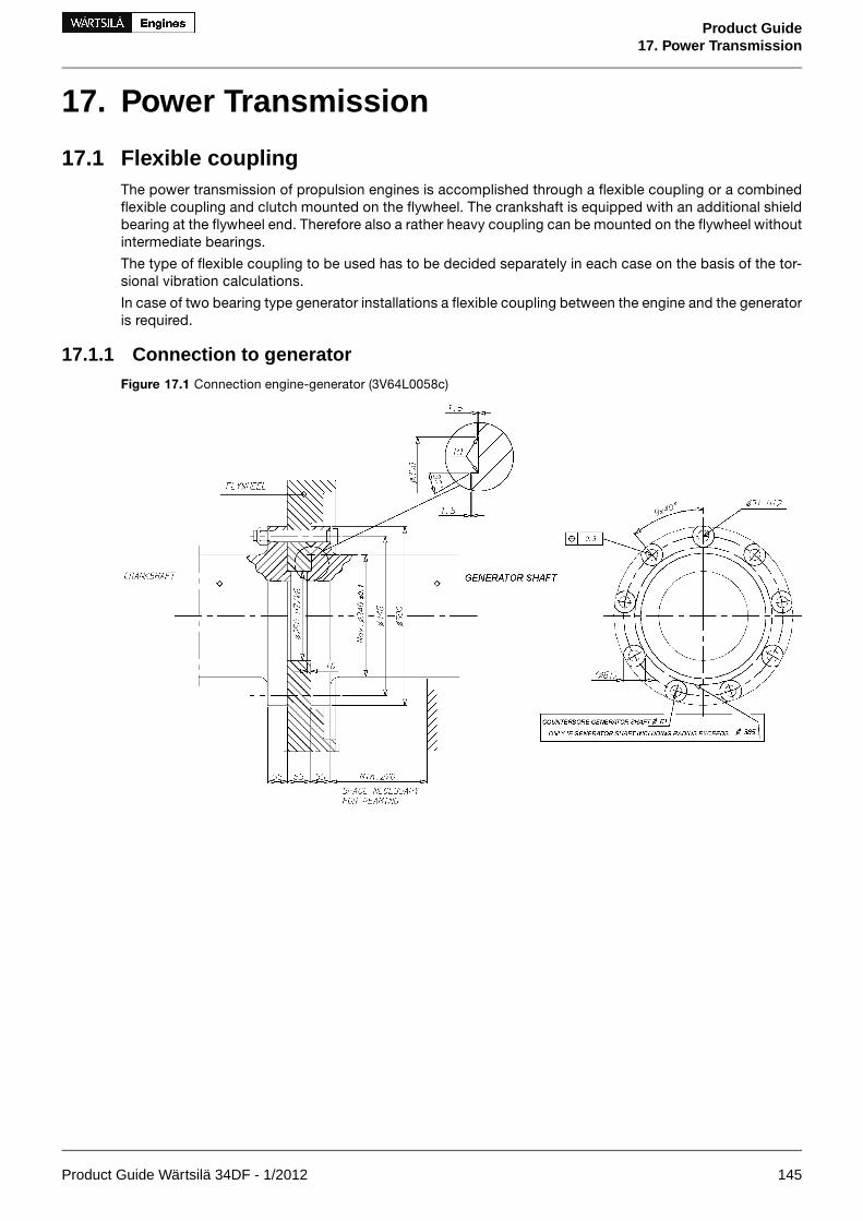
17. Power Transmission
17.1 Flexible couplingThe power transmission of propulsion engines is accomplished through a flexible coupling or a combinedflexible coupling and clutch mounted on the flywheel. The crankshaft is equipped with an additional shieldbearing at the flywheel end. Therefore also a rather heavy coupling can be mounted on the flywheel withoutintermediate bearings.
The type of flexible coupling to be used has to be decided separately in each case on the basis of the tor-sional vibration calculations.
In case of two bearing type generator installations a flexible coupling between the engine and the generatoris required.
17.1.1 Connection to generatorFigure 17.1 Connection engine-generator (3V64L0058c)
Product Guide Wärtsilä 34DF - 1/2012 145
Product Guide17. Power Transmission

Figure 17.2 Directives for generator end design (4V64F0003a)
17.2 Torque flangeIn mecanical propulsion applications, a torque meter has to be installed in order to measure the absorbedpower. The torque flange has an installation length of 300 mm for all cylinder configurations and is installedafter the flexible coupling.
17.3 ClutchIn many installations the propeller shaft can be separated from the diesel engine using a clutch. The useof multiple plate hydraulically actuated clutches built into the reduction gear is recommended.
A clutch is required when two or more engines are connected to the same driven machinery such as a re-duction gear.
To permit maintenance of a stopped engine clutches must be installed in twin screw vessels which canoperate on one shaft line only.
17.4 Shaft locking deviceTo permit maintenance of a stopped engine clutches must be installed in twin screw vessels which canoperate on one shaft line only. A shaft locking device should also be fitted to be able to secure the propellershaft in position so that wind milling is avoided. This is necessary because even an open hydraulic clutchcan transmit some torque. Wind milling at a low propeller speed (<10 rpm) can due to poor lubricationcause excessive wear of the bearings
The shaft locking device can be either a bracket and key or an easier to use brake disc with calipers. Inboth cases a stiff and strong support to the ship’s construction must be provided.
146 Product Guide Wärtsilä 34DF - 1/2012
Product Guide17. Power Transmission

Figure 17.3 Shaft locking device and brake disc with calipers
17.5 Power-take-off from the free endThe engine power can be taken from both ends of the engine. For in-line engines full engine power is alsoavailable at the free end of the engine. On V-engines the engine power at free end must be verified accordingto the torsional vibration calculations.
Figure 17.4 Power take off at free end (DAAE084566)
PTO shaft connected toL[mm]
D4[mm]
D3[mm]
D2[mm]
D1[mm]
Rating 1)
[kW]Engine
extension shaft with support bearing6502603002002004500In-lineengines flexible coupling, max weight at distance L = 900 kg7002603002002004500
extension shaft with support bearing8002603002002005000V-engines
flexible coupling, max weight at distance L = 390 kg10702603002002003500
Product Guide Wärtsilä 34DF - 1/2012 147
Product Guide17. Power Transmission

1) PTO shaft design rating, engine output may be lower
17.6 Input data for torsional vibration calculationsA torsional vibration calculation is made for each installation. For this purpose exact data of all componentsincluded in the shaft system are required. See list below.
Installation
• Classification
• Ice class
• Operating modes
Reduction gear
A mass elastic diagram showing:
• All clutching possibilities
• Sense of rotation of all shafts
• Dimensions of all shafts
• Mass moment of inertia of all rotating parts including shafts and flanges
• Torsional stiffness of shafts between rotating masses
• Material of shafts including tensile strength and modulus of rigidity
• Gear ratios
• Drawing number of the diagram
Propeller and shafting
A mass-elastic diagram or propeller shaft drawing showing:
• Mass moment of inertia of all rotating parts including the rotating part of the OD-box, SKF couplingsand rotating parts of the bearings
• Mass moment of inertia of the propeller at full/zero pitch in water
• Torsional stiffness or dimensions of the shaft
• Material of the shaft including tensile strength and modulus of rigidity
• Drawing number of the diagram or drawing
Main generator or shaft generator
A mass-elastic diagram or an generator shaft drawing showing:
• Generator output, speed and sense of rotation
• Mass moment of inertia of all rotating parts or a total inertia value of the rotor, including the shaft
• Torsional stiffness or dimensions of the shaft
• Material of the shaft including tensile strength and modulus of rigidity
• Drawing number of the diagram or drawing
Flexible coupling/clutch
If a certain make of flexible coupling has to be used, the following data of it must be informed:
• Mass moment of inertia of all parts of the coupling
• Number of flexible elements
• Linear, progressive or degressive torsional stiffness per element
• Dynamic magnification or relative damping
• Nominal torque, permissible vibratory torque and permissible power loss
• Drawing of the coupling showing make, type and drawing number
148 Product Guide Wärtsilä 34DF - 1/2012
Product Guide17. Power Transmission

Operational data
• Operational profile (load distribution over time)
• Clutch-in speed
• Power distribution between the different users
• Power speed curve of the load
17.7 Turning gearThe engine is equipped with an electrical driven turning gear, capable of turning the flywheel.
Product Guide Wärtsilä 34DF - 1/2012 149
Product Guide17. Power Transmission

18. Engine Room Layout
18.1 Crankshaft distancesMinimum crankshaft distances have to be followed in order to provide sufficient space between enginesfor maintenance and operation.
18.1.1 Main enginesFigure 18.1 Crankshaft distances, in-line engines (DAAE082974A)
A [mm]Engine type
2700W 6L34DF
2700W 9L34DF
150 Product Guide Wärtsilä 34DF - 1/2012
Product Guide18. Engine Room Layout
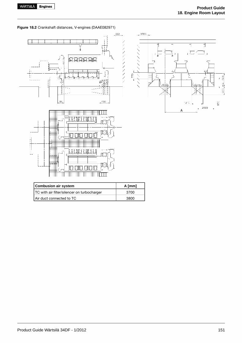
Figure 18.2 Crankshaft distances, V-engines (DAAE082971)
A [mm]Combusion air system
3700TC with air filter/silencer on turbocharger
3800Air duct connected to TC
Product Guide Wärtsilä 34DF - 1/2012 151
Product Guide18. Engine Room Layout

18.1.2 Generating setsFigure 18.3 Crankshaft distances, in-line engines (DAAE082973)
FED ***C ***B ***A ***Engine type
17004102800191016601600W 6L34DF
20001102800251022602200W 9L34DF
All dimensions in mm.
*** Dependent on the generator type.
152 Product Guide Wärtsilä 34DF - 1/2012
Product Guide18. Engine Room Layout

Figure 18.4 Crankshaft distances, V-engines (DAAE082970)
CBAEngine type
min. 380026202200W 12V34DF
min. 380026202200W 16V34DF
All dimensions in mm.
18.1.3 Father-and-son arrangementWhen connecting two engines of different type and/or size to the same reduction gear the minimumcrankshaft distance has to be evaluated case by case. However, some general guidelines can be given:
• It is essential to check that all engine components can be dismounted. The most critical are usuallyturbochargers and charge air coolers.
• When using a combination of in-line and v-engine, the operating side of in-line engine should facethe v-engine in order to minimize the distance between crankshafts.
• Special care has to be taken checking the maintenance platform elevation between the engines toavoid structures that obstruct maintenance.
Product Guide Wärtsilä 34DF - 1/2012 153
Product Guide18. Engine Room Layout

Figure 18.5 Example of father-and-son arrangement, 9L34DF + 12V34DF, TC in free end (DAAE082972)
All dimensions in mm. *) 50mm for clearance included.
18.1.4 Distance from adjacent intermediate/propeller shaftSome machinery arrangements feature an intermediate shaft or propeller shaft running adjacent to engine.To allow adequate space for engine inspections and maintenance there has to be sufficient free spacebetween the intermediate/propeller shaft and the engine. To enable safe working conditions the shaft hasto be covered. It must be noticed that also dimensions of this cover have to be taken into account whendetermining the shaft distances in order to fulfil the requirement for minimum free space between the shaftand the engine.
154 Product Guide Wärtsilä 34DF - 1/2012
Product Guide18. Engine Room Layout

Figure 18.6 Main engine arrangement, in-line engines (DAAE086973B)
Notes:All dimensions in mm.Intermediate shaft diameter to be determined case by case* Depending on type of shaft bearing** Depends on the type of gearbox
D*CB**A**Engine type
148027001880940W 6L34DF
148027001880940W 9L34DF
Figure 18.7 Main engine arrangement, in-line engines (DAAE086972B)
Notes:All dimensions in mm.Intermediate shaft diameter to be determined case by case.* Depends on type of shaft bearing** Depends on the type of gearbox
D*CB**A**Engine type
1480270037601880W 6L34DF
1480270037601880W 9L34DF
Product Guide Wärtsilä 34DF - 1/2012 155
Product Guide18. Engine Room Layout

Figure 18.8 Main engine arrangement, V-engines (DAAE083977)
Figure 18.9 Main engine arrangement, V-engines (DAAE083975)
Notes:All dimensions in mm.Intermediate shaft diameter to be determined case by case* Depends on type of gearbox** Depends on type of shaft bearing
156 Product Guide Wärtsilä 34DF - 1/2012
Product Guide18. Engine Room Layout

18.2 Space requirements for maintenance
18.2.1 Working space around the engineThe required working space around the engine is mainly determined by the dismounting dimensions ofengine components, and space requirement of some special tools. It is especially important that no ob-structive structures are built next to engine driven pumps, as well as camshaft and crankcase doors.
However, also at locations where no space is required for dismounting of engine parts, a minimum of 1000mm free space is recommended for maintenance operations everywhere around the engine.
18.2.2 Engine room height and lifting equipmentThe required engine room height is determined by the transportation routes for engine parts. If there issufficient space in transverse and longitudinal direction, there is no need to transport engine parts over therocker arm covers or over the exhaust pipe and in such case the necessary height is minimized.
Separate lifting arrangements are usually required for overhaul of the turbocharger since the crane travelis limited by the exhaust pipe. A chain block on a rail located over the turbocharger axis is recommended.
18.2.3 Maintenance platformsIn order to enable efficient maintenance work on the engine, it is advised to build the maintenance platformson recommended elevations. The width of the platforms should be at minimum 800 mm to allow adequateworking space. The surface of maintenance platforms should be of non-slippery material (grating or chequerplate).
18.3 Transportation and storage of spare parts and toolsTransportation arrangement from engine room to storage and workshop has to be prepared for heavy enginecomponents. This can be done with several chain blocks on rails or alternatively utilising pallet truck ortrolley. If transportation must be carried out using several lifting equipment, coverage areas of adjacentcranes should be as close as possible to each other.
Engine room maintenance hatch has to be large enough to allow transportation of main components to/fromengine room.
It is recommended to store heavy engine components on slightly elevated adaptable surface e.g. woodenpallets. All engine spare parts should be protected from corrosion and excessive vibration.
On single main engine installations it is important to store heavy engine parts close to the engine to makeoverhaul as quick as possible in an emergency situation.
18.4 Required deck area for service workDuring engine overhaul some deck area is required for cleaning and storing dismantled components. Sizeof the service area is dependent of the overhauling strategy chosen, e.g. one cylinder at time, one bank attime or the whole engine at time. Service area should be plain steel deck dimensioned to carry the weightof engine parts.
Product Guide Wärtsilä 34DF - 1/2012 157
Product Guide18. Engine Room Layout

18.4.1 Service space requirement for the in-line engineFigure 18.10 Service space requirement, turbocharger in free end (DAAE083978)
158 Product Guide Wärtsilä 34DF - 1/2012
Product Guide18. Engine Room Layout

18.4.2 Service space requirement for the V-engineFigure 18.11 Service space requirement, turbocharger in free end (DAAE083976)
Product Guide Wärtsilä 34DF - 1/2012 159
Product Guide18. Engine Room Layout

19. Transport Dimensions and Weights
19.1 Lifting of main enginesFigure 19.1 Lifting of main engines, in-line engines (DAAE083962)
E2*E1*D3D2*D1*CBAEngine
2940294015209809804902990540W 6L34DF
4410392020109804904904460540W 9L34DF
All dimensions in mm. Transport bracket weight: 890 kg.
Rear side (B-bank)1 =*
Operating side (A-bank)2 =
160 Product Guide Wärtsilä 34DF - 1/2012
Product Guide19. Transport Dimensions and Weights

Figure 19.2 Lifting of main engines, V-engines (DAAE083962)
F2*F1*E2*E1*D2*D1*CBAEngine
159417063330333053010905603430630W 12V34DF
215422664450445053010905604550630W 16V34DF
All dimensions in mm. Transport bracket weight: dry oil sump = 935 kg, wet oil sump = 1060 kg.
Rear side (B-bank)1 =*
Operating side (A-bank)2 =
Product Guide Wärtsilä 34DF - 1/2012 161
Product Guide19. Transport Dimensions and Weights

19.2 Lifting of generating setsFigure 19.3 Lifting of generating sets (DAAE083966, -69)
W [mm]L [mm]H [mm]Engine
2245...28453700...60006550...6900W L34DF
2975...32754500...65008000...8480W V34DF
162 Product Guide Wärtsilä 34DF - 1/2012
Product Guide19. Transport Dimensions and Weights

19.3 Engine componentsTable 19.1 Lubricating oil insert (DAAE083974)
Weight [kg]Dimensions [mm]Engine
BA
105369.4650W 6L34DF
120369.41140W 9L34DF
250479.41338W 12V34DF
250479.41338W 16V34DF
Table 19.2 Charge air cooler insert (DAAE083974)
Weight [kg]Dimensions [mm]Engine
EDC
500436672963W 6L34DF
500594790963W 9L34DF
8506006002056W 12V34DF
9506006002056W 16V34DF
Table 19.3 Turbocharger (DAAE083974)
Weight (kg)Dimensions [mm]Engine
KHGF
7737668616631017W 6L34DF
7837668616631017W 9L34DF
2 x 7737668616631017W 12V34DF
2 x 7837668616631017W 16V34DF
Product Guide Wärtsilä 34DF - 1/2012 163
Product Guide19. Transport Dimensions and Weights

Figure 19.4 Major spare parts (DAAE083973)
Weight [kg]DescriptionItem NoWeight [kg]DescriptionItem no
11.5Starting valve9153.5Connecting rod1
8.5Main bearing shell1074Piston2
127Split gear wheel11253Cylinder liner3
31Small intermediate gear12410Cylinder head4
156Large intermediate gear133Inlet valve5
103Camshaft gear wheel142.8Exhaust valve6
1.5Piston ring set1537Injection pump7
0.5Piston ring15.5Injection valve8
164 Product Guide Wärtsilä 34DF - 1/2012
Product Guide19. Transport Dimensions and Weights

20. Product Guide AttachmentsThis and other product guides can be accessed on the internet, from the Business Online Portal atwww.wartsila.com. Product guides are available both in web and PDF format. Drawings are available inPDF and DXF format, and in near future also as 3D models. Consult your sales contact at Wärtsilä to getmore information about the product guides on the Business Online Portal.
The attachments are not available in the printed version of the product guide.
Product Guide Wärtsilä 34DF - 1/2012 165
Product Guide20. Product Guide Attachments

21. ANNEX
21.1 Unit conversion tablesThe tables below will help you to convert units used in this product guide to other units. Where the conversionfactor is not accurate a suitable number of decimals have been used.
Table 21.2 Mass conversion factors
Multiply byToConvert from
2.205lbkg
35.274ozkg
Table 21.1 Length conversion factors
Multiply byToConvert from
0.0394inmm
0.00328ftmm
Table 21.4 Volume conversion factors
Multiply byToConvert from
61023.744in3m3
35.315ft3m3
219.969Imperial gallonm3
264.172US gallonm3
1000l (litre)m3
Table 21.3 Pressure conversion factors
Multiply byToConvert from
0.145psi (lbf/in2)kPa
20.885lbf/ft2kPa
4.015inch H2OkPa
0.335foot H2OkPa
101.972mm H2OkPa
0.01barkPa
Table 21.6 Moment of inertia and torque conversion factors
Multiply byToConvert from
23.730lbft2kgm2
737.562lbf ftkNm
Table 21.5 Power conversion factors
Multiply byToConvert from
1.360hp (metric)kW
1.341US hpkW
Table 21.8 Flow conversion factors
Multiply byToConvert from
4.403US gallon/minm3/h (liquid)
0.586ft3/minm3/h (gas)
Table 21.7 Fuel consumption conversion factors
Multiply byToConvert from
0.736g/hphg/kWh
0.00162lb/hphg/kWh
Table 21.10 Density conversion factors
Multiply byToConvert from
0.00834lb/US gallonkg/m3
0.01002lb/Imperial gallonkg/m3
0.0624lb/ft3kg/m3
Table 21.9 Temperature conversion factors
CalculateToConvert from
F = 9/5 *C + 32F°C
K = C + 273.15K°C
21.1.1 Prefix
Table 21.11 The most common prefix multipliers
FactorSymbolName
1012Ttera
109Ggiga
106Mmega
103kkilo
10-3mmilli
10-6μmicro
10-9nnano
166 Product Guide Wärtsilä 34DF - 1/2012
Product Guide21. ANNEX

21.2 Collection of drawing symbols used in drawingsFigure 21.1 List of symbols (DAAE000806c)
Product Guide Wärtsilä 34DF - 1/2012 167
Product Guide21. ANNEX

168 Product Guide Wärtsilä 34DF - 1/2012
Product Guide
This page intentionally left blank


WÄRTSILÄ® is a registered trademark. Copyright © 2011 Wärtsilä Corporation.
Wärtsilä is a global leader in complete lifecycle power solutions
for the marine and energy markets. By emphasising technological
innovation and total efficiency, Wärtsilä maximises the environmental
and economic performance of the vessels and power plants of its
customers. Wärtsilä is listed on the NASDAQ OMX Helsinki, Finland.