water based polyurethane multi-functional composites
TRANSCRIPT

Water Based Polyurethane Multi-Functional
Composites
By
Pengxiang Si
A thesis
presented to the University of Waterloo
in fulfillment of the
thesis requirement for the degree of
Doctor of Philosophy
in
Chemical Engineering
Waterloo, Ontario, Canada, 2020
© Pengxiang Si 2020

ii
Examining Committee Membership
The following served on the Examining Committee for this thesis. The decision of the
Examining Committee is by majority vote.
External Examiner Prof. Jun Yang
Mechanical and Materials Engineering,
University of Western Ontario
Supervisor(s) Prof. Boxin Zhao
Chemical Engineering, University of Waterloo
Internal Member Prof. Jeffrey Gostick
Chemical Engineering, University of Waterloo
Internal Member Prof. Xianshe Feng
Chemical Engineering, University of Waterloo
Internal-external Member Prof. Juewen Liu
Chemistry, University of Waterloo

iii
Author’s Declaration
I hereby declare that this thesis consists of materials, all of which I authored or co-authored: see
Statement of Contributions included in the thesis. This is a true copy of the thesis, including any required
final revisions, as accepted by my examiners.
I understand that my thesis may be made electronically available to the public.

iv
Statement of Contributions
The research work described in Chapter 3 has been published in
Pengxiang Si, Li Chen, Boxin Zhao, Alex Chen, John Persic and Robert Lyn. Stretchable Polyurethane-
Based Conductive Ink for E-Textile Applications. Journal of Surface Mount Technology. 2019, 32-1.
The research work described in Chapter 5 has been submitted in ACS applied materials & interfaces.
I am the first author of all these journal publications.
List of publications
Pengxiang Si, Li Chen, Boxin Zhao, Alex Chen, John Persic and Robert Lyn. “Stretchable Polyurethane-
Based Conductive Ink for E-Textile Applications.” Journal of Surface Mount Technology. 2019, 32-1.
Pengxiang Si, Li Yu, Boxin Zhao. “Poly methacrylic acid sodium salt (PMANa)/Polyurethane (PU)
Latex-Polyelectrolyte Colloid Systems Enabling One-Pot Fabrication of Non-periodic Structured
Mechanoresponsive Smart Windows”. Submitted to ACS applied materials & interfaces.
Pengxiang Si, Li Chen, Li Yu, Boxin Zhao. "Dual Colorimetric and Conductometric Responses of Silver-
Decorated Polypyrrole Nanowires for Sensing Organic Solvents of Varied Polarities." ACS applied
materials & interfaces 10, no. 35 (2018): 29227-29232.
Pengxiang Si, Josh Trinidad, Li Chen, Brenda Lee, Alex Chen, John Persic, Robert Lyn, Zoya Leonenko,
Boxin Zhao. "PEDOT: PSS nano-gels for highly electrically conductive silver/epoxy composite
adhesives." Journal of Materials Science: Materials in Electronics 29, no. 3 (2018): 1837-1846.
Li Yu, Pengxiang Si, Lukas Bauman, Boxin Zhao. " Synergetic Combination of Interfacial Engineering
and Shape-Changing Modulation for Biomimetic Soft Robotic Devices." Langmuir 36.13 (2020): 3279-
3291." Langmuir (2020).
Bona Deng, Pengxiang Si, Lukas Bauman, Jun Luo, Mingjun Rao, Zhiwei Peng, Tao Jiang, Guanghui Li,
Boxin Zhao. "Photocatalytic activity of CaTiO3 derived from roasting process of bauxite
residue." Journal of Cleaner Production 244 (2020): 118598.
Li Yu, Ran Peng, Geoffrey Rivers, Che Zhang, Pengxiang Si, and Boxin Zhao. "Multifunctional Liquid
Crystal Polymer Network Soft Actuators." Journal of Materials Chemistry A (2020).
Li Chen, Pengxiang Si, and Boxin Zhao. "Biotemplated synthesis of cellulose nanocrystal@ PVP-
assisted polydopamine@ Ag nanoparticle as conductive composites." Journal of Materials Science:
Materials in Electronics 30, no. 13 (2019): 12077-12086.
Li Yu, Hamed Shahsavan, Geoffrey Rivers, Che Zhang, Pengxiang Si, and Boxin Zhao. "Programmable
3D shape changes in liquid crystal polymer networks of uniaxial orientation." Advanced Functional
Materials 28, no. 37 (2018): 1802809.

v
Abstract
Polyurethanes (PUs) are a class of versatile polymers that exhibit various mechanical, physical,
chemical and biological properties depending on their structure and morphology. Polyurethanes
(PUs) have been employed in a variety of industrial applications including foams, coatings,
textiles, machinery, sporting, transportation, vehicles and construction. However, the potentials
of PUs in the emerging technology fields such as soft and wearable electronics, energy storage
devices, biosensors, actuators, photovoltaic devices and stimuli-responsive materials are largely
unexplored. The major objective of the thesis research is to develop PU composites for such
emerging applications as e-textiles, self-healing electronics, and smart windows. In this project,
we select water-based polyurethane (WPU) as the main polymer matrix to develop a variety of
ink systems for multiple applications.
Firstly, to investigate the application of WPU in flexible and stretchable electronics, we develop
a WPU-silver and WPU-polypyrrole (PPy) conductive ink for textile. The effective penetration
of obtained ink makes the textile conductive and mechanically robust. The electrical conductivity
of the PU-silver textile is high but drops significantly under stretching due to the intrinsically
rigid property of metal. In contrast, the WPU-PPy textile shows a stable conductive performance
under large elongation, however the electrical conductivity is four orders of magnitude lower
than that of WPU-silver textile.
Secondly, taking advantage of the ionic properties of WPU, we develop a self-healing elastomer
through WPU/polyethylenimine (PEI) latex polyelectrolyte coacervation system, which contains
opposite charges but is stable in water solution. Self-healing is achieved via water through two
types of non-covalent bonds: ionic interaction between WPU and PEI, and polymer
entanglement of WPU itself. This WPU-PEI dispersion can be combined with conductive filler

vi
such as silver flakes for printable self-healing soft antenna, indicating the potential applications
in soft electronics industries.
Finally, we replace the positively charged PEI with negatively charged poly methacrylic acid
sodium salt (PMANa) to functionalize the WPU dispersion. The WPU-PMANa film shows a
sharp change in transparency under mechanical strain, which can be used as robust
mechanoresponsive smart windows. Additionally, the polyurethane smart window is multi-
functional, its potential applications in the field of camouflage and dynamic optical gratings have
been explored.

vii
Acknowledgements
I wish to express my deepest gratitude to my supervisor, Prof. Boxin Zhao, for his convincing
guidance and support during my four-year Ph.D. study. His professional, honest, disciplined
working style and humble, gentle, cultivated personality encourage me on both my research and
life. Without his persistent assistance, the goal of this project would not have been realized. I
would like to show my gratitude to Prof. Qingsha Cheng for the opportunity to work in his
laboratory at the Southern University of Science and Technology, Shenzhen, China. This
multidisciplinary work broadened my knowledge and insights on the research project and field of
antenna. Special thanks to all my labmates and colleagues in Waterloo and Shenzhen for their
timely help and useful suggestions, especially to Dr. Li Chen, Dr. Li Yu and Dr. Zengqian Shi.

viii
Dedication
I dedicate this dissertation to my beloved wife Yiran Zhou for always being by my side; to my
parents Jianguo Si, Wen Jin and parents-in-law Yonghui Zhou, Jingzi Yang for their endless
love, support and sacrifices; to my newborn son Joseph Si for his innocent smile.

ix
Table of Contents
Examining Committee Membership ............................................................................................... ii
Author’s Declaration .................................................................................................................. iii
Statement of Contributions......................................................................................................... iv
List of publications ..................................................................................................................... iv
Abstract ....................................................................................................................................... v
Acknowledgements ................................................................................................................... vii
Dedication ................................................................................................................................ viii
List of Figures, Tables and Schemes .......................................................................................... xi
List of Abbreviations ............................................................................................................... xvii
Chapter 1. Introduction ................................................................................................................... 1
Chapter 2. Literature Background ................................................................................................... 6
2.1 Overview of Polyurethanes (PUs) ......................................................................................... 6
2.2 Molecular forces and segmentation of PUs........................................................................... 8
2.3 Types of PUs ....................................................................................................................... 10
2.3.1 Polyurethane foams ...................................................................................................... 10
2.3.2 Thermoplastic polyurethanes ........................................................................................ 11
2.3.3 Water based polyurethane ............................................................................................ 12
2.4 Fabricating and Processing of PU composites .................................................................... 22
2.5 Flexible and stretchable electronics .................................................................................... 27
2.5.1 Electron conduction mechanism ................................................................................... 28
2.5.2 Strategies to design stretchable electronics .................................................................. 32
2.5.3 PUs application in flexible and stretchable electronics ................................................ 39
2.6 Self-healing materials and electronics ................................................................................. 42
2.6.1 Mechanism of self-healing ........................................................................................... 42
2.6.2 PU application in self-healing materials and electronics .............................................. 43
2.7 Mechanoresponsive Smart Windows .................................................................................. 45
2.7.1 Wrinkle based mechanoresponsive smart windows ..................................................... 46
2.7.2 Polymeric nanocomposites based mechanoresponsive smart windows ....................... 47
Chapter 3. Water Based Polyurethane Conductive Ink for Stretchable E-textile Application ..... 49
Introduction ............................................................................................................................... 49
Experimental Section ................................................................................................................ 52

x
Materials ................................................................................................................................ 52
Characterization Methods ...................................................................................................... 53
Results and Discussion .............................................................................................................. 54
Conclusion ................................................................................................................................. 68
Chapter 4. Transparent, robust, fast self-healing latex polyelectrolyte coacervation (LPC)
elastomer via ionic bond and polymer entanglement toward soft electronics .............................. 70
Introduction ............................................................................................................................... 70
Experimental Section ................................................................................................................ 72
Materials ................................................................................................................................ 72
Characterization Methods ...................................................................................................... 73
Results and Discussion .......................................................................................................... 74
Conclusion ................................................................................................................................. 88
Chapter 5. Multifunctional, Printable, and Mechanoresponsive Smart Windows Based on Latex-
polyelectrolyte Colloid.................................................................................................................. 89
Introduction ............................................................................................................................... 89
Experimental Section ................................................................................................................ 90
Materials ................................................................................................................................ 90
Characterization Methods ...................................................................................................... 92
Results and Discussion .............................................................................................................. 93
Conclusion ............................................................................................................................... 108
Chapter 6. Conclusion and future work ...................................................................................... 109
6.1 Summary of Contributions and Concluding Remarks ...................................................... 109
WPU/Ag and WPU/PPy composite for stretchable conductive textile ............................... 109
WPU-PEI-Ag composite for stretchable self-healing antenna ................................................ 110
WPU-PMANa composite for mechanoresponsive smart windows ........................................ 111
6.2 Future work ....................................................................................................................... 111
References ............................................................................................................................... 114

xi
List of Figures, Tables and Schemes Pages
Figure. 2.1 Structure–property relationships in polyurethanes. 6
Figure. 2.2 Polyurethane applications. 7
Figure. 2.3 (a) Thermoplastic polyurethane chemical reaction and (b) segment structure of polyurethane. 8
Figure. 2.4 Formation of PU foams from the reaction between isocyanate and water. 9
Figure. 2.5 The preparation process for water-based polyurethane dispersion. 12
Figure. 2.6 Schematic structure of polyurethane anionomer showing phase separation involving hard 12
(urethane and urea) and soft (polyol) segments and interactions between different moieties.
Figure. 2.7 Examples of commonly used diisocyanates in WPU synthesis. 13
Figure. 2.8 Examples of commonly used polyols in PU synthesis. 15
Figure. 2.9 Synthesis of the polyurethane cationomers with stilbene groups. 17
Figure. 2.10 Synthesis of zwitterionomers by quaternization of N-alkyldiols using sultones or lactones. 18
Figure. 2.11 Examples of commonly used diol and diamine extenders. 20
Figure. 2.12 (a) shows a common fluid tubular cavity geometry consisting of a glass tube with a nozzle 23
and an orifice at one end, and a connection to a supply tube, generally of larger diameter, at the other
extreme. (b) Schematic of a typical screen printer, comprising squeegee and screen mesh attached onto
a frame. (c) 3D printing from aqueous dispersion and schematics of the LFDM system for scaffold fabrication.
Figure. 2.13. Schematic representation of reactive extrusion of polyol/nanocellulose dispersion with 25
comonomers of polyurethane.
Figure 2.14. (a) Schematic of the nanocomposite microfibers fabricated by the ultraviolet-assisted 26
direct-write (UV-DW) process directly on pre-patterned substrate. (b) Schematic illustration of
wet-spinning of composite fibers and photograph of AgNWs/PU composite fiber collected on
a stainless-steel spool.
Figure. 2.15 Typical percolation curve for conductive composites based on the percolation theory. 27
Figure. 2.16. Schematic illustrations of the wavy structure processes: 31
(a) prestrain–release–buckling and (b) stretching–release–buckling.
Figure. 2.17.(a) Optical image of stretchable AgNWs/PDMS thin film; 32
(b) microscopic “wavy” structure of AgNWs on PDMS substrate;

xii
(c) Optical microscopy image, and d) scanning electron microscopy image of a wavy substrate.
Figure. 2.18. (a) Schematic illustration of the fabrication process of percolating networks of 34
AgNWs in PDMS. (b) Scanning electron microscopy image of the AgNWs percolating network;
(c) Optical image of the AgNWs/PDMS.
Figure. 2.19. (a) Images of the original structure of serpentine gold nanowires bonded to the 35
elastomer (left) and the stretched structure (right). (b) Optical microscopy images of serpentine
gold nanowires with different amplitude–wavelength ratios; (c) Optical image of a circuit
composed of a thin-film electrode without strain, power source, and a LED (left) and the circuit
after stretching (right).
Figure. 2.20. Comparison of conductivity change of the metal-based and carbon-based material 37
as a functional of tensile strain.
Figure. 2.21. (a) The cartoon of Ag-MWNT film. (b) Optical images of LEDs at an applied bias 38
of 3.3 V before (top) and after (bottom) stretching. The current decreased to 71.7% at 30% strain
and returned to the original value after the release.
Figure. 2.22 (a) The digital photograph and SEM images of the prepared composite tube. 40
(b) Photographs of a free-standing PU/ gold nanoparticle film. (c) Digital photographs of the
wavy battery powering a light-emitting diode at released and stretchable state at 50% strain.
(d) SEM and 3D optical microscopy images of stretchable and conformable memristor.
Photographs of the memristor attached onto the cerebral cortex. Scale bar: 1 mm
(e) Photograph of stretchable triboelectric nanogenerator. (f) Schematics illustration and pictures
of PU yarns before and after stretching. Digital photograph and SEM images of
conductive stretchable Ag-PU fiber.
Figure. 2.23 (a) Healing PU elastomer using 457 nm blue laser as light source. The laser source 44
was 3.5 m away from the sample to be healed. The circle indicated the position of the sample
and the dashed line indicated the path of laser. (b) PU elastomer healed via hydrogen bond
and van der Waals force. (c) The multiphase design and mechanism of tougher and more
robust self-healing thermoplastic elastomers. (d) Schematic illustration and digital photograph
of the design of stretchable supramolecular polymeric materials. (e) TPU film cut in
half, respliced, and healed for 2 h (+4 h) at 25 °C, followed by a 5 kg dumbbell lifting test.
Figure. 2.24 (a) Schematic illustration of the fabrication process of surface wrinkles 46
on the bilayer film. (b-d) Bright-field optical microscope images of the surface wrinkles

xiii
on top (b-c) and cross-section (d). (e) A large size PVA/PDMS bilayer film with surface
wrinkles for smart windows.
Figure. 2.25 (a) Schematic of the smart window fabrication process. (b) Schematic illustration 47
of the void formation around the silica particles when stretched. The arrows indicate
PDMS ligaments. (c) Digital photographs of a silica/PDMS film consisting of nanoparticles
of diameter 258 nm at various strains.
Figure. 3.1. (a) Optical image of conductive ink. (b) Chemical structure of curing agent of polyurethane. 53
(c) Crosslink reaction mechanism of polyurethane. (d) SEM image of silver flakes.
Figure. 3.2. SEM surface images of conductive ink coated E-textile: (a) fiber bundles of E-textile. 55
(b) Vacancies between fiber bundles. (c-d) Silver flake-polyurethane ink coated on fiber
bundles at different magnification.
Figure. 3.3. Optical image of conductive E-textile and equipment set up. (a) Top layer and 56
bottom layer of E-textile. (b) Resistance measurement for E-textile by four-point probe.
(c) Initial length of E-textile before strain. (d) Recovered initial length of E-textile after 250% strain.
Figure. 3.4. Sheet resistance of E-textile with different coating times at different strain. 57
Figure. 3.5. Sheet resistance-strain cycles after 250% strain. 58
Figure. 3.6. Sheet resistance-strain cycles after 70% strain. 59
Figure. 3.7. Initial sheet resistance at zero strain of E-textile at different wash cycles. 60
Figure. 3.8. strain sensor to detect human movement. (a) unfolded finger. (b) 45-degree folded finger. 61
(c) 90-degree folded finger. (d) Resistance change in response to finger movement.
Figure. 3.9. SEM images of PPy (a) before and (b) after ultrasonication SDS modification. 63
Figure. 3.10. SEM surface images of conductive ink coated E-textile: (a) fiber bundles of E-textile. 63
(b) Vacancies between fiber bundles. (c) polypyrrole-polyurethane ink coated on fiber bundles.
Figure. 3.11. SEM surface images of (a,b) 3 times coated textile. (c-d) 6 times coated textile. 64
Figure. 3.12. (a) Percolation curve of PPy in PPy-WPU composite. (b) Sheet resistance of E-textile 65
with at different strain. (c) Normalized resistance changes of E-textile at different strain.
(d) Sheet resistance and mass of E-textile at different wash cycles.
Figure. 3.13. Temperature measurement of (a-c) PPy-WPU coated textile 66

xiv
and (d-f) silver flake-WPU coated using an infrared camera.
Figure. 4.1. WPU latex (left) and WPU/ PEI mixture without ammonium hydroxide (right). 73
Figure. 4.2. (a) Optical image of LPC dispersion. (b) Average diameter and ζ -potential of a variety 73
of LPC dispersions. (c) Optical images of five LPC dispersions (from left to right: Neat WPU to 6.6wt%PEI)
at 0 hours (top row), 6 hours (second row) and 48 hours (third row) drying time in petri-dish. d) UV-Vis
transmittance measurement of five LPC films.
Figure. 4.3. (a) Stress-strain curve of LPC films. (b) Healing efficiency of LPC films. (c) Stress-strain 77
curve of 2.3wt%PEI at different healing times. (d) XRD patterns of LPC films. (e) Volume shrinkage
of LPC films. (f) Density of LPC films. (g) Schematic illustration of optimal ionic bond pair and
WPU polymer chain entanglement of WPU/PEI network. (h) Schematic illustration of excess ionic bond pair
and less WPU polymer chain entanglement of WPU/PEI network. (i) Swelling behavior of 2.3wt%PEI
in water with respect to time.
Figure. 4.4. (a) Simulated (top) and screen printed (bottom) dipole antenna. (b) Conductivity of 79
original and healed antenna at different strains. (c) Conductivity of original and healed antenna
at up to 400 stretching cycles at 0% and 50% strain. (d) Optical images (top) and SEM images
(bottom) of printed antenna before (left) and after cut (middle) and after healing (right).
Figure. 4.5. (a) Topology and (b) thickness of LPC antenna. 80
Figure. 4.6. (a) S11 parameters (return loss) and resonant frequency measurement of LPC 80
dipole antenna. (b) Efficiency and (c) peak gain of original and healed LPC antenna. (d) Application
on router (the original antenna removed) before (left) and after (right) installation of LPC-based
printed soft antenna. (e) Bit rate of router with different numbers of LPC antennas.
Figure. 4.7. Impedance of original and healed LPC antenna, respectively. 81
Figure. 4.8. Simulated S11 and resonant for LPC antenna at different strain. 82
Figure. 4.9. Optical image of LPC antennas being tested in the anechoic chamber. 83
Figure. 4.10. (a) Simulated 3d radiation pattern of LPC antenna before (left) and after bending (right). 84
(b-d) Simulated and measured 2d radiation pattern of LPC antenna at phi 0, theta 90 and phi 90, respectively.
Figure. 5.1. Schematic illustration of the preparation of latex-polyelectrolyte colloid. (a) Synthesis 90
of polyurethane latex. (b) Mixing WPU latex with PMANa polyelectrolyte to form a colloidal system.
Figure. 5.2. FTIR spectra of PMANa, WPU and WPU/PMANa. 92

xv
Figure. 5.3. (a) 1H-NMR spectrum of WPU, (b) chemical structure of WPU. 93
Figure. 5.4. Average diameter and Z-potential of WPU/PMANa colloid system at different 94
PMANa weight percent.
Figure. 5.5. Size distribution of WPU and WPU/PMANa colloid system. 95
Figure. 5.6. (a) Mechanical stress-strain curves of WPU/PMANa smart windows with different 97
polymer ratios. (b) SEM cross-section images of WPU/PMANa smart window. (c) DSC analysis
of pure WPU, pure PMANa and WPU/PMANa smart window. (d) Optical images of WPU/PMANa
smart windows with 17.6wt% PMANa at different strain values (from 0 to 80%). (e) UV-Vis
transmittance (550nm) of WPU/PMANa smart window with 17.6wt% PMANa at different
strain values. (f) Repeatable test of UV-Vis average transmittance of WPU/PMANa smart window
with 17.6wt% PMANa at 0% and 80% strain. (g) TGA curve of WPU/PMANa smart window with
17.6wt% PMANa.
Figure. 5.7. UV-Vis transmittance (a) at 550nm and (b) at 800nm of WPU/PMANa smart window 100
with 0wt%, 5wt%, 9.6wt% and 17.6wt% PMANa at different strains, respectively.
(c) SEM cross-section images of WPU/PMANa smart window (17.6wt% PMANa).
SEM cross-section images of (d) neat WPU and (e-g) WPU/PMANa smart window with
5wt%, 9.6wt% and 17.6wt% PMANa at 80% strains, respectively.
(h-k) UV-Vis transmittance at visible region of WPU/PMANa smart window with
0wt%, 5wt%, 9.6wt% and 17.6wt% PMANa at different strains, respectively.
Figure. 5.8. SEM images of (a) cross section and (b) top view of WPU/PMANa smart window 101
in dry state after soaking in water for 2 hours.
Figure. 5.9. (a) PDMS mold for making WPU/PMANa 2D optical grating. (b) Photographic image 102
of WPU/PMANa 2D optical grating. (c-d) SEM images of WPU/PMANa optical grating.
(e-f) AFM height profiles of optical grating. g) Photographic images of 1D WPU/PMANa
optical grating at different strain (1-6: 0%, 20%, 40%, 60%, 80, 0%). h) Photographic images
of 2D WPU/PMANa optical grating at different strain (1-6: 0%, 20%, 40%, 60%, 80, 0%).
Figure. 5.10. (a) Photographic image of printing “UWaterloo” letters on WPU substrate using 104
WPU/PMANa composite ink. (b) The Printed “UWaterloo” letters disappear after drying.
(c) The printed “UWaterloo” letters show up after stretching. (d-e) Photographic images of
stencil printed dots on WPU substrate using WPU/PMANa composite ink before and during stretching.
(f-g) Optical microscope images of stencil printed dots on WPU substrate before and during stretching.

xvi
Table 2.1 Rate Constants of the Different Reactions Using Various Catalysts. 19
Scheme. 3.1. Schematic diagram of synthesis of PPy nanowire for E-textile application 62
Table 4.1. Estimated UTS, breaking elongation, and recovery self-healing properties of various 75
polymers at room temperature.

xvii
List of Abbreviations
PUs Polyurethanes
WPU Water-based polyurethane
TPU Thermoplastic polyurethane
PZ-28 Trimethylolpropane tris (2-methyl-1-aziridine propionate)
IPDI Isophorone diisocyanate
PPG-2000 Polypropylene glycol-2000
EDA Ethylene diamine
TEA Triethylamine
PEI Polyethylenimine
PMANa Polymethacrylate sodium salt
LPC Latex polyelectrolyte coacervation
DMPA Dimethylolpropionic acid
VOCs Volatile organic compounds
MOFs Metal–organic frameworks
CB Carbon black
DA Dopamine hydrochloride
THF Tetrahydrofuran
NaOH Sodium hydroxide
AgNO3 Silver nitrate
PPy Polypyrrole
PANI Polyaniline
PEDOT:PSS Poly(3,4-ethylenedioxythiophene) polystyrene sulfonate
CNTs Carbon nanotubes
Gr Graphene

xviii
AgNWs Silver nanowire
NPs Nanoparticles
PDLCs Polymer dispersed liquid crystals
DMCHA Dimethylcyclohexylamine
DMEA Dimethy-lethanolamine
PDMS Polydimethylsiloxane
DCPD Dicyclopentadiene
UDETA 1-(2-ami-noethyl) imidazolidone
CTAB Cetyltrimethylammounium bromide
APS Ammonium persulfate
PDI Polydispersity
Rs Sheet resistance
T Transmittance
DA Diels–Alder
SEM Scanning Electron Microscope
TEM Transmission electron microscopy
DLS Dynamic Light Scattering
XRD X-ray diffraction
UMT Universal Macro-Tribometer
TGA Thermogravimetric analysis
DSC Differential Scanning Calorimetry

1
Chapter 1. Introduction
Polymers are important materials in the construction of flexible, stretchable and wearable
electronics, photonics and energy devices, with many desired characteristics including
transparency, light weight, flexibility, solvent resistance, and mechanical robustness. Several
polymers are frequently used for flexible, stretchable and wearable applications, including
polyethylene terephthalate (PET), polyimide (PI), polycarbonate (PC), polyether ether ketone
(PEEK), polycyclic olefin (PCO), polyethylene naphthalate (PEN) poly(dimethylsiloxane)
(PDMS), polyacrylates (PAR), polyvinylalcohol (PVA) and polyurethane (PU).1 Polyurethanes
(PUs) are a class of versatile polymers that exhibit various mechanical, physical, chemical and
biological properties depending on their structure and morphology.2 They can display elasticity,
thermoplastic and thermoset behavior, and are described as “bridging the gap between rubber
and plastic”.3 PU raw materials (isocyanates and polyols) accounted for 5wt% of total global
polymer consumption in 2011 and exceeded 18 kilotons in 2016.4 PUs have been employed in a
variety of industrial applications such as foams, coatings, textiles, machinery, sporting,
transportation, vehicles, construction and electronics due to their diversity and relatively low
cost.5 Despite these traditional PU applications, their potential in emerging technological fields
such as soft and wearable electronics, energy storage devices, biosensors, actuators, photovoltaic
devices, stimuli-responsive materials and semiconductor are still largely unexplored.
The objective of this project is to develop PU composites which not only have high material
performance to meet the requirement for those emerging next-generation applications, but are
also environmentally friendly for large industry manufacturing. Among various types of PUs,
we select water-based polyurethane (WPU) as the main polymer matrix because WPU combine

2
the superior mechanical performance of PUs with the water dispersity of ionomers.6
Additionally, due to the excellent colloid property, WPU are easy to be functionalized with
chemicals to adjust their mechanical or thermal properties at molecular level, or with
nanoparticles to form functional composites. Furthermore, the low volatile organic compounds
(VOCs) of WPU enable them as environmentally friendly for large industry manufactoring.7
Three related topics have been studied and investigated in this thesis:
(1) Development of WPU-silver and WPU-polypyrrole (PPy) composite for stretchable
conductive textile
(2) Development of self-healing WPU-Polyethylenimine (PEI)-silver composite for soft antenna
(3) Development of WPU-Poly methacrylic acid sodium salt (PMANa) colloid composite for
mechanoresponsive smart window
The connections of the three topics are: we first develop WPU-silver dispersion for conductive
textile application in first research chapter; and then incorporate positively charged into WPU-
silver dispersion for self-healing antenna application in second research chapter; and finally we
replace PEI with PMANa for mechanoresponsive smart window application.
Conductive textiles play an important role in wearable electronics such as sensor, supercapacitor
and nanogenerator. Coating or printing conductive ink on textile is a promising, simple,
inexpensive and large-scale manufacturing approach. However, most conductive inks such as
metal-based and carbon-based ink suffer from poor adhesion onto the textile; the cured inks are
prone to be wiped off and washed away. Some inks crack on textile because of the rigid property
of binder and porous and deformable structure of textile. To address these problems, WPU is
selected for textile coating because of the low VOCs content and excellent adhesion with textile.

3
Therefore, we have incorporated two types of typical conductive fillers- silver (metal) and PPy
(conductive polymer)-into WPU, respectively.
PPy is selected due to the unique long term environmental stability and non-toxicity among other
conductive polymers such as polyaniline (PANI) and poly(3,4-ethylenedioxythiophene)
polystyrene sulfonate (PEDOT:PSS).8 Conventional black PPy particles can not disperse in
either water or most organic solvents, which severely hinders the application in textile.9 Thus far,
almost all PPy based E-textiles are made by direct in-situ polymerization on textile using
chemical or electrochemical methods10,11. The main shortages of in-situ method are the weak
adhesion between PPy and textile, and discontinuous conductivity of E-textile during stretching
due to the spherical morphology of PPy. Herein, we synthesize water dispersible PPy nanowires
with several micrometers length that could maintain stable conductivity during stretching. After
mixing with WPU, this non-toxic aqueous based WPU-PPy ink can be easily coated or printed
on textile.
The effective penetration of obtained ink makes the textile conductive and mechanically robust.
The WPU-silver textile displays high electrical conductivity which significantly drops under
stretching due to the intrinsically rigid property of metal. In contrast, due to the intrinsically
flexible property of conductive polymer, the WPU-PPy textile shows a stable conductive
performance under large elongation, whereas the electrical conductivity is four orders of
magnitude lower than WPU-silver textile.
In the second part, inspired by the ionic interaction of WPU with other polyelectrolytes, we
design a latex polyelectrolyte coacervation system for self-healing soft electronics. Flexible and
stretchable electronics have been developed with an ever-increasing demand due to their high
performance, mechanical robustness, light weight and cost-effectiveness.12 However, they easily

4
propagate cracks over time during frequent use or transport, which leads to unexpected damaging
of electronic devices.13 Therefore, to solve these problems, we developed a self-healing
elastomer through WPU-PEI coacervation system that contains opposite charges, but is stable in
water solution. Self-healing is achieved via water through two types of non-covalent bonds: ionic
interaction between WPU and PEI, and polymer entanglement of WPU itself. The obtained
WPU/PEI elastomer has a high mechanical strength (15.8 Mpa), breaking elongation (1360%)
and self-healing efficiency (86%) at room temperature. This WPU-PEI dispersion can be
combined with conductive filler such as silver flakes for printable self-healing soft antenna, a
potential application in soft electronics industries.
In the third part, taking advantage of the oppositely charged LPC system, we replace the
positively charged PEI with negatively charged poly methacrylic acid sodium salt (PMANa) to
functionalize WPU. The obtained WPU-PMANa film shows a sharp change in transparency
under mechanical strain, which can be used as robust mechanoresponsive smart windows.
Mechanoresponsive smart windows are easier to manufacture and do not require a constant
power supply during operation, allowing them to be installed on the windows of buildings and
vehicles.14 Additionally, the polyurethane smart window is multifunctional, it can be used in the
field of camouflage and dynamic optical gratings.
Overall, due to robust mechanical performance and easily functionalised properties, WPU
provides potential applications in the fields of smart textiles, wearable electronics and responsive
photonics. The results of WPU conductive textile, self-healing antenna and mechanoresponsive
smart windows presented in this thesis have provided a useful thought and information for
further investigations of WPU both in fundamental material science studies and industry
manufacturing.

5
This thesis consists of six chapters. Chapter 1 is the introduction; chapter 2 provides the literature
backgrounds for the subject of research topics; chapters 3 to 5 are the three research chapters
presenting the investigation results; the last, chapter 6 summarizes the main conclusions and
contributions of the thesis and future work.

6
Chapter 2. Literature Background
In this chapter, the general literature background of PUs, polymerization and applications of
stretchable, self-healing electronics and mechanoresponsive smart windows are reviewed to
provide a context for this thesis research. It is organized into seven sub-sections: overview of
polyurethanes (PUs), molecular forces and segmentation of PUs, types of PUs, fabricating and
processing of PU composites, flexible and stretchable electronics, self-healing materials and
electronics, and finally mechanoresponsive smart windows.
2.1 Overview of Polyurethanes (PUs)
Polyurethanes (PUs) are a class of versatile polymers that exhibit various mechanical, physical,
chemical and biological properties depending on their structure and morphology. PUs were first
discovered by Bayer et al. in the 1930s and then took a large market share of the global
production of polymers.15 PUs are produced by the polymerization of an isocyanate (R-
(N=C=O)n≥2) and a polyol (R’-(OH) n≥2) to form urethane linkages (NHCOO).16 A typical PU
could contain urethane, aliphatic or aromatic hydrocarbons, esters, ethers, amides and urea
groups. Therefore, PUs have the chemical structure of thermoplastic or thermoset, and physical
structure of rigid solid or soft elastomer, depending on the types and combinations of different
chemical groups. Different polyols and isocyanates combinations determine the mechanical
properties of PUs.17 Figure.2.1 presents a summary of the structure–property relationship for
PUs. At the left corner, millable and thermoplastic elastomers have the lowest chain stiffness and
branching, showing excellent flexibility and stretchability. At the right corner, thermoset rigid
PUs have the highest rank of cross-linking and chain stiffness, showing high mechanical strength
and hardness.

7
Figure. 2.1 Structure–property relationships in polyurethanes.18 Copyright 2013 Taylor & Francis Group, LLC.
With the various structures, PUs can offer excellent properties such as high impact strength at
low temperatures, readily foamable, resistant to abrasion, ozone, oxidation and tear propagation.
Figure.2.2 exhibits the major applications of PUs.

8
Figure. 2.2 Polyurethane applications.18 Copyright 2013 Taylor & Francis Group, LLC.
2.2 Molecular forces and segmentation of PUs
Covalent bonds, such as C-C, C-N, O-H, N-H and C=O, from urethane, aliphatic or aromatic
hydrocarbons, esters, ethers, amides and urea groups are the strongest bonds in PUs. The energy
needed to break covalent bonds affects the thermal stability and degradation behavior of PUs.
Besides covalent bonds, weaker secondary bonds in PUs such as hydrogen bonding, van der
waals forces, dipole interaction and ionic bonding directly impact the physical properties,
including miscibility, solubility, viscosity and surface tension. These weaker secondary bonds
can dissociate, regenerate easily and can be remodeled rapidly and reversibly from fluid-like to
solid-like states. Therefore, PUs are easy to blend or modify with other polymers on the

9
molecular level to achieve advanced functionalities such as shape memory, self-healing and
stimuli-responsive behaviors because of a variety of existing functional groups and secondary
bonds.
Due to the combination of both covalent bonds and secondary bonds, PUs elastomers have a
mixture of crystalline and amorphous domains, defined as the segmentation state. Polyols serve
as the soft segments with a low glass transition temperature (Tg) and amorphous property, which
provide elasticity; while diisocyanate and chain extender serve as hard segments with high Tg
and crystalline property, which provide mechanical strength and rigidity.19 Figure. 2.3 represents
the segmentation of PUs.20 The high concentration of polar groups and hydrogen bonding
between hard and soft blocks are responsible for the three-dimensional molecular domain
structure and physical properties of PUs elastomers.
Figure. 2.3 (a) Thermoplastic polyurethane chemical reaction and (b) segment structure of polyurethane.20 Copyright
2016 Springer Nature.

10
2.3 Types of PUs
Depending on the versatility of PUs, three main categories of PUs are introduced in this section:
PU foams, thermoplastic Polyurethane (TPU) and water-based polyurethane (WPU).
2.3.1 Polyurethane foams
Polyurethane foams are synthesised by the reaction between isocyanates and water, which first
forms the unstable carbamic acid and then automatically decomposes into an amine and carbon
dioxide. The amine continues to react with isocyanate to form a urea and the carbon dioxide acts
as a blowing agent for porous generation (Figure. 2.4).21 There are two types of PU foam: rigid
PU foam and flexible PU foam.
Figure. 2.4 Formation of PU foams from the reaction between isocyanate and water.21 Copyright 2013 WILEY‐
VCH Verlag GmbH & Co. KGaA, Weinheim.
Rigid PU foams are mainly used as energy-saving insulation materials, construction materials in
windows, walls, roofs and refrigeration, and in the piping/tubing industry, which accounts for
over 66% of the polyurethane market.21 Rigid PU foams are highly cross-linked materials with
closed-pores that are prepared by treating petroleum-based polyols or vegetable oil-based polyols
with plant-based lignin.22 Flexible PU foams are typically used as cushion materials for a wide
range of commercial products including mattresses, furniture, packaging materials, automotive
interior parts and in biomedicine.23-25 Their flexibility comes from the phase separation between
the hard and soft segments of PU. The hard segments are mainly composed of rigid diisocyanate

11
moieties and the soft segments consist of a long polyol chain such as polyether, polyester, and
polycarbonate. The mechanical properties of PU foams depend on the category of the hydroxyl
group (primary and secondary hydroxyl group) in polyols and the ratio between polyols and
isocyanate. For example, the reactivity of a secondary hydroxyl group is lower than a primary
hydroxyl group mainly due to the steric hindrances, resulting in slower foam growth and a
decrease the content of closed cells. The closed and open cell foams have different density,
compressive strength, bending strength, brittleness and thermal conductivity. Reducing the
NCO/OH ratio could decrease the cross-linking density and make the foam softer. A longer
flexible polyol chain can reduce the glass transition temperature of PU to achieve a highly
flexible PU. The density of PU foams can be adjusted by the amount of physical blowing agents
or carbon dioxide generated during the reaction.16
2.3.2 Thermoplastic polyurethanes
Thermoplastic polyurethanes (TPUs) are synthesized through the reaction of a polyol with
diisocyanate. TPUs have attracted significant attention because they provide a variety of
combinations of physical properties including modulable flexibility, elasticity, transparency,
mechanical strength, and resistance to impact, abrasion and weather.26 TPUs can be synthesized
via two different approaches: one-step and two-step reactions. For the one-step reaction, all raw
materials are mixed together at the proper ratios and the reaction starts in a mold for a specific
shape. For the two-step reaction, a PU prepolymer is first synthesised from diisocyanate and
polyols. The resulting prepolymer terminated by isocyanate groups is then reacted with chain
extender that is a short organic diol.27 Compared with the two-step method, the one-step
polymerization generates more random block polymers with high polydispersity (PDI).28 While
the two-step approach can obtain polymers with high molecular weight (Mn 100,000 g/mol) and

12
lower PDI.29 Due to the thermoplastic property, TPUs are easy to melt above Tg. Therefore, they
are suitable for a variety of fabrication technologies such as injection moulding, extrusion,
coating, blow and compression.30 The obtained products can be applied in the field of adhesives,
coatings, automotive, medical tubing, buildings, and textiles.31
2.3.3 Water based polyurethane
Water based polyurethane (WPU) was developed to minimize the use of volatile organic
compounds (VOCs) that were applied in the synthesis of conventional solvent based PU.32 The
global WPU market exceeded 290 kilotons in 2014, and had already become critical to industrial
products with a wide variety of applications including adhesives, coatings, insulating materials
and elastomers.33 The incorporation of ionic hydrophilic segments into PU chains facilitates its
dispersion in polar solvents. Therefore, WPU combines the advantages of high mechanical
strength of PUs and good dispersity of ionomers. The final properties of WPU highly correlates
to the variety of raw materials used in the synthesis. In a typical WPU synthesis, a PU
prepolymer with (NCO) terminated group is first synthesized by step polymerization of polyols,
diisocyanate and ionic hydrophilic moiety with a catalyst. The resulting PU prepolymer
containing an excess of diisocyanate (NCO/OH > 1) is dissolved in a solvent such as acetone or
methyl ethyl ketone. Then, the PU prepolymer is dispersed in water to form an emulsion with
micelle-like structures. The diamine chain extender is added to prepolymer dispersion to achieve
a high molecular weight polymer (Figure. 2.5)34,35. Figure. 2.6 shows the structure of
polyurethane anionomer segment.

13
Figure. 2.5 The preparation process for water-based polyurethane dispersion.36 Copyright 2009 Elsevier Ltd.
Figure. 2.6 Schematic structure of polyurethane anionomer showing phase separation involving hard (urethane and
urea) and soft (polyol) segments and interactions between different moieties.37 Copyright 2001-2010 IChP

14
2.3.3.1 Component
Each component in the synthesis could affect the final properties of WPU, discussions on the
relationship between individual components and final PU properties are provided in this section.
Isocyanates.
Isocyanates can be categorized into difunctional or heterofunctional and aromatic or aliphatic
compounds. The structures of common diisocyanates are illustrated in Figure. 2.7. Among these
available options, aliphatic diisocyanates are broadly used in WPU due to their weak reactivity
with water, ultraviolet stability and hydrolytic degradation resistance. WPU produced by
aromatic isocyanates are less expensive and mechanically stronger due to the rigid property of
the benzene ring; whereas they tend to degrade under light and are not suitable for many
coatings’ applications.38,39
Figure. 2.7 Examples of commonly used diisocyanates in WPU synthesis40 Copyright 2014 Elsevier B.V.

15
Polyols
Polyols in the forms of polyether, polyester and polycarbonate are mainly used for the synthesis
of WPU. WPU made by polyether polyols are flexible, hydrolytically stable and low cost.
However, its long-term durability and solvent resistance are poor due to light and oxygen
sensitivity.41,42 Polyester WPU has good oil and solvent resistance whereas hydrolysis is easy.
Polycarbonate polyols are tougher and more durable, offer good mechanical properties and good
resistance to hydrolysis, oil, and environment, however; they are more expensive.43,44 Polyols
with molecular weights of 500 - 5000 are typically used for the synthesis of flexible WPU while
those with lower molecular weights are used for the synthesis of rigid WPU. The long carbon
chain of polyol constitutes the soft segment in WPU, which strongly influences the flexibility
and stretchability of the final product. Short chain diols such as 1,4-butane diol or 1,6-hexane
diol can affect the hard segment content of WPU, contributing to the modulation of its
mechanical strength.45 Figure. 2.8 presents some examples of common polyols.

16
Figure. 2.8 Examples of commonly used polyols in PU synthesis.17 Copyright 2019 American Chemical Society.
Ionic group
To make the conventional hydrophobic PU water-dispersed, it’s commonly incorporated with an
ionomer with a hydrophilic side group.46 Three types of ionomers have been applied for the
synthesis of WPU: anionomer,47 cationomer48 and zwitterionomer.49 The concentration of these
ionomers in WPU are significant for tuning the solubility or dispersibility in water: high
concentrations of ionomer tend to make WPU water-soluble; while low concentrations of

17
ionomer could increase its water dispersiblility.50-52 These hydrophilic groups function as internal
emulsifiers, enabling PU to produce stable aqueous emulsions with a mean particle size of 10–
200 nm.
Anionic WPU is the most commercially important product. Sulfonic, phosphoric53 or carboxylic
acids54 are typical anionomers used in the preparation of anionic WPU. For example,
dimethylolpropionic acid (DMPA) contains carboxylic acid groups, which can be used as an
emulsifier for synthesizing PU dispersions in water.55 Cationic WPU are synthesized by the
reaction of diisocyanates with nitrogen-containing alkyl diols or sulphur-containing diols, which
exhibit excellent adhesion to a variety of substrates and are widely use in adhesives, coagulants
and membranes (Figure. 2.9).56 Zwitterionic WPU contain both positive and negative charges on
different atoms with a neutral global charge. Similar to cationic WPU, zwitterionic WPU are
synthesized by quaternization of N-alkyldiols using 1,3-propanesulton (Figure. 2.10).49,57

18
Figure. 2.9 Synthesis of the polyurethane cationomers with stilbene groups.58 Copyright 2002 Wiley Periodicals,
Inc.

19
Figure. 2.10 Synthesis of zwitterionomers by quaternization of N-alkyldiols using sultones or lactones 59 Copyright
2018 Taylor & Francis
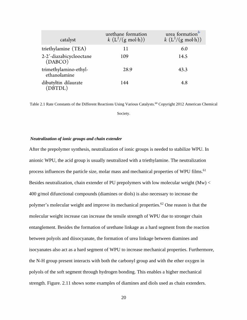
Catalyst
In the synthesis of WPU, the selection of catalyst is significant because different catalysts can
determine the rate of reaction of alcohols, giving urethane bonds or urea bonds (Table 2.1).
Metal complexes (bismuth, lead, zinc, tin and mercury) and amine compounds
(dimethylcyclohexylamine (DMCHA), dimethylethanolamine (DMEA)) are two types of
commonly used catalysts for the synthesis of WPU. Tin based catalysts strongly accelerate the
rate of urethane formation. Amine catalysts can drive either the urea, urethane or isocyanate
trimerization reactions. However, some amine and metal catalysts are toxic and removing
catalyst from WPU is difficult, which is a disadvantage in most applications.60
20
Table 2.1 Rate Constants of the Different Reactions Using Various Catalysts.60 Copyright 2012 American Chemical
Society.
Neutralization of ionic groups and chain extender
After the prepolymer synthesis, neutralization of ionic groups is needed to stabilize WPU. In
anionic WPU, the acid group is usually neutralized with a triethylamine. The neutralization
process influences the particle size, molar mass and mechanical properties of WPU films.61
Besides neutralization, chain extender of PU prepolymers with low molecular weight (Mw) <
400 g/mol difunctional compounds (diamines or diols) is also necessary to increase the
polymer’s molecular weight and improve its mechanical properties.62 One reason is that the
molecular weight increase can increase the tensile strength of WPU due to stronger chain
entanglement. Besides the formation of urethane linkage as a hard segment from the reaction
between polyols and diisocyanate, the formation of urea linkage between diamines and
isocyanates also act as a hard segment of WPU to increase mechanical properties. Furthermore,
the N-H group present interacts with both the carbonyl group and with the ether oxygen in
polyols of the soft segment through hydrogen bonding. This enables a higher mechanical
strength. Figure. 2.11 shows some examples of diamines and diols used as chain extenders.

21
Figure. 2.11 Examples of commonly used diol and diamine extenders.17 Copyright 2019 American Chemical
Society.
2.3.3.2 Emulsion
Water based polyurethane (WPU) can be regarded as an emulsion. An emulsion is defined as a
mixture of two immiscible liquid phases where one liquid is dispersed phase and the other is
continuous phase.63 In addition to containing the liquid, an emulsion may also contain solid
particles. For WPU, the dispersion of hydrophobic PU particles in water form a stable oil-in-
water emulsion. The formation of emulsion (emulsification) usually requires strong mechanical

22
energy such as shaking, stirring or ultrasonication to disperse one liquid into small droplets in
another continuous phase. However, the emulsions formed without surfactants would not be
stable and would separate into different layers. Surfactants increase the stability of emulsion by
decreasing interfacial tension and increasing interfacial viscosity. Two main mechanisms are
introduced which explain the stability of emulsion, including electrostatic repulsion and steric
repulsion.64 Electrostatic force occurs by adsorption of ionic surfactant on the surface of
particles, resulting in repulsion forces around the charged droplets which prevent droplet
contact.65 This mechanism is suitable for oil-in-water emulsions. In one example, the ionic
groups such as DMPA on WPU act as ionic surfactant to stabilize the emulsion. Steric repulsion
occurs by adsorption of non-ionic surfactant on the surface of water droplets. The long
hydrophobic tail can repulse these droplets, which is suitable for water-in-oil emulsions.66
2.4 Fabricating and Processing of PU composites
PU composites have been widely used as coatings, biosensors, solar cells, blood bags, adhesives,
elastomers and actuators due to their excellent flexibility, stretchability, durability,
biocompatibility and processability.67-70 Several methods for fabricating PU composites such as
printing, melting and blending are described.
Printing technologies have been extensively developed in both scientific research fields and
practical manufacturing applications due to the convenience, fast and cost-effectiveness. Printing
of PU composites depend on optimum solution (ink) viscosity, which is controlled by the
molecular weight of the PU and solution concentration. Lower molecular weights are generally
used to achieve a low viscosity and to minimize solvent problems including flammability,
toxicity, recovery, and cost. The ink is usually prepared by a solution mixing method where

23
nano- or micro- sized fillers are dispersed in the PU solution by stirring or sonication, with the
addition of surfactant to improve dispersion.71 Ink jet printing, screen printing and three-
dimensional (3D) printing are commonly used for fabricating and processing PU composites.
For ink jet printing, a fixed quantity of ink was filled into a chamber that is responsive to the
external voltage. Sudden volume reduction of the chamber caused by pluses of voltage induced
the ejection of liquid droplets from the nozzle. The ejected droplet falls on the substrate and then
dries with solvent evaporation (Figure 2.12a).72 WPU dispersion and composites ink are suitable
for inkjet printing since they are environmentally friendly and have the proper viscosity of a
water solvent. For example, van der Berg et al. printed layered 3D structures using an aqueous
40wt% WPU via a piezoelectric inkjet printer. The height of a printed individual drop and a
complete layer were 3µm and 10µm, respectively.73 Krober et al. fabricated PU microstructures
via reactive inkjet printing. Two inks containing IPDI and PPG from separate nozzles were
merged on substrate and polymerized in situ to form PU structures after 3 minutes of fast
curing.74
Screen printing is a simple, fast and low-cost processing method obtaining uniform deposition
manufacturing, which has been adopted by many researchers for printing nanocomposites.75,76
Zhang et al. utilized graphene-modified WPU paste screen printing to achieve inexpensive,
scalable manufacturing of graphene-reinforced polymer nanocomposites. A typical screen printer
consists of a nylon, polyester, silicon, or stainless-steel screen with a certain density and required
printing patterns. The mesh pores are closed in non-printing areas by a photo- polymerized resin,
while pores remaining in the printing pattern areas are left open to allow the paste to flow
through. A squeegee composed of polyurethane or rubber deflects the screen downwards to make
contact with the substrate, applying appropriate pressure. During printing, the paste is deposited

24
to produce the nanocomposite (Figure 2.12b).77 Yang et al. developed a pressure sensor
composed of a layer by layer structure of poly (vinylidene fluoride), silver nanowires,
thermoplastic polyurethane through screen printing and ultrasonic bonding.78
3D printing technology, known as additive manufacturing (AM), can create complex
topographical structures via layer by layer fabrication and have been used in a variety of
applications in biomedical, food, electronics and soft robotics industries. In contrast to other
printing technologies, 3D printing can create more complex geometries and multicompositions.79
Hung et al. synthesized a biodegradable WPU dispersion to fabricate nontoxic and highly elastic
scaffolds via 3D printing. 3D printing was made using a liquid-frozen deposition manufacturing
(LFDM) system (Figure 2.12c). In the system, the architectural design was generated using
computer-aide design (CAD) techniques and scaffolds with complex shapes such as a human ear
can be layer-by-layer fabricated using this method.80 Kim et al. fabricated a multiaxial force
sensor using fused deposition modeling (FDM) 3D printing. The structural and sensing part of
the sensor was printed with TPU filament carbon nanotube (CNT)/TPU nanocomposite filament,
respectively.81 Chen et al. prepared TPU/ poly(lactic acid) (PLA)/graphene oxide (GO)
nanocomposites via a solvent-based mixing process and extruded into filaments for fused
deposition modeling (FDM) 3D printing, showing a potential application as biocompatible
materials.82

25
Figure 2.12 (a) shows a common fluid tubular cavity geometry consisting of a glass tube with a nozzle and an orifice
at one end, and a connection to a supply tube, generally of larger diameter, at the other extreme.72 Copyright 2016
MDPI open access. (b) Schematic of a typical screen printer, comprising of a squeegee and screen mesh attached
onto a frame.77 Copyright 2019 The Royal Society of Chemistry. (c) 3D printing from aqueous dispersion and
schematics of the LFDM system for scaffold fabrication.80 Copyright 2014 WILEY‐VCH Verlag GmbH & Co.
KGaA, Weinheim.
Melting blending is commonly used to fabricate TPU composites due to good flowability above
melting temperature. Since some fillers are not soluble in common solvents, melting blending
can easily mix insoluble fillers into PU without using a harmful organic solvent.83 Single or twin-
screw extruders and internal mixer are instruments that are typically used for melting
processing.84 Injection molding was often combined with extruders to make samples with
specific shapes for further testing.85 Figure. 2.13 shows a schematic illustration of the reactive
extrusion setup consisting of dispensing units equipped with digital flow meters, gear pumps and
gas lines, extruder, water bath, drying unit, and pelletizer. The nanocellulose/TPU
nanocomposites were obtained after cooling and drying.86 Xue et al. incorporated TPU into
poly(ether-block-amide) (PEBA) via melting blending to improve the toughness of PEBA for
biomedical applications.87 Barick et al. fabricated polymer TPU/montmorillonite (OMMT)

26
nanocomposites by a melt intercalation technique using a laboratory internal batch mixer
followed by compression molding.88
Figure. 2.13. Schematic representation of reactive extrusion of polyol/nanocellulose dispersion with comonomers of
polyurethane. 86 Copyright 2016 Elsevier B.V.
Other methodologies are also employed to fabricate and process PU composites. Direct-writing
technology was used to fabricate PU/CNT nanocomposite microfibers directly on a silicon
substrate. Figure. 2.14a shows an illustration of the UV-direct writing fabrication technology for
fabricating the PU/CNT nanocomposite filament between two metallic Ti/Mo electrodes.89 Wet
spinning was employed to produce a stretchable and conductive composite fiber from surface
modified AgNWs and TPU. The spinning dope consists of a PU/AgNWs /DMF solution
extruded through a syringe needle into the water coagulation bath via a syringe pump. The
spinning dope was solidified via countercurrent diffusion of DMF and water in the coagulation
bath. The composite fiber was collected on a stainless spool and dried in air (Figure. 2.14b).90 In
situ polymerization was used to fabricate a conductive PPy/PU composite foam.91 Spray coating

27
was used to fabricate PU composites with a wide variety of patterns, shapes and sizes.92 Hao et
al. fabricated an abrasion resistant WPU/graphene/tourmaline fabric-based Joule heater with a
sandwich structure via spray coating, showing a fast electrothermal response, low operation
power, good flexibility and abrasive resistance.93
Figure. 2.14. (a) Schematic of the nanocomposite microfibers fabricated by the ultraviolet-assisted direct-write (UV-
DW) process directly on pre-patterned substrate.89 Copyright 2012 IOP Publishing Ltd. (b) Schematic illustration of
wet-spinning of composite fibers and photograph of AgNWs/PU composite fiber collected on a stainless-steel
spool.90 Copyright 2017 American Chemical Society.
2.5 Flexible and stretchable electronics
In recent years, PUs have been investigated for their potential application in flexible and
stretchable electronics due to their superior elasticity, stretchability and mechanical strength. In
the following section, the conduction mechanism and design strategies are presented; after that, a
few particular examples of PU flexible and stretchable electronics are discussed.

28
2.5.1 Electron conduction mechanism
2.5.1.1 Percolation theory
The percolation theory is commonly used to explain the mechanism of electron transferring in
conductive composites94. The percolation threshold is the concentration in which a continuous
connection of conductive fillers occurs. With the addition of conductive fillers to the polymer
matrix, the resistance of conductive composites slowly decreases until reaching the percolation
threshold. Before percolation, there is no concrete connection between fillers. After the
percolation threshold, resistance drops significantly.95 Based on the percolation theory, the
relation between the resistivity of conductive composites and filler content is shown in Figure.
2.15.
Figure. 2.15 Typical percolation curve for conductive composites based on the percolation theory.96 Copyright 2015
UWSpace.

29
According to the percolation theory, transportation of electrons occurs through electrical
pathways formed by conductive fillers. The conductivity of composites is mainly determined by
the volume fraction of fillers.
𝜎 = 𝜎0(𝑉𝑓 − 𝑉𝑐)𝑠 (1)
Where σ is the conductivity of composite, 𝜎0 is a scaling factor proportional to the conductivity
of filler, Vf is the volume fraction of filler, Vc is the percolation threshold, and s is the exponent
of conductivity. Percolation threshold depends on morphology of fillers (0D, 1D and 2D), which
will be discussed below.97
2.5.1.2 Nanoparticles (NPs) as fillers for stretchable electronics
In the conducting network of nanoparticle-based composites, it is assumed that all particles are
homogeneously dispersed in the polymer matrix without aggregation. The percolation threshold
(Vc) can be calculated by
𝑉𝑐 =𝜋𝐷3
6(𝐷 + 𝐷𝐼𝑃)3 (2)
where, D is particle diameter, and DIP is interparticle distance.98 Therefore, Vc increases as the
particle size increases. DIP can affect the tunneling current between nanoparticles. A large
distance leads to higher tunneling resistance and therefore lowers the conductivity of composites.
Electron hopping occurs when DIP is less than 10nm, resulting in higher conductivity of
composites. Therefore, 10nm of DIP is critical to achieve high electrical conductivity of
nanoparticle based stretchable composites.99 During stretching, the large strain sharply increases
the DIP. However, nanoparticles can reorganize along the stretching direction because they are
small enough to self-assemble at the phase boundary of the surrounding polymer chain by van

30
der waals and steric forces. This self-assembly and reorganization effect can retain structural and
electrical integrity of composites, which can be described by the following model:
𝑉𝑐(ɛ) =𝑉𝑐
0
1 + 𝑎√ɛ (3)
where 𝑉𝑐0and 𝑉𝑐(ɛ) is the percolation threshold under free standing and under strained condition,
respectively. 𝑎 is the reorganizing capability of nanoparticles under stretching, ɛ is strain.100
Besides using this unique property to maintain conductivity during stretching, some structure
design can further improve the stretchability of nanoparticle based stretchable electronics, which
is discussed later.
2.5.1.3 Nanowires (NWs) or Nanotubes (NTs) as fillers for stretchable electronics
NWs or NTs have a lower percolation threshold than NPs because of the anisotropic high aspect
ratio (10 to 100 times higher). Pike and Seager determined a critical length lc of wires at which
percolation would occur 101,
𝑙𝑐
√𝑁𝜋
2= 2.118 (4)
where N is the number of wires in the system. According to the excluded volume (area) theory:
𝑁𝑙𝑐2 = 𝑁𝑐𝑙2 (5)
Where Nc is percolation threshold density, l is the length of wires. Therefore, according to
equations (4) and (5):
𝑁𝑐𝑙2 = 5.71 (6)

31
The percolation threshold density (Nc) is inversely proportional to the square of filler length (l).
Combined with equation (1), assuming the conductivity is same, 1D NWs or NTs can
significantly decrease the filler density or volume, compared with 0D NPs. Therefore, NWs
provide less contact resistance and decrease the filler contact area, which has a smaller
conductivity drop during stretching. Additionally, NWs and NTs are suitable to achieve a
percolation network on the surface of materials to make transparent stretchable electronics.
2.5.1.4 Nanoflake or nanosheet as fillers for stretchable electronics
2D materials such as graphene or silver micro/nanoflakes can provide a larger junction area
compared with NPs or NWs, significantly decreasing the contact resistance and allowing more
electron tunneling. The total resistance of composites is the summation of individual sheet
resistance.98
1
𝑅𝑇= 𝑝2
1
𝑝1(𝑅𝑖,𝑖 + 𝑅𝑖,𝑖+1) (7)
Where RT is total resistance of composite, p1 is the number of nanosheets in conducting paths, p2
is the number of nanosheets in parallel conducting paths, Ri,i and Ri,i+1 is the summation of
intersheet resistance and intrasheet resistance. The intrasheet resistance is quite small due to the
high conductivity of the 2D material. The intersheet resistance (contact resistance) is critical to
the total conductivity of the composite, which can be calculated by102
𝑅𝑖,𝑖 = 𝑎𝑑0(ɛ + 1)𝑒𝑏𝑑(ɛ+1) (8)
Where d0 is the sheets distance at the unstretched state, d is the sheets distance under strain, ɛ is
applied strain, a and b are constant. Therefore, the volume fraction, morphology and overlapping
of nanosheets can affect the total conductivity of composites.

32
2.5.2 Strategies to design stretchable electronics
To achieve stretchable electronics, there are two main strategies: one is “structure that stretch”
and the other is “materials that stretch”. Common stretchable structures mostly include wavy
structure, percolating networks and serpentine interconnects103-105. Besides the special structures,
the stretchability of interconnection materials or electrodes can be achieved by combining
nanomaterials with an elastic polymer matrix. Nanomaterials include carbon nanotubes (CNTs),
graphene (Gr), conductive polymer, and their composites106-108.
2.5.2.1 Structure that stretch
With a specific structural layout, some rigid conventional conductive materials including Si, Cu,
and Ag will provide desirable performance. It is well known that any material in the ultrathin
format shows flexibility because bending strain decreases proportionally with thickness. Single
crystalline metal Si as an example, is brittle and rigid whereas the thin forms such as nanowires
or nanomembranes are flexible. To further achieve stretchability of these materials, wavy
structure, percolating networks and serpentine interconnects are the most effective strategies.
Wavy structure
To form the wavy structure, the pre-strain-release-buckling strategy is shown in Figure. 2.16,
which means depositing or coating brittle, inorganic materials to the pre-strained elastic polymer
substrate surface, followed by releasing the pre-strain103.

33
Figure. 2.16. Schematic illustrations of the wavy structure processes: (a) pre-strain–release–buckling and (b)
stretching–release–buckling109. Copyright 2015 WILEY‐VCH Verlag GmbH & Co. KGaA, Weinheim.
The typical example is silver nanowires (AgNWs) coated on a polydimethylsiloxane (PDMS)
surface. When strain is applied, the wavelengths and amplitudes of the wavy structure changes,
involving substantial strains in the PDMS instead of the AgNWs, which results in remarkable
stretchability. Another advantage of this method is that it achieves high optical transmittance and
high conductivity at the same time. The AgNWs-PDMS thin film has the sheet resistance (Rs)
ranging from 9 Ω sq−1 to 70 Ω sq−1 and a transmittance (T) at a wavelength of 550 nm from 90%
to 96%. (Figure. 2.17)

34
Figure. 2.17. (a) Optical image of stretchable AgNWs/PDMS thin film; (b) microscopic “wavy” structure of AgNWs
on PDMS substrate; (c) Optical microscopy image, and (d) scanning electron microscopy image of a wavy
substrate110. Copyright 2007 American Chemical Society.
Percolating networks
Different from the wavy structure fabricated by depositing metal nanowires on the surface of the
elastic substrate, using percolating networks of metal nanowires via randomly embedding metal
nanowires beneath the surface of the cured elastic substrate can also achieve high
stretchability111,112. The fabrication process reported in these works is shown in Figure. 2.18.
First, AgNWs is drop casted onto a glass substrate to form a uniform coating. Then, PDMS is
coated on the layer of AgNWs followed by curing. Finally, the AgNWs-PDMS film is peeled off
to finish the AgNWs transfer from glass to PDMS. The stretchability of the material based on
percolating networks depends on the capacity of the entangled metal nanowires in response to
applied strain; whereas the stretchability of wavy structured material shows a high dependence
on the pre-strain; that is the larger the pre-strain, the higher the stretchability. Therefore, the

35
stretchability of the percolating network is inferior to the wavy structure. However, the
conductive layer adhesion to the substrate of percolating networks is much stronger than the
wavy structure, which can undergo a large number of stretching cycles. Also, the surface
roughness of the material based on percolating networks is extremely small, which is suitable for
flexible displays and optoelectronics.
Figure. 2.18. (a) Schematic illustration of the fabrication process of percolating networks of AgNWs in PDMS. (b)
Scanning electron microscopy image of the AgNWs percolating network; (c) Optical image of the
AgNWs/PDMS111. Copyright 2014 The Royal Society of Chemistry.
Serpentine interconnects
A special two-dimensional spring-like structure with a specific amplitude-wavelength ratio can
be designed for metal nanowires before embedding them into polymer matrix. The stretchability

36
of serpentine interconnects is related to the amplitude-wavelength ratio, the larger the amplitude-
wavelength ratio, the higher the stretchability. When a strain is applied, the wavelength elongates
and the amplitude shrinks instead of the metal nanowires changing, resulting the stretchability
being higher than that of percolating networks. In Figure. 2.19, Au nanowires with a different
amplitude-wavelength ratio is directly embedded beneath the PDMS surface, which can lighten a
LED without strain and also maintain the luminescence when the strain is 25%104.
Figure. 2.19. (a) Images of the original structure of serpentine gold nanowires bonded to the elastomer (left) and the
stretched structure (right). (b) Optical microscopy images of serpentine gold nanowires with different amplitude–
wavelength ratios; (c) Optical image of a circuit composed of a thin-film electrode without strain, a power source,
and a LED (left) and the circuit after stretching (right)104. Copyright 2004 WILEY‐VCH Verlag GmbH & Co.
KGaA, Weinheim.

37
2.5.2.2 Materials that stretch
Different from metals, some nanomaterials including carbon nanotubes (CNTs), graphene (Gr),
conductive polymer, and their composites are intrinsically flexible and stretchable. These
nanomaterials can be dissolved or dispersed in solvents with an elastic matrix by a fairly simple
and low-cost method, compared to the complicated structural layouts involving multiple steps.
Therefore, the combination of these nanomaterials with flexible polymer matrix can fabricate
highly stretchable interconnection materials.
Among these nanomaterials, conductive polymers based on polyanilines, polypyrroles and
polythiophenes have attracted the most attention. The conductivity arises from electron transfer
along the conjugated π-molecular backbone dopant with the motion of charge carriers.
Polyaniline can form processable conductive forms at a low cost and in large amounts. However,
toxic benzidine moieties in the polymer chain limit their applications. Polypyrroles and
polythiophenes are nontoxic, conductive with a dopant, and have good adhesion with different
substrates. For example, many flexible electrode, sensor and energy storage devices based on
PPy were well developed112-114. Poly(3,4-ethylenedioxythiophene): Poly(styrene sulfonate)
(PEDOT:PSS) is a core-shell structured conductive polymer with high mechanical flexibility and
excellent dispersion abilities in water115, which have been widely used in solar cells, capacitors,
transistors and other devices that require electrical conductive films to function116–118.
PEDOT:PSS has a gel-like coil structure in water with a diameter ranging from 10 nm to 50 nm;
it has been called PEDOT:PSS nano-gels, which are quite stable in aqueous solutions at room
temperature119. Many researchers utilize PEDOT:PSS aqueous dispersion to make thin film120,
conductive polymer inkjet droplets121,122 and actuators.

38
However, the main shortage of these carbon materials and conductive polymers is the
conductivity, which is at least three orders of magnitude lower than that of metal materials.
Figure. 2.20 shows the change of conductivity as a function of the applied strain of different
materials. An obvious trend is that the metal filled composites have significantly higher
conductivity than carbon materials, whereas the CNT filled composites can maintain their initial
conductivity at a larger strain123.
Figure. 2.20. Comparison of conductivity change of the metal-based and carbon-based material as a function of
tensile strain123. Copyright 2014 WILEY‐VCH Verlag GmbH & Co. KGaA, Weinheim.
To increase the conductivity of carbon materials and conductive polymer filled composites,
combining at least two different materials, such as Ag-CNTs, AgNWs-Graphene and AgNWs-
CNTs, can compensate for the disadvantages of each material and create great, high potential in
stretchable electronics. This idea is quite similar to the hybrid epoxy-based ECA system. Figure.
2.21 shows the hybrid Ag flake and CNTs system, which has a high conductivity and

39
stretchability. The high intrinsically conductive silver flake provides a large number of
conductive routes and prevents the intrinsically flexible CNTs from separation under stretching.
The Ag-CNTs material has initial conductivity of 5700 S/cm and 20 S/cm at 140% strain, which
can easily lighten a LED 124.
Figure. 2.21. The cartoon of Ag-MWNT film. b) Optical images of LEDs at an applied bias of 3.3 V before (top)
and after (bottom) stretching. The current decreased to 71.7% at 30% strain and returned to the original value after
the release124. Copyright 2010, Springer Nature.
2.5.3 PUs application in flexible and stretchable electronics
PU has been widely studied in the fields of flexible and stretchable electronics by researchers.
Several examples will be provided in this section (Figure. 2.22). Zhang et al. constructed a three-
dimensional interpenetrating alignment configuration of conductive carbon fibers during PU tube
extrusion by manipulating opposite-helical flows. The obtained PU tube showed high initial
conductivity, electrical stability under large strain and electrical reversibility in cycle loadings.125
Yang et al. fabricated highly conductive (<10 Ω/sq even under 100%) and stretchable PU/silver
nanowire composite electrodes based on a high-intensity pulsed light technique.126 Kim et al.
demonstrated stretchable conductors made by polyurethane and gold spherical nanoparticles via
layer-by-layer assembly and vacuum-assisted flocculation, showing high conductivity and

40
stretchability despite the minimal aspect ratio of the nanoparticles.127 Liu et al. developed
stretchable lithium-ion batteries with a sticky and porous PU/poly(vinylidene fluoride)
membrane as a separator, displaying good electrochemical performances and long-term stability
under release–stretch cycles.128 Tang et al. demonstrated a stretchable and conformable
memristor with fundamental synaptic functions based on a highly elastic silver nanoparticle-
doped TPU and polydimethylsiloxane (PDMS), which can be well operated at 60% strain and
conformed onto curved surfaces.129 Chen et al. demonstrated an ultrathin stretchable triboelectric
nanogenerator using electrospun PU nanofibers, carbon nanotubes and silver nanowires for
harvesting diverse biomechanical energies and acting as a self-powered gesture sensor.130 Wang
et al. reported a reliable, stretchable, and conductive composite yarn by incorporating single-wall
carbon nanotubes into the elastic cotton/(PU) core-spun yarn. The yarn can detect and monitor
the movement of human limbs such as fingers and elbows, and the wink of eyes.131 Ma et al.
reported highly conductive stretchable fibers synthesized by the scalable wet spinning process
using flower-shaped silver nanoparticles with nanodisc-shaped petals (Ag nanoflowers) and
polyurethane, showing extraordinarily high conductivity (41245 S/cm), stretchability, and
mechanical strength.132

41
Figure. 2.22 (a) The digital photograph and SEM images of the prepared composite tube.125 Copyright 2018 Elsevier
Ltd. (b) Photographs of a free-standing PU/gold nanoparticle film.127 Copyright 2013, Springer Nature. (c) Digital
photographs of the wavy battery powering a light-emitting diode at released and stretchable state at 50% strain.128
Copyright 2017 WILEY‐VCH Verlag GmbH & Co. KGaA, Weinheim. (d) SEM and 3D optical microscopy images
of stretchable and conformable memristor. Photographs of the memristor attached onto the cerebral cortex. Scale
bar: 1 mm 129 Copyright 2018 The Royal Society of Chemistry. (e) Photograph of stretchable triboelectric
nanogenerator.130 Copyright 2017 The Royal Society of Chemistry. (f) Schematics illustration and pictures of PU
yarns before and after stretching.131 Copyright 2016 American Chemical Society. (g) Digital photograph and SEM
images of conductive stretchable Ag-PU fiber.132 Copyright 2015 American Chemical Society.

42
2.6 Self-healing materials and electronics
2.6.1 Mechanism of self-healing
Flexible and stretchable electronics are subject to abrasion, wear, tear and can propagate cracks
over time during frequent use or transport, leading to unexpected damage of materials and
devices. To solve these problems, self-healing materials have been extensively investigated in
recent years. Self-healing materials can be divided into two classes: extrinsic and intrinsic.133
Extrinsic self-healing materials rely on external healing agents encapsulated in capsules or
vascular network to heal themselves. The damage lead to capsules or vascular networks break
and release the healing chemicals, to heal the bulk materials. White et al. incorporated a
microencapsulated healing agent - dicyclopentadiene (DCPD) monomer in bulk material.134 The
damage of material releases the monomer into the crack’s place via capillary action; and further
reacts with an embedded Ruthenium-based Grubbs’ catalyst to heal the damage. Compared with
the extrinsic self-healing materials, intrinsic self-healing materials are more durable and do not
need an external healing agent, thus they can repeatedly heal themselves.
The mechanisms of intrinsic self-healing materials are classified into two categories: reversible
covalent bonds and supramolecular chemistry.135 The advantage of reversible covalent bonds is
that they have high bonding strength which can enhance the toughness of materials. Reversible
Diels–Alder (DA) reactions are one of the dynamic reactions that have been extensively
investigated. The typical DA reaction uses furan (diene) and malemide (dienophile) entities to
build a crosslinked network.136 The elevated temperatures cause the disconnection of diene and
dienophile, and decreased temperatures rebuild the covalent bonds to heal the material. However,
high activation energy (above 100oC) is not suitable for some specific applications such as
electronics. Ideally, bond dissociation and reformation should occur at room temperature. Room

43
temperature reversible DA reactions were developed via the reaction of 6,6’-substituted fulvenes
and dicyano- and tricyano- ethylene carboxyesters under ambient conditions at 25oC.137Another
type of important, reversible covalent bonds are Disulfide bonds, where two neighboring S-S
bonds can undergo metathesis exchange reactions to break and reform via free radical or ionic
intermediate interactions138,139 by light, heat, or oxidation.140
Although materials show high mechanical strength with healed reversible covalent bonds, the
time required (several hours to several days) and low efficiency are the main drawbacks of this
mechanism. In contrast to reversible covalent bonding, weaker supramolecular physical bonds
can dissociate, and regenerate easily and can be remodeled rapidly and reversibly from fluid-like
to solid-like states. Therefore, they exhibit good reversibility and have a fast healing speed and
sensitivity. Supramolecular interactions contain hydrogen bonds, metal-ligand coordination,
ionic interactions, π- π stacking and host-guest interactions.5 For example, a wide range of self-
healing materials with diverse mechanical properties ranging from hydrogel to rubber are
prepared via Hydrogen bonds. A polymer containing H-bonding motifs including amidoethyl
imidazolidone, di(amidoethyl) urea, and diamido tetraethyltriurea is developed, which behaves
like a soft rubber at temperatures up to 90 oC, and can self-heal at ambient conditions.141
2.6.2 PU application in self-healing materials and electronics
PUs have been extensively developed as self-healing materials via a variety of mechanisms due
to its versatile chemical design, superior mechanical properties and self-healing abilities (Figure.
2.23). For example, Feula et al reported a healable and shape recovery supramolecular
polyurethane via π−π stacking and hydrogen bonding interactions, plus phase separation. The
material can heal at 45°C in 15 min with healing efficiencies over 99%.142 Chang et al. reported a
transparent, stretchable, self-healing polyurethane based on disulfide bonds, showing 90%

44
healing efficiency and 800% breaking elongation at a moderate healing temperature.143 Kim et
al. synthesized polyurethane end capped with propylamine with high contents of urea and
urethane groups, showing more than 96% self-healing efficiency via hydrogen bonding at
evaluated temperature.144 Ji et al. developed a self-healing diselenide-containing polyurethane
elastomer by controlling the ratios of diselenide bonds and the soft chain. The materials can be
healed under merely visible light with almost 100% self-healing efficiency.145 Wittmer et al.
synthesised a polyurethane urea polymer with implemented 1-(2-ami- noethyl) imidazolidone
(UDETA) moieties that shows a moisture triggered self-healing ability via hydrogen bonding.146
Chen et. al reported a self-healing polyurethane (urea) elastomer based on intrinsic dynamic van
der Waals forces and hydrogen bonding at different temperatures.147 Lai et al. developed
polyurethane elastomers with disulfide bonds, which exhibit colorless, superior transparency, a
maximum tensile stress of 25 MPa and a breaking elongation over 1600%.148 Yua et al. reported
a chemical design of supramolecular polymer materials consisting of soft polymeric chains
(polytetramethylene glycol and tetraethylene glycol) and strong and reversible quadruple H-
bonding cross-linkers. The material shows up to 17 000% breaking elongation, high toughness
(fracture energy ∼30 000 J/m2), and self-healing ability, which can further be used as an
electrode both in vivo and in vitro to measure electromyography signals.149 Kim et al. developed
a transparent and self-healing TPU at room temperature via aromatic disulfide metathesis,
showing high tensile strength and toughness (6.8 MPa and 26.9 MJ m−3), stretchability (900%),
self-healing efficiency (over 80%).150

45
Figure. 2.23 (a) Healing PU elastomer using 457 nm blue laser as light source. The laser source was 3.5 m away
from the sample to be healed. The circle indicated the position of the sample and the dashed line indicated the path
of laser.145 Copyright 2015 WILEY‐VCH Verlag GmbH & Co. KGaA, Weinheim. (b) PU elastomer healed via
hydrogen bond and van der Waals force.147 Copyright 2019 The Royal Society of Chemistry. (c) The multiphase
design and mechanism of tougher and more robust self-healing thermoplastic elastomers.148 Copyright 2018
WILEY‐VCH Verlag GmbH & Co. KGaA, Weinheim. (d) Schematic illustration and digital photograph of the
design of stretchable supramolecular polymeric materials.149 Copyright 2018 American Chemical Society. (e) TPU
film cut in half, respliced, and healed for 2 h (+4 h) at 25 °C, followed by a 5 kg dumbbell lifting test.150 Copyright
2018 WILEY‐VCH Verlag GmbH & Co. KGaA, Weinheim.
2.7 Mechanoresponsive Smart Windows
Due to their superior optical transparency, high stretchability, high mechanical strength and easy
processability, PUs have potential for fabricating mechanoresponsive smart windows. Smart

46
windows, including electro-, thermo-, mechano- and photochromic, are a type of intelligent
structure capable of dynamically switching their transparency, which have attracted extensive
research interests due to their wide range of applications in energy saving buildings,151 flexible
solar cells,152 and wearable biosensors.153 To date, myriads of stimuli-responsive materials
ranging from rigid to soft including metal oxides,154 polymer dispersed liquid crystals
(PDLCs),155 and polymeric nanocomposites156, have been explored for devising smart windows.
Compared with already commercialized electro-, thermo- and photochromic smart windows,
mechano-responsive smart windows recently emerged and possess the greatest potential for real
applications because of their low cost, simple fabrication and energy efficiency.
The working mechanism of mechanoresponsive smart windows is straightforward: mechanical
strain induces the change of surface morphology or microstructure on the material, resulting in
the change of optical transparency of material via light scattering or diffraction. Surface wrinkles
and polymeric nanocomposites are common approaches for the design and fabrication of
mechanoresponsive smart windows.6
2.7.1 Wrinkle based mechanoresponsive smart windows
The dynamic tunable wrinkle is a promising candidate for constructing mechanoresponsive smart
windows. The wrinkle based mechanoresponsive smart windows usually consist of bilayers, a
substrate layer and a film (wrinkled) layer. Both layers at the unwrinkled state are transparent.
After making wrinkles on the substrate layer, the patterned surface wrinkles have periodicity or
wavelength in the sub-micrometer range, which can reflect and scatter visible light and result in
the decrease of optical transmittance of the bilayer system. The opaque bilayer system is the
initial state of mechanoresponsive smart windows. After stretching, the wrinkles become flat and
the mechanoresponsive smart windows turn transparent. For example, a pre-stretched PDMS

47
surface is first treated by an oxygen-plasma to form a hydrophilic surface. Then, a PVA aqueous
solution is coated on the pre-stretched PDMS surface to form a bilayer film. After realising the
pre-strain, the PVA/PDMS bilayer film is opaque, to form a mechanoresponsive smart window
(Figure 2.24).157
Figure 2.24 (a) Schematic illustration of the fabrication process of surface wrinkles on the bilayer film. (b-d) Bright-
field optical microscope images of the surface wrinkles on top (b-c) and cross-section (d). (e) A large size
PVA/PDMS bilayer film with surface wrinkles for smart windows.157 Copyright 2018 WILEY‐VCH Verlag GmbH
& Co. KGaA, Weinheim.
2.7.2 Polymeric nanocomposites based mechanoresponsive smart windows
Creating SiO2 nanoparticle embedded PDMS composites is another promising approach for
constructing mechanoresponsive smart windows. A thin layer of a quasi-amorphous array of
silica NPs were spray coated on a flat substrate, followed by pouring PDMS precursors on silica

48
NPs arrays and curing. This strategy relies on the very similar refractive index and different
mechanical properties of silica NPs and PDMS film. The obtained smart window is initially
transparent due to the similar refractive index of silica NPs and PDMS. Upon stretching, the soft
PDMS deforms immediately while rigid silica NPs do not, leading to air voids generated around
the silica NPs array. These voids create a new interface between silica and PDMS (silica/void
and PDMS/void), which significantly increases the refractive index and results in the decrease of
transmittance (Figure 2.25). 158
Figure 2.25 (a) Schematic of the smart window fabrication process. (b) Schematic illustration of the void formation
around the silica particles when stretched. The arrows indicate PDMS ligaments. (c) Digital photographs of a
silica/PDMS film consisting of nanoparticles of diameter 258 nm at various strains.158 Copyright 2015 WILEY‐
VCH Verlag GmbH & Co. KGaA, Weinheim.

49
Chapter 3. Water Based Polyurethane Conductive Ink
for Stretchable E-textile Application
Introduction
In recent years, the function of clothing is not only making people warm and comfortable, but
also exhibits additional electronic features. The concept of clothing is undergoing a transition
from traditional textile to electronic textile (E-textile). E-textiles are ideal components for
wearable electronics due to their ability to sense and respond to environmental stimuli.159 For
example, many researchers incorporate solar cells, thermoelectric or piezoelectric devices into
textiles to generate electricity. Also, fabricating lithium ion batteries and supercapacitors into
textiles that can store electricity. Besides, there are many textile sensors such as biosensors for
electrocardiogram,160 electromyography,161 and electroencephalography162 sensing; and
temperature sensors which incorporate thermocouples into textile.163
Fabrication of conductive E-textile is important to achieve functional and wearable E-textile
electronics. Three types of materials are usually explored to fabricate conductive E-textiles,
namely conductive polymer-based E-textile, carbon-based E-textile and metal-based E-textile.164
Firstly, conductive polymers such as poly (3,4-ethylenedioxythiophene) polystyrene sulfonate
(PEDOT:PSS) and polypyrrole (PPy) are promising materials because of their unique electrical,
optical, and mechanical properties.165,166 For example, Ail et al. deposited PPY on yarn to make a
E-textile artificial muscle.167 Ding et al. reported the preparation of PEDOT:PSS coated
conductive fabrics using the dip coating method, where the fabric conductivity reached up to 2
S/cm after multiple soaking steps.168 Secondly, carbon-based materials including carbon
nanotubes (CNTs), carbon fibers and graphene exhibit extraordinary properties such as their light

50
weight, high mechanical strength, and superior electrical conductivity.169,170 Hu et al. prepared
CNT-cotton yarns showing high electrical conductivity (125 S/cm) with outstanding
stretchability and flexibility.171 Thirdly, metallic materials are considered to be better materials
for wearable electronics due to their high conductivity, which are usually three magnitudes
higher than conductive polymer and carbon based material.172,173 Cui et al. prepared a silver
nanowire based textile by simply dipping textile in a silver nanowire ethanol dispersion, which
had a textile conductivity of 2127 S/cm.174
Conductive polymers play a crucial role in E-textile for the development of medical textiles,
stretchable heaters, flexible textile keyboards, biosensor, etc.175,176 Among the group of
conductive polymers including polyaniline (PANI), polypyrrole (PPy) and poly(3,4-
ethylenedioxythiophene) polystyrene sulfonate (PEDOT:PSS), PPy has unique advantages for E-
textile due to superior biocompatibility, long term stability and non-toxicity.12 However, the
black PPy particles can not be dispersed in neither water nor most organic solvents, which
hinders their application in textile.13 So far, almost all PPy based E-textiles are made by direct in-
situ polymerization on textile using chemical or electrochemical methods.14,3 The main shortages
of the in-situ method are the weak adhesion between PPy and textile, discontinuous conductivity
of E-textile during stretching due to spherical morphology of PPy; and difficultly in large
manufacturing. Here, we synthesize water dispersible PPy nanowires which are several
micrometers long and could maintain stable conductivity during stretching. In addition, by
combining the water dispersible PPy nanowires with water-based polyurethane, the adhesion
between PPy and textile significantly increases. Furthermore, this non-toxic aqueous based PPy-
Polyurethane ink can easily be coated or printed on textile, which is promising for simple,
inexpensive and large-scale manufacturing.

51
The above-mentioned materials present good conductivity, flexibility and stretchability.
However, they lack durability and washability. Most of them suffer from their poor adhesion
onto the textile and dried inks are prone to be wiped off and washed away. Therefore, polymer
binder is significant and important for E-textile, to enhance the adhesion between conductive ink
and textile for practical applications.177 However, adding polymer binder into textile could cause
a loss in the conductivity and stretchability of the E-textile because of the porous and deformable
textile structure. The textile consists of numerous individual fibers and these individual fibers
form fiber bundles. The cured conductive ink on top of the textile could stiffen the textile by
binding the fiber bundles, subsequently disturbing movement of fibers in textiles.178 Also, the
cured ink could crack on the top of textile. To avoid the cracking of cured ink and stiffening of
the textile, the ink should be coated only on the individual textile fibers, instead of coating whole
fiber bundles together. To achieve this, low viscosity inks can meet the requirement, however,
they will sacrifice conductivity due to their low solid content of the ink. High viscosity inks
cannot penetrate well into porous textile structures even though they easily stay on the textile
surface, they make ink crack and as a result the textile loses stretchability and conductivity after
stretching.
Polyurethane has wide applications in adhesives, coatings and elastomers in textile. The
advantages of using polyurethane in textile include the improvement of breaking strength,
waterproof ability, flexibility and durability.179,180 Aqueous polyurethane can be formulated for
adhesives and coatings with eco-friendly, no volatile organic compound (VOC) solvents,
nontoxic and non-flammable properties.34 Some works have been reported to use aqueous
polyurethane as a coating for textile. For example, Molla et al. developed an aqueous UV-

52
curable acrylate polyurethane as a binder for all types of fabrics using pigment dyes.181 George et
al. used hydrophilic poly (ethylene oxide) polyurethanes as a breathable coating for textile.182
Here, we report our recent development of an aqueous-based conductive ink with silver and PPy
as fillers, respectively, which can penetrate into textile effectively and obtain high conductivity,
high stretchability and high durability. This ink is based on a highly stretchable water-based
polyurethane as binder, which is free of harmful organic solvents and cures fast in 10 mins at
60oC. After applied to fabrics, the sheet resistance of E-textile is initially 0.016 Ω sq-1 without
stretching for silver-based textile. The sheet resistance increases 8.3 times after 30% strain and
38 times after 70% strain. The ink-coated textile can maintain high conductivity after 10 times of
a stretch cycle under 70% strain and 20 times of a wash cycle. Finally, a strain E-textile sensor
on the human body shows its potential application for tracking movement.
Experimental Section
Materials
Silver microflake (density of 10.49 g/cm3, particle size between 1 μm and 10 μm) and Pyrrole
(98%) were purchased from Sigma-Aldrich and used as the principle conductive filler for the
ink. Water-based polyurethane (UD-303) was purchased from Bond Polymer International and
used as polymer binder. Trimethylolpropane tris (2-methyl-1-aziridine propionate) (PZ-28) was
purchased from PolyAziridine LLC as the curing agent for polyurethane. Textile (80% nylon
20% spandex) was purchased from Fabricland.
Fabrication of Stretchable Conductive E-textile
Water-based polyurethane and PZ-28 curing agent were mixed with a weight ratio of 49:1 at
2000 RPM for 5 mins and degassed for 1min using ARE-310 Thinky Mixer (USA). After that,

53
silver flakes were added into the solution with a weight percent of 60% and then mixed at
2000RPM for another 5 mins. 10% weight percent water was used as solvent to adjust the
viscosity of the ink. After that, the mixture was coated onto a piece of pre-cleaned 6 cm x 1.5 cm
x 0.02 cm (length x width x height) textile. Finally, the textile was placed into an oven to be
heated at 60 °C for 10 mins to cure.
Synthesis of water dispersed PPy nanowire and WPU-PPy conductive ink
In a typical experiment, 0.3 mmol cetyltrimethylammounium bromide (CTAB) was dissolved in
30 ml 1M HCl followed by 30 mins sonication to form a homogeneous solution. 55 µl pyrrole
monomer was then added to the above surfactant solution followed by 10mins sonication and then
cooled down to 8oC. Precooled ammonium persulfate (APS)/HCL solution (275 mg/5 ml) was
added to the DA/Py surfactant solution dropwise under vigorous stirring at 8oC. The final mixture
was kept at 4oC for 24 hours. At the end of the reaction, the mixture was purified with a 0.4 µm
pore size filtration membrane and then washed with deionized water several times. The purified
PPy water solution was condensed to 20 ml. 500 mg SDS was added to the 20 ml PPy solution
followed by ultrasonication for 2 mins. 0.1 ml water-based PU and 1 ml PPy-SDS solution were
mixed together as an ink for textile coating.
Characterization Methods
Scanning Electron Microscope (SEM) (ZEISS Ultra 1530) was used for characterizing the
morphology of PPy and conductive E-textile. The electrical sheet-resistance of the E-textile was
measured using a four-point probe setup that includes a probe fixture (Cascade Microtech Inc.)
and a micro-ohm meter (Keithley 2440 5A Source Meter, Keithley Instruments Inc.). An infrared
camera was used to measure the temperature on the textile under voltage. Viscometer

54
(CAP2000+ Brookfield) was used to measure the viscosity of PU/PMANa colloid at 20 rpm at
room temperature.
Results and Discussion
WPU-silver textiles
The stretchable conductive ink is comprised of a water-based polyurethane binder, PZ-28 curing
agent, and silver flakes with a particle size of (1-10) µm as shown in Figure. 3.1a. The
polyurethane provides softness and stretchability to the ink and was chosen because it is free of
organic solvents, has a fast curing time at low temperature (10 mins at 60 oC), is durable and
stabile. This polyurethane dispersion is functionalized by the carboxylic group which can react
with polyfunctional aziridine crosslinker. The structure of PZ-28 is shown in Figure. 3.1b. The
reaction mechanism is shown as below in Figure. 3.1c. The aziridine end groups can react with
active hydrogen as found on carboxyl groups of polyurethane dispersions. Silver flakes being
conductive can provide a high conductivity at a low percolation value compared with silver
nanoparticles, which is shown in Figure. 3.1d.

55
Figure. 3.1. (a) Optical image of conductive ink. (b) Chemical structure of curing agent of polyurethane. (c)
Crosslink reaction mechanism of polyurethane. (d) SEM image of silver flakes.
The prepared conductive ink was coated on a piece of pre-cleaned 6 cm x 1.5 cm x 0.02 cm
(length x width x height) textile. The used textile is made of 80% nylon and 20% spandex, which
is commonly used for underwear and sportswear because of its excellent stretchability, up to ≈
250% strain and has good original length recovery under 70% strain. The prepared ink is
absorbed from the surface to the inside of textile by a capillary process after coating on textile.
The coated textile is dried at 60 °C for 10 mins. By printing the silver polyurethane ink on the
textile, the ink penetrates deeply into the back-layer textile and is immobilized inside of the fiber
bundles as the ink dries. Consequently, the stretchable ink form intrinsically stretchable
conductive paths inside of fiber bundles. The SEM images of the surface structure of the textile
at different resolutions are shown in Figure. 3.2a-d.
The textile is made of twisted fiber bundles and each fiber bundle consists of numerous
individual fibers (Figure. 3.2a). The gap between fibers is less than 10 µm, which is filled with

56
stretchable conductive ink, and the ink could penetrate through small gaps to make the textile
conductive (Figure. 3.2d). When the textile is covered by inks, the vacancies between fiber
bundles are not filled with the ink. This is because the transportation and penetration of ink fluid
only happens in fiber bundles (Figure. 3.2b-c). Therefore, these periodical fiber bundles are still
mobilized, maintaining the soft and stretchable properties of textile. Meanwhile, polyurethane
binder makes individual fibers compact with each other, which decreases the gap between fibers,
to achieve high conductivity of textile. The viscosity of the ink was 1500 cp at 20 RMP shear
rate at room temperature, which is suitable for good penetration into textile. The ink with higher
viscosity (more than 5000cp) could impede the penetration, leading to the aggregation on the
surface of textile. The ink with lower viscosity (400cp) could over-penetrate, leading to the
dripping and leaking of ink from textile. Therefore, the ink with proper viscosity can enable good
penetration, conductivity and stretchablity of textile.
Figure. 3.2. SEM surface images of conductive ink coated E-textile: (a) fiber bundles of E-textile. (b) Vacancies
between fiber bundles. (c-d) Silver flake-polyurethane ink coated on fiber bundles at different magnification.

57
To investigate the conductivity of knitted textile, the ink containing 60wt% silver flake is
selected to coat on 6 cm x 1.5 cm x 0.02 cm (length x width x height) textile. The sheet
resistance is initially 0.016 Ω sq-1 and 0.011 Ω sq-1 for 120 mg ink coating and 240 mg ink
coating, respectively. Because the solid content of PU was 30%, the loading density of ink with
solid mass were 345mg/cm2 and 917mg/cm2 for 120 mg ink coating and 240 mg ink coating,
respectively. The sheet resistance of 240 mg ink coated textile is only 0.005 Ω sq-1 lower once
coated, which means the textile is already saturated after coating once. The optical image shows
the ink penetrated deeply to the back layer of textile after one coating. (Figure. 3.3a). The sheet
resistance of E-textile is measured using a four-point probe as shown in Figure. 3b. To test the
piezoresistive effect, we stretched the textile along the fiber twisted direction. If the stretching
force was perpendicular to the fiber twisted direction, the deformation of textile can not be
recovered. The initial length of E-textile is 3 cm (Figure. 3c); after 250% maximum strain, the
initial length cannot be fully recovered and changes to 3.9 cm because of the deformation of
textile (Figure. 3.3d).

58
Figure. 3.3. Optical image of conductive E-textile and equipment set up. (a) Top layer and bottom layer of E-textile.
(b) Resistance measurement for E-textile by four-point probe. (c) Initial length of E-textile before strain. (d)
Recovered initial length of E-textile after 250% strain.
However, coating more material makes the textile stiffer and difficult to stretch because more ink
fills the big gaps between fiber bundles and decreases the textile mobility. The resistance of 240
mg ink coated textile decreases faster than 120 mg ink coated material. When strain is beyond
10%, 120mg ink coated textile is more conductive (Figure. 3.4). When strain is 30%, the
resistance increased 8 times and 33 times for 120 mg ink and 240 mg ink coated textile,
respectively. The conductive ink cracks at 170% for textile coated twice and at 250% for textile
coated once. Fiber bundles of textile initially curve and straighten when stress is applied. The
conductive ink fills the small gaps between individual fibers without filling the big gaps between
fiber bundles. This is why the textile can maintain conductivity after 240% strain. What’s more,

59
the ink fills part of the big gaps between fiber bundles of 240 mg ink coated textile, which makes
textile stiff and difficult to move, and as a result, crack early at 170%.
Figure 3.4. Sheet resistance of E-textile with different coating times at different strain.
The conductivity of textile can be partly recovered after the ink cracks. The resistance-strain
cycles are measured after the textile is stretched to 250% and recovered for 2 mins as shown in
Figure. 3.5. After the textile reaches the maximum strain, it can only recover to 3.9 cm compared
with the 3 cm original length, which is equal to a 30% strain state of initial textile. The initial
sheet resistance increases 500 times after 1 cycle and 518 times after 2 cycles. The textile loses
conductivity after 130% strain. This means some of the ink on the fibers crack at 250% and

60
cannot connect with each other after recovery. Therefore, the resistance obviously increases after
1 stretching cycle. In order to detect whether the conductivity of textile can be recovered at low
strain, the similar resistance-strain cycles are measured after the textile is stretched to 70% and
recovered for 2 mins as shown in Figure. 3.6. Compared with the maximum 250% strain, the
initial resistance almost stays the same after 10 strain cycles at maximum 70% strain, showing a
stable conductivity recovery property. This stable property as a strain sensor can be utilized to
measure body movement, where the strain is usually under 50%.
Figure. 3.5. Sheet resistance-strain cycles after 250% strain

61
Figure. 3.6. Sheet resistance-strain cycles after 70% strain
Besides the low resistance, this conductive textile also shows excellent cyclic durability as
shown in Figure. 3.7. Washability testing of the textile is conducted by repeating 20 wash cycles
in water for 30 mins and drying at 60oC for 10 mins. The resistance of both the 120 mg ink
coated textile and the 240 mg ink coated textile remain unchanged after 20 wash cycles. This
superior durability is provided by soft polyurethane binder in which the amine group of nylon is
strongly combined with polyurethane, and subsequently the durability of this conductive ink is
much higher than those without binder.10,13

62
Figure. 3.7. Initial sheet resistance at zero strain of E-textile at different wash cycles.
A strain sensor is developed by attaching a piece of E-textile onto a rubber glove to detect the
bending movement of fingers, as shown in Figure. 3.8a-c. When the demonstrator’s finger is
folded from 0 to 90 degrees, the resistance of the sensor increases, step by step (Figure 3.8d).
Plateau A, B and C represent 0, 45 and 90 degrees folding of the finger. The resistance recovers
to the initial value once the finger is completely unfolded. When the finger is kept folded at a
certain angle, the resistance of the sensor remains constant due to the durability and stability of
the E-textile. The sensor can maintain its sensitivity and stability after a 20 times finger folding
cycle, which shows application potential in a variety of daily and engineering activities.

63
Figure. 3.8. strain sensor to detect human movement. (a) unfolded finger. (b) 45-degree folded finger. (c) 90-degree
folded finger. (d) Resistance change in response to finger movement.
WPU-PPy textile
The WPU-silver textile exhibited good electrical and mechanical performance. However, the
electrical conductivity of the WPU/silver textile displayed a significant drop under stretching due
to the intrinsically rigid property of silver metal. Additionally, the high initial conductivity of
silver could generate high temperature under voltage, which is not suitable for wearable
applications on the human body. Therefore, to achieve a stable conductive performance under
large elongation and no damage for the human body, we used PPy nanowires instead of silver to

64
fabricate a WPU conductive composite. PPy nanowires are intrinsically flexible and can tolerate
more strain in WPU composites to maintain the conductivity.
To achieve a stable conductivity under mechanical strain, the nanowire morphology of PPy was
synthesised and used as filler due to its low percolation threshold compared with particles.
CTAB was selected as a nanowire template for PPy growth. After removing CTAB, the
synthesized PPy was tangled together and exhibited a positive charge, which was difficult to mix
with negative charged WPU dispersion. Therefore, SDS was used as a negative charge dopant
and stabilizer of PPy. After ultrasonication, the PPy-SDS shows a negative charge and is
stabilized in water, which can be further combined with WPU for making conductive textile.
(Scheme. 3.1 and Figure. 3.9)
Scheme. 3.1. Schematic diagram of synthesis of PPy nanowire for E-textile application

65
Figure. 3.9. SEM images of PPy (a) before and (b) after ultrasonication SDS modification.
The WPU-PPy ink was coated on textile, which is shown in Figure 10. A similar phenomenon
was observed, coating excess ink can fill the vacancies between fiber bundles to stiffen the
textile (Figure. 3.11). The percolation curve of WPU-PPy was shown in Figure. 3.12a, in which
the threshold is about 5wt% PPy. The WPU-PPy textile shows stable conductive performance
under 70% strain compared with WPU-silver textile, due to the long flexible PPy nanowire
(Figure. 3.12b). This WPU-PPy textile also shows excellent stability under stretching and
washing cycles. (Figure. 3.12c-d).
Figure. 3.10. SEM surface images of conductive ink coated E-textile: (a) fiber bundles of E-textile. (b) Vacancies
between fiber bundles. (c) polypyrrole-polyurethane ink coated on fiber bundles

66
Figure. 3.11. SEM surface images of (a,b) 3 times coated textile. (c-d) 6 times coated textile.

67
Figure. 3.12. (a) Percolation curve of PPy in PPy-WPU composite. (b) Sheet resistance of E-textile with at different
strain. (c) Normalized resistance changes of E-textile at different strain. (d) Sheet resistance and mass of E-textile at
different wash cycles
Considering the practical applications on the human body, we measured the temperature
evaluations on WPU-silver textile and WPU-PPy textile at a constant 3V voltage in 60s,
respectively. The temperature of the WPU-silver textile increased from 23oC to 32oC due to less
resistance, while the temperature of the WPU-PPy textile almost stayed the same before and after
applying a voltage (Figure. 3.13). Therefore, the WPU-PPy textile is safe to wear on the human
body.

68
Figure 3.13. Temperature measurement of (a-c) PPy-PU coated textile and (d-f) silver flake-PU coated using an
infrared camera.
Conclusion
In this work, a water-based polyurethane conductive ink was successfully developed to make a
stretchable, conductive E-textile. The penetration and viscosity of the ink is important to achieve
a conductive stretchable E-textile. Coating more materials could decrease the stretchability and
conductivity. As a result, the sheet resistance of the WPU-silver textile is initially 0.016 Ω sq-1,
and the resistance increases 8.3 times after 30% strain and 38 times after 70% strain, for a once
coated textile. The resistance nearly stays the same after 10 times of a stretch cycle under 70%
strain and 20 times of a wash cycle, showing excellent mechanical durability and stability of E-
textile. This mechanically durable and simply coated E-textile enables the realization of a strain
sensor to measure human movement. We anticipate that this stretchable polyurethane-based

69
silver conductive ink for textile can provide opportunities in wearable E-textile applications such
as stretchable textile electrodes and various biosensors. Additionally, we made a WPU-PPy
textile as a comparison of the WPU-silver textile, which showed more stable electrical
conductivity performance under mechanical strain and had a negligible temperature increase
under an applied voltage.

70
Chapter 4. Transparent, robust, fast self-healing latex
polyelectrolyte coacervation (LPC) elastomer via ionic
bond and polymer entanglement toward soft
electronics
Introduction
Flexible and stretchable electronics have been developed with an ever-increasing demand due to
their high performance, mechanical robustness, light weight and cost-effectiveness.4 However,
they easily propagate cracks over time during frequent use or transport, leading to unexpected
damage of electronic devices.5 To solve these problems, intrinsic self-healing materials based on
dynamic covalent bonds, non-covalent bonds or hybrid non-covalent/covalent bonds have been
developed by many researchers.183–185 Reversible covalent bonds such as Diels–Alder (DA)
reactions or disulfide bond exchange reactions have a high bonding strength, which can provide
a high toughness of materials. However, the high activation temperature (above 70 oC) and long
repairing time (several hours) could severely impede their practical application in soft
electronics.148 While non-covalent bonds, including hydrogen bonds, metal–ligand coordination
or ionic interactions, can rapidly repair themselves at room temperature, the water remaining in
these materials (hydrogels), along with their low tensile strength (less than 1 Mpa) makes them
unsuitable for soft electronic devices.186-188 Therefore, it is still a significant material challenge to

71
combine together high mechanical strength, stretchability, and rapid self-healing ability at room
temperature.
Herein, we describe a design concept that utilizes two types of non-covalent interactions – ionic
interactions and polymer entanglement interactions – based on water-based polyurethane (WPU)
latex and polyethylenimine (PEI) polyeletrolyte coacervation (LPC) to heal materials via water at
room temperature. Several works reported self-healing electronics with deionized water and the
electronics industry frequently uses deionized water to clean circuits after manufacturing;
therefore, healing electronics via water is practical.189,190 Compared with previous non-
covalent/covalent bond chemistry, where each bond type contributes to the healing time and
efficiency, or mechanical strength, respectively,191,192 the designed two types of non-covalent
bonds each contribute to both properties simultaneously. The weaker ionic bonds between WPU
and PEI can not only readily break and re-build for energy dissipation under stretching and self-
healing when damaged, but also can serve as physical crosslink points to enhance the mechanical
strength of the material. The stronger polymer entanglement of WPU provides a high mechanical
strength, stretchability and also sufficient chain mobility to be moved by ionic interaction.
Therefore, the cooperative effect of these two non-covalent bonds enable high mechanical
strength, stretchability, fast self-healing time and efficiency, simultaneously. Furthermore, we
demonstrate an application on printable self-healing antenna by combining WPU/PEI LPC
dispersion with silver flakes.

72
Experimental Section
Materials
Isophorone diisocyanate (IPDI), polypropylene glycol-2000 (PPG-2000), dimethylolpropanic
acid (DMPA), ethylene diamine (EDA), triethylamine (TEA), reagent acetone, branched
Polyethylenimine (PEI) average Mw ~25000 and silver flakes (10µm) were purchased from
Sigma Aldrich.
Preparation of latex polyelectrolyte coacervation (LPC) dispersion
Isophorone diisocyanate (IPDI), polypropylene glycol-2000 (PPG-2000), dimethylolpropanic
acid (DMPA), ethylene diamine (EDA), triethylamine (TEA), reagent acetone, ammonium
hydroxide solution (ACS reagent, 28.0-30.0% NH3 basis), branched polyethylenimine (PEI)
(average Mw ~25000) and silver flakes (10 μm) were purchased from Sigma Aldrich.
50 g PPG-2000, 3.4 g DMPA and 16ml IPDI were added into a three-neck flask with mechanical
stir. The reaction was taken under nitrogen atmosphere at 110 oC for 4 hours. The resulting
prepolymer was cooled down to 40 oC followed by adding 38ml reagent acetone. 100ml amine
water solution containing 0.018 mol EDA and 0.022 mol TEA was then added into flask
dropwise with vigorous stir. The WPU latex was collected after removing acetone, and
condensed to 35wt% solid content. PEI was dissolved in water to get a 33mg/ml concentration. 1
ml ammonium hydroxide solution was added in 4 ml WPU latex before mixing with PEI
solution. Five LPC components with various WPU/PEI ratio were prepared: 100% wt%WPU-
0wt%PEI; 98.6wt%WPU-1.4wt%PEI; 97.7wt%WPU-2.3wt%PEI; 95.5wt%WPU-4.5wt%PEI
and 93.4wt%WPU-6.6wt%PEI.
Fabrication of screen printed LPC dipole antenna
73
The 2.3wt% PEI was selected to mix with 80wt% silver flake to prepare a LPC-Ag conductive
dispersion. The 2.4GHz antenna pattern for wireless communication was designed from
simulation. The LPC-Ag dispersion was screen printed on the 2.3wt% PEI film to obtain LPC
antenna. The LPC antenna was installed on a router for WIFI connection of portable devices.
Characterization Methods
Dynamic Light Scattering (DLS) (Malvern Zetasizer Nano ZSP) was used to measure the
average diameter and Z-potential of LPC dispersion. The transparency of LPC films was
detected by UV-vis diffuse reflectance spectroscopy (UV-Vis) (Lambda 1050). X-ray diffraction
(XRD) (Xpert Pro) was used to characterize LPC films. The morphology of LPC antenna was
observed by Electron Microscope (SEM) (ZEISS Ultra). The tensile test was performed by a
Universal Macro-Tribometer (UMT) (T1377, Centre for Tribology Inc.). The electrical sheet-
resistance of LPC antennas were measured using a four-point probe setup that includes a probe
fixture (Cascade Microtech Inc.) and a micro-ohm meter (Keithley 2440 5A Source Meter,
Keithley Instruments Inc.). A 3D measuring laser microscope (OLS5000, Olympus) was used to
measure the morphology and height of LPC antenna. R&S ZND Vector Network Analyzer was
used to test the S-parameters of LPC antenna. The far field patterns of the LPC antenna were
obtained by measurement of the SATIMO Anechoic chamber. Commercial router MERCURY
MW316R was used to establish a network and connect the mobile phone. The original antenna of
the router was taken off and soldered LPC antenna instead. The speed of the network was tested
and recorded separately by APP Speedtest when 1, 2, and 3 antennas were soldered.

74
Results and Discussion
We selected WPU latex with a carboxyl group (COO-) and branched polyelectrolyte
Polyethylenimine (PEI) aqueous solution to design the LPC system (see details in experimental
section). Directly mixing aqueous WPU with PEI led to immediate precipitation, indicating the
ionic interaction between two oppositely charged polymers (Figure. 4.1). Therefore, to make
stable LPC dispersions, ammonium hydroxide was introduced to screen the ionic interactions
between WPU and PEI (Figure. 4.2a). The ζ-potential of WPU latex particles decreased from -
40mV to -60mV after adding ammonium hydroxide, due to the presence of OH- from ammonium
hydroxide (Figure. 4.2b). The addition of ammonium could also increase the pH of the LPC
dispersion, which might subsequently reduce the ionization degree of PEI in water. However, the
pH of the LPC dispersion would decrease later as the ammonium evaporates during drying and
bring the reduced ionization degree of PEI up. The overall effect of pH on the ionic interaction
between WPU and PEI was not expected to be significant. The average diameter and ζ-potential
of LPC system increased from 30nm to 100nm and -63mV to -18mV, respectively, with
increasing PEI concentration, which indicated that the enhanced ionic interaction led to
coacervation between WPU and PEI. We cast LPC dispersions into a petri-dish followed by
drying them at room temperature for 48 hours. From visual observation, the turbidity of the five
dispersions were similar at the beginning. However, as the water and ammonium hydroxide
evaporated, the turbidity of neat WPU (0wt% PEI) and 1.4wt% PEI decreased, whereas 2.3wt%
PEI remained the same, 4.5wt%PEI and 6.6wt% PEI increased (Figure. 4.2c). After waiting 48
hours until totally dry, the transparency measured by UV-Vis diffuse reflectance spectroscopy
decreased from 86% (Neat WPU) to 30% (6.6wt% PEI) (Figure. 4.2d). This turbidity and

75
transparency change further indicated that a higher PEI concentration led to a stronger ionic
interaction, and consequently the formation of more WPU/PEI clusters to scatter light.
Figure. 4.1. WPU latex (left) and WPU/ PEI mixture without ammonium hydroxide (right).
Figure. 4.2. (a) Optical image of LPC dispersion. (b) Average diameter and ζ -potential of a variety of LPC
dispersions. (c) Optical images of five LPC dispersions (from left to right: Neat WPU to 6.6wt%PEI) at 0 hours (top
row), 6 hours (second row) and 48 hours (third row) drying time in petri-dish. (d) UV-Vis transmittance
measurement of five LPC films.

76
To investigate the effect of ionic interactions on mechanical properties, tensile tests were
conducted on a variety of LPC films. Interestingly, the tensile strength first increased from 8Mpa
(neat PU) to 15.8Mpa (2.3wt% PEI), and then reduced to 4Mpa (6.6wt% PEI); breaking
elongation increased from 890% (neat PU) to 1360% (2.3wt% PEI), then decreased to 230%
(6.6wt% PEI), showing a consistent trend of changing mechanical strength and stretchability
(Figure. 4.3a) with increasing PEI content. This result was different from that of a previous
study, where strengthening elastomers by increasing their cross-link density promoted the
mechanical strength and reduced stretchability.193 Therefore, we assumed there are other
interactions besides ionic interactions from PEI; WPU polymer chain entanglement, which is
responsible for forming stretchable WPU elastomers,194 could explain this additional interaction
which affects the mechanical strength and stretchability of LPC films. To determine the self-
healing behavior, we cut LPC thin films into two pieces and first used a tiny amount of acetone
(one droplet) to wet fractured surfaces into contact. Then we exposed the damaged surfaces to
water for 60 mins while applying a gentle force. When dried, the parts were evaluated for their
healing efficiency via a tensile test. The neat WPU and 6.6wt% PEI showed weak self-healing
efficiencies of 10.2% and 10.4%, respectively; 1.4wt% PEI and 4.5wt% PEI presented enhanced
self-healing efficiencies of 24.7% and 38.2%, respectively, and 2.3wt% PEI showed the
strongest self-healing efficiency of 86% among these five ratios.(Figure. 4.3b). Note that acetone
was a good solvent for WPU and PEI, which could quickly destroy the film if a larger amount
was used. It was not possible to use acetone to heal the film. The use of acetone was to make the
thin surfaces into contact without giving a pressure. The film did not show any self-healing
property when only contacted acetone without water after 60 mins. Without acetone, the film

77
exposed water needs to be applied a constant gentle pressure to bring the two broken surfaces
into contact. Therefore, for the film exposed only to water, the self-healing took 3 hours to reach
the same efficiency of 86%. This self-healing efficiency did not change after 5 cutting-healing
cycles, indicating a good repeatability. Additionally, the post-healing mechanical strength of
2.3wt% PEI increased from 0.72 Mpa to 13.6 MPa as the healing time increased from 5 mins to
60 mins (Figure. 4.3c). Therefore, the trend of healing ability, with respect to LPC formulation,
was consistent with tensile mechanical properties. The 2.3wt% PEI displayed an optimal
combination of mechanical strength (15.8 MPa), breaking elongation (1360%), and self-healing
efficiency (86%) in 60 mins healing time; together, these values are the highest reported to date
for self-healing polymers at room temperature through non-covalent bonds (Table 4.1).

78
Table 4.1. Estimated UTS, breaking elongation, and recovery self-healing properties of various polymers at room
temperature.
Self-healing
motif
Original
Ultimate
tensile
strength
(MPa)
Original
Breaking
Elongation a
(%)
Healed
Ultimate
tensile
strength
(MPa)
Healed
Breaking
Elongation a
(%)
Time for
self-healing,
efficiency
over 80% (h)
Ref.
a) Ionic bond
Polymer
entanglement
15.8 1360 13.6 1240 1 This work
Hydrogen bond
Metal-ligand 14.8 1200 13.8 1080 130 195
Disulfides 6.76 923 5.96 920 2 150
Aromatic
disulfide
0.81 3200 0.78 3000 24 196
a) Hydrogen bond
Metal–ligand 4 270 5 160 24 197
boronate-ester 1.8 480 1.7 510 72 198
Host-guest 0.5 4500 0.5 4500 12 199
Olefin 0.4 100 0.4 100 1 200
Hydrogen bond 1.3 2100 1.3 2000 6 201
b) Diselenide 1.92 400 1.8 400 48 145
Acylhydrazone 0.297 11700 0.247 10650 24 202
Van der Waals 4.4 560 4.4 500 120 203
a) Self-healed under water; b) self-healed under visible light
To explain the hypothesized self-healing mechanism via ionic interactions and polymer
entanglement, we used X-Ray Diffraction (XRD) to investigate the crystallization of LPC films
(Figure. 4.3d). The peak intensity of LPC films decreased with increasing PEI concentration,
indicating films became more amorphous as more ionic bonds were introduced. That is, the ionic
bond could break the original hydrogen bond in WPU, and subsequently increase the mobility of
the WPU polymer chain.204 In addition, the volume shrinkage and density (measured by

79
mass/volume ratio) of LPC films (Figure. 4.3e-f) increased from neat WPU to 6.6wt% PEI,
which indicates that more ionic bonds could drive the WPU polymer chains closer together,
making the LPC film compact. The hydrophilic head (COO-) of the WPU polymer chain is
attracted to PEI, increasing ionic interactions which could initially increase the PU hydrophobic
long tail entanglement to achieve both enhanced mechanical strength and chain mobility;
however, excess ionic interaction (> 2.3wt% PEI) would incorporate more WPU into WPU/PEI
clusters and decrease the number of PU polymer chains entangling with themselves,
subsequently decreasing mechanical properties and self-healing abilities (Figure. 4.3g-h).
Furthermore, the LPC film can swell in water (Figure. 4.3i), which results in the ionization and
delocalization of charged groups, enabling the mobility of the polymer chain. When the damaged
surfaces were brought together in water, the polymer chains can interdiffuse and engage in new
bond formations between charged groups, ideally recovering the same amount of bonds across
the cut section as before. Adding less PEI (< 2.3wt%) would not generate sufficient ionized and
delocalized charges to attract the chains to bond together, whereas too much PEI (>4.5wt%)
would impede ionization and delocalization of the effectively charged groups due to the excess
formation of tightly bound WPU/PEI clusters.

80
Figure. 4.3. (a) Stress-strain curve of LPC films. (b) Healing efficiency of LPC films. (c) Stress-strain curve of
2.3wt% PEI at different healing times. (d) XRD patterns of LPC films. (e) Volume shrinkage of LPC films. (f)
Density of LPC films. (g) Schematic illustration of optimal ionic bond pair and WPU polymer chain entanglement
of WPU/PEI network. (h) Schematic illustration of excess ionic bond pair and less WPU polymer chain
entanglement of WPU/PEI network. (i) Swelling behavior of 2.3wt% PEI in water with respect to time.
Taking advantage of the superior mechanical and self-healing properties of the LPC film with
2.3wt% PEI, 80wt% silver flakes (Ag) were mixed into the LPC dispersion to obtain a
conductive paste “LPC-Ag”, which was then used to fabricate a printable and self-healable high
frequency soft dipole antenna for WIFI and Bluetooth applications. Antennas are an
indispensable component of some electronics, used to wirelessly receive and transmit signals via

81
electromagnetic radiation.205 Soft antennas are key components for wearable electronics that can
convert multiple human physiological signals to the digital world.206 To design an antenna with a
large working bandwidth and low sensitivity to frequency changes from stretching, a simulation
was first conducted to obtain optimal parameters and then the antenna was screen-printed on
LPC film with 2.3wt% PEI using “LPC-Ag” paste (Figure. 4.4a). The printed antenna consisted
of two layers: an LPC-Ag conductive layer with a length of 40mm and width of 18mm, and a
LPC film substrate layer. To lower the cost for practical manufacturing, the average thickness of
the printed conductive layer was only 15 µm and the whole thickness of the antenna was around
150 µm (Figure. 4.5). The unstretched electrical conductivity of the original and healed antenna
was 4087 S/cm and 3716 S/cm, respectively, which dropped to 40 S/cm and 30 S/cm,
respectively, at 80% strain, this is comparable with other silver based stretchable films (Figure.
4.4b).207 The conductivity of the antenna was stable over 400 stretching cycles from 0% to 50%
strain for both original and healed antennas (Figure. 4.4c). To explain the slight drop in
conductivity after self-healing, SEM was used to observe the morphology of the antennas
(Figure. 4.4d). The silver flakes were embedded and well connected with one another in the un-
damaged composite. After cutting (annotated with a red circle), a gap around 10 µm was clearly
observed, and lead the film to be non-conductive at the “injury” location. After self-healing
under water and drying, the antenna was healed and displayed a high conductivity across the
“scar” location. However, a partial boundary was left at the scar location, due to interdiffused
polymer chains remaining in non-ideal locations. This led to a slight increase in electrical
resistance across the scar location. Since the volume shrinkage of PU during drying could push
Ag into contact again, the conductivity recovered to 90.9%, with a similar change in conductivity
during stretching when compared to the original antenna. Therefore, our antenna is theoretically

82
stable within 30%strain (914 S/cm), as the resulting conductivity has a negligible drop impacting
the operating frequency and radiation characteristics of the antenna.208
Figure. 4.4. (a) Simulated (top) and screen printed (bottom) dipole antenna. (b) Conductivity of original and healed
antenna at different strains. (c) Conductivity of original and healed antenna at up to 400 stretching cycles at 0% and
50% strain. (d) Optical images (top) and SEM images (bottom) of printed antenna before (left) and after cut (middle)
and after healing (right).

83
Figure. 4.5. (a) Topology and (b) thickness of LPC antenna
To quantify antenna performance, the resonant frequency and return loss were measured by a
vector network analyzer. As predicted by simulation, the designed LPC antenna had a 2.4 GHz
resonant frequency, which can be widely used for WIFI and Bluetooth applications. The resonant
frequency shifted to 3.3 GHz after intentionally cutting half of the left side of the antenna; which
then recovered to 2.4 GHz after self-healing (Figure. 4.6a). The center frequency (2.4 GHz)
recovery after healing was also verified from the measured impedance (Figure. 4.7).

84
Figure. 4.6. (a) S11 parameters (return loss) and resonant frequency measurement of LPC dipole antenna. (b)
Efficiency and (c) peak gain of original and healed LPC antenna. (d) Application on router (the original antenna
removed) before (left) and after (right) installation of LPC-based printed soft antenna. (e) Bit rate of router with
different numbers of LPC antennas.
Figure. 4.7. Impedance of original and healed LPC antenna, respectively.

85
Figure. 4.8. Simulated S11 and resonant for LPC antenna at different strain.
Stretching would slightly shift the resonant frequency towards low frequencies, which is partially
due to the decrease of conductivity, but mostly results from the length increase (Figure. 4.8). In
contrast, bending had a negligible effect on resonant frequency before and after healing, due to
the negligible length change (Figure. 4.6a). Return loss (S11) indicates the fraction of power that
did not produce antenna emissions. All the peak return losses were lower than what is considered
a satisfactory impedance, −10 dB, indicating that almost all power was delivered to the antenna.
Additionally, we tested LPC antennas in an anechoic chamber to record the radiation pattern
(radiation intensity in each direction) at an operating frequency of 2.4 GHz (Figure. 4.9).

86
Figure. 4.9. Optical image of LPC antennas being tested in the anechoic chamber.
The radiation pattern of LPC showed typical dipole radiative behavior, where the gain of the H-
plane (phi = 0) demonstrated omnidirectionality, had a constant gain in the perpendicular
direction and null in the longitudinal direction (theta = 90 and 270, respectively). Bending and
stretching had negligible effects on radiation patterns. All patterns are shown in Figure. 4.10.

87
Figure. 4.10. (a) Simulated 3d radiation pattern of LPC antenna before (left) and after bending (right). (b-d)
Simulated and measured 2d radiation pattern of LPC antenna at phi 0, theta 90 and phi 90, respectively.
The measured efficiency and peak gain of the original were 0.76 and 3.5 dB, respectively, and
recovered to 0.735 and 3.26 dB after healing, respectively, indicating the stable performance of
the LPC antenna before and after healing (Figure. 4.6b-c). Finally, as a proof of concept, a router
was selected as an example of a portable electronic device, to test the communication
performance of LPC dipole antenna. We replaced the original three antennas of the router by our
LPC antennas and then measured the bit rate of the wireless connection (Figure. 4.6d). When the
number of LPC antennas increased from zero to three, the bit rate was raised from 0.55 Mbps to

88
7.78 Mbps (Figure. 4.6e). According to the communication theory, within fixed spectrum
resource, increasing the number of antennas can increase the capacity of the channel, thereby
improving the bit rate of the communication.31 The communication capacity of three LPC
antennas was comparable with the original ones and showed no significant difference during
bending and stretching.
Conclusion
In conclusion, a transparent self-healing LPC elastomer was developed via a network resulting
from ionic interactions and polymer entanglement, providing the highest reported synergetic
combination of mechanical strength (15.8Mpa), breaking elongation (1360%), self-healing
efficiency (86%) and fast healing time (60 mins) via water at room temperature. This LPC
dispersion can be combined with conductive fillers for soft antenna; where results might have
profound technical implications for large-scale fabrication of various printable robust self-
healing electronics.

89
Chapter 5. Multifunctional, Printable, and
Mechanoresponsive Smart Windows Based on Latex-
polyelectrolyte Colloid
Introduction
Smart windows, a type of intelligent structure capable of dynamically switching their transparency
in response to external stimuli, have attracted extensive research interests due to their wide variety
of applications in energy saving buildings,151 flexible solar cells,152 and wearable biosensors.153 To
date, myriads of stimuli-responsive materials ranging from rigid to soft, including metal oxides,154
polymer dispersed liquid crystals (PDLCs),155 and polymeric nanocomposites,156 have been
explored for devising smart windows. Compared to electrical- and thermal- responsive
counterparts, mechano-responsive smart windows possess the greatest potential for real
applications because of their low cost and safe operation, without requiring an external power
supply.
In recent years, the building up of periodic structures such as arrays, wrinkles, and polymeric
nanocomposites have been applied to the design and fabrication of mechano-responsive smart
windows. For mechano-responsive smart windows based on a periodic structure of arrays or
wrinkles, they can display great increases in their transmittance when stretched due to the drop in
surface roughness and subsequent reduction of light scattering. However, it is difficult to achieve
high contrast ratios, because the roughness and light scattering of the material cannot be
completely removed.6 Although mechano-responsive smart windows enabled by polymeric

90
nanocomposites can achieve high contrast ratios, several drawbacks still exist: (1) Complicated
procedures are required to form periodic structured nanocomposites, which is not suitable for mass
production.209 (2) In this system, only nanoparticles (NPs) (e.g. SiO2) of low refractive index (RI)
almost identical to that of polymer matrix can be utilized in order to achieve an initially high
transmittance state.158 (3) Their performance is unstable, which is attributed to poor mechanical
properties which are induced by the high loading of NPs in the polymer matrix.210
To overcome these limitations, we have designed printable, stable, and multifunctional
mechanoresponsive smart windows based on a non-periodically structured latex-polyelectrolyte
colloid. This colloidal system shows several advantages when compared with existing
mechanoresponsive smart windows: (1) It is suitable for various printing technologies such as
inkjet printing, screen printing, stencil printing and 3D printing, which is cost-effective for large
manufacturing. (2) It does not require an accurate RI match between polymers (most RI of
polymers are between 1.4 and 1.5), significantly broadening the material selection for fabricating
mechanoresponsive smart windows. (3) The resulting smart windows are mechanically robust and
readily switchable between transparent and opaque states, even after one thousand cycles.
Experimental Section
Materials
Isophorone diisocyanate (IPDI) (98%), polypropylene glycol-2000 (PPG-2000),
dimethylolpropanic acid (DMPA) (98%), ethylene diamine (EDA) (99.5%), Triethylamine
(TEA) (99%), reagent acetone and Poly (methacrylic acid, sodium salt) solution (PMANa)
average Mw ~9500, 30 wt. % in H2O were purchased from Sigma Aldrich.

91
Preparation of polyurethane/Poly(methacrylic acid, sodium salt) (PU/PMANa) colloid for
smart window
50 g PPG-2000, 3.4 g DMPA and 16ml IPDI were added into a three-neck flask with mechanical
stir. The reaction was taken under nitrogen atmosphere at 110 oC for 4 hours. The resulting
prepolymer was cooled down to 40 oC followed by adding 38ml reagent acetone. 100ml amine
water solution containing 0.018 mol EDA and 0.022 mol TEA was then added into flask
dropwise with vigorous stir. The polyurethane latex was collected after removing acetone and
condensed to 30 wt% solid content. PMANa solution was diluted to 4mg/ml with the PH of 8.5
and then mixed with polyurethane latex at proper ratio to obtain PU/PMANa colloid. The smart
window was made by directly casting PU/PMANa colloidal solution on glass slide followed by
drying at 40 oC for 20 mins.
Fabrication of tunable 1D and 2D grating
PDMS (SYLGARD 184 Prat A and B with mass ratio 10:1) was poured on the silica wafer with
10 µm positive grating. The cured PDMS was used as a negative grating mold for PU/PMANa
colloid. To fabricate 1D grating, the colloid was dropped casting on PDMS mold and peeled off
after drying at room temperature for 30 mins and 40 oC for another 30 mins. To fabricate 2D
grating, the colloid was first dropped casting on one piece of PDMS mold. The other piece of
PDMS mold perpendicular to the bottom one was put on the top of the colloid with two spacers
between two PDMS molds. The 2D grating was peeled off after drying at room temperature for
60 mins and 40oC for another 60 mins.
Fabrication of the smart window with printed letters

92
PU/PMANa colloid was filled in the cartridge of Voltera Inkjet Printer (V-One). ”Uwaterloo”
letters was pre-designed in the software and printed on polyurethane substrate. The printed ink
was dried at 40 oC for 20 mins.
Fabrication of the smart window with lattice dots
A stencil with lattice dots was used for printing the pattern. The PU/PMANa colloid was filled in
the chamber of airbrush that connect with air flow and sprayed on polyurethane substrate. The
printed colloid was dried at 40 oC for 20 mins.
Characterization Methods
Dynamic Light Scattering (DLS) (Malvern Zetasizer Nano ZSP) was used to measure average
diameter and Z-potential of colloid. The transparency of smart window was detected by UV-vis
diffuse reflectance spectroscopy (UV-Vis) (Lambda 1050). The samples were stretched and fixed
on sample holder by clamps. Differential Scanning Calorimetry (DSC) and Thermogravimetric
analysis (TGA) (TA instruments) were used to characterize Tg and decomposition temperature
of PU/PMANa smart window, respectively. The morphology of smart window was observed by
Scanning Electron Microscope (SEM) (ZEISS Ultra). The sample was stretched to a specified
degree of stain and fix on SEM stage via conductive tape. The tensile test was performed by
Universal Macro-Tribometer (UMT) (T1377, Centre for Tribology Inc.) at speed of 2mm/s with
10kg load cell. Viscometer (CAP2000+ Brookfield) was used to measure the viscosity of
PU/PMANa colloid at 20 rpm at room temperature. Voltera Inkjet Printer (V-One) was used for
printing “Uwaterloo” letters. 3D measuring laser microscope (OLS5000, Olympus) was used to
measure the morphology and height of tunable optical gratings. The stencil printed dots on PU
substrate were characterized by optical microscope (ZIESS Observer Z1) under brightfield

93
imaging mode. The samples are fix on glass slide by clamps to maintain the specified degree of
stretching during the optical microscopy analyse. Fourier-transform infrared spectroscopy
(FTIR) (Bruker Tensor 27) was used to PU and PEI. Proton nuclear magnetic resonance (1H
NMR) (Bruker 300 MHz high resolution) was used to characterize PU.
Results and Discussion
Fabrication of WPU/PMANa Colloid
In our design, water-based polyurethane latex was selected as the polymer matrix because of its
high transparency, excellent mechanical properties, and processability.211 To construct
mechanoresponsive smart windows, polymethacrylate sodium salt (PMANa) polyelectrolyte was
introduced into the water-based polyurethane (WPU) latex as the dispersed phase. Figure. 5.1
schematically illustrates the procedure for fabricating WPU/PMANa mechanoresponsive smart
windows.

94
Figure. 5.1. Schematic illustration of the preparation of latex-polyelectrolyte colloid. (a) Synthesis of polyurethane
latex. (b) Mixing WPU latex with PMANa polyelectrolyte to form a colloidal system.
Firstly, COO- based anionic WPU latex was synthesised by the reaction of polypropylene glycol-
2000 (PPG-2000), dimethylolpropionic acid (DMPA) and isophorone diisocyanate (IPDI) at 110
oC for 4 hours, followed by amine treatment (Figure. 5.1a, see details in Experimental Section).
The obtained WPU latex was mixed with a PMANa aqueous solution to form WPU/PMANa
colloids (Figure. 5.1b). The synthesized WPU/PMANa colloids were characterized by Fourier-
transform infrared spectroscopy (FTIR) (Figure. 5.2) and Nuclear magnetic resonance (NMR)
(Figure. 5.3). The spectra shows the typical peaks corresponding to PMANa: O-H stretching at
3332 cm-1, C-H stretching at 2995 cm and 2938 cm-1, C=O stretching at 1663 cm-1 and carboxylate

95
ion stretching at 1543 cm-1.212 The synthesised WPU has typical peaks of N-H stretching at 3333
cm-1, C-H stretching at 2973 cm-1 and 2868 cm-1, C=O stretching at 1712 cm-1, 1540 N-H bending
at 1540 cm-1, C-O stretching at 1240 cm-1 and 1092 cm-1,55,213 and no absorption peak of the NCO
group (2270 cm−1) showing the successful formation of an H-N-COO- group from N=C=O and
OH. The FTIR spectra of WPU/PMANa is similar to WPU due to the same functional groups on
both; and no new peak shows there is no chemical reaction between WPU and PMANa. The 1H-
NMR spectrum of synthesised WPU is shown in Figure. 5.3a. Using the group contribution to
chemical shift, it was found that the methine hydrogen of PPG far from the urethane group has a
chemical shift at about 3.38 ppm, and the methylene hydrogen at about 3.52 ppm. The peaks at
1.09 ppm and 0.92 ppm are from methyl hydrogen groups on PPG and IPDI, respectively.214 The
chemical structure is given based on 1H-NMR and FTIR, in Figure. 5.3b.
Figure. 5.2. FTIR spectra of PMANa, WPU and WPU/PMANa

96
Figure. 5.3. (a) 1H-NMR spectrum of WPU, (b) chemical structure of WPU
Since the charge interactions of WPU and PMANa in the colloid play a key role in the performance
of mechanoresponsive smart windows, we evaluated the effect of the PMANa concentration on
WPU/PMANa colloids' stability by Dynamic Light Scattering (DLS). For pure WPU latex, the
average particle diameter and ζ-potential were 72 nm and -42.5 mV, respectively. When the

97
concentration of PMANa increased from 0 to 24.2 wt%, the average diameter of the WPU latex
particles increased from 72 nm to 288 nm. Meanwhile, the ζ-potential stayed constant across the
range of 0 wt% to 17.6 wt% PMANa, and dramatically increased to -28.2 mV at 24.2 wt% (Figure.
5.4). While the particle size increased, the size distribution became broader when PMANa was
incorporated into WPU (Figure. 5.5). Since PMANa is a polyanion, it can adsorb onto positively
charged amine groups on WPU particles, leading to the WPU/PMANa coacervation, which
subsequently increases the average size and size distribution of the colloidal system. Once the
concentration of PMANa increased beyond the critical coacervation concentration, the colloidal
system started to aggregate. Therefore, PMANa at less than 24.2 wt% resulted in colloids that were
stable, with a negligible effect on ζ-potential, indicating their potential for fabricating smart
windows.
Figure. 5.4. Average diameter and Z-potential of WPU/PMANa colloid system at different PMANa weight percent.

98
Figure. 5.5. Size distribution of WPU and WPU/PMANa colloid system.
Characterization of WPU/PMANa Smart Window
WPU/PMANa smart windows were fabricated by drying the WPU/PMANa colloid at 40 oC for
20 mins. Before determining the mechanoresponsive behavior of WPU/PMANa smart windows,
we characterized the mechanical properties of WPU/PMANa films with varying concentrations of
PMANa, because these properties determine the required actuating stress and resistance to fatigue
– both important parameters in real-world applications of the mechanoresponsive behavior in
smart windows. As presented in Figure. 5.6a, the breaking elongation of WPU/PMANa films
decreased dramatically from 1320% to 280% as the concentration of PMANa increased from 0 wt%
to 24.2 wt%, due to the phase separation of WPU and PMANa (Figure. 5.6b). This separation is

99
supported by the presence of two glass transition temperature (Tg) values in the DSC curves of
WPU/PMANa (Figure. 5.6c). The relatively high Tg of PMANa compared to WPU could also lead
to a higher stress required to stretch WPU/PMANa films with higher concentrations of PMANa.
Based on these results, we selected WPU/PMANa films with a PMANa concentration of 17.6%
due to their balance between a high breaking elongation (820%) and a moderate PMANa
concentration, providing high contrast ratio. As shown in Figure. 5.6d, the WPU/PMANa smart
window was initially transparent due to the similar RI of the two polymers, and gradually
transformed to an opaque state under mechanical stretching. The transmittance of WPU/PMANa
films dropped remarkably, from 84% to 12% at 550 nm under 80% strain (Figure. 5.6e). Similarly
to the wrinkle based and PDMS-SiO2 composites based mechano-responsive smart windows,215
the WPU/PMANa films possessed a high contrast ratio of 7, where the change in transmittance
remained stable after 1000 cycles of mechanical stretching. Notably, if the WPU/PMANa film was
hold at 80% strain for longer time such as 1 min and then released, the transparency of the film
could first recover rapidly to 75% and then recover slowly to its original state after 30s, suggesting
a possible hysteresis within the stretched film. In addition, the WPU/PMANa was easy to stretch,
requiring low stress (3 MPa) to achieve a high contrast ratio. It exhibited superior thermal stability
with a degradation temperature over 200oC (Figure. 5.6g). It was noticed that there was a
degradation of mechanoresponsive property after leaving the film in the air for 6 months probably
because the water moisture got into voids. However, after the film was heated for 10 mins at 60oC,
the mechanoresponsive property can be fully recovered.

100
Figure. 5.6. (a) Mechanical stress-strain curves of WPU/PMANa smart windows with different polymer ratios. (b)
SEM cross-section images of WPU/PMANa smart window. (c) DSC analysis of pure WPU, pure PMANa and
WPU/PMANa smart window. (d) Optical images of WPU/PMANa smart windows with 17.6wt% PMANa at
different strain values (from 0 to 80%). (e) UV-Vis transmittance (550nm) of WPU/PMANa smart window with
17.6wt% PMANa at different strain values. (f) Repeatable test of UV-Vis average transmittance of WPU/PMANa
smart window with 17.6wt% PMANa at 0% and 80% strain. (g) TGA curve of WPU/PMANa smart window with
17.6wt% PMANa.
WPU/PMANa Smart Window Working Mechanism
To explore the mechanism for the mechanoresponsive behavior of WPU/PMANa films, we
investigated the change of transmittance at 550nm and 800nm of WPU/PMANa films while

101
varying the PMANa concentration under different strains, respectively (Figure. 5.7a-b). For neat
WPU, the transmittance almost stayed the same under strains ranging from 0% to 80%, indicating
that pure WPU does not possess mechanoresponsive behavior. At lower PMANa concentrations
(Cp<5 wt%), WPU/PMANa films also did not exhibit mechanoresponsive behavior. On the
contrary, WPU/PMANa films presented apparent mechanoresponsive behavior at higher PMANa
concentrations (9.6 wt%<Cp<17.6 wt%), showing a significant decrease in their transmittance
when the strain increased from 0% to 80%. According to these observations, we speculated that
the mechanism for the mechanoresponsive behavior of WPU/PMANa films might be similar to
that reported for the SiO2/PDMS smart windows, as recently discussed in literature.158 To confirm
this, WPU/PMANa samples were examined with scanning electron microscopy (SEM).
Microscopic "island-sea" structures were observed in WPU/PMANa films (Figure. 5.7c), wherein
non-uniformly shaped PMANa is the "island" and WPU is the "sea", formed via the phase
separation of WPU and PMANa. To verify the component of “island” and “sea”, we soaked the
WPU/PMANa smart window in water for 2 hours. After drying, the original “island” became holes,
because the hydrophilic PMANa dissolved in water (Figure. 5.8). Therefore, the non-uniform
shaped "island" was PMANa dominated and polymer matrix "sea" was WPU dominated. To
explain the formation of the island-sea structure of the WPU/PMANa smart window, we
tentatively divided the drying process of WPU/PMANa colloids into three steps: WPU/PMANa
colloidal system concentrated during water evaporation; WPU latex particle deformation;
coalescence and interdiffusion of WPU latex and PMANa. At the beginning, the addition of
PMANa increased the ionic strength of the WPU/PMANa colloidal system, leading to coagulation
of WPU latex and PMANa polymer chain. As the water evaporated, WPU latex and PMANa
aggregated because van der waals forces overcame repulsion electrostatic forces. Therefore, the

102
intrinsically hydrophilic PMANa disrupted the hydrophobic chain interactions of WPU latex,
which formed strong intermolecular hydrogen bonds within themselves and subsequently
generates a PMANa dominated “island” in the WPU dominated “sea”.
Under mechanical stretching, microscale voids occurred at the interface between WPU and
PMANa because of the mechanical mismatch between soft WPU and rigid PMANa (Figure. 5.7g).
The remarkable difference in RI between these microscale voids and WPU (or PMANa) leads to
light scattering in WPU/PMANa films and induces the drop in their transmittance. In other words,
the more microscale voids that form when stretched, the less transmittance. This agreed well with
the change in mechanoresponsive behavior of WPU/PMANa films resulting from varying the
PMANa concentration. For pure neat WPU, high transmittance was maintained under deformation
because no microscale voids were generated (Figure. 5.7d). For lower PMANa concentrations
(Cp<5 wt%), the highly transparent state of WPU/PMANa films was maintained even under high
strains of 80% due to the small amount of microscale voids (Figure. 5.7e). For higher PMANa
concentrations (9.6 wt%<Cp<17.6 wt%), a greater decrease in the transmittance was displayed
under larger strain due to the large amount of microscale voids generated (Figure. 5.7f-g).
Moreover, these results can be observed in WPU/PMANa films over all visible wavelengths
(Figure. 5.7h-k).

103
Figure. 5.7. UV-Vis transmittance (a) at 550nm and (b) at 800nm of WPU/PMANa smart window with 0wt%, 5wt%,
9.6wt% and 17.6wt% PMANa at different strains, respectively. (c) SEM cross-section images of WPU/PMANa smart
window (17.6wt% PMANa). SEM cross-section images of (d) neat WPU and (e-g) WPU/PMANa smart window with
5wt%, 9.6wt% and 17.6wt% PMANa at 80% strains, respectively. (h-k) UV-Vis transmittance at visible region of
WPU/PMANa smart window with 0wt%, 5wt%, 9.6wt% and 17.6wt% PMANa at different strains, respectively

104
Figure. 5.8. SEM images of (a) cross section and (b) top view of WPU/PMANa smart window in dry state after
soaking in water for 2 hours.
WPU/PMANa Smart Window as 1D and 2D Tunable Optical Gratings
Due to the high contrast ratio and simple fabrication process, WPU/PMANa smart windows can
be utilized as mechanically tunable optical gratings. Diffraction gratings have been broadly used
in telecommunication and spectroscopy, with further opportunities available when these gratings
can be tuned.216,217 Flexible polymers such as PDMS have generally been used to fabricate gratings
with mechanically tunable periodicity and diffraction properties.218 However, most mechanically
tunable gratings rely on wrinkled structures, which are restricted to only 1D gratings due to their
structure and complex fabrication method (requiring multiple layers or lithography).219 In contrast,
our WPU/PMANa colloid can be easily molded into 1D or 2D tunable gratings in one step with a
simple approach. To fabricate tunable 2D optical gratings in one piece of film, the WPU/PMANa
colloid was filled in between two pieces of PDMS with orthogonal grating array patterns (Figure.
5.9a). The 2D optical grating after drying is shown in Figure. 5.9b. The grating pattern has a
uniform 10 µm width, space, and height as shown in Figure. 5.9c-f. Grating performance was
measured by fixing a laser beam and only adjusting the applied strain (Figure. 5.9g-h). For the 1D

105
grating, the period of grating structure was perpendicular to the direction of the mechanical force.
For both 2D and 1D gratings, the maximum amplitude and period of the diffraction pattern were
exhibited at 0% strain; each gradually decreased as the strain increased to 80%. Once the strain
returned to 0%, both the amplitude and period recovered to the original state. Therefore, the grating
can switch its states between “ON” and “OFF”, simply by adjusting the applied strain; This
switching could be repeated, showing stable cyclic performance over 50 stretching cycles. These
gratings can be one-step molded in one piece of film without assembling several layers. This could
be potentially used in tunable distributed feedback lasers (DFB lasers), mono-chromators,
spectrometers, and strain sensors.220–222

106
Figure. 5.9. (a) PDMS mold for making WPU/PMANa 2D optical grating. (b) Photographic image of WPU/PMANa
2D optical grating. (c-d) SEM images of WPU/PMANa optical grating. (e-f) AFM height profiles of optical grating.
(g) Photographic images of 1D WPU/PMANa optical grating at different strain (1-6: 0%, 20%, 40%, 60%, 80, 0%).
(h) Photographic images of 2D WPU/PMANa optical grating at different strain (1-6: 0%, 20%, 40%, 60%, 80, 0%).
WPU/PMANa Smart Window as Camouflage Letters and Patterns
In addition to micro-scale applications as optical gratings, WPU/PMANa smart windows also
displayed potential macro-scale applications for camouflage. Due to the viscosity of 9.6 cp at 20oC
which is appropriate for inkjet printing, the “UWaterloo” letters were printed on WPU substrate
(Figure. 5.10a-c). The letter “U” had almost dried and visually disappeared within 10 minutes of
starting printing, showing the process is simple, fast, and environmentally friendly. The
“UWaterloo” letters were visually hidden at first; and they gradually appeared during stretching,

107
showing robust repeatability within 50 stretched-unstretched cycles. In addition, this
WPU/PMANa colloid was sprayed through a stencil to form a pattern of micron-sized dots with
high resolution. The printed dots were barely visible with the naked eye and possessed an initial
diameter of around 200 µm; these dots visually appeared when deformed to a diameter of 313 µm
under an applied 57% strain, indicating potential applications in small scale image security (Figure.
5.10d-g).
Figure. 5.10. (a) Photographic image of printing “UWaterloo” letters on WPU substrate using WPU/PMANa
composite ink. (b) The Printed “UWaterloo” letters disappear after drying. (c) The printed “UWaterloo” letters show
up after stretching. (d-e) Photographic images of stencil printed dots on WPU substrate using WPU/PMANa
composite ink before and during stretching. (f-g) Optical microscope images of stencil printed dots on WPU
substrate before and during stretching.

108
Conclusion
In conclusion, for the first time, an aqueous latex-polyelectrolyte colloidal system (WPU/PMANa)
has been developed and used for the construction of robust mechanoresponsive smart windows;
this system is mechanically robust and readily switchable between transparent and opaque states
for one thousand cycles. We attribute the observed smart window properties to the random island-
sea structure (in contrast to the conventional use of periodic structures) formed via intermolecular
interactions between WPU and PMANa. This one-step, printable polymer colloidal system
significantly broadens the selection of materials and simplifies the fabrication process for
mechanoresponsive smart windows, compared with previous wrinkled PDMS and PDMS-SiO2
NPs composite systems. Additionally, the smart window displays multi-functionality such as
camouflage and tunable 1D and 2D optical gratings, due to the superior printability of the colloid
at multiple length scales.

109
Chapter 6. Conclusion and future work
6.1 Summary of Contributions and Concluding Remarks
This research program aims to develop water-based polyurethane (WPU) multifunctional
composites, moving towards flexible and stretchable applications. The functional groups
including urethane, aliphatic hydrocarbons, esters, ethers, and urea on WPU enable it to be easily
chemically or physically modified with other polymers to achieve multifunctional composites.
The environmentally friendly aqueous colloid property makes WPU composites suitable for
additive manufacturing such as coating, printing or molding. Therefore, we functionalize WPU
with silver micro-flakes and PPy nanowires for conductive stretchable textiles applications; with
polyethylenimine (PEI) and silver-micro flakes for self-healing soft antenna applications; and
with poly methacrylic acid sodium salt (PMANa) for mechanoresponsive smart window
applications.
WPU-Ag and WPU-PPy composite for stretchable conductive textile
A robust stretchable conductive textile is developed via WPU-Ag and WPU-PPy composite ink.
Polymer binder is important for conductive textiles, to enhance the adhesion between conductive
ink and textile for practical applications. Most conductive inks without polymer binders suffer
from their poor adhesion onto the textile and dried inks are prone to being wiped off and washed
away. The challenge of adding polymer binder into textile is that it could lose conductivity and
stretchability because of the porous, deformable textile structure. The textile consists of
numerous individual fibers and these individual fibers form fiber bundles. To avoid the cracking
of cured ink and stiffening of the textile, the ink should be coated only on individual textile
fibers, instead of coating whole fiber bundles together. Therefore, the proper viscosity of WPU

110
based conductive ink enables it to penetrate well into individual fibers. The adhesion between
WPU and textile is strong due to the existence of hydrogen bonds and van der waals forces
between hydrophilic groups. Both WPU-Ag and WPU-PPy coated textiles show good
conductivity, stretchability and robust mechanical properties after multiple stretching and
washing cycles.
WPU-PEI-Ag composite for stretchable self-healing antenna
Taking advantage of the emulsion property of WPU, the PEI polyelectrolyte with positive charge
is introduced to WPU to achieve a transparent elastomer with mechanical strength (15.8 Mpa),
breaking elongation (1360%), self-healing efficiency (86%) and speed of healing (60 mins) at
room temperature. Self-healing is achieved via water through two types of non-covalent bonds:
ionic interaction between WPU and PEI, and polymer entanglement of WPU itself. Compared
with previous non-covalent/covalent bond chemistry where bond types contribute to healing time
and efficiency, or mechanical strength, respectively, each of the two designed types of non-
covalent bonds contribute to both properties simultaneously. The weaker ionic bonds between
WPU and PEI can not only break and re-build readily for energy dissipation under stretching and
self-healing when damaged, but can also serve as physical crosslink points enhancing the
mechanical strength of the material. Stronger polymer entanglement of WPU provides higher
mechanical strength, stretchability and also sufficient chain mobility, to be moved by ionic
interaction. Additionally, we combine WPU-PEI dispersion with silver flakes to make a soft
antenna. Soft antennas are key components in wearable electronics that can convert multiple
human physiological signals to the digital world, which is at the forefront of soft electronics. The
designed antenna might have profound technical implications in the development of next-
generation robust soft electronics.

111
WPU-PMANa composite for mechanoresponsive smart windows
In addition to the incorporation of oppositely charged polyelectrolytes in WPU, blending similarly
charged polyelectrolytes with WPU can also generate intriguing results. We develop a WPU-
PMANa colloid for the construction of robust, mechanoresponsive smart windows; this system is
mechanically robust and readily switchable between transparent and opaque states for one
thousand cycles. We attribute the smart window properties observed to the random island-sea
structure (in contrast to conventional use of periodic structures) formed via intermolecular
interactions between WPU and PMANa. This one-pot printable polymer colloidal system is
suitable for additive manufacturing and simplifies the fabrication process for mechanoresponsive
smart windows, compared to previous wrinkled PDMS and PDMS-SiO2 NP composite systems.
Additionally, the smart window displays multi-functionality such as camouflage and tunable 1D
and 2D optical gratings which is due to the superior printability of the colloid at multiple length
scales.
6.2 Future work
This work successfully demonstrated the potential of WPU composites in the areas of stretchable
conductive textiles, self-healing flexible and wearable electronics and mechanoresponsive smart
windows. However, several questions need to be answered and studied in future work, which
could broaden the understanding of WPU in these applications.
1. We have developed a WPU-silver and WPU-PPy ink for conductive textiles. The ink
performance still needs to be improved for printing. The viscosity of the ink is critical for
printing on textile. Since the textile surface is rough and porous, the low viscosity water-based
ink is easy to spread along the textile upon touching the surface, leading to an uncontrolled
pattern with low resolution. Spray coating through a stencil could be suitable for low viscosity

112
ink, but careful volume control and multiple printing cycles are required. Some commercialized
thickener can be added to increase the viscosity of the ink without sacrificing the conductivity
and mechanical performance. If the viscosity is too high, the ink would stay and aggregate on the
surface instead of penetrating inside, leading to low stretchability and conductivity. Therefore,
the development of a conductive ink with proper viscosity, conductivity, stretchability,
washability, breathability, and non-toxicity to humans and the environment is still a challenge.
2. We developed a transparent self-healing WPU-PEI elastomer via a network resulting from
ionic interactions and polymer entanglement. This complex system consists of WPU latex
particles and a PEI polyelectrolyte solution. The basic understanding of this latex polyelectrolyte
system is needed in the future. For example, the effect of PEI molecular weight on entanglement
of PU particles and the effect of chain mobility on the mechanical and self-healing properties of
WPU-PEI film. Additionally, after combining a high content of conductive fillers, the WPU-PEI
composite shows mechanical and electrical self-healing abilities. However, the self-healing
efficiency is not 100% and the films becomes brittle due to high loading of conductive fillers.
Future work can be performed to solve these problems.
3. We developed an aqueous latex-polyelectrolyte colloidal system (WPU-PMANa) used for the
construction of robust mechanoresponsive smart windows; this system is mechanically robust
and readily switchable between transparent and opaque states for one thousand cycles. Since it is
the first time using a WPU system in mechanoresponsive smart windows, many works can
follow in the future. For example, the diverse combinations of WPU with other hydrophilic
polymers can broaden material selection for making smart windows. The triggered strain can be
decreased to 20% or lower. This printable latex-polyelectrolyte colloidal system is easy to

113
modify and apply to other fields, showing great potential for developing multi-functional devices
in the future.

114
References
1 I. Yakimets, D. MacKerron, P. Giesen, K. J. Kilmartin, M. Goorhuis, E. Meinders, W. A.
MacDonald, Polymer substrates for flexible electronics: Achievements and challenges,
Vol. 93–94, Trans Tech Publ, 2010.
2 J. O. Akindoyo, M. Beg, S. Ghazali, M. R. Islam, N. Jeyaratnam, A. R. Yuvaraj, Rsc Adv.
2016, 6, 114453.
3 N. C. David, D. Anavi, M. Milanovich, Y. Popowski, L. Frid, E. Amir, “Preparation and
properties of electro-conductive fabrics based on polypyrrole: Covalent vs. non-covalent
attachment,” IOP Conference Series: Materials Science and Engineering, IOP Publishing,
2017.
4 S. Wang, J. Y. Oh, J. Xu, H. Tran, Z. Bao, Acc. Chem. Res. 2018, 51, 1033.
5 Y. Yang, X. Ding, M. W. Urban, Prog. Polym. Sci. 2015, 49–50, 34.
6 H. N. Kim, S. Yang, Adv. Funct. Mater. 2020, 30, 1902597.
7 S. Shoaib, K. Shahzad Maqsood, G. Nafisa, A. Waqas, S. Muhammad, J. Tahir, Int. J.
Innov. Appl. Stud. 2014, 12, 165.
8 H. W. Engels, H. G. Pirkl, R. Albers, R. W. Albach, J. Krause, A. Hoffmann, H.
Casselmann, J. Dormish, Angew. Chemie - Int. Ed. 2013, 52, 9422.
9 F. Xie, T. Zhang, P. Bryant, V. Kurusingal, J. M. Colwell, B. Laycock, Prog. Polym. Sci.
2019, 90, 211.
10 O. Jaudouin, J. J. Robin, J. M. Lopez-Cuesta, D. Perrin, C. Imbert, Polym. Int. 2012, 61,
495.
11 X. Zhou, Y. Li, C. Fang, S. Li, Y. Cheng, W. Lei, X. Meng, J. Mater. Sci. Technol. 2015,
31, 708.
12 W. Zhang, F. K. Yang, Z. Pan, J. Zhang, B. Zhao, Macromol. Rapid Commun. 2014, 35,
1808.
13 M. A. Chougule, S. G. Pawar, P. R. Godse, R. N. Mulik, S. Sen, V. B. Patil, Soft Nanosci.
Lett. 2011, 01, 6.
14 B. Yue, C. Wang, X. Ding, G. G. Wallace, Electrochim. Acta 2012, 68, 18.
15 O. Bayer, H. Rinke, W. Siefken, L. Orthner, H. Schild, Pat. DRP 1937, 728981.
16 J. O. Akindoyo, M. Beg, S. Ghazali, M. R. Islam, N. Jeyaratnam, A. R. Yuvaraj, Rsc Adv.
2016, 6, 114453.
17 S. Mehravar, N. Ballard, R. Tomovska, J. M. Asua, Ind. Eng. Chem. Res. 2019, 58, 20902.
18 M. Szycher, Szycher’s handbook of polyurethanes, Vol. 37, CRC press, 1999.
19 D. Fragiadakis, J. Runt, Macromolecules 2013, 46, 4184.

115
20 G. de Avila Bockorny, M. M. C. Forte, S. Stamboroski, M. Noeske, A. Keil, W. L.
Cavalcanti, Appl. Adhes. Sci. 2016, 4.
21 H. W. Engels, H. G. Pirkl, R. Albers, R. W. Albach, J. Krause, A. Hoffmann, H.
Casselmann, J. Dormish, Angew. Chemie - Int. Ed. 2013, 52, 9422.
22 M. Heinen, A. E. Gerbase, C. L. Petzhold, Polym. Degrad. Stab. 2014, 108, 76.
23 P. Cinelli, I. Anguillesi, A. Lazzeri, Eur. Polym. J. 2013, 49, 1174.
24 P. Singhal, W. Small, E. Cosgriff-Hernandez, D. J. Maitland, T. S. Wilson, Acta Biomater.
2014, 10, 67.
25 R. M. Hodlur, M. K. Rabinal, Compos. Sci. Technol. 2014, 90, 160.
26 M. Charlon, B. Heinrich, Y. Matter, E. Couzigné, B. Donnio, L. Avérous, Eur. Polym. J.
2014, 61, 197.
27 K. L. Kull, R. W. Bass, G. Craft, T. Julien, E. Marangon, C. Marrouat, J. P. Harmon, Eur.
Polym. J. 2015, 71, 510.
28 S. H. Kang, D. C. Ku, J. H. Lim, Y. K. Yang, N. S. Kwak, T. S. Hwang, Macromol. Res.
2005, 13, 212.
29 U. Ojha, P. Kulkarni, R. Faust, Polymer. 2009, 50, 3448.
30 G. Verstraete, J. Van Renterghem, P. J. Van Bockstal, S. Kasmi, B. G. De Geest, T. De
Beer, J. P. Remon, C. Vervaet, Int. J. Pharm. 2016, 506, 214.
31 M. Unverferth, O. Kreye, A. Prohammer, M. A. R. Meier, Macromol. Rapid Commun.
2013, 34, 1569.
32 T. Corner, Br. Polym. J. 1988, 20, 531.
33 G. M. Wallner, S. Saile, Polym. Mater. Sol. Therm. Appl. 2012, 129.
34 B. K. Kim, Colloid Polym. Sci. 1996, 611, 599.
35 F. Li, R. Tuinier, I. Van Casteren, R. Tennebroek, A. Overbeek, F. A. M. Leermakers,
Macromol. Theory Simulations 2016, 25, 16.
36 S. M. Cakic, J. V. Stamenkovic, D. M. Djordjevic, I. S. Ristic, Polym. Degrad. Stab.
2009, 94, 2015.
37 J. Kozakiewicz, Polimery/Polymers 2015, 60, 525.
38 D. Dieterich, Prog. Org. Coatings 1981, 9, 281.
39 S. A. Madbouly, J. U. Otaigbe, Prog. Polym. Sci. 2009, 34, 1283.
40 E. Yildirim, M. Yurtsever, Comput. Theor. Chem. 2014, 1035, 28.
41 M. M. Rahman, H. Do Kim, J. Adhes. Sci. Technol. 2007, 21, 81.
42 G. Gündüz, R. R. Kisakürek, J. Dispers. Sci. Technol. 2004, 25, 217.

116
43 T. Chen, H. Li, Y. Gao, M. Zhang, J. Appl. Polym. Sci. 1998, 69, 887.
44 S. M. Cakić, M. Špírková, I. S. Ristić, J. K. B-Simendić, M. M-Cincović, R. Porȩba,
Mater. Chem. Phys. 2013, 138, 277.
45 D. B. Klinedinst, I. Yilgör, E. Yilgör, M. Zhang, G. L. Wilkes, Polymer. 2012, 53, 5358.
46 B. Li, D. Peng, N. Zhao, Q. Mu, J. Li, J. Appl. Polym. Sci. 2013, 127, 1848.
47 V. Durrieu, A. Gandini, M. N. Belgacem, A. Blayo, G. Eiselé, J. L. Putaux, J. Appl.
Polym. Sci. 2004, 94, 700.
48 H. C. Tsai, po da Hong, M. S. Yen, Text. Res. J. 2007, 77, 710.
49 K. K. S. Hwang, C. Yang, S. L. Cooper, Polym. Eng. Sci. 1981, 21, 1027.
50 A. K. Nanda, D. A. Wicks, S. A. Madbouly, J. U. Otaigbe, J. Appl. Polym. Sci. 2005, 98,
2514.
51 H. Sardon, L. Irusta, M. J. Fernández-Berridi, J. Luna, M. Lansalot, E. Bourgeat-Lami, J.
Appl. Polym. Sci. 2011, 120, 2054.
52 M. M. Rahman, J. H. Kim, H. Do Kim, J. Adhes. Sci. Technol. 2007, 21, 1575.
53 P. K. H. Lam, M. H. George, J. A. Barrie, Polymer. 1989, 30, 2320.
54 B. K. Kim, T. K. Kim, J. Appl. Polym. Sci. 1991, 43, 393.
55 L. Wang, Y. Shen, X. Lai, Z. Li, M. Liu, J. Polym. Res. 2011, 18, 469.
56 O. Jaudouin, J. J. Robin, J. M. Lopez-Cuesta, D. Perrin, C. Imbert, Polym. Int. 2012, 61,
495.
57 X. Lu, Y. Wang, X. Wu, Polymer. 1992, 33, 958.
58 E. C. Buruiana, T. Buruiana, G. Strat, M. Strat, J. Polym. Sci. Part A Polym. Chem. 2002,
40, 1918.
59 H. Honarkar, J. Dispers. Sci. Technol. 2018, 39, 507.
60 E. Delebecq, J.-P. Pascault, B. Boutevin, F. Ganachaud, Chem. Rev. 2013, 113, 80.
61 S. H. Son, H. J. Lee, J. H. Kim, Colloids Surfaces A Physicochem. Eng. Asp. 1998, 133,
295.
62 C. Prisacariu, C. Prisacariu, “Structural studies on polyurethane elastomers,” Polyurethane
Elastomers, Springer 2011, p. 23.
63 M. Abdel-Raouf, Crude Oil Emulsions- Composition Stability and Characterization,
BoD–Books on Demand, 2012.
64 A. P. Sullivan, P. K. Kilpatrick, Ind. Eng. Chem. Res. 2002, 41, 3389.
65 S. N. Molnes, Physical properties of gelatin based solid emulsions 2013.
66 A. L. B. André, Investigation of the stability and separation of water-in-oil 2009, 1–124.

117
67 S. Maganty, M. P. C. Roma, S. J. Meschter, D. Starkey, M. Gomez, D. G. Edwards, A.
Ekin, K. Elsken, J. Cho, Prog. Org. Coatings 2016, 90, 243.
68 S. Jiang, Q. Li, Y. Zhao, J. Wang, M. Kang, Compos. Sci. Technol. 2015, 110, 87.
69 J. Lin, P. Zhang, C. Zheng, X. Wu, T. Mao, M. Zhu, H. Wang, D. Feng, S. Qian, X. Cai,
Appl. Surf. Sci. 2014, 316, 114.
70 R. Misal, A. Waghmare, S. Aqueel, Int. J. Pharm. Technol. 2013, 5, 2520.
71 B. Safadi, R. Andrews, E. A. Grulke, J. Appl. Polym. Sci. 2002, 84, 2660.
72 J. Alamán, R. Alicante, J. I. Peña, C. Sánchez-Somolinos, Materials. 2016, 9, 910.
73 A. M. J. Van Den Berg, P. J. Smith, J. Perelaer, W. Schrof, S. Koltzenburg, U. S.
Schubert, Soft Matter 2007, 3, 238.
74 P. Kröber, J. T. Delaney, J. Perelaer, U. S. Schubert, J. Mater. Chem. 2009, 19, 5234.
75 N. Serra, T. Maeder, P. Lemaire, P. Ryser, Sensors Actuators, A Phys. 2010, 162, 367.
76 C. Lee, L. Jug, E. Meng, Appl. Phys. Lett. 2013, 103, 183511.
77 L. Zhang, R. Wang, J. Wang, L. Wu, X. Zhang, Nanoscale 2019, 11, 2343.
78 W. Yang, N. W. Li, S. Zhao, Z. Yuan, J. Wang, X. Du, B. Wang, R. Cao, X. Li, W. Xu, Z.
L. Wang, C. Li, Adv. Mater. Technol. 2018, 3, 1700241.
79 J. Z. Manapat, Q. Chen, P. Ye, R. C. Advincula, Macromol. Mater. Eng. 2017, 302,
1600553.
80 K. C. Hung, C. S. Tseng, S. H. Hsu, Adv. Healthc. Mater. 2014, 3, 1578.
81 K. Kim, J. Park, J. hoon Suh, M. Kim, Y. Jeong, I. Park, Sensors Actuators, A Phys. 2017,
263, 493.
82 Q. Chen, J. D. Mangadlao, J. Wallat, A. De Leon, J. K. Pokorski, R. C. Advincula, ACS
Appl. Mater. Interfaces 2017, 9, 4015.
83 Z. Spitalsky, D. Tasis, K. Papagelis, C. Galiotis, Prog. Polym. Sci. 2010, 35, 357.
84 P. Pötschke, A. R. Bhattacharyya, A. Janke, Eur. Polym. J. 2004, 40, 137.
85 S. A. Abdullah, A. Iqbal, L. Frormann, J. Appl. Polym. Sci. 2008, 110, 196.
86 K. N. M. Amin, N. Amiralian, P. K. Annamalai, G. Edwards, C. Chaleat, D. J. Martin,
Chem. Eng. J. 2016, 302, 406.
87 Y. Xue, Z. Tang, M. Qin, M. Yu, Z. Li, J. Appl. Polym. Sci. 2019, 136, 31.
88 J. Diani, Y. Liu, K. Gall, Polym. Eng. Sci. 2006, 46, 486.
89 B. Assa, D. Therriault, D. Farahani, L. Lebel, A. El Khakani, B. Assa, D. Therriault, R. D.
Farahani, L. L. Lebel, M. A. El Khakani, Nanotechnology 2012, 23, 115705.
90 Y. Lu, J. Jiang, S. Yoon, K. S. Kim, J. H. Kim, S. Park, S. H. Kim, L. Piao, ACS Appl.

118
Mater. Interfaces 2018, 10, 2093.
91 Y. Wang, G. A. Sotzing, R. A. Weiss, Chem. Mater. 2008, 20, 2574.
92 T. Cheng, Y. Zhang, W. Y. Lai, W. Huang, Adv. Mater. 2015, 27, 3349.
93 Y. Hao, M. Tian, H. Zhao, L. Qu, S. Zhu, X. Zhang, S. Chen, K. Wang, J. Ran, Ind. Eng.
Chem. Res. 2018, 57, 13437.
94 A. Mikrajuddin, F. G. Shi, S. Chungpaiboonpatana, K. Okuyama, C. Davidson, J. M.
Adams, Mater. Sci. Semicond. Process. 1999, 2, 309.
95 A. J. Lovnger, J. Adhes. 1979, 10, 1.
96 Amoli, B. M., Hu, A., Zhou, N. Y.,Zhao, B. Journal of Materials Science: Materials in
Electronics, 2015, 26, 4730-4745.
97 M. Park, J. Park, U. Jeong, Nano Today 2014, 9, 244.
98 C. Wang, C. Wang, Z. Huang, S. Xu, Adv. Mater. 2018, 30, 1801368.
99 J. Li, P. C. Ma, W. S. Chow, C. K. To, B. Z. Tang, J. K. Kim, Adv. Funct. Mater. 2007,
17, 3207.
100 N. Matsuhisa, D. Inoue, P. Zalar, H. Jin, Y. Matsuba, A. Itoh, T. Yokota, D. Hashizume,
T. Someya, Nat. Mater. 2017, 16, 834.
101 C. H. Seager, G. E. Pike, Phys. Rev. B 1974, 10, 1435.
102 S. E. Zhu, M. Krishna Ghatkesar, C. Zhang, G. C. A. M. Janssen, Appl. Phys. Lett. 2013,
102, 161904.
103 P. Lee, J. Lee, H. Lee, J. Yeo, S. Hong, K. H. Nam, D. Lee, S. S. Lee, S. H. Ko, Adv.
Mater. 2012, 24, 3326.
104 D. S. Gray, J. Tien, C. S. Chen, Adv. Mater. 2004, 16, 393.
105 W. Hu, R. Wang, Y. Lu, Q. Pei, J. Mater. Chem. C 2014, 2, 1298.
106 M. S. Lee, K. Lee, S. Y. Kim, H. Lee, J. Park, K. H. Choi, H. K. Kim, D. G. Kim, D. Y.
Lee, S. Nam, J. U. Park, Nano Lett. 2013, 13, 2814.
107 K. S. Kim, Y. Zhao, H. Jang, S. Y. Lee, J. M. Kim, K. S. Kim, J. H. Ahn, P. Kim, J. Y.
Choi, B. H. Hong, Nature 2009, 457, 706.
108 M. Zu, Q. Li, G. Wang, J. H. Byun, T. W. Chou, Adv. Funct. Mater. 2013, 23, 789.
109 S. Yao, Y. Zhu, Adv. Mater. 2015, 27, 1480.
110 W. M. Choi, J. Song, D. Y. Khang, H. Jiang, Y. Y. Huang, J. A. Rogers, Nano Lett. 2007,
7, 1655.
111 T. Cheng, Y. Z. Zhang, W. Y. Lai, Y. Chen, W. J. Zeng, W. Huang, J. Mater. Chem. C
2014, 2, 10369.
112 X. Wang, Z. Liu, T. Zhang, Small 2017, 13, 1.

119
113 S. Zhao, J. Li, D. Cao, G. Zhang, J. Li, K. Li, Y. Yang, W. Wang, Y. Jin, R. Sun, C. P.
Wong, ACS Appl. Mater. Interfaces 2017, 9, 12147.
114 L. Yuan, B. Yao, B. Hu, K. Huo, W. Chen, J. Zhou, Energy Environ. Sci. 2013, 6, 470.
115 Z. X. Zhang, X. Y. Chen, F. Xiao, J. Adhes. Sci. Technol. 2011, 25, 1465.
116 B. Meschi Amoli, J. Trinidad, G. Rivers, S. Sy, P. Russo, A. Yu, N. Y. Zhou, B. Zhao,
Carbon N. Y. 2015, 91, 188.
117 Y. Xia, H. Zhang, J. Ouyang, J. Mater. Chem. 2010, 20, 9740.
118 Z. Fan, D. Du, Z. Yu, P. Li, Y. Xia, J. Ouyang, ACS Appl. Mater. Interfaces 2016, 8,
23204.
119 F. Louwet, L. Groenendaal, J. DHaen, J. Manca, L. Leenders, J. Van Luppen, E.
Verdonck, 2003.
120 U. Lang, E. Muller, N. Naujoks, J. Dual, Adv. Funct. Mater. 2009, 19, 1215.
121 Y. Xia, J. Ouyang, J. Mater. Chem. 2011, 21, 4927.
122 N. Kim, S. Kee, S. H. Lee, B. H. Lee, Y. H. Kahng, Y. R. Jo, B. J. Kim, K. Lee, Adv.
Mater. 2014, 26, 2268.
123 Z. Li, T. Le, Z. Wu, Y. Yao, L. Li, M. Tentzeris, K. S. Moon, C. P. Wong, Adv. Funct.
Mater. 2015, 25, 464.
124 K. Y. Chun, Y. Oh, J. Rho, J. H. Ahn, Y. J. Kim, H. R. Choi, S. Baik, Nat. Nanotechnol.
2010, 5, 853.
125 K. Zhang, Y. Li, H. Zhou, M. Nie, Q. Wang, Z. Hua, Carbon N. Y. 2018, 139, 999.
126 Y. Yang, S. Ding, T. Araki, J. Jiu, T. Sugahara, J. Wang, J. Vanfleteren, T. Sekitani, K.
Suganuma, Nano Res. 2016, 9, 401.
127 Y. Kim, J. Zhu, B. Yeom, M. Di Prima, X. Su, J. G. Kim, S. J. Yoo, C. Uher, N. A.
Kotov, Nature 2013, 500, 59.
128 W. Liu, J. Chen, Z. Chen, K. Liu, G. Zhou, Y. Sun, M. S. Song, Z. Bao, Y. Cui, Adv.
Energy Mater. 2017, 7, 1701076.
129 M. Yang, X. Zhao, Q. Tang, N. Cui, Z. Wang, Y. Tong, Y. Liu, Nanoscale 2018, 10,
18135.
130 X. Chen, Y. Song, H. Chen, J. Zhang, H. Zhang, J. Mater. Chem. A 2017, 5, 12361.
131 Z. Wang, Y. Huang, J. Sun, Y. Huang, H. Hu, R. Jiang, W. Gai, G. Li, C. Zhi, ACS Appl.
Mater. Interfaces 2016, 8, 24837.
132 R. Ma, B. Kang, S. Cho, M. Choi, S. Baik, ACS Nano 2015, 9, 10876.
133 Y. J. Tan, J. Wu, H. Li, B. C. K. Tee, ACS Appl. Mater. Interfaces 2018, 10, 15331.
134 S. R. White, N. R. Sottos, P. H. Geubelle, J. S. Moore, M. R. Kessler, S. R. Sriram, E. N.

120
Brown, S. Viswanathan, Nature 2001, 409, 794.
135 Y. Liu, A. Qin, B. Z. Tang, Prog. Polym. Sci. 2018, 78, 92.
136 X. Chen, M. A. Dam, K. Ono, A. Mal, H. Shen, S. R. Nutt, K. Sheran, F. Wudl, Science.
2002, 295, 1698.
137 P. J. Boul, P. Reutenauer, J. M. Lehn, Org. Lett. 2005, 7, 15.
138 W. W. Cleland, Biochemistry 1964, 3, 480.
139 A. V. Tobolsky, W. J. MacKnight, M. Takahashi, J. Phys. Chem. 1964, 68, 787.
140 B. Adhikari, D. De, S. Maiti, Prog. Polym. Sci. 2000, 25, 909.
141 P. Cordier, F. Tournilhac, C. Soulié-Ziakovic, L. Leibler, Nature 2008, 451, 977.
142 A. Feula, A. Pethybridge, I. Giannakopoulos, X. Tang, A. Chippindale, C. R. Siviour, C.
P. Buckley, I. W. Hamley, W. Hayes, Macromolecules 2015, 48, 6132.
143 K. Chang, H. Jia, S. Y. Gu, Eur. Polym. J. 2019, 112, 822.
144 Y. J. Kim, P. H. Huh, B. K. Kim, J. Polym. Sci. Part B Polym. Phys. 2015, 53, 468.
145 S. Ji, W. Cao, Y. Yu, H. Xu, Adv. Mater. 2015, 27, 7740.
146 A. Wittmer, A. Brinkmann, V. Stenzel, A. Hartwig, K. Koschek, J. Polym. Sci. Part A
Polym. Chem. 2018, 56, 537.
147 J. Chen, F. Li, Y. Luo, Y. Shi, X. Ma, M. Zhang, D. W. Boukhvalov, Z. Luo, J. Mater.
Chem. A 2019, 7, 15207.
148 Y. Lai, X. Kuang, P. Zhu, M. Huang, X. Dong, D. Wang, Adv. Mater. 2018, 30, 1.
149 X. Yan, Z. Liu, Q. Zhang, J. Lopez, H. Wang, H. C. Wu, S. Niu, H. Yan, S. Wang, T. Lei,
J. Li, D. Qi, P. Huang, J. Huang, Y. Zhang, Y. Wang, G. Li, J. B. H. Tok, X. Chen, Z.
Bao, J. Am. Chem. Soc. 2018, 140, 5280.
150 S. M. Kim, H. Jeon, S. H. Shin, S. A. Park, J. Jegal, S. Y. Hwang, D. X. Oh, J. Park, Adv.
Mater. 2018, 30, 1.
151 Y. Wang, E. L. Runnerstrom, D. J. Milliron, Annu. Rev. Chem. Biomol. Eng. 2016, 7, 283.
152 X. Xia, Z. Ku, D. Zhou, Y. Zhong, Y. Zhang, Y. Wang, M. J. Huang, J. Tu, H. J. Fan,
Mater. Horizons 2016, 3, 588.
153 A. Choe, J. Yeom, R. Shanker, M. P. Kim, S. Kang, H. Ko, NPG Asia Mater. 2018, 10,
912.
154 C. G. Granqvist, Thin Solid Films 2016, 614, 90.
155 S. M. Guo, X. Liang, C. H. Zhang, M. Chen, C. Shen, L. Y. Zhang, X. Yuan, B. F. He, H.
Yang, ACS Appl. Mater. Interfaces 2017, 9, 2942.
156 Y. F. Gao, S. B. Wang, H. Luo, L. Dai, C. Cao, Y. Liu, Z. Chen, M. Kanehira, Energy
Environ. Sci. 2012, 5, 6104.

121
157 B. Jiang, L. Liu, Z. Gao, W. Wang, Adv. Opt. Mater. 2018, 6, 1800195.
158 D. Ge, E. Lee, L. Yang, Y. Cho, M. Li, D. S. Gianola, S. Yang, Adv. Mater. 2015, 27,
2489.
159 A. K. Yetisen, H. Qu, A. Manbachi, H. Butt, M. R. Dokmeci, J. P. Hinestroza, M.
Skorobogatiy, A. Khademhosseini, S. H. Yun, ACS Nano 2016, 10, 3042.
160 J. Coosemans, B. Hermans, R. Puers, Sensors Actuators, A Phys. 2006, 130–131, 48.
161 S. Leonhardt, T. Falck, P. Mähönen, 4th international workshop on wearable and
implantable body sensor networks (BSN 2007), Vol. 13, Springer Science & Business
Media, 2007.
162 J. Löfhede, F. Seoane, M. Thordstein, Sensors (Switzerland) 2012, 12, 16907.
163 M. Sibinski, M. Jakubowska, M. Sloma, Sensors 2010, 10, 7934.
164 V. Kaushik, J. Lee, J. Hong, S. Lee, S. Lee, J. Seo, C. Mahata, T. Lee, Nanomaterials
2015, 5, 1493.
165 W. Gaynor, S. Hofmann, M. G. Christoforo, C. Sachse, S. Mehra, A. Salleo, M. D.
McGehee, M. C. Gather, B. Lüssem, L. Müller-Meskamp, P. Peumans, K. Leo, Adv.
Mater. 2013, 25, 4006.
166 A. K. Bansal, S. Hou, O. Kulyk, E. M. Bowman, I. D. W. Samuel, Adv. Mater. 2015, 27,
7638.
167 A. Maziz, A. Concas, A. Khaldi, J. Stålhand, N. K. Persson, E. W. H. Jager, Sci. Adv.
2017, 3, e1600327.
168 Y. Ding, M. A. Invernale, G. A. Sotzing, ACS Appl. Mater. Interfaces 2010, 2, 1588.
169 F. Xin, L. Li, Compos. Part A Appl. Sci. Manuf. 2011, 42, 961.
170 L. Cai, L. Song, P. Luan, Q. Zhang, N. Zhang, Q. Gao, D. Zhao, X. Zhang, M. Tu, F.
Yang, W. Zhou, Q. Fan, J. Luo, W. Zhou, P. M. Ajayan, S. Xie, Sci. Rep. 2013, 3, 1.
171 L. Hu, M. Pasta, F. La Mantia, L. Cui, S. Jeong, H. D. Deshazer, J. W. Choi, S. M. Han,
Y. Cui, Nano Lett. 2010, 10, 708.
172 S. Choi, J. Park, W. Hyun, J. Kim, J. Kim, Y. B. Lee, C. Song, H. J. Hwang, J. H. Kim, T.
Hyeon, D. H. Kim, ACS Nano 2015, 9, 6626.
173 H. Lee, M. Kim, I. Kim, H. Lee, Adv. Mater. 2016, 28, 4541.
174 H. W. Cui, K. Suganuma, H. Uchida, Nano Res. 2015, 8, 1604.
175 W. Zeng, L. Shu, Q. Li, S. Chen, F. Wang, X. Tao, Adv. Mater. 2014, 26, 5310.
176 L. Allison, S. Hoxie, T. L. Andrew, Chem. Commun. 2017, 53, 7182.
177 N. Matsuhisa, M. Kaltenbrunner, T. Yokota, H. Jinno, K. Kuribara, T. Sekitani, T.
Someya, Nat. Commun. 2015, 6, 7461.

122
178 H. Jin, N. Matsuhisa, S. Lee, M. Abbas, T. Yokota, T. Someya, Adv. Mater. 2017, 29,
1605848.
179 J. Zhang, X. Wang, S. Palmer, Text. Res. J. 2007, 77, 871.
180 M. Åkerfeldt, M. Strååt, P. Walkenström, Text. Res. J. 2013, 83, 618.
181 M. M. El-Molla, Dye. Pigment. 2007, 74, 371.
182 G. R. Lomax, J. Mater. Chem. 2007, 17, 2775.
183 C. H. Li, C. Wang, C. Keplinger, J. L. Zuo, L. Jin, Y. Sun, P. Zheng, Y. Cao, F. Lissel, C.
Linder, X. Z. You, Z. Bao, Nat. Chem. 2016, 8, 618.
184 E. Filippidi, T. R. Cristiani, C. D. Eisenbach, J. Herbert Waite, J. N. Israelachvili, B.
Kollbe Ahn, M. T. Valentine, Science. 2017, 358, 502.
185 X. Wu, J. Wang, J. Huang, S. Yang, ACS Appl. Mater. Interfaces 2019, 11, 7387.
186 F. Luo, T. L. Sun, T. Nakajima, T. Kurokawa, Y. Zhao, K. Sato, A. Bin Ihsan, X. Li, H.
Guo, J. P. Gong, Adv. Mater. 2015, 27, 2722.
187 I. Jeon, J. Cui, W. R. K. Illeperuma, J. Aizenberg, J. J. Vlassak, Adv. Mater. 2016, 28,
4678.
188 Z. Liu, Y. Wang, Y. Ren, G. Jin, C. Zhang, W. Chen, F. Yan, Mater. Horizons 2020.
189 M. C. McLaughlin, A. S. Zisman, The aqueous cleaning handbook : a guide to critical-
cleaning procedures, techniques, and validation, 1998.
190 Y. Li, S. Chen, M. Wu, J. Sun, Adv. Mater. 2012, 24, 4578.
191 R. Araya-Hermosilla, G. M. R. Lima, P. Raffa, G. Fortunato, A. Pucci, M. E. Flores, I.
Moreno-Villoslada, A. A. Broekhuis, F. Picchioni, Eur. Polym. J. 2016, 81, 186.
192 Y. Peng, Y. Yang, Q. Wu, S. Wang, G. Huang, J. Wu, Polymer. 2018, 157, 172.
193 N. Domun, H. Hadavinia, T. Zhang, T. Sainsbury, G. H. Liaghat, S. Vahid, Nanoscale
2015, 7, 10294.
194 X. Gu, P. T. Mather, Polymer. 2012, 53, 5924.
195 L. Zhang, Z. Liu, X. Wu, Q. Guan, S. Chen, L. Sun, Y. Guo, S. Wang, J. Song, E. M.
Jeffries, C. He, F. L. Qing, X. Bao, Z. You, Adv. Mater. 2019, 31, 1901402.
196 A. Rekondo, R. Martin, A. Ruiz De Luzuriaga, G. Cabañero, H. J. Grande, I. Odriozola,
Mater. Horizons 2014, 1, 237.
197 J. Li, H. Ejima, N. Yoshie, ACS Appl. Mater. Interfaces 2016, 8, 19047.
198 C. Kim, H. Ejima, N. Yoshie, J. Mater. Chem. A 2018, 6, 19643.
199 J. Liu, C. S. Y. Tan, Z. Yu, N. Li, C. Abell, O. A. Scherman, Adv. Mater. 2017, 29,
1605325.
200 Y. X. Lu, Z. Guan, J. Am. Chem. Soc. 2012, 134, 14226.

123
201 X. Wu, J. Wang, J. Huang, S. Yang, J. Colloid Interface Sci. 2020, 559, 152.
202 P. Wang, G. Deng, L. Zhou, Z. Li, Y. Chen, ACS Macro Lett. 2017, 6, 881.
203 A. Susa, R. K. Bose, A. M. Grande, S. Van Der Zwaag, S. J. Garcia, ACS Appl. Mater.
Interfaces 2016, 8, 34068.
204 C. Wang, C. Ma, C. Mu, W. Lin, RSC Adv. 2017, 7, 27522.
205 A. Sarycheva, A. Polemi, Y. Liu, K. Dandekar, B. Anasori, Y. Gogotsi, Sci. Adv. 2018, 4,
eaau0920.
206 S. Niu, N. Matsuhisa, L. Beker, J. Li, S. Wang, J. Wang, Y. Jiang, X. Yan, Y. Yun, W.
Burnett, A. S. Y. Poon, J. B. H. Tok, X. Chen, Z. Bao, Nat. Electron. 2019, 2, 361.
207 B. C. K. Tee, C. Wang, R. Allen, Z. Bao, Nat. Nanotechnol. 2012, 7, 825.
208 O. O. Olaode, W. D. Palmer, W. T. Joines, IEEE Antennas Wirel. Propag. Lett. 2012, 11,
122.
209 S. Zeng, D. Zhang, W. Huang, Z. Wang, S. G. Freire, X. Yu, A. T. Smith, E. Y. Huang, H.
Nguon, L. Sun, Nat. Commun. 2016, 7, 11802.
210 H. N. Kim, D. Ge, E. Lee, S. Yang, Adv. Mater. 2018, 30, 1.
211 H. Honarkar, J. Dispers. Sci. Technol. 2018, 39, 507.
212 E. S. Rufino, E. E. C. Monteiro, Polymer. 2000, 41, 4213.
213 M. G. Lu, J. Y. Lee, M. J. Shim, S. W. Kim, J. Appl. Polym. Sci. 2002, 86, 3461.
214 L. Lei, L. Zhong, X. Lin, Y. Li, Z. Xia, Chem. Eng. J. 2014, 253, 518.
215 G. Lin, P. Chandrasekaran, C. Lv, Q. Zhang, Y. Tang, L. Han, J. Yin, ACS Appl. Mater.
Interfaces 2017, 9, 26510.
216 A. M. Vengsarkar, P. J. Lemaire, J. B. Judkins, V. Bhatia, T. Erdogan, J. E. Sipe, J. Light.
Technol. 1996, 14, 58.
217 G. D. Goodno, G. Dadusc, R. J. D. Miller, J. Opt. Soc. Am. B 1998, 15, 1791.
218 G. Ouyang, K. Wang, L. Henriksen, M. N. Akram, X. Y. Chen, Sensors Actuators, A
Phys. 2010, 158, 313.
219 F. Hamouda, A. Aassime, H. Bertin, P. Gogol, B. Bartenlian, B. Dagens, J.
Micromechanics Microengineering 2017, 27.
220 B. Wenger, N. Ttreault, M. E. Welland, R. H. Friend, Appl. Phys. Lett. 2010, 97, 237.
221 Z. Li, Z. Zhang, T. Emery, A. Scherer, D. Psaltis, Conf. Lasers Electro-Optics 2006
Quantum Electron. Laser Sci. Conf. CLEO/QELS 2006 2006, 14, 696.
222 P. Gutruf, E. Zeller, S. Walia, H. Nili, S. Sriram, M. Bhaskaran, Small 2015, 11, 4532.