water distribution networks - faculty.kfupm.edu.sa
TRANSCRIPT
1
11
WATER DISTRIBUTION WATER DISTRIBUTION NETWORKSNETWORKS
CE 370
22
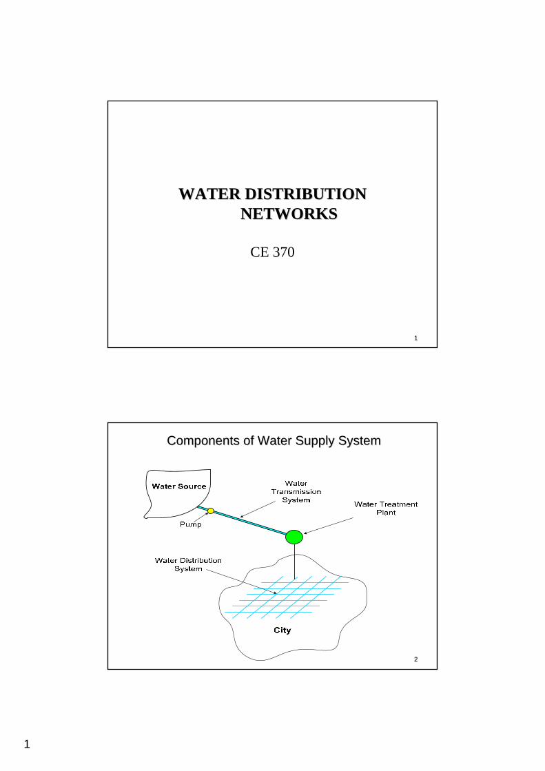
Components of Water Supply SystemComponents of Water Supply System
2
33
Water Transportation SystemWater Transportation System
Types of transportation systems:Various types of conduits can be used for transporting water. The selection depends on factors such as: topography, head availability, construction practices, economic considerations, and water quality. The types of transportation systems include:
•• Open channels.Open channels.
•• PipelinesPipelines
•• TunnelsTunnels
44
Water Transportation SystemWater Transportation System
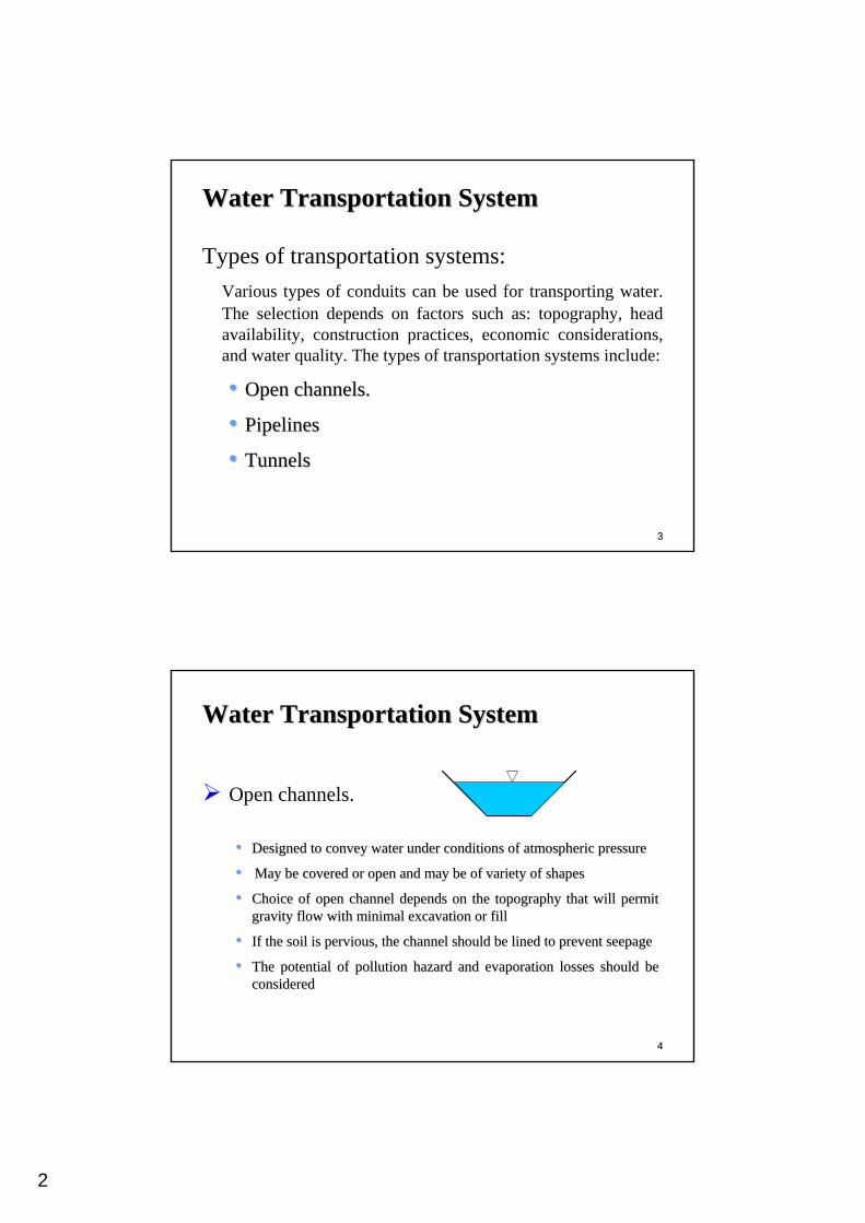
Open channels.
•• Designed to convey water under conditions of atmospheric pressurDesigned to convey water under conditions of atmospheric pressuree
•• May be covered or open and may be of variety of shapesMay be covered or open and may be of variety of shapes
•• Choice of open channel depends on the topography that will permiChoice of open channel depends on the topography that will permit t gravity flow with minimal excavation or fillgravity flow with minimal excavation or fill
•• If the soil is pervious, the channel should be lined to prevent If the soil is pervious, the channel should be lined to prevent seepageseepage
•• The potential of pollution hazard and evaporation losses should The potential of pollution hazard and evaporation losses should be be consideredconsidered
3
55
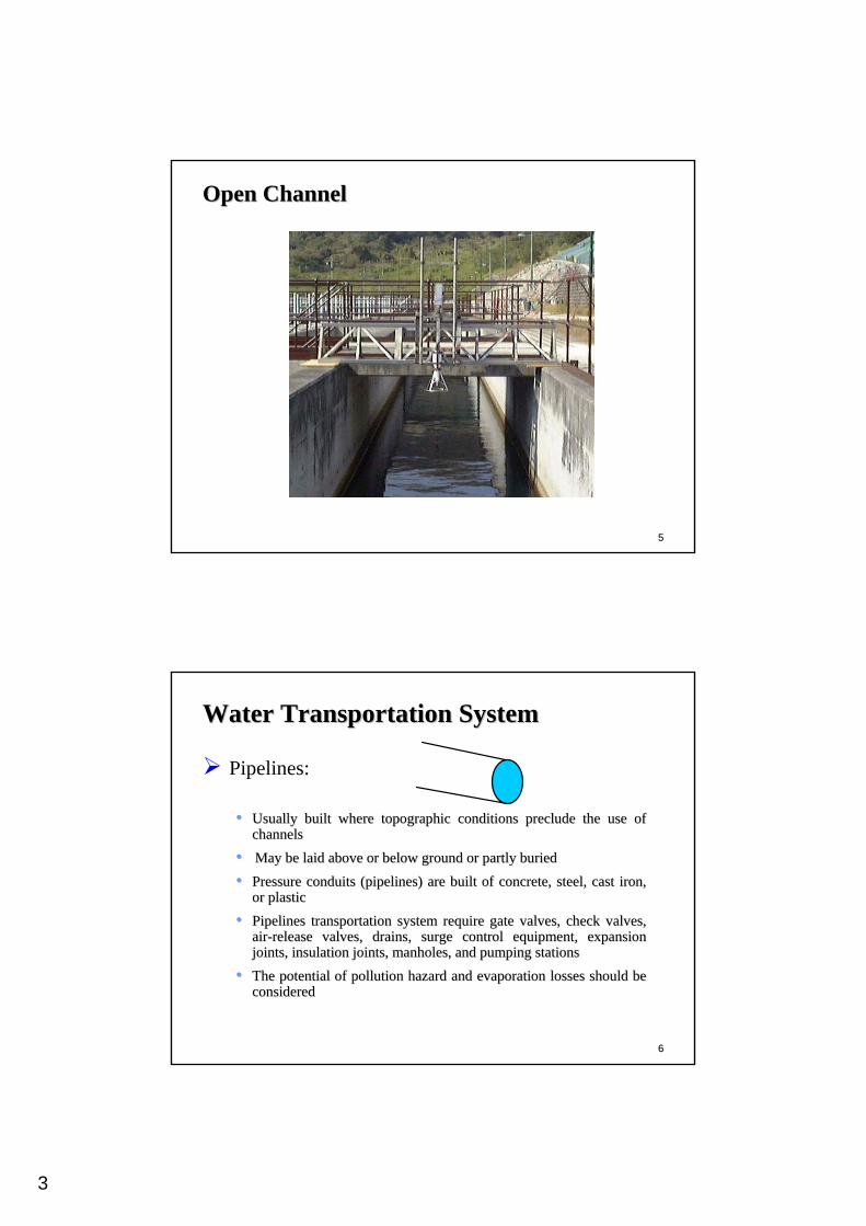
Open ChannelOpen Channel
66
Water Transportation SystemWater Transportation System
Pipelines:
•• Usually built where topographic conditions preclude the use of Usually built where topographic conditions preclude the use of channelschannels
•• May be laid above or below ground or partly buriedMay be laid above or below ground or partly buried
•• Pressure conduits (pipelines) are built of concrete, steel, castPressure conduits (pipelines) are built of concrete, steel, cast iron, iron, or plasticor plastic
•• Pipelines transportation system require gate valves, check valvePipelines transportation system require gate valves, check valves, s, airair--release valves, drains, surge control equipment, expansion release valves, drains, surge control equipment, expansion joints, insulation joints, manholes, and pumping stationsjoints, insulation joints, manholes, and pumping stations
•• The potential of pollution hazard and evaporation losses should The potential of pollution hazard and evaporation losses should be be consideredconsidered
4
77
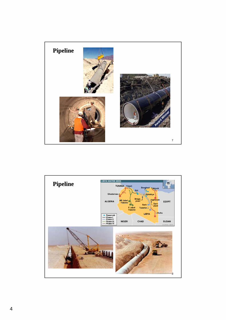
PipelinePipeline
88
PipelinePipeline
5
99
Water Transportation SystemWater Transportation System
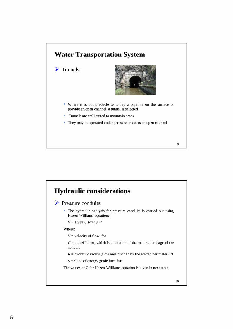
Tunnels:
•• Where it is not Where it is not practiclepracticle to to toto lay a pipeline on the surface or lay a pipeline on the surface or provide an open channel, a tunnel is selectedprovide an open channel, a tunnel is selected
•• Tunnels are well suited to mountain areasTunnels are well suited to mountain areas
•• They may be operated under pressure or act as an open channelThey may be operated under pressure or act as an open channel
1010
Hydraulic considerationsHydraulic considerations
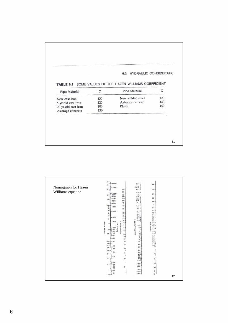
Pressure conduits:• The hydraulic analysis for pressure conduits is carried out using
Hazen-Williams equation:
V = 1.318 C R0.63 S 0.54
Where:
V = velocity of flow, fps
C = a coefficient, which is a function of the material and age of the conduit
R = hydraulic radius (flow area divided by the wetted perimeter), ft
S = slope of energy grade line, ft/ft
The values of C for Hazen-Williams equation is given in next table.
6
1111
1212
Nomograph for Hazen Williams equation
7
1313
Hydraulic considerationsHydraulic considerations
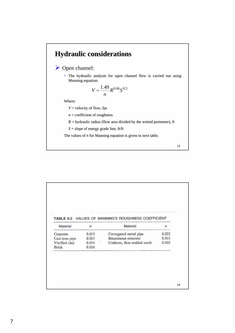
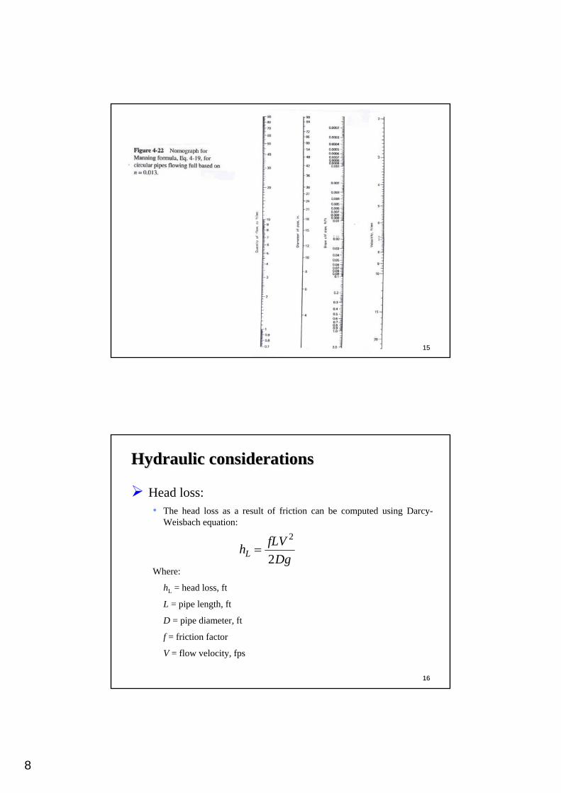
Open channel:•• The hydraulic analysis for open channel flow is carried out usinThe hydraulic analysis for open channel flow is carried out using g
Manning equation:Manning equation:
Where:Where:
VV = velocity of flow, fps= velocity of flow, fps
nn = coefficient of roughness= coefficient of roughness
RR = hydraulic radius (flow area divided by the wetted perimeter),= hydraulic radius (flow area divided by the wetted perimeter), ftft
SS = slope of energy grade line, ft/ft= slope of energy grade line, ft/ft
The values of The values of nn for Manning equation is given in next table. for Manning equation is given in next table.
5.066.049.1 SRn
V =
1414
8
1515
1616
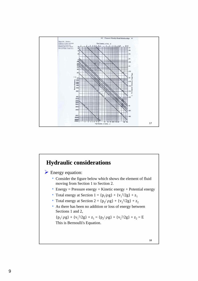
Hydraulic considerationsHydraulic considerations
Head loss:• The head loss as a result of friction can be computed using Darcy-
Weisbach equation:
Where:
hL = head loss, ft
L = pipe length, ft
D = pipe diameter, ft
f = friction factor
V = flow velocity, fps
DgfLVhL 2
2=
9
1717
1818
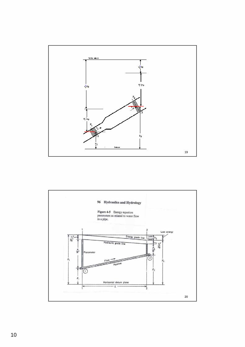
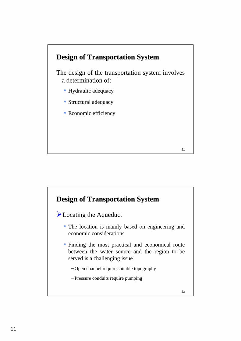
Hydraulic considerationsHydraulic considerationsEnergy equation:• Consider the figure below which shows the element of fluid
moving from Section 1 to Section 2.• Energy = Pressure energy + Kinetic energy + Potential energy• Total energy at Section 1 = {p1/ρg} + {v1
2/2g} + z1
• Total energy at Section 2 = {p2/ ρg} + {v22/2g} + z2
• As there has been no addition or loss of energy between Sections 1 and 2, {p1/ ρg} + {v1
2/2g} + z1 = {p2/ ρg} + {v22/2g} + z2 = E
This is Bernoulli's Equation.
10
1919
2020
11
2121
Design of Transportation SystemDesign of Transportation System
The design of the transportation system involves a determination of:•• Hydraulic adequacyHydraulic adequacy
•• Structural adequacyStructural adequacy
•• Economic efficiencyEconomic efficiency
2222
Design of Transportation SystemDesign of Transportation System
Locating the Aqueduct
• The location is mainly based on engineering and economic considerations
• Finding the most practical and economical route between the water source and the region to be served is a challenging issue
−Open channel require suitable topography
−Pressure conduits require pumping
12
2323
Design of Transportation SystemDesign of Transportation System
Dimensions of Aqueduct• The size will be determined on the basis of hydraulic,
economic, and construction considerations.
• Hydraulic factors that control the design are:−Available head−Limiting velocities
– Minimum velocity is 2.5 fps (prevent silt deposition)– Maximum velocity between 10-20 fps (reduce pipe
erosion)
2424
13
2525