water enterprise - sfpuc
TRANSCRIPT

WATER ENTERPRISE
CITY DISTRIBUTION DIVISION
Standard Specifications for Installation of Ductile Iron Water Mains 16-Inches and Smaller
JANUARY 2020


By: 2-K -0
Date Raymond Tan, P.E. Civil Engineer
Approved:
Recommended:
anh Nguy , P.E. enior Civil Engineer
RECOMMENDATIONS/APPROVALS
Eugene Shu, P.E. Date Engineering Section Manager (Acting)
Approved: 2010
Richard Gonzj&5 Construction & Maintenance Superintendent
Date
Approved: /a z
Bill Teahan, D5 Date City Distribution Division Manager
CITY DISTRIBUTION DIVISION STANDARD SPECIFICATIONS FOR INSTALLATION OF WATER MAINS 16-INCHES AND SMALLER


CITY DISTRIBUTION DIVISION STANDARD SPECIFICATIONS FOR INSTALLATION OF WATER MAINS 16-INCHES AND SMALLER
TABLE OF CONTENTS
SECTION TITLE
01 11 00 GENERAL REQUIREMENTS
01 41 28 PROTECTION OF EXISTING WATER AND AWSS FACILITIES
01 78 39 PROJECT RECORD DOCUMENTS
31 23 36 EXCAVATION AND BACKFILL
32 10 00 PAVEMENT RESTORATION
33 10 00 WATER UTILITY PIPING MATERIALS
33 11 00 INSTALLATION OF 16-INCH AND SMALLER WATER MAINS AND APPURTUNANCES
33 11 41 POLYETHYLENE ENCASEMENT OF DUCTILE IRON PIPE
33 11 43 REMOVAL OF SFPUC-CDD/SFWD OWNED VALVE BOXES
33 12 13 INSTALLATION OF SCREW TAPS, SERVICE PIPE AND FITTINGS
33 13 00 SANITARY WORK PRACTICES AND DISINFECTION OF WATER UTILITY DISTRIBUTION


Standard Specifications for the Installation of Ductile Iron Water Mains 16-Inches and Smaller
January 2020 01-11-00 - 2 General Requirements
SECTION 01 11 00
GENERAL REQUIREMENTS
PART 1 – GENERAL
1.01 MASTER PLAN
A. A master plan shall be developed for potable water piping network to serve the entire built-out development area.
B. For each phase of the development, a separate plan shall be developed to serve the development within the phase. Plans developed for phases shall be consistent with the master plan.
1.02 DESIGN WATER PRESSURE & FLOW
A. All potable water mains shall be designed to water pressure and flow for maximum domestic daily demand plus fire flow requirements. Fire flow and residual pressure shall be as required by SFFD.
1.03 REFERENCE STANDARDS
A. Standard Specifications of the City and County of San Francisco (the City), Department of Public Works (DPW), Bureau of Engineering (BOE), dated July, 1986. Also referred to as “City Standard Specifications.”
B. Standard Plans of the City, DPW, BOE, dated September 1987. Also referred to as “City Standard Plans.”
C. DPW Order No. 187,005 "Regulations for Excavations and Restoring Streets in San Francisco" approved in 2018.
D. American Water Works Association (AWWA) Standards, Latest Revision.
E. California Code of Regulations, Title 22, CA DPH
F. SFPUC (CDD) Standard Plans and Specifications
G. SFPUC Rules and Regulations Governing Water Service to Customers
H. SFPUC Asset Protection Standards, May 2017 or Latest Revision.
1.04 SUBMITTALS
A. The San Francisco Public Utilities Commission (SFPUC) requires that all reports, plans and specifications for a public water system be submitted at least 30 days prior to the date when their approval is desired.

Standard Specifications for the Installation of Ductile Iron Water Mains 16-Inches and Smaller
January 2020 01-11-00 - 3 General Requirements
B. Documents submitted for formal approval must include, but not be limited to:
1. Summary of the basis of design and hydraulic analysis report,
2. Design criteria and selection of materials and installation methods for water mains, isolation valves, hydrants, air valves, meters and blow-off valves, flow meters, backflow preventers, cathodic protection, restraint devices, separation between water mains, sanitary and storm sewers, cross-connections and interconnections, water services and plumbing, and service meters,
3. Operation requirements, where applicable,
4. General layout showing the extent of the proposed system,
5. Detailed plans and specifications by a Professional Engineer licensed in the State of California,
6. Baseline schedule with monthly update,
7. Documentation stating that the developer is committed to providing as-built certification of the project in drawings stamped by a registered professional engineer acting as the Engineer of Record for the development, and
8. Hydrostatic test plan.
C. The developer is responsible to obtain all other necessary permits for construction, waste discharges, etc., required by other federal, state, or local agencies. No approval for construction can be issued until final, complete, detailed plans and specifications have been submitted to the reviewing authority and found to be satisfactory. Three sets of the final plans and specifications must be submitted for review and approval. SFPUC- CDD will review and provide comments within 30 days of receiving the set for review. Incomplete drawing and specification sets will be returned without review. An approved set stamped by CDD Engineering Department will be returned to the applicant.
D. For progress review plans: Three full-sized sets of submittals must be delivered to the SFPUC-CDD. Two (2) hard copies shall be mailed to City Distribution Division ATTN: Engineering Department 1990 Newcomb Avenue San Francisco, CA 94124
One (1) pdf electronic copy must also be transmitted to [email protected].
1.05 INSPECTION

Standard Specifications for the Installation of Ductile Iron Water Mains 16-Inches and Smaller
January 2020 01-11-00 - 4 General Requirements
All work performed by Contractor will be subject to inspection by SFPUC-CDD. Work or material that does not conform to the specifications will be rejected at any stage of construction. The Contractor shall be responsible for additional costs incurred for subsequent inspection of the new work.
1.06 CONTRACTOR’S LICENSE
An active Class “A” California Contractor License is required to perform the water work. Each subcontractor must possess appropriate licenses for work each subcontractor will be performing.
1.07 PERMITS
Contractor shall obtain and pay for all required permits, inspections and service requests to start and complete work.
1.08 WARRANTIES
A. The Project Developer’s Contractor shall warrant that work performed is free of any defect of equipment, equipment system, material, installation, design furnished, or workmanship furnished by Contractor, and/or Contractor’s subcontractors, suppliers, manufacturers and design professionals for 24 months following the date of the Certification of Acceptance issued by SFPUC-CDD.
B. The Project Developer’s Contractor shall provide warranty documents for each equipment and each equipment system, whether the entity is a supplier (which assembles various manufactured parts and then provides a warranty for the equipment system); a manufacturer (which may subcontract a certain part(s) but provides a warranty for the entire equipment system furnished or which provides a warranty for each individual piece of equipment furnished); or the Contractor itself.
C. The Warranty material shall be submitted in commercial quality, 8-1/2 inch x 11 inch three-ring side binders with hardback, cleanable, plastic covers. The Project Developer’s Contractor shall label the cover of each binder with typed or printed title WARRANTIES, with title of the Project; name, address and telephone number of Contractor and name of Contractor’s responsible principal employee.
D. The Project Developer’s Contractor shall provide a neatly typed Warranty Table of Contents as shown in the sample form provided in this Section.
E. The required guarantees/warranties executed by the Project Developer’s Contractor and its subcontractor, installer, supplier, or manufacturer (if applicable) responsible for that portion of the work are subject to the City's verification that the documents are in proper form and contain complete information. The Project Developer’s Contractor shall correct and resubmit deficient guarantees/warranties before Final Completion of the Project.
F. Warranty Table of Contents Sample Form

Standard Specifications for the Installation of Ductile Iron Water Mains 16-Inches and Smaller
January 2020 01-11-00 - 5 General Requirements
Specification Section
Description of Equipment or Equipment System
Guarantor Guarantee/ Warranty Duration
Name of Equipment or Equipment System Manufacturer

Standard Specifications for the Installation of Ductile Iron Water Mains 16-Inches and Smaller
January 2020 01-11-00 - 6 General Requirements
G. For the Entire Project, the Project Developer’s Contractor shall submit a certificate covering the Guarantee to Repair Period as follows:
GUARANTEE/WARRANTY FOR SFPUC
Project Title and Description: (Provide title, location and general description of the project.)
We hereby guarantee/warrant that the work of this Contract has been completed in accordance with the requirements of all applicable Contract Documents. We agree to repair or replace any or all of our Work that may prove to be defective in its workmanship, material, or Contractor-furnished design within a period of twenty-four (24) months from the date of issuance of the Certification of Acceptance by SFPUC-CDD of the above named Project. We also agree to repair or replace any adjacent work which may be damaged as a result of the defective work or as a result of repairing or replacing defective work. We agree to repair any and all damages resulting from defective work without any expense to the City, ordinary wear and tear and unusual abuse or neglect excepted. In the event of our failure to comply with the above mentioned conditions within ten (10) days after being notified in writing by the City, we collectively or separately do hereby authorize the City to proceed to have such defective work repaired or replaced and made good at our expense, and we will honor and pay the costs and charges therefore upon demand. Signed_____________________________ Date _______________
Contractor Name: _______________________________________ Address:_______________________________________________ License No. ________________
Final Completion of the work was granted by the City on _____________ (date)
Signed: ___________________________ Date:_______________ (City Representative)
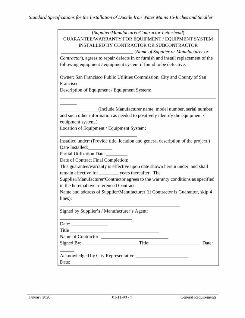
H. The Project Developer’s Contractor shall submit Supplier/Manufacturer/Contractor Warranties for Specific Items of Equipment or Equipment Systems in accordance with the quality and performance standards detailed in Technical Specifications
Standard Specifications for the Installation of Ductile Iron Water Mains 16-Inches and Smaller
January 2020 01-11-00 - 7 General Requirements
(Supplier/Manufacturer/Contractor Letterhead)
GUARANTEE/WARRANTY FOR EQUIPMENT / EQUIPMENT SYSTEM INSTALLED BY CONTRACTOR OR SUBCONTRACTOR
______________________________ (Name of Supplier or Manufacturer or Contractor), agrees to repair defects in or furnish and install replacement of the following equipment / equipment system if found to be defective. Owner: San Francisco Public Utilities Commission, City and County of San Francisco Description of Equipment / Equipment System: ________________________________________________________________________ ________________(Include Manufacturer name, model number, serial number, and such other information as needed to positively identify the equipment / equipment system.) Location of Equipment / Equipment System: ________________________________ Installed under: (Provide title, location and general description of the project.) Date Installed:__________ Partial Utilization Date:_________ Date of Contract Final Completion:____________ This guarantee/warranty is effective upon date shown herein under, and shall remain effective for ________ years thereafter. The Supplier/Manufacturer/Contractor agrees to the warranty conditions as specified in the hereinabove referenced Contract. Name and address of Supplier/Manufacturer (if Contractor is Guarantor, skip 4 lines): __________________________________________________ Signed by Supplier’s / Manufacturer’s Agent: ______________________________ Date: _______________ Title _____________________________________ Name of Contractor: ____________________________ Signed By: _______________________ Title:_____________________ Date: ______ Acknowledged by City Representative:______________________ Date:___________

Standard Specifications for the Installation of Ductile Iron Water Mains 16-Inches and Smaller
January 2020 01-11-00 - 8 General Requirements
PART 2 – PRODUCTS
Ductile iron, copper and brass products listed hereinafter are currently used by SFPUC-CDD for the installation of water mains and services in soil commonly found in San Francisco. Refer to latest SFPUC material term contracts for approved makes and models.
2.01 DISTRIBUTION AND FEEDER/TRANSMISSION MAINS
A. Minimum size of distribution water mains shall be 8 inches. Pipe diameters of 10 and 14 inches shall not be used.
B. SFPUC-CDD uses ductile iron pipe, Class 53, double cement lined (inside), coated (outside) with a layer of arc-sprayed zinc coating.
C. For 8-inch distribution mains outside of liquefaction-susceptible areas: TYTON® joint with FIELD LOK®gaskets or approved equal shall be used.
D. For mains larger than 8-inch diameter: Flex-Ring® joint pipe and fittings with Fastite® gaskets or TR FLEX® joint pipe and fittings with TYTON® gaskets shall be used
2.02 SERVICE PIPES
A. The allowable diameters for service pipes are 1-, 2-, 4-, 6-, 8-, and 12-inches. Pipe diameters of 3 inches and less than 1-inch shall not be used.
B. Service pipes larger than 2-inch shall be ductile iron pipe.
C. 2-inch and smaller service pipes shall be copper tubing type K, soft or hard. Fittings shall be made of bronze or brass, in conformance with AWWA C-800.
2.03 GATE VALVES
A. 12-inch and smaller gate valves shall be TYTON® by TYTON® ends, with FIELD LOK® gaskets, resilient seated, non-rising stem, right turn open and nut operated. Additional restraint shall be provided for gate valves off tee branches as per Standard Plan CDD-LP-006.
B. 16-inch gate valves shall be mechanical joint ends restrained with EBAA megalug mechanical joint glands, resilient seated, non-rising stem, right turn open and nut operated.
C. Flanged end gate valves shall be full-face flange by flange manufactured in accordance with ANSI B16.1, 125 lb. class or ANSI B16.2, 250 lb. class, resilient seated, non-rising stem, right turn open and nut operated.
2.04 DUCTILE IRON FITTINGS
A. SFPUC-CDD uses ductile iron fittings to connect ductile iron pipes.

Standard Specifications for the Installation of Ductile Iron Water Mains 16-Inches and Smaller
January 2020 01-11-00 - 9 General Requirements
B. Ductile iron fittings shall conform to the latest revision of ANSI/AWWA C110/A21.10. Fittings shall be TYTON® by TYTON® ends with FIELD LOK® gaskets for 8-inch and smaller mains, and Flex-Ring® with Fastite® gasket or TR Flex with TYTON® gaskets for larger than 8-inch mains.
C. The ductile iron fittings shall be cement-mortar lined (inside) conforming to ANSI/ASTM C104/A21 and shall be double the standard thickness and zinc-rich paint coating (outside).
2.05 V-BIO POLYETHYLENE ENCASEMENT
A. All pipes and fittings, including service laterals, shall be encased in an 8 mil, low density V-bio polyethylene casing in accordance with ANSI/AWWA C105/A21.5. The tape to secure polyethylene encasement over pipe barrels shall be blue polyethylene adhesive tape.
2.06 JOINT RESTRAINT DEVICES
A. Joint restraint devices shall be per SFPUC-CDD standard drawings. Bolts, nuts, tie-rods, lugs and bands shall be stainless steel type 304 or 316.
2.07 AIR OR BLOW-OFF VALVE
A. 2-inch air valves and blow-off valves shall be manual type and the assembly shall be as shown in SFPUC-CDD Standard Plans CDD-LP-003, latest revision. 4-, 6- and 8- inch blow offs shall be installed per CDD-LP-003. 4-, 6- and 8- inch automatic air-relief and vacuum break valves (ARVB) must be installed by SFPUC-CDD personnel. The ARVB enclosure shall be installed by the contractor per Standard Plan CDD-LP-255 and -256.
2.08 WATER METER BOXES, VAULTS, AND COVERS
A. Meter boxes and covers for standard 1- and 2-inch (domestic) services shall be made of polyethylene and polymer concrete. Meter vaults for services larger than 2-inch shall be fiberglass vaults with torsion assisted frame and cover. Meter boxes, vaults and covers shall be manufactured by Armorcast or approved equivalent and shall be installed as shown in SFPUC-CDD Standard Plans, latest revision
2.09 HYDRANT, HYDRANT BURY, BREAK AWAY
A. Low pressure hydrant, hydrant bury and break away shall be installed as shown in Standard Plan CDD-LP-004, latest revision. Hydrant shall be Long Beach Iron Works Model 621, with valve assembly specified in SFFD specifications for low pressure hydrants. Hydrants shall be painted as required by SFFD.
2.10 BACKFLOW PREVENTER
Type of backflow preventer shall be determined by the SFPUC- Water Quality Division.

Standard Specifications for the Installation of Ductile Iron Water Mains 16-Inches and Smaller
January 2020 01-11-00 - 10 General Requirements
END OF DOCUMENT


Standard Specifications for the Installation of Ductile Iron Water Mains 16-Inches and Smaller
January 2020 01 41 28 - 1 Protection of Existing Water and AWSS Facilities
SECTION 01 41 28
PROTECTION OF EXISTING WATER AND AWSS FACILITIES PART 1 – GENERAL 1.1 DESCRIPTION
A. Contractors performing excavation adjacent to or below the San Francisco
Public Utilities Commission’s (SFPUC) Potable Water (PW), Recycled Water (RW), and Auxiliary Water Supply System (AWSS) facilities to protect those facilities throughout the duration of their respective projects. Contractor will be held responsible for any damage related to or caused by failure to exercise due care. Repair of existing utilities and improvements damaged during construction shall be at the Contractor’s expense.
B. Contractor shall be required to prepare or obtain settlement monitoring plans, approved by SFPUC – City Distribution Division (CDD) Engineering Section, prior to performing work adjacent to or around SFPUC’s AWSS System when required as specified hereinafter. If contractor is unable to prepare Settlement Monitoring Plans, contractor may request plans be prepared, at Contractors Expense, by making the request in writing via email to. [email protected]
C. The Contractor shall furnish, install and remove upon completion of the work,
Settlement Reference Points (SRP) and Settlement Monitoring Points (SMP) for the SFPUC AWSS piping as shown on the settlement monitoring plan and conduct the survey of SRPs and SMPs as specified hereinafter.
D. The Contractor shall perform all required work as stated in this specification
section and as shown on the Drawing(s) and furnish all materials, other than those specified to be furnished by the City, which are necessary or required to complete the work.
1.2 RELATED WORK SPECIFIED ELSEWHERE
Not used.
1.3 RECORD DRAWINGS AND STANDARDS
Records of the existing PW, RW, and AWSS facilities and Standard requirements are available for examination by bidders/awarded Contractor upon request by emailing [email protected].

Standard Specifications for the Installation of Ductile Iron Water Mains 16-Inches and Smaller
January 2020 01 41 28 - 2 Protection of Existing Water and AWSS Facilities
Contractors are warned that changes which do not appear in the records for existing CDD facilities may have been made. The City makes no representation as to the completeness or accuracy of said records and assumes no responsibility thereto.
1.4 DEFINITIONS A. Maximum Allowable Settlement: Level at which no further movement will be
acceptable and if reached requires work to be halted until submittal and acceptance of a written plan detailing corrective actions and restorative measures.
B. Response Values: Predetermined values within the instrument range indicating
different levels of response as specified herein. C. Settlement Monitoring Point: A system of points along the alignment of the
AWSS for monitoring vertical deformation (settlement or heave) at or near the ground surface using optical survey techniques.
E. Settlement Reference Point: A stable, fixed control point established at a
surface structure above ground that is referenced during settlement monitoring point measurements to permit calculation of vertical movements.
1.5 REFERENCES
A. AWSS Standard Plans
Drawing No. Title
CDD-HP-401 AWSS Settlement Point For Bell & Spigot Pipe
CDD-HP-402 AWSS Settlement Point for Double
Spigot Pipe
B. AWSS Settlement Monitoring Drawings in the Contract showing approximate locations of settlement monitoring and reference points.
C. State of California Labor Code, Section 6705 and 6707. D. State of California Construction Safety Orders, Article 6 - Excavation.
1.6 SUBMITTALS
Submit the following to City Representative for review and acceptance. Work shall not start until acceptance of submittals:

Standard Specifications for the Installation of Ductile Iron Water Mains 16-Inches and Smaller
January 2020 01 41 28 - 3 Protection of Existing Water and AWSS Facilities
A. Work plan, support details, and calculations.
1) Work Plan for working around existing PW, RW, and AWSS facilities
within the influence zone of the excavation. The plan shall show the locations of proposed facilities, existing utilities and pipelines, proposed pipe supports for SFPUC-CDD facilities, pipe storage, spoil bank, excavation and pipe laying equipment, shoring system, and a description of how the work will proceed around the existing SFPUC-CDD facilities. Provide drawings that include dimensions to allow determining the distances of objects relative to the SFPUC-CDD facilities. Sizes of existing and proposed facilities, width and depth of proposed trench, and any other pertinent information must be shown in the drawings. For proposed structural facilities, such as retaining walls and tie back walls, potentially impacting CDD facilities, submit elevation and or section views showing horizontal and vertical locations of CDD facilities relative to the proposed structure.
2) Where supports are required per this specification, submit support details and calculations, signed and stamped by a California licensed Civil or Structural Engineer, for structural support for the protection of exposed and/or undermined sections of SFPUC-CDD pipe or facilities. At the discretion of SFPUC-CDD Engineering, revised support details and calculations may be required to be submitted if conditions vary significantly following excavation.
3) Submit minimum twenty-one (21) calendar days before planned
excavation. B. Control Density Fill (CDF) mix design where CDF is required per this
Specification. Submit certified laboratory test results within the past 1-year that the mix proportions and materials comply with these Specifications.
C. Survey of Settlement Reference and Monitoring Points data: The Contractor shall submit elevations of all SMPs and SRPs (to be provided in “feet”) by a State of California licensed Land Surveyor in addition to deflection calculations for each pipe joint. Data and calculations shall be submitted once prior to the start of construction, once a week during construction, once at the end of construction and final survey is completed, and when threshold values are exceeded as specified below. Pipe deflection angles and elevation readings calculated from SMPs and SRPs are to be tabulated in chronological order with all previous results for review and approval within 24 hours of the survey being performed.

Standard Specifications for the Installation of Ductile Iron Water Mains 16-Inches and Smaller
January 2020 01 41 28 - 4 Protection of Existing Water and AWSS Facilities
PART 2 – PRODUCTS 2.1 CONTROLLED DENSITY FILL
A. Materials shall conform to the following.
1) Cement: ASTM C150, Type II or V.
2) Aggregate: ASTM C33. Aggregate shall consist of fine aggregate with a maximum size of 1/4", free of clay, organics, and other deleterious materials. Less than 10 percent by weight shall pass the No. 200 sieve, and material passing the No. 40 sieve shall be non-plastic as determined in accordance with ASTM D4318.
3) Water: Potable.
4) Pozzolans: ASTM C618, Class C fly ash. Class F fly ash and slag is not permitted.
5) Air entraining: ASTM C260. Air content shall not exceed 25 percent.
6) Admixtures: Shall not contain chloride ions and shall not cause delayed strength gain.
B. Mixes:
1) Performance requirement: proportioned to be free-flowing, self-
consolidating, hand tool excavatable, low-shrink slurry.
2) Mix design requirement: The Contractor and its supplier shall determine the materials and proportions used to meet the requirements of the Specifications.
3) Strength: Unconfined compressive strength at 28 days shall be less than 100 psi tested per ASTM D 4832.
4) Flowability: 6 to 9 inches when tested per ASTM C-143 or ASTM D 6103.
5) Cementitious Material: Portland Cement. Where pozzolans are used, pozzolans shall be limited to maximum 60% of the weight of cement.
2.2 AWSS SETTLEMENT REFERENCE AND MONITORING POINTS

Standard Specifications for the Installation of Ductile Iron Water Mains 16-Inches and Smaller
January 2020 01 41 28 - 5 Protection of Existing Water and AWSS Facilities
A. AWSS Settlement Reference and Monitoring Well Covers: 6-inch valve cover, H-20 load rated, cover similar to the San Francisco Water
Department’s 6-inch gate valve cover. B. Required survey monitoring of AWSS facilities outside of trenches and/or
excavations:
1) Refer to the AWSS Settlement Monitoring Drawing(s) for the location of SMPs to be installed as part of the contract work; and
2) For trench/excavation crossing AWSS, the SMPs shall be located starting on the closest pipe bell near the edge of the trench and/or excavation and installed outward away from the trench and/or excavation; and
3) Rod, guide pipe, and monitoring well shall be per Drawings CDD-HP-
401 and CDD-HP-402, which are available for download at sfwater.org/waterplans.
C. Required monitoring of AWSS facilities inside of trenches and/or excavations:
1) Exposed AWSS pipe joints in trenches and/or excavations shall be identified as a SMP regardless of whether the joint is called out on the AWSS Settlement Monitoring Drawing(s) to be surveyed and monitored. Field verification of the exact location shall be required and approved by SFPUC-CDD Engineering.
2) Additional SMPs within trenches and/or excavations may be necessary on either or both sides of the AWSS joint to distinguish the difference between vertical displacement and joint deflection.
D. Placement of SRP(s) for survey monitoring of SMPs:
1) A settlement reference point shall be designated by a marking on a
hydrant or other stable, permanent fixture located within the public right-of-way. The same location shall be surveyed for reference over the course of the project. Refer to the AWSS Settlement Monitoring Drawing(s) for the location of SRP(s) to be installed as part of the survey monitoring work.
PART 3 – EXECUTION

Standard Specifications for the Installation of Ductile Iron Water Mains 16-Inches and Smaller
January 2020 01 41 28 - 6 Protection of Existing Water and AWSS Facilities
3.1 SUPPORT AND REPLACEMENT OF EXISTING PW, RW, AND AWSS FACILITIES WITHIN THE INFLUENCE ZONE
A. Inspection, Review and Approval of Methods
1) The influence zone is defined as the trench/excavation and the 45 degree
soil wedge on the sides of the excavation as shown in the figure above. The Contractor shall contact CDD Engineering prior to doing any work inside the influence zone.
2) If existing SFPUC-CDD facility, not shown on the drawing or is shown on the drawing outside of the influence zone, is found to be within the influence zone, the Contractor is required to contact CDD Engineering and request an inspection to review and approve the field methods being used and/or proposed for the protection of CDD facility.
3) If two or more consecutive SFPUC-CDD lead filled, cast-iron pipe joints are located within the trench/excavation, CDD requires replacement of the existing pipe with new ductile iron pipe with elastomeric EPDM joint gaskets within the influence zone.
4) Existing valves exposed in trench/excavation:
a) If existing valve with lead filled joints is exposed within the
trench/excavation, CDD requires replacement of the existing valve and cast-iron pipe with new ductile iron pipe with elastomeric EPDM joint gaskets within the influence zone.
b) If existing valve with restrained elastomeric gasketed joints connecting to ductile-iron pipe is exposed within trench/excavation, pipe support requirement shall be the same as that for ductile-iron pipe as specified in the following requirement. If valve is not restrained, restraints shall be added by CDD at the project owner’s cost.
5) Pipe supports are required where CDD pipe is exposed more than:
a) 6 ft. for cast-iron pipe with no exposed joint. b) 3.5 ft. for cast-iron pipe with exposed joint.

Standard Specifications for the Installation of Ductile Iron Water Mains 16-Inches and Smaller
January 2020 01 41 28 - 7 Protection of Existing Water and AWSS Facilities
c) 10 ft. for ductile-iron pipe with no exposed joint. d) 6 ft. for ductile iron pipe with exposed joint(s).
6) Sheet pile driving adjacent to existing CDD pipe shall maintain a
minimum clear spacing between back of sheet pile and edge of pipe of: a) 1.5 ft. for ductile iron pipes. b) 4 ft. for cast-iron pipes. If within 4 ft., settlement monitoring is
required for both LPW and AWSS lines. Settlement monitoring of LPW lines shall be the same as for AWSS lines unless approved otherwise by CDD Engineering.
7) Main disconnection/reconnection for PW and RW shall be performed by
SFPUC-CDD. Pipe, valve, fittings, hydrants, and all necessary work not stated to be performed by SFPUC-CDD shall be performed by the Contractor. Excavation, backfilling, paving, traffic control, permitting, and any other support work necessary for the PW and RW replacement work including work to be performed by SFPUC-CDD shall be the Contractor’s responsibility. All AWSS replacement work shall be performed by Contractor or subcontractor qualified by CDD to perform AWSS main installation. All replacement valves and piping for CDD replacement is supplied by CDD.
8) Submit details and calculations for structural support for the protection
of exposed and/or undermined sections of SFPUC-CDD facilities if required per this specification. Details and calculations shall be signed and stamped by a California licensed Civil or Structural Engineer. Structural supports shall be designed to protect (1) AWSS pipes constructed with Class H cast iron lead jointed pipe operating at 350 psi static pressure, (2) AWSS pipes constructed with Class 56 ductile iron pipe, (3) PW pipes constructed with Class B cast iron lead jointed pipe operating at 150 psi static pressure, and (4) PW or RW pipes constructed with Class 53 ductile iron pipe operating at 150 psi static pressure. Maximum deflection in pipe support members shall not exceed L/500, where L is the unsupported length of the member.
B. Restoration of Facilities
If project work exposes CDD facilities, the Contractor is required to 1) backfill and compact in compliance with San Francisco Department of
Public Works (SFDPW) Street Excavation; and 2) perform soil compaction testing for backfill material placed within three
(3) feet, horizontally or vertically, from the outside edge of a water facility, with all test results furnished to CDD Engineering.
Standard Specifications for the Installation of Ductile Iron Water Mains 16-Inches and Smaller
January 2020 01 41 28 - 8 Protection of Existing Water and AWSS Facilities
For excavations that expose more than four (4) feet of CDD facilities or pipe joint (4-inch and smaller pipes are excluded), backfill is required to be constructed with control density fill (CDF) material.
CDF material shall begin at (3) feet below the CDD facility and continue up to the bottom of the CDD facility. CDF material shall not extend beyond the spring-line of any CDD facility. Width of CDF backfill shall be OD of CDD pipe + 1ft on each side. Compaction test must be performed on the backfill material below the CDD facility immediately before CDF placement.
3.2 INSTALLATION OF AWSS SETTLEMENT REFERENCE AND MONITORING POINTS AND SUPPORT OF PIPE
A. Installation
The SRPs and SMPs shall be installed prior to the start of construction work requiring excavation around AWSS pipe. For SRPs at fire hydrants, the contractor shall select the top center of fire hydrant. The contractor must ensure that the exact same point is used to establish survey control prior to monitoring of SMPs and additional SRPs. For installation of SMPs outside of trench/excavations, the Contractor shall expose the bell of the pipe so that the position of the guide pipe on the bell can be visually verified before backfilling. The installation method used shall not cause the guide pipe to move from its intended position. For installation of SMPs inside of trench/excavations, the Contractor shall verify the leveling rod is positioned on top of the pipe by verifying the pipe crown with a level vial and marking the exact location on the pipe to ensure consistent monitoring of the same point. The correct positioning of each SRP and SMP on the top of the pipe bell shall be verified and approved by a CDD Representative by visual inspection. To request an inspection by a CDD Representative, please contact CDD Engineering a minimum of five (5) business days in advance to schedule the inspection. It is the responsibility of the Contractor to maintain all SRP and SMP installations in working order at all times.
B. Removal

Standard Specifications for the Installation of Ductile Iron Water Mains 16-Inches and Smaller
January 2020 01 41 28 - 9 Protection of Existing Water and AWSS Facilities
The SMPs and SRPs shall be removed by the Contractor, including pipe guides, monitoring well frames and covers and the roadway restored to its original condition(s).
C. Survey of Settlement Reference and Monitoring Points 1) The Contractor shall obtain elevations of all SMPs and SRPs, by a State of
California licensed Land Surveyor.
2) Initial Survey: Record the elevations within an accuracy of 0.005 feet (1/16-inch) for each settlement monitoring point on all surveys. After completion of each instrument installation, take 3 sets of verification data readings for each instrument to demonstrate the adequacy of the installation, to demonstrate the proper operation and precision of the instrument, and to establish an initial value. Differential Leveling and Total station accuracy shall comply with the accuracy standard specified in Caltrans Second Order Differential Leveling Specifications and Second Order (Vertical) TSSS Survey Specifications respectively. If differential leveling survey method is used, a collimation (Two-Peg) test shall be performed to ensure accuracy within 0.003 feet prior to each survey run. Submit the initial readings to the City Representative.
3) Monitoring Schedule: Take readings of all SMPs and SRPs prior to the
start of construction, once after the construction work is completed on the city block and adjacent intersections, and a final time two weeks after all construction work is completed on the city block and adjacent intersections. Intermediate monitoring frequency during construction shall as a minimum comply with the following:
Monitoring Frequency During Sheet Pile Driving
Monitoring Frequency
During Excavation or
Backfill
Monitoring Frequency in or Around Open
Trench
Monitoring Frequency Away
from Open Trench Daily1 Daily2 3 Days3 Once4
Notes: 1 For SMP’s within 25 ft. of pile driving, monitor daily if pile installation using vibratory
hammer and every four hours if pile installation using impact hammer. 2 Daily for SMPs within 25 ft. of a trench section being actively excavated or backfilled. 3 Once every three days for SMPs within 25 ft. of an open trench after excavation is
completed and utilities are being installed. 4 Once after trench within 25 ft of SMP is completely backfilled unless directed otherwise
by the City Representative.

Standard Specifications for the Installation of Ductile Iron Water Mains 16-Inches and Smaller
January 2020 01 41 28 - 10 Protection of Existing Water and AWSS Facilities
4) Elevation readings from SMPs and SRPs are to be tabulated in chronological order with all previous results and sent to CDD Engineering within 24 hours of the survey being performed. Measurements shall be provided in “feet”. Provide a plot of measured values versus time, including a time history of construction activity likely to influence such readings.
D. Response Values and Required Actions
1) The Maximum Allowable Settlement shall not result in any joint
deflecting more than 1/4 degrees, where the deflection angle is calculated using this equation:
2) The response values are measured as a percentage of the Maximum Allowable Settlement. The Contractor shall abide by the following Response Values.
Threshold Value Contractor
Response Value Shutdown Value 50% 80% 100%
3) When a given response value is reached, the Contractor shall provide
written notice within the specified time and respond in accordance with the following: a) Threshold Value: The Contractor shall provide written notice within
24 hours of occurrence and meet with the City Representative within 24 hours of providing notice to discuss his means and method to determine what corrective actions, if any, shall be made to better control ground movement. Instrument readings shall be required on a daily basis, unless instructed otherwise, until five consecutive working days of readings do not worsen the settlement by more than 5% of the Maximum Allowable.
b) Contractor Response Value: The Contractor shall provide written notice and meet with the City Representative within 24 hours to discuss his means and method to determine what corrective actions

Standard Specifications for the Installation of Ductile Iron Water Mains 16-Inches and Smaller
January 2020 01 41 28 - 11 Protection of Existing Water and AWSS Facilities
shall be made to better control ground movement. The Contractor shall actively control ground movement in accordance with the corrective actions to prevent reaching the Shutdown Value:
c) Shutdown Value: Contractor shall stop all work immediately in the
vicinity of the AWSS facilities and provide written notice within one hour upon occurrence. The Contractor shall meet with the City Representative to develop a plan of action before the work can be resumed. A drop-test will be performed by CDD prior to continuation of work. If shutdown value is reached from surveys after completion of construction, a drop-test will be performed by CDD to determine if any repairs are required. Excavation, shoring, and restoration, if required, to expose affected AWSS facilities for visual inspection or repairs will be at the Contractor’s expense.
E. Arrangement with Utility Companies
The Contractor shall make all necessary arrangements with the public service utility companies and obtain all necessary permits for any work or alteration of facilities as may be required due to the above described work.
F. Street and Sidewalk Restoration Street and Sidewalk restoration shall include the replacement of traffic lane(s) and crosswalk stripes, parking stall markings, and curb painting that might be damaged during the installation/removal of the SRPs and SMPs construction. The Contractor shall perform preconstruction survey by photo and video to document the existing condition of Street and Sidewalk prior to doing any work in the area.
3.3 EXPOSE, TEST, AND REPAIR OF AWSS PIPES
A. Requirement of Repair Work The Contractor is hereby notified that change in deflection of an AWSS pipe joint in exceedance of the shut-down value may require individual joint repairs or replacement of all the pipes adjacent to the SRPs (on each side of the surveyed joints) showing deflection at CDD’s discretion.
If the CDD Representative determines that repairs are required, the Contractor will be responsible for preparing and restoring the site(s) for repairing the damaged joint(s). Repair of damaged joint(s) shall be done by CDD at Contractor’s expense. Site preparation and restoration for AWSS joint repair will include

Standard Specifications for the Installation of Ductile Iron Water Mains 16-Inches and Smaller
January 2020 01 41 28 - 12 Protection of Existing Water and AWSS Facilities
1) Contractor shall submit for review and approval by CDD Engineering,
structural plans and details for the support and protection of AWSS facilities in the vicinity during repair of the damaged joint;
2) Contractor shall support and protect AWSS facilities per approved
submittal(s);
3) Contractor shall excavate a trench as required by CDD Engineering to expose the damaged AWSS pipe joint for repair purposes;
4) Upon direction and approval from a CDD Representative, Contractor shall
remove support and protection devices, and restore facilities as described in this Section; and
5) CDD Representative shall inspect and approve all site preparation and
restoration for AWSS joint repair work.
B. Contractor Responsible for all Costs
Exposure and restoration, testing, replacement, and repair of existing AWSS facilities as described in this Section including furnishing of materials, labor, equipment including pump and tools necessary, or required, to do such work shall be at the expense of the Contractor. The Contractor shall be responsible for all CDD labor and material costs associated with repairing the damaged AWSS facilities.
C. Testing The pipe repairs/replacement shall require CDD to isolate the pipe by closing gate valve(s), testing the repaired/replaced pipe section at a pressure of 300 psi (or other pressure designated by CDD engineering depending on site-specific constraints), repair any joints showing leakage or lead extrusions during pressure testing, and reactivating the pipe. A CDD Representative will witness all pressure tests. The Contractor shall inform CDD Engineering a minimum of five (5) business days before all tests.
3.3 PROTECTION OF AWSS CISTERNS
A. Notify the City Representative When excavation is to occur within 4 feet of an AWSS cistern, the Contractor is required to contact CDD Engineering a minimum of 5 business days in

Standard Specifications for the Installation of Ductile Iron Water Mains 16-Inches and Smaller
January 2020 01 41 28 - 13 Protection of Existing Water and AWSS Facilities
advance to review the field methods being used and/or proposed for the protection of the cistern and to schedule a baseline visual inspection by a CDD representative.
B. Required Inspections
The Contractor must schedule with the CDD representative to perform the following inspections: 1) Baseline visual inspection prior to excavation: CDD representative will
take two measurements of the water surface within the cistern from grade separated by a minimum of 72 hours apart and document the water level measurements with the dates and times when these measurements were taken with signed acknowledgement by the CDD representative and the Contractor’s representative. This information will be used to establish a baseline leakage rate.
2) Prior to backfilling: CDD representative will verify that the minimum
clearances to the cistern roof and wall are met and inspect for any visible damages to the cistern that may be a result from construction activities.
3) Before and after pavement surface modifications: Where any excavation
occurs within the outside edge of the brick ring, the CDD representative shall inspect ground surface before excavation and after pavement restoration. Prior to excavation, the CDD representative will inspect existing conditions of the brick ring, frame and cover. If the frame and cover is within the limits of paving work, the CDD representative will inspect if the frame and cover is outdated, worn or cracked and the City will provide a newer version at no cost to the Contractor for replacement prior to paving unless damage was caused by the Contractor. After paving is completed, the CDD representative will inspect the installation of the brick rings, frame, and cover. It is the Contractor’s sole responsibility to ensure that the frame and cover is properly re-installed with the brick rings outlining the perimeter of the cistern.
4) After construction around cistern is completed: the Contractor must notify
the CDD representative within a week after pavement restoration is completed to schedule an inspection to re-measure the water level. If the water level has lowered, the cause of the leakage will be investigated. If the cause of leakage is determined a result of Contractor’s construction activities, all cost associated with the investigation and repair will be the Contractor’s responsibility.
C. Minimum Clearance

Standard Specifications for the Installation of Ductile Iron Water Mains 16-Inches and Smaller
January 2020 01 41 28 - 14 Protection of Existing Water and AWSS Facilities
Underground facilities must be installed with 12” horizontal clearance from the outside face of cistern wall and 12” vertical clearance from the top of the cistern roof.
END OF SECTION

Standard Specifications for the Installation of Ductile Iron Water Mains 16-Inches and Smaller
January 2020 01 78 39 - 1 Project Record Documents
SECTION 01 78 39
PROJECT RECORD DOCUMENTS
PART 1 – GENERAL
1.01 SUMMARY
A. This Section sets forth requirements and procedures for the Contractor/Developer to maintain updated Project Record Documents required under the Contract and to submit up-dated record documents to the City Representative.
B. Related Documents and Sections include:
1. Standard Plan CDD-LP-501 - Typical Method of Measuring, Recording and Identifying Mains, Services, Gate Valves and All Appurtenances
2. Standard Plan CDD-LP-502 - Minimum Information Required for Domestic and Recycled Water As-Built Drawings
1.02 GENERAL REQUIREMENTS
A. The Contractor is responsible for maintaining up-to-date project record documentation. The Contractor shall make the up-to-date record documentation available for monthly inspection by the City Representative, and at any other time requested by the City Representative.
B. The Contractor is responsible for maintaining two sets of Project Record Documents: one on-site working set and another one in a secure, off-site location, so that in the event of loss of the Project Record Documents at the jobsite, these can be accurately reconstructed and replaced.
C. Following completion of the Contract work, the Contractor is responsible for submitting Project Record Documents meeting the requirements of the Specifications.
D. The Contractor shall maintain an ordered, clean, completed, indexed and easily accessible filing system for all Project Record Documents.
E. Definitions:
1. Drawings: Design drawings approved by SFPUC-CDD for the construction of new water facilities or modification of existing water facilities. Approved drawings will include a water department stamp stating “Approved as to design” with the City of San Francisco Seal.

Standard Specifications for the Installation of Ductile Iron Water Mains 16-Inches and Smaller
January 2020 01 78 39 - 2 Project Record Documents
2. Project Record Documents: Interim Contractor Record Documents, Record Shop Drawings and Final Record Documents, which include, but are not limited to: Drawings, Specifications, Addenda, Change Orders, Requests For Information (“RFIs”), Equipment Data Sheets, clarifications, Field Orders, approved shop drawings, samples and other submittals, clearly marked to record accurately the Work as actually constructed (“record documents”), including changes, adjustments, and other information relative to the Work.
3. Interim Contractor Record Documents: Documents which the Contractor updates throughout construction to show all changes or variations between designed and as-constructed facilities.
4. Record Shop Drawings: Approved Contractor’s proposed installation and equipment details based on field conditions and requirements and considered and/or acknowledged as record documents, provided the Contractor has stamped them “record documents” and submitted them as such.
5. Final Record Documents: Final submittal by the Contractor of the Record Documents reflecting all the changes from the Drawings and specifications, shop drawings, etc. made and actually constructed. The Final Record Documents are certified by the Contractor and the City Representative as marked-up construction documents representing facilities as constructed.
PART 2 – PRODUCTS (NOT USED)
PART 3 – EXECUTION
3.01 REQUIREMENTS
A. The Contractor shall maintain at the Contractor’s jobsite office an accurately marked, up-to-date set of Project Record Documents to document work actually installed and conditions encountered. The Contractor shall accurately indicate on the Interim Contractor Record Documents all site conditions, measurements, dimensions, locations of utilities, all changes made by clarifications, RFIs, Change Orders, and other modifications to the Contract Documents and details as specified herein and as approved by the City Representative.
B. The Contractor shall have a designated person to be responsible for updating and maintaining the Interim Contractor Record Documents.
C. The on-site set of Interim Contractor Record Documents shall be kept in a safe place and protected from damage by weather and manhandling. The Contractor shall store Project Record Documents apart from other documents used for

Standard Specifications for the Installation of Ductile Iron Water Mains 16-Inches and Smaller
January 2020 01 78 39 - 3 Project Record Documents
performing the work and shall keep them in a dry and legible condition in good order.
D. The Contractor shall keep Interim Contractor Record Documents up to date during the entire progress of the work, and make them available to the City Representative at any time. Updates are to occur no more than 5 working days after changes in the work are made.
3.02 PROCEDURES
A. The Contractor shall maintain two dedicated sets of full-size, initially unmarked Drawings specifically for the incorporation of detailed record documents changes and subsequent approval of those changes by the City Representative. The Contractor is to use one set for maintaining the up-to-date Interim Contractor Record Documents at the field office. All information in the Interim Contractor Record Documents is to be transferred to the second, off-site set of drawings monthly.
B. All lines and notations on the up-to-date Interim Contractor Record Documents shall be neat, accurate, legible, and capable of being scanned into PDF format (or other electronic media file format as specified) such that copies made from the scanned files are as legible as the original.
C. The Contractor shall record all changes on the Interim Contractor Record Documents. The updated Interim Contractor Record Documents shall include but not be limited to the following:
1. Field changes or adjustments in the final location or in the final dimensions or details of the Contract work relative to actual existing site conditions.
2. Changes resulting from RFIs
3. Changes made by Change Order work
4. Changes made by Field Order work
5. Records of horizontal locations of new water mains, fittings, services, gate valves and all appurtenances by reference to the closest property lines or curb lines (see CDD Standard Plans CDD-LP-501 and CDD-LP-502). In addition, GPS coordinates shall be accompanied to each gate valve, air valve and blow-off valve location and shall be provided to City Representative as part of the Contract Record Documents.
6. Records of trench depths at each push-on joint along the new mains and laterals (see CDD Standard Plan CDD-LP-502)

Standard Specifications for the Installation of Ductile Iron Water Mains 16-Inches and Smaller
January 2020 01 78 39 - 4 Project Record Documents
7. Measured horizontal and vertical locations of underground utilities and appurtenances, referenced to visible and accessible features of the Work (such as property lines and finished grade of the street).
8. Details not included on the original Drawings but incorporated into the work by reference to approved shop drawings, product data, samples, calculations or other submittals
9. Location of items embedded in concrete such as conduits, cables, junction boxes, piping, reinforcing steel, etc.
10. Measured depths of foundations in relation to finish main floor datum.
11. Measured locations of internal utilities and appurtenances, referenced to visible and accessible locations or features of the Work
12. Location (to within 1-inch) of the centerline of each run of conduits, circuits, piping, ducts, and similar items which are shown schematically on the drawings, but where the final physical arrangement is determined by field conditions
13. Other applicable technical information.
D. The Interim Contractor Record Documents shall be prepared as follows:
1. Make mark-ups using a dark red pencil or pen so that the mark-ups can be clearly seen when photocopied or scanned. Mark-up corresponding details and sections in addition to the mark-ups in plan view.
2. Clearly mark changes on drawings adding notes as required. Changes made in narrative or reference to a Change Order or RFI without marking the actual drawing are not acceptable.
3. Date all entries, calling attention to the entry by a “cloud” drawn around the area or areas affected. If mark-ups are a result of an approved change such as a Change Order or RFI, write the reference to these documents in the clouded area.
4. For each piece of equipment incorporated into the Work, record the manufacturer, trade name, catalog number, model number, serial number, date of installation, supplier of each product and equipment item.
5. No paper shall be affixed to the back of the drawings. Do not include papers for explanations or comments since all mark-ups are to be complete and self-explanatory.
6. Permanent papers affixed to drawings, which modify the drawings, shall be securely stapled to the drawings and shall not obstruct information

Standard Specifications for the Installation of Ductile Iron Water Mains 16-Inches and Smaller
January 2020 01 78 39 - 5 Project Record Documents
unless intentional. Tape or glue is acceptable only where stapling is not possible.
7. Drawings which are revised and issued as a result of a Change Order or RFI shall be inserted into the Interim Contractor Record documents and all marks on the old sheet shall be transferred to the new sheet.
8. If permanent additions to a drawing cannot fit on the drawing, the original drawing shall be labeled “Sheet 1 of 2,” and the additions shall be placed on a new drawing sheet with an identical title block as the original drawing except that the title block shall be labeled “Sheet 2 of 2”.
E. Contractor shall arrange for the City Representative to examine the up to date marked Interim Contractor Record Documents on a monthly basis at a time mutually acceptable to the Contractor and the City Representative.
F. Failure to maintain updated Interim Contractor Record Documents acceptable to the City Representative will result in retention of a portion of the monthly progress payment as specified in the General Conditions.
3.03 PROJECT COMPLETION
A. Updated Interim Contractor Record Documents showing all required information up through substantial completion shall be submitted to and accepted by the City Representative as a condition precedent to the contract being deemed as substantially complete.
B. Before Final Completion, the Contractor shall prepare and submit "Final Record Documents" to the City Representative as specified in Article 3.03.D of this Section. The Contractor shall submit "Final Record Documents” that are neat, clean, and accurately reflect work as constructed. Following review, if the Final Record Documents are acceptable to the City Representative, the Contractor shall certify each sheet of the Final Record Documents using the stamp provided by the City Representative stating “Certified that these Final Contractor Record Documents represent the facilities as constructed.” The Contractor shall certify the stamp in the appropriate place and then the City Representative will certify the stamp.
C. In the event that the Final Record documents do not meet the approval of the City, or the condition of the drawings is deteriorated so that they are no longer suitable for use as record documents documentation, the Contractor may request replacement Drawings upon which to post record documents documentation. Such drawings will be furnished to the Contractor by the City Representative. The Contractor shall reimburse the City for the actual cost of providing said replacement drawings.

Standard Specifications for the Installation of Ductile Iron Water Mains 16-Inches and Smaller
January 2020 01 78 39 - 6 Project Record Documents
D. The Contractor shall furnish:
1. Full size original set of “Final Record Documents” including certification by the Contractor and the City Representative.
2. Electronically scanned full size files of the certified “Final Record Documents” in color PDF format at 300 dpi minimum resolution with one PDF file per drawing.
3. AutoCAD files. AutoCAD files will be provided by the City to the Contractor to provide revisions for the as-built conditions. An “AutoCAD File Use Agreement and Release” form shall be completed prior to release. AutoCAD Record Documents shall conform with the following format:
a. All changes made during construction shall be identified with a cloud and the letters ‘RD’ inscribed inside a triangle symbol.
b. Complete the revision title in the title block.
c. The final set of the drawings shall be marked “Final Record Documents” and shall become owner’s record of the work.
d. Submit all AutoCAD files through eTransmit.
4. A full size set of drawings printed from the AutoCAD files with the stamp “Certified that the Final Contractor Record Documents have been correctly transcribed into AutoCAD” on each sheet. Contractor shall sign the stamp and have his name printed below his signature.
E. The City will require 15 working days to perform certification of the Final Record Documents.
F. Furnish certificates and documentation of test results required in Technical Specifications.
END OF SECTION

Standard Specifications for the Installation of Ductile Iron Water Mains 16-Inches and Smaller
January 2020 31 23 36 - 1 Excavation and Backfill
SECTION 31 23 36
EXCAVATION AND BACKFILL
PART 1 – GENERAL
1.01 WORK INCLUDED
A. Work under this section includes:
1. Trench Excavation and Backfill
a. Saw cut, excavate, remove and dispose pavement.
b. Excavate trench to dimensions specified in SFPUC-CDD Standard Plan CDD-LP-002.
c. Excavate bell holes or joint holes.
d. Support and protect the adjoining property and structures.
e. Support and work around existing utilities.
f. Handle all drainage or ground water.
g. Furnish, place and compact sand backfill.
h. Remove surplus material.
2. Shoring trenches and connection pits.
B. Additional Excavation and Backfill
1. Perform additional excavation outside of the prescribed trench area as required by the City Representative, and furnish and place backfill material. Work performed without approval of the City Representative shall be at the sole risk and expense of the Contractor.
2. Additional excavation and backfill shall also include:
a. Exploratory excavations
b. Change of trench alignment.
c. Preparation of pipe bedding.
d. Increase trench depth for preparation of pipe bedding.
e. Removal of subsurface obstacles.
f. Removal of concrete pavement and concrete parking strips.
g. Sidewalk.
h. Expose existing mains and services for connections.
Standard Specifications for the Installation of Ductile Iron Water Mains 16-Inches and Smaller
January 2020 31 23 36 - 2 Excavation and Backfill
i. 3-foot rule per DPW Order No. 187,005 or latest DPW Order.
3. Classification of Excavation Materials. For the purpose of payment, no distinction will be made between earth, rock, pavement, sidewalks, structures, or other materials removed under excavation work.
1.02 RELATED SECTIONS
A. SFDPW Standard Specifications
B. SFDPW Order No. 187,005 ‘Regulation for Excavating and Restoring Streets in San Francisco,’ approved on February 2018 or latest DPW Order
C. SFPUC – CDD Standard Plans for Installation of Ductile Iron Water Mains 16-inch and Smaller
D. Section 32 10 00 – Pavement Restoration
E. Section 33 11 00 – Installation of 16-Inch and Smaller Water Mains and Appurtenances
1.03 CITED REFERENCES
A. ASTM D-1557 - Standard Test Methods for Laboratory Compaction Characteristics of Soil Using Modified Effort (56,000 ft-lbf/ft3 (2,700 kN-m/m3))
B. ASTM D-2922 - Standard Test methods for Density of Soil and Soil-Aggregate in Place by Nuclear Methods
C. ASTM D-3017 - Standard Test Method for Water Content of Soil and Rock in Place by Nuclear Methods
D. California Labor Code Section 6707 - Excavation five (5) feet or more in depth.
E. California Occupational Safety and Health Administration (CAL/OSHA), State of California Code of Regulations, Title 8 – Industrial Relations, Chapter 4 – Division of Industrial Safety
1.04 SUBMITTALS
A. The Contractor shall submit samples of backfill material specified in Part 2 to the Inspection and Testing Agency hired, employed or approved by the City Representative. The size of samples shall be as required by the Inspection and Testing Agency.
B. If the Contractor intends to use a shoring plan which varies from the prescriptive Standards established by the CAL/OSHA, the plan shall be prepared and signed by a Registered Civil or Structural Engineer and submitted to the City Representative for approval at least fifteen (15) working days before the

Standard Specifications for the Installation of Ductile Iron Water Mains 16-Inches and Smaller
January 2020 31 23 36 - 3 Excavation and Backfill
Contractor schedules to begin excavating. The City Representative’s approval of the shoring plans does not relieve the Contractor of his/her responsibility of providing a safe shoring system. The Contractor shall be solely liable for any claims or injuries resulting from his/her shoring system. The Contractor shall not start excavation prior to the City acknowledging receipt of the shoring plan by the City Representative.
1.05 QUALITY CONTROL
A. Use equipment adequate in size, capacity, and numbers to accomplish the work of this Section in a timely manner.
B. In addition to complying with requirements of governmental agencies having jurisdiction, comply with the directions of the City Representative.
C. The design engineer for excavation support systems shall be a licensed Civil or Structural Engineer in the State of California, and shall have experience in providing successful engineering services for excavation support systems and dewatering work similar in extent of that required for this project.
D. Structural Observations: The design engineer for the excavation support systems and dewatering work shall perform structural observation and provide a letter stating that the shoring work is in accordance with his/her design.
PART 2 – PRODUCTS
2.01 BACKFILL MATERIALS
A. Import Backfill
1. All import backfill shall be furnished and placed in accordance with Section 703 of the Standard Specifications Department of Public Works, except as specified herein.
2. All import backfill material shall consist of dune sand or well-washed beach sand free from rock, concrete, organic material and other objectionable material.
3. Recycled or crushed concrete will not be accepted as backfill.
4. Documents shall be submitted to show that the total chloride content is no more than 100 ppm.
5. Imported backfill material shall have 100% passing the 3/8” sieve size, 93% to 100% passing the No. 4 sieve size and 0% to 10% passing the No. 200 sieve size.

Standard Specifications for the Installation of Ductile Iron Water Mains 16-Inches and Smaller
January 2020 31 23 36 - 4 Excavation and Backfill
6. Samples shall be submitted to, and approved by, the Department of Public Works' Material Testing Laboratory prior to placement. Unacceptable material shall be immediately removed from the site of work.
B. Reuse of excavated soils as backfill
1. The Contractor will be allowed to use native sand from trench excavation for backfill material. Sand to be reused must not contain asphalt, un-crushed concrete, bentonite, bay mud, clay, bricks, cobblestones, rocks, rubble, scrap metal, contaminated soils, vegetation, wood, debris, obstructions, and other organic, unsound or deleterious matter. Native soil must meet sieve and chloride requirements for import backfill set forth in the previous section. Unsuitable materials shall be removed from the site properly as the Contractor’s property.
2. Contractor shall pay for the services of a laboratory experienced in soil analysis to test for contaminants and submit the report for review and approval by the City Representative.
2.02 BURIED WARNING AND IDENTIFICATION TAPE
A. Manufacturer: THOR Enterprises, Inc.; Line Guard Inc.; or approved equal.
B. General: Warning tape shall be non-detectable underground utility marking tape conforming to ASTM D2103. It shall consist of a minimum 4.0-mil overall thickness, inert 100 percent virgin low-density polyethylene plastic film formulated for extended use underground. The materials shall be acid and alkali resistant. Width of warning tape shall be 6 inches.
C. Color Coding; Blue for potable water and purple for recycled water.
D. Message Inscription: The warning tape shall include an inscription in black letters. The inscription shall be impregnated with color-fast, lead-free, organic pigments suitable for direct burial and prolonged exposure to the elements normally encountered in moderately corrosive type soils. The height of the message letters shall be 1.5 inches minimum, and the message inscription shall be repeated at approximately 2-foot intervals. The message inscription shall be “CAUTION – WATER LINE BELOW”.
PART 3 – EXECUTION
3.01 SUBSURFACE INVESTIGATION
A. It is the responsibility of the Contractor to investigate and familiarize with the site conditions, including subsurface soil, prior to bidding. Investigation includes but is not limited to the examination of the US Geological Survey (USGS) Map at the project area.

Standard Specifications for the Installation of Ductile Iron Water Mains 16-Inches and Smaller
January 2020 31 23 36 - 5 Excavation and Backfill
3.02 LAYING OUT OF WORK
A. Contractor shall employ a competent surveyor to properly lay out all grades and stakes preparatory to starting excavation and grading. It shall be the Contractor's sole responsibility to accurately locate all levels, set all stakes and protect stakes against damage by equipment during progress of work.
3.03 BENCH MARK AND MONUMENTS
A. Before any work is started the surveyor shall check all existing monuments, benchmarks, and property corners. Protection and preservation of benchmark and survey monuments shall be according to Public Works Order 178,985.
B. Any monument moved or displaced during grading operations shall be put back at Contractor's expense. The establishment of grade stakes and the maintenance of such grade stakes shall be the responsibility of the Contractor.
3.04 WATER MAIN ALIGNMENT
The contractor shall conduct exploratory excavations to locate existing utilities for potential horizontal and potential vertical conflicts with excavations methods meeting California Government Code 4216. It is the responsibility of the Contractor to dig test holes based on contract drawings as well as USA markings on the street as approved by the City Representative to determine a suitable alignment of the water main. The suitable water main alignment based on information from test holes may be different from the proposed alignment as shown on the drawing. Changes in the alignment of any portion may result in different construction methods or different conditions, such as requiring hand digging for portions of the work, will not be subject to claim for any extra payment if the length of trench excavated is not increased. At minimum, three test holes shall be excavated per 500 linear feet of pipe.
3.05 DEWATERING
A. The Contractor shall, at all times during construction, provide and maintain proper equipment and facilities to remove promptly and dispose of properly all water entering excavations and keep such excavations dry so as to obtain a satisfactory undisturbed subgrade foundation condition until the structures and/or pipes to be built thereon have been completed to such extent that they will not be floated or otherwise damaged by allowing water to accumulate in the excavation or levels to return to natural groundwater elevations.
B. The Contractor shall furnish all materials and equipment and perform all work required to install and maintain the drainage systems he proposes for handling groundwater and surface water encountered during construction of structures and water main pipelines.

Standard Specifications for the Installation of Ductile Iron Water Mains 16-Inches and Smaller
January 2020 31 23 36 - 6 Excavation and Backfill
C. All permits for disposal of dewatering drainage shall be acquired and all fees paid by the Contractor. The Contractor shall submit his/her water disposal plans for approval by the City Representative.
3.06 SHORING
A. The term "shoring" as used in connection with the excavation items of this contract, shall include all structures used to support temporarily the earth adjacent to any excavation.
1. The Contractor shall furnish, put in place and maintain, all shoring necessary to support the sides of any excavation and to prevent any movement, which might, in any way, injure the proposed structures or endanger any person.
2. Provision of protection from caving ground does not relieve the Contractor from the requirement of maintaining safety in all operations performed by him/her or his/her subcontractor.
3. The manner of shoring or bracing excavations shall be in accordance with the approved shoring plans and with the rules, orders and regulations of the State of California Code of Regulations, Title 8, Chapter 4 and United States Department of Labor, Occupational Safety and Health Administration, Section V, Chapter 2
4. Wherever, in the opinion of the City Representative, sufficient or proper shoring has not been provided, the Contractor shall, on demand, furnish additional shoring but neither compliance with such demand nor failure of the City Representative to make such demand shall relieve or release the Contractor from his responsibility for the sufficiency of the shoring.
5. The Contractor shall be responsible for any injury occurring to persons or property or to the work due directly or indirectly to improper or insufficient shoring or to the replacement or removal of shoring.
6. Unless otherwise permitted or directed, shoring may be removed from the excavation before backfilling, to the greatest extent practicable and consistent with safety.
B. Shoring for Main and Service connections: in locations where the SFPUC-CDD crews will install main or service connections, regardless of depth, the Contractor shall install a solid sheeting type-shoring system, approved by a Civil or Structural Engineer licensed in the State of California, that is capable of protecting all excavations from excessive water that may be present and give ample access to the crews to perform the installation as directed by City Representative.

Standard Specifications for the Installation of Ductile Iron Water Mains 16-Inches and Smaller
January 2020 31 23 36 - 7 Excavation and Backfill
3.07 PAVEMENT EXCAVATION
A. The removal of pavement, sidewalk, parking strip and other roadway structures shall be performed in accordance with Section 701 ‘Pavement Excavation’ of the "Standard Specifications D.P.W.", and in accordance with DPW Order No. 187,005 ‘Regulations for Excavating and Restoring Streets in San Francisco’, approved on February 2018 or the latest DPW Order and all modifications, unless otherwise specified herein. When work involves water main replacement in streets having concrete pavement or concrete parking strips, the entire slab or parking strip affected shall be saw cut, excavated entirely to construction joints and concrete removed to dump site, and furnish backfill material required to prepare bedding for new concrete pavement slab or new concrete parking strip. Saw cuts in concrete pavement and parking strip shall be of sufficient size to provide neat, regular and vertical edges, but shall not be less than 3/4-inch in depth. The use of a saw may be omitted on approval of the City Representative in streets where the existing pavement is due to be reconstructed or is in visibly poor condition.
3.08 TRENCH EXCAVATION
A. All trench excavation shall be performed in accordance with Section 702 ‘‘Pavement Excavation’ of the "Standard Specifications D.P.W.", and in accordance with DPW Order No. 187,005 ‘Regulations for Excavating and Restoring Streets in San Francisco’, approved on February 2018 or the latest DPW Order and all modifications, unless otherwise specified herein.
B. In accordance with rules and regulations adopted by the D.P.W., the trench length of all street openings shall not exceed the length of one block in any three-block section without special permission from SFMTA. The amount of excavated trench in excess of pipe laid therein shall not exceed 200 linear feet at the end of each working day.
C. The depth of a trench as specified in the proposal is below the gutter grade. The gutter grade shall be defined as the existing gutter grade or six inches below the official grade (grade at top of curb as established by the San Francisco Board of Supervisors) whichever is lower. The section of trench above the gutter grade shall be included in the cost of the excavation per linear foot of trench and no additional payment will be allowed for that section of trench cut from the present ground surface to the gutter grade. Where the existing pavement elevation is below the gutter grade, the depth of the trench shall be measured from the existing pavement grade.
D. The trench shall be excavated so that the barrel of the pipe will have an even bearing along its entire length, and with sufficient clearance provided for any necessary operations in connection with the laying of the pipe. Bell holes shall be excavated for each pipe bell or joint.

Standard Specifications for the Installation of Ductile Iron Water Mains 16-Inches and Smaller
January 2020 31 23 36 - 8 Excavation and Backfill
E. Where ordered by the City Representative, the Contractor shall excavate the trench to a depth of at least 4 inches below the prescribed trench depths.
F. Notify City Representative immediately if, during the course of excavation, the contractor encounters any sanitary or health hazards, including but not limited to sewer overflows, sewer leaks, contaminated soils, soils with suspected underground tank leaks, etc.
3.09 INSTALLATION OF WARNING TAPE
A. The pipe, fittings, and pipe encasement shall be installed with a continuous strip of warning tape located 12 inches directly above the pipe but not less than 12 inches below the finished grade. The Contractor shall ensure that the warning tape is not removed or damaged during the backfilling of the trench.
B. Warning tape ends shall overlap each other a minimum of 12 inches and be fastened together with an approved water resistant adhesive tape.
3.10 REMOVAL AND INSTALLATION OF METER BOX
A. Saw cuts in sidewalk pavement shall be made along existing rectangular flag lines. Saw cuts shall be of sufficient size to provide a neat, regular and vertical edge after removal of the pavement flags but shall not be less than 1-1/2 inches in depth. If the Contractor damages the sidewalk pavement outside of the flag being removed, the Contractor at his expense shall replace the entire damaged flag in accordance with Section 204 ‘Concrete Sidewalk’ of the Standard Specifications, D.P.W.
B. Meter boxes removed in salvable condition shall be re-installed in the work whenever feasible.
3.11 PROTECTION OF EXISTING STRUCTURES
A. The trench shall be excavated in a manner to avoid existing structures, property, and other obstructions encountered during the progress of the work. The Contractor shall support, protect, maintain, and provide for the safe operation and use of all such structures and property so encountered. Should the Contractor damage any structure or property during the progress of the work, he shall immediately notify the proper owners or authorities and shall arrange for the immediate repair of the same at his expense.
B. The Contractor shall maintain access to adjacent areas/property at all time. This shall be considered as incidental work.
C. When side sewers are encountered that interfere with the laying of the pipelines, the City Representative shall direct the Contractor to remove and replace or relocate such side sewers as required during the progress of the work. Removed side sewers shall be reconstructed in accordance with the "Standard

Standard Specifications for the Installation of Ductile Iron Water Mains 16-Inches and Smaller
January 2020 31 23 36 - 9 Excavation and Backfill
Specifications, D.P.W." Where the City Representative determines that the removal and replacement or relocation of side sewers is infeasible, the Contractor may be directed to adjust the grade of the pipeline to avoid such side sewers.
D. Where proposed water main crosses under streetcar, cable car or railroad tracks, the tracks must be properly supported in a manner required by the owner and approved by the City Representative. The Contractor shall submit detailed drawings and specifications delineating the method of support approved by the owners.
E. Supporting, working around and protecting of all utility facilities owned and operated by the City and County of San Francisco are considered as incidental work per provisions of the Section 00 73 20 - Existing Utility Facilities and Section 00 73 21 - Utility Crossings Specifications.
3.12 ADDITIONAL EXCAVATION
A. Exploratory Excavations
1. The contractor shall perform exploratory excavations to locate existing utilities for potential horizontal and vertical conflicts (Refer to Section 01 71 33 Protection of Adjacent Construction) as directed by the City Representative. Excavation methods shall meet California Government Code 4216.
B. Removal of Subsurface Obstacles
1. While excavating for contract work, the Contractor may encounter subsurface obstacles such as: man-made structures not apparent prior to the bid date and/or field conditions differing substantially from those normally encountered and recognized as inherent to the work; or existing pavement in excess of 14-inches in depth; or abandoned pavement sections below the existing pavement; concrete piers; concrete conduits; wooden ties etc., beneath the pavement. The Contractor shall remove such subsurface obstacles to the extent necessary to complete the work, when such excavation is directed and approved by the City Representative.
2. Removal of any other subsurface structures and materials will be considered as incidental work.
C. Sidewalk
1. When removing and installing meter boxes, Contractor shall saw cut, excavate and remove the concrete sidewalk within prescribed flag lines and/or as directed by the City Representative, and furnish backfill material required to prepare sub-base for new concrete sidewalk and meter boxes.
D. Expose Existing Mains and Service Laterals for Connections

Standard Specifications for the Installation of Ductile Iron Water Mains 16-Inches and Smaller
January 2020 31 23 36 - 10 Excavation and Backfill
1. The Contractor shall excavate and expose existing mains and service laterals as directed by the City Representative for water main and service connections and disconnection work by the Water Department. The Contractor shall cover the excavations with steel plates. The Contractor shall remove and replace steel plates and provide traffic control to accommodate the work by the Water Department. This shall be considered as incidental work.
3.13 MAINTENANCE AND PROTECTION OF SUBSURFACE UTILITIES, OTHER STRUCTURES AND AREAS
A. Known locations of underground utilities and structures are indicated on the Drawings. Contractor shall determine exact locations of underground utilities and structures sufficiently in advance of excavation to allow adjustment of alignment and elevation.
B. Excavation and other work under or adjacent to underground pipes, and conduits or other structures thereto, shall be conducted and maintained in such a manner so as not to disrupt or interfere with the safe operations and use of such structures. The Contractor shall prosecute the work in such a manner as not to damage any private or public property.
C. Should any such structures or property be damaged in the course of the Contractor's operations, the Contractor shall immediately notify the City Representative as well as proper authorities or owners, and shall arrange for the immediate repair of same in accordance with the applicable provisions of these Specifications, at Contractor's expense.
3.14 UNDERGROUND OBSTRUCTIONS
A. Any data shown on the Drawings, or imparted to the Contractor by the City Representative, relative to location, dimensions, type or character of pipes, conduits, and/or other structures along or across the line of the pipe, are based on information obtained from field surveys and the owners of such structures. The City assumes no responsibility for the accuracy or completeness of such data, which are offered solely for the convenience of the Contractor and should be checked by him/her to his/her satisfaction. The Contractor shall assume full responsibility and shall make no claim against the City on account of any damage to any pipes, conduits and/or other structures or for any inconvenience or added cost of performing the work which may be attributed in any degree to inaccuracy of information furnished relative to the location of such structures, or for failure thereto.
3.15 DISPOSAL OF MATERIALS
A. Unsuitable excavated material for backfill, including large sizes of rock, organic matter, cemented materials, boulders, broken concrete, asphalt and other materials

Standard Specifications for the Installation of Ductile Iron Water Mains 16-Inches and Smaller
January 2020 31 23 36 - 11 Excavation and Backfill
shall be removed and disposed of at the Contractor’s expense at a waste disposal or landfill site conforming to all County, State, and Federal regulations.
3.16 BACKFILL AND COMPACTION OF TRENCHES
A. All trench backfill shall be performed in accordance with Section 703 ‘‘Pavement Excavation’ of the "Standard Specifications D.P.W.", and in accordance with DPW Order No. 187,005 ‘Regulations for Excavating and Restoring Streets in San Francisco’, approved on February 2018 or the latest DPW Order and all modifications, unless otherwise specified herein. All compaction shall be performed in accordance with Section 707 “Compaction” of the “Standard Specifications D.P.W.” unless otherwise specified herein.
B. Prior to backfilling, the trench shall be cleared of all wood, debris and loose soil.
C. Backfill material shall not be dropped directly on the pipe.
D. Shoring Removal:
1. Carefully remove shoring and bracing system using methods that will minimize caving.
2. Metal sheet piling, sheeting, and bracing shall not be left in place.
E. Low points along the pipe trench shall not be backfilled until all backfill at adjacent higher elevation has been completed. Water collecting at the low points shall be removed by pumping or other approved means.
F. Backfill of Pipe Bedding
1. Whenever directed by the City Representative, the Contractor shall place a four (4) inch uniform layer of import sand over the bottom of the trench to provide continuous support for the pipe prior to installing the pipe. The pipe bedding import sand shall be compacted with approved plate-type vibrating equipment before pipe installation. Bell holes shall be excavated for each pipe bell or joint.
G. The level of the backfill on either side of the pipe barrel shall be brought up to the same approximate elevation simultaneously.
H. Backfill shall be made in lifts with maximum thickness of 12-inches from the pipe bedding up to the concrete base level using only hand-operated motor driven plate type vibrating equipment. Compaction by saturating with water is not permitted.
I. Each lift of backfill material shall be satisfactorily compacted before placing the next lift thereon.

Standard Specifications for the Installation of Ductile Iron Water Mains 16-Inches and Smaller
January 2020 31 23 36 - 12 Excavation and Backfill
J. Each lift of backfill material shall be tested for a relative compaction of not less than 95%.
K. Tests of relative compaction, including determination of optimum moisture content and maximum density of backfill shall be made in accordance with ASTM D 1557 and ASTM D 2922. Laboratory maximum dry density will be determined in accordance with ASTM D 1557. Field in-place density will be determined in accordance with ASTM D 2922 and Field in-place moisture will be determined in accordance with ASTM D 3017. As stated herein, the term “relative compaction” means the percentage ratio of the field-compacted dry density to the maximum dry density obtainable by compaction at optimum moisture content.
L. At the time of compaction, the moisture content of backfill material shall be such that the required relative compaction will be obtained.
END OF SECTION

Standard Specifications for the Installation of Ductile Iron Water Mains 16-Inches and Smaller
January 2020
32 10 00 - 1 Pavement Restoration
SECTION 32 10 00
PAVEMENT RESTORATION
PART 1 – GENERAL
1.01 WORK INCLUDED
A. Work under this Section consists of the restoration of roadway pavement, including concrete parking strip slabs, concrete pavement slabs, asphalt concrete wearing surface, sidewalk, and other roadway structures that have been removed for the progress of work.
B. Permanent Traffic lines and crosswalk stripes will be replaced by the San Francisco Municipal Transportation Agency (SFMTA) at no cost to the Contractor. Contractor shall provide and maintain temporary traffic lines and crosswalk stripes until the Contract Completion date or when the SFMTA installs permanent pavement marking whichever is earlier.
1.02 RELATED SECTIONS
A. Restoration of pavement shall be performed in accordance with the current San Francisco Department of Public Works Standard Specifications:
1. Section 202 – Concrete Curb
2. Section 204 – Concrete Sidewalk
3. Section 207 – Concrete Base
4. Section 210 – Concrete Pavement
5. Section 212 – Asphalt Concrete Wearing Surface
6. Section 214 – Planning Existing Asphalt Concrete Surfaces
7. Section 217 – Adjustment of Manhole Frames and Other Castings
8. Excavation Code, Article 2.4 of the Public Works Code
9. DPW Order No. 178,940, unless otherwise specified herein.
PART 2 – PRODUCTS
A. Refer to the Department of Public Works Standard Specifications.
Standard Specifications for the Installation of Ductile Iron Water Mains 16-Inches and Smaller
January 2020
32 10 00 - 2 Pavement Restoration
PART 3 – EXECUTION
3.01 RESTORATION OF PAVEMENT
A. All roadway pavement restoration and asphalt concrete wearing surface filling of milled areas shall be in accordance with Section 202 – “Concrete Curb”, Section 204 – “Concrete Sidewalk”, Section 207 – “Concrete Base”, Section 210 “Concrete Pavement”, Section 212 “Asphalt Concrete Wearing Surface”, and Section 217 “Adjustment of Manhole Frames and Other Castings” of the " D.P.W. Standard Specifications", and in accordance with DPW Order No. 187,005, “Regulations for Excavating and Restoring Streets in San Francisco”, Approved on February 2018, with all modifications unless otherwise specified herein.
B. The Contractor shall notify the DPW at least 48 hours before beginning the construction of the wearing surface. Asphalt concrete wearing surface shall be equal to the adjacent roadway but not less than 2-inches thick; other type wearing surfaces shall be replaced in kind.
C. Roadway pavement in streets under the jurisdiction of agencies other than the City of San Francisco shall be replaced in kind.
D. Concrete sidewalk pavement shall be restored in accordance with Section 204 of the Standard Specifications, D.P.W.; other types of sidewalk pavement shall be replaced in kind.
3.02 IDENTIFYING MARKS OF TRENCHES
A. In compliance with the current Department of Public Works Order entitled “Street Opening and Pavement Restoration for all City Streets”, the Contractor shall identify each opening with square marks in accordance with the following requirements:
1. Longitudinal Trenches: One 4” x 4” mark per block. Place mark on pavement adjacent to the trench and midway between beginning and end of trench.
2. Lateral Trench (services): One 2” x 2” mark on pavement next to end of trench and outside of parking lane.
3. Paving Patch: One 2” x 2” mark on pavement next to patch.
3.03 DEPRESSED PAVEMENT REPAIR
A. Any paving installed under this Contract, which becomes depressed during the guarantee period, shall be repaired by the Contractor at his/her expense in accordance with current Department of Public Works Order entitled “Street Opening and Pavement Restoration for All City Streets”.

Standard Specifications for the Installation of Ductile Iron Water Mains 16-Inches and Smaller
January 2020
32 10 00 - 3 Pavement Restoration
3.04 ASPHALT CONCRETE WEARING SURFACE MILLING AND FILLING
A. The Contractor shall mill and fill asphalt concrete pavement as directed by the City Representative. The work shall be done in accordance with Section 212 “Asphalt Concrete Wearing Surface”, Section 214 “Planning Existing Asphalt Concrete Surfaces”, and DPW Order No. 187,005.
END OF SECTION


Standard Specifications for the Installation of Ductile Iron Water Mains 16-Inches and Smaller
January 2020 33 10 00 - 1 Water Utility Distribution Piping Materials Ma
SECTION 33 10 00
WATER UTILITY PIPING MATERIALS
PART 1 – GENERAL
1.01 WORK INCLUDED
A. Work under this Section includes furnishing restrained push-on joint ductile iron pipe, flanged joint ductile iron pipe, pipe fittings, gate valves, gaskets, nuts, washers, bolts and all necessary components complete in place to provide functional installation of a potable water distribution system, in accordance with all the requirements as specified herein and as shown in the Drawings, including, but not limited to the following:
1. 4-, 6-, 8-, 12- and 16-inch ductile iron pipe and fittings with zinc exterior coating.
2. Push-on, mechanical joint and flanged gate valves.
3. Push-on, mechanical joint and flange gaskets.
4. Mechanical joint restraint glands.
5. Tapping valves, bronze fittings, copper pipe & fittings, corporation stops.
6. Flexible couplings and restraint devices, including tie rods.
7. Stainless steel nuts and bolts.
8. 2-inch air/blow-off valves and 4-inch blow-off assemblies.
9. Valve boxes and valve box covers
10. Flushing assembly for disinfection
1.02 REFERENCES
A. ANSI/ASME B 18.2.1 – Square and Hex Bolts and Screws; and Hex Cap Screws and lag Screws
B. ANSI/ASME B 18.2.2 – Square and Hex Bolts (Inch Series)
C. ANSI/ASME B 1.1 – Unified Inch Screw Threads
D. ANSI/NSF-61 – Drinking Water System Components

Standard Specifications for the Installation of Ductile Iron Water Mains 16-Inches and Smaller
January 2020 33 10 00 - 2 Water Utility Distribution Piping Materials Ma
E. ASTM A193 or A194 Type 304 or 316
F. ASTM A536 – Standard Specification for Ductile Iron Castings
G. AWWA C104 – Cement-Mortar Lining for Ductile-Iron Pipe and Fittings
H. AWWA C110 – Ductile-Iron and Gray-Iron Fittings
I. AWWA C111– Rubber Gasket Joints for Ductile-Iron Pressure Pipe and Fittings
J. AWWA C115 – Flanged Ductile-Iron Pipe with Ductile-Iron or Gray-Iron Threaded Flanges
K. AWWA C150 – Thickness Design of Ductile-Iron Pipe
L. AWWA C151 – Ductile Iron Pipe, Centrifugally Cast, for Water
M. AWWA C153 – Ductile-Iron Compact Fittings
N. AWWA C509 – Resilient-Seated Gate Valves for Water Supply Service
O. SFDPW Standard Specifications (latest version)
P. SFPUC – CDD Standard Plans for Installation of Ductile Iron Water Mains 16-inch and Smaller
Q. California Code of Regulations, Title 22, CA DPH
R. International Standard ISO 8179-1 and ISO 8179-2, Ductile Iron Pipes – External Zinc-based Coating
1.03 SUBMITTALS
A. Catalog cut sheets of all materials.
B. Manufacturer’s approved installation/assembly instruction, including field cut joint assembly procedures.
1.04 QUALITY ASSURANCE
A. Factory Hydrostatic Test: All pipe shall be subject to a factory hydrostatic test of at least 500 psi for a period not less than 10 seconds per AWWA C151. Certified test results shall be furnished in duplicate to the City Representative prior to time of shipment.
B. All materials furnished by the Contractor shall be new, of the best commercial quality, and as specified herein. All piping materials shall be subject to inspection at the place of manufacture, in accordance with the provisions of the referenced standard, as supplemented by the requirements herein. Inspection of pipe and

Standard Specifications for the Installation of Ductile Iron Water Mains 16-Inches and Smaller
January 2020 33 10 00 - 3 Water Utility Distribution Piping Materials Ma
fittings will also be made by the City Representative after delivery. The piping materials shall be subject to rejection at any time on account of failure to meet any of the specified requirements. Piping materials rejected after delivery shall be marked for identification and shall be removed from the jobsite.
C. All pipe and fittings shall be permanently marked with the following information:
1. Manufacturer, date.
2. Size, type, class or wall thickness
3. Standard produced to AWWA, ASTM, etc.
PART 2 – PRODUCTS
2.01 DUCTILE IRON PIPE AND FITTINGS
A. The ductile iron pipe materials shall include, but are not limited to restrained push-on joint ductile iron piping and their gaskets, flanged ductile iron piping and their gaskets, flexible couplings, gate valves, stainless steel washers, nuts and bolts, and all necessary components as shown on the Drawings or as specified by the City Representative.
B. Ductile iron pipe shall be Special Thickness Class 53 as shown in Table 15 of ANSI/AWWA C150/A21.50. All ductile iron shall be manufactured in accordance with the requirements of ANSE/AWWA C151/A21.51. Pipes shall be “gauged” all along the length and identified as such on each pipe.
C. 4-, 6-, and 8-inch ductile iron pipes shall be provided with TYTON® joint and FIELD LOK® gaskets. 12-inch and 16-inch ductile iron pipes shall be provided with TR FLEX® Joints with TYTON® gaskets, American Ductile Iron Flex-Ring® joints with Fastite® gaskets, or approved equal in accordance with ANSI/AWWA C111/A21.11 unless otherwise specified herein. End caps shall be fastened to the pipe by use of stainless steel tie rods and lugs or restrainers.
D. TR FLEX® or Flex-Ring® joint fittings furnished under these specifications shall conform to all applicable requirements and the latest revision of ANSI/AWWA C110/A21.10, AWWA C153/A21.53 or AWWA C606. Fittings shall be rated for 350 psi working pressure and shall be double the standard thickness.
E. Ductile iron flanged pipe thread-fabrication shall be Special Thickness Class 53 and shall be in accordance with AWWA C115/A21.15. (Bolt circle and bolt holes shall match those of ANSI B16.1 class 125 and ANSI B16.5 class 150 flanges). The flanges shall be rated for at least 250 psi working pressure. The threaded flanges shall be individually fitted and machine tightened on the pipe ends at the factory. Flange facing shall be smooth or with shallow serration per AWWA C115.
Standard Specifications for the Installation of Ductile Iron Water Mains 16-Inches and Smaller
January 2020 33 10 00 - 4 Water Utility Distribution Piping Materials Ma
F. All water system materials that will eventually come into direct contact with drinking water shall be certified as meeting the specifications of National Sanitary Foundation (NSF) 61. This includes, but is not limited to pipes, fittings, valves, hydrants, coatings, linings, solvent cements, sealing materials, welding materials, gaskets, lubricating oils, etc.
G. Manufacturers
1. U.S. Pipe and Foundry Company, Inc. (TYTON® joint pipe and fittings and TR FLEX® joint pipe and TR FLEX® joint fittings).
2. American Cast Iron Pipe Company (Flex-Ring® joint pipe and Flex-Ring® joint fittings).
H. Coating and Lining of Ductile Iron Pipe and Fittings
1. Cement mortar lining with seal coat for pipe shall be furnished double thickness and shall be in accordance with ANSI/AWWA C104/A21.4. The pipe exterior shall be coated with a layer of acr-aprayed zinc coating per ISO8179-1 “Ductile Iron Pipes – External zinc-based coating – Part 1: Metallic zinc with finishing layer”. The mass of zinc applied shall be 200g/m2 of pipe exterior surface area. A finishing layer standard asphalt topcoat shall be applied to the zinc.
2. Fittings shall be ductile iron conforming to ANSI/AWWA C110/A21.10 or ANSI/AWA C153/A21.53 and shall be double the standard thickness. The coating materials for ductile iron fittings shall be a zinc- rich paint per ISO8179-2 “Ductile Iron Pipes – External zinc coating – Part 2: Zinc rich paint with finishing layer” with inorganic binder and a zinc content of at least 85% by weight in the dry film and bituminous topcoat paint compatible with the zinc rich paint. The zinc rich paint coating shall be applied to a dry film thickness (DFT) of between 203 to 3.5 mils (.0020” to 0.0035”)
2.02 DUCTILE IRON PIPE RESTRAINTS
Safety Factor: Ductile iron pipe restraints must have a minimum safety factor of 2.0.
I. Coating: Unless specified otherwise, coating for restraints shall consist of the following:
1. Wedge Assemblies and related parts shall be processed through a phosphate wash, rinse and drying operation prior to coating application. The coating shall consist of a minimum of two coats of liquid thermoset epoxy coating with heat cure to follow each coat.
Standard Specifications for the Installation of Ductile Iron Water Mains 16-Inches and Smaller
January 2020 33 10 00 - 5 Water Utility Distribution Piping Materials Ma
2. Casting bodies shall be surface pretreated with a phosphate wash, rinse and sealer before drying. The coating shall be electrostatically applied and heat cured. The coating shall be a polyester based powder.
3. Nuts and bolts shall be made of stainless steel.
J. Traceability: Identification number consisting of year, day, plant designation and shift number shall be cast into each gland body.
K. Materials: The following restraints shall be provided:
1. Restraints for Push-On Bells with Ears
Restraint for push on bells supplied with restraint ears shall consist of the following:
a. A split, serrated ring in conjunction with a sufficient number of bolts connecting the serrated restraint portion to the joint.
b. A minimum pressure rating of 250 psi.
2. Restraints for Mechanical Joints
Restraint for Mechanical Joints shall consist of the following:
a. Wedge action gland body with torque limiting twist-off nuts.
b. The gland body shall have individually actuated wedges that increase their resistance to pull-out as pressure or external forces increases.
c. All necessary gaskets, bolts and nuts to install the restraint.
d. Rods shall be made of 304 Stainless Steel
e. Listed by Underwriters Laboratories (4-inch through 16-inch sizes) and approved by Factory Mutual (3-inch through 12-inch sizes)
f. A minimum pressure rating of 350 psi.
3. Bell Restraint Harness with Split Wedge Action Spigot Restraint Rings
Bell Restraint Harness with Split Serrated Spigot Ring shall consist of the following:
a. Two split, serrated rings – one for the bell end and one for the spigot end in conjunction with a sufficient number of bolts connecting the serrated restraint portion to the pipe.
b. A minimum pressure rating of 250 psi.
4. Bell Restraint Harness with Wedge Action Spigot Restraint Ring

Standard Specifications for the Installation of Ductile Iron Water Mains 16-Inches and Smaller
January 2020 33 10 00 - 6 Water Utility Distribution Piping Materials Ma
Restraint Harness with Wedge Action Spigot Restraint Ring shall consist of the following:
a. A restraint for mechanical joints (as specified above) to be installed on the spigot end.
b. A non-serrated split ring to be installed behind the bell end.
c. Rods shall be made of 304 Stainless Steel.
d. A minimum pressure rating of 350 psi.
5. Restrained Flange Adapter
Restrained Flange Adapter shall consist of the following:
a. Restrained flange adaptors are to be used in lieu of threaded or welded flanged spool pieces.
b. Restrained flange adapter shall consist of a restraint ring and a gasket ring.
c. Restraint ring shall have flange bolt circles that conform to all referenced standards and shall have a 125#/Class 150 Bolt Pattern.
d. Restraint ring shall grip plain end ductile iron pipe with gripping wedges and torque limiting twist-off nuts.
e. All internal surfaces of the gasket ring considered wetted parts shall be lined with a minimum of 15 mils of fusion bonded epoxy conforming to the applicable requirements of ANSI/AWWA C213.
f. Exterior surfaces of the gasket ring shall be coated with a minimum of 6 mils of fusion bonded epoxy conforming to the applicable requirements of ANSI/AWWA C116/A21.16.
g. Sealing gaskets shall be constructed of EPDM and meet ANSI/NSF-61.
h. Flange adapter shall allow a minimum of a 0.6-inch gap between the end of the pipe and the mating flange.
i. Listed by Underwriters Laboratories (4-inch through 12-inch sizes) and Factory Mutual approved (4-inch through 12-inch sizes).
j. Minimum allowable joint deflection of 5.0 degrees.
k. A minimum pressure rating of 350 psi.
2.03 DUCTILE IRON COUPLINGS
A. Materials: The following flex couplings shall be provided:
1. Unrestrained Cast Transition Couplings
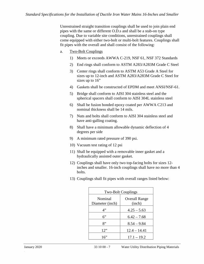
Standard Specifications for the Installation of Ductile Iron Water Mains 16-Inches and Smaller
January 2020 33 10 00 - 7 Water Utility Distribution Piping Materials Ma
Unrestrained straight transition couplings shall be used to join plain end pipes with the same or different O.D.s and shall be a stab-on type coupling. Due to variable site conditions, unrestrained couplings shall come equipped with either two-bolt or multi-bolt features. Couplings shall fit pipes with the overall and shall consist of the following:
a. Two-Bolt Couplings
1) Meets or exceeds AWWA C-219, NSF 61, NSF 372 Standards
2) End rings shall conform to ASTM A283/A283M Grade C Steel
3) Center rings shall conform to ASTM A53 Grade A Steel for sizes up to 12-inch and ASTM A283/A283M Grade C Steel for sizes up to 16”
4) Gaskets shall be constructed of EPDM and meet ANSI/NSF-61.
5) Bridge shall conform to AISI 304 stainless steel and the spherical spacers shall conform to AISI 304L stainless steel
6) Shall be fusion bonded epoxy coated per AWWA C213 and nominal thickness shall be 14 mils.
7) Nuts and bolts shall conform to AISI 304 stainless steel and have anti-galling coating.
8) Shall have a minimum allowable dynamic deflection of 4 degrees per side
9) A minimum rated pressure of 390 psi.
10) Vacuum test rating of 12 psi
11) Shall be equipped with a removable inner gasket and a hydraulically assisted outer gasket.
12) Couplings shall have only two top-facing bolts for sizes 12-inches and smaller. 16-inch couplings shall have no more than 4 bolts.
13) Couplings shall fit pipes with overall ranges listed below:
Two-Bolt Couplings
Nominal Diameter (inch)
Overall Range (inch)
4” 4.25 – 5.63
6” 6.42 – 7.68
8” 8.54 – 9.84
12” 12.4 – 14.41
16” 17.1 – 19.2
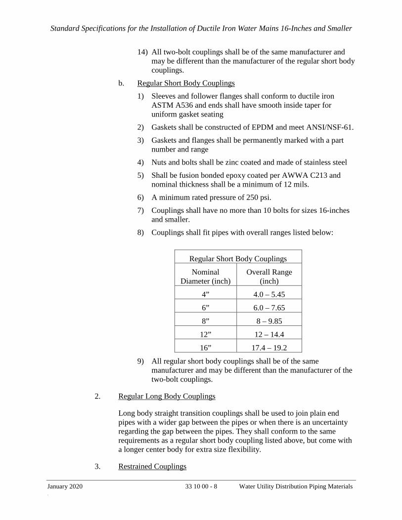
Standard Specifications for the Installation of Ductile Iron Water Mains 16-Inches and Smaller
January 2020 33 10 00 - 8 Water Utility Distribution Piping Materials Ma
14) All two-bolt couplings shall be of the same manufacturer and may be different than the manufacturer of the regular short body couplings.
b. Regular Short Body Couplings
1) Sleeves and follower flanges shall conform to ductile iron ASTM A536 and ends shall have smooth inside taper for uniform gasket seating
2) Gaskets shall be constructed of EPDM and meet ANSI/NSF-61.
3) Gaskets and flanges shall be permanently marked with a part number and range
4) Nuts and bolts shall be zinc coated and made of stainless steel
5) Shall be fusion bonded epoxy coated per AWWA C213 and nominal thickness shall be a minimum of 12 mils.
6) A minimum rated pressure of 250 psi.
7) Couplings shall have no more than 10 bolts for sizes 16-inches and smaller.
8) Couplings shall fit pipes with overall ranges listed below:
Regular Short Body Couplings
Nominal Diameter (inch)
Overall Range (inch)
4” 4.0 – 5.45
6” 6.0 – 7.65
8” 8 – 9.85
12” 12 – 14.4
16” 17.4 – 19.2
9) All regular short body couplings shall be of the same manufacturer and may be different than the manufacturer of the two-bolt couplings.
2. Regular Long Body Couplings
Long body straight transition couplings shall be used to join plain end pipes with a wider gap between the pipes or when there is an uncertainty regarding the gap between the pipes. They shall conform to the same requirements as a regular short body coupling listed above, but come with a longer center body for extra size flexibility.
3. Restrained Couplings

Standard Specifications for the Installation of Ductile Iron Water Mains 16-Inches and Smaller
January 2020 33 10 00 - 9 Water Utility Distribution Piping Materials Ma
Restrained straight transition couplings shall be used to join plain end pipes with the same or different O.D.s and shall be a stab-on type coupling. They shall have a radial gripping system which will provide circular restraint around the pipe and shall consist of the following:
a. Meets or exceeds AWWA C-219, NSF 61, NSF 372 Standards
b. Equipped with top-facing two-bolts
c. End rings shall be made of ductile iron casting and conform to ASTM A536 Grade 60-40-18
d. Center rings shall be made of ductile iron casting and conform to ASTM A536 Grade 65-45-12
e. Gaskets shall be constructed of EPDM and meet ANSI/NSF-61.
f. Grip chain shall consist of gripping teeth and conform to AISI 420 2B
g. Bridge shall conform to AISI 304 stainless steel and the spherical spacers shall conform to AISI 304L stainless steel
h. Shall be fusion bonded epoxy coated per AWWA C213 and nominal thickness shall be 14 mils.
i. Nuts and bolts shall conform to AISI 304 stainless steel and have anti-galling coating.
j. Shall have a minimum allowable dynamic deflection of 4 degrees per side
k. A minimum rated pressure of 350 psi.
l. Vacuum test rating of 12 psi
m. Couplings shall fit pipes with overall ranges listed below:
Restrained Couplings
Nominal Diameter (inch)
Overall Range (inch)
4” 4.40 – 5.10
6” 6.50 – 7.20
8” 8.50 – 9.40
12” 12.68 – 13.39
n. All restrained couplings shall be of the same manufacturer.
4. Stainless Steel Couplings
Stainless steel couplings shall consist of the following:

Standard Specifications for the Installation of Ductile Iron Water Mains 16-Inches and Smaller
January 2020 33 10 00 - 10 Water Utility Distribution Piping Materials Ma
a. Meets or exceeds AWWA C-219, AWWA C-227, NSF-61 and NSF-372 Standards
b. Body and gasket bridge shall comply with AISI 304 Stainless Steel
c. Gaskets shall be constructed of EPDM and meet ANSI/NSF-61.
d. Inner plate shall comply with AISI 304 Stainless Steel connected with reinforced insulated bolts made of Ultern resin 1000 with insert socket set crew AISI 316.
e. Compression beam shall comply with AISI 304 Casting and ASTM-A351-CF8
f. Lugs shall be of polycarbonate for regular pressure or comply with AISI 304 Casting (ASTIM A-351-CF8) for some high pressure pipes
g. Nuts and Bolts shall be rolled thread and anti-galling coating and comply with AISI 304 Stainless Steel
h. Shall have a dynamic deflection of up to 3 degrees per side
i. Shall have a transition capability of up to 0.4”
j. Shall have a working pressure of up to 232 psi for couplings up to 4” and up to 175 psi for couplings up to 16”. Couplings rated for higher pressures shall have a working pressure of up to 232 psi for couplings up to 16”.
k. Rated pressure shall be 1.5 times the working pressure
2.04 GATE VALVES
A. NSF 61 certified gate valves with a design working pressure of 250 psi shall be used for pipe sizes 4 inches and larger. 12-inch and smaller gate valves shall conform to ANSI/AWWA C509. 16-inch gate valves shall conform to ANSI/AWWA C515. All gate valves shall have a non-rising stem and be resilient seated, right turn open, nut (painted red) operated, and fusion-bonded epoxy coated identical to the approved make and model per the current City Purchasing Contract for gate valves. Water main gate valves 12-inches and smaller shall have push-on by push-on (TYTON® joint by TYTON® joint) ends that accommodate FIELD LOK® gaskets. 16-inch water main gate valves shall be mechanical joint ends restrained with EBAA MEGALUG® mechanical joint glands. Flanged end gate valves shall be full-face flange by flange manufactured in accordance with ASA B16.1, 125 lb. Class or ASA B16.2, 250 lb. Class.
2.05 AIR RELEASE AND BLOW-OFF VALVES
A. 2-inch air-release and blow-off valves shall be manual type and the assembly shall be per Standard Plan CDD-LP-003, latest revision.

Standard Specifications for the Installation of Ductile Iron Water Mains 16-Inches and Smaller
January 2020 33 10 00 - 11 Water Utility Distribution Piping Materials Ma
B. Parts for air valve and blow-off valve assemblies shall be by GL Industries, JONES, AY McDonald, Merit Brass, and Mueller.
2.06 CORPORATION STOPS
A. Corporation stops shall be used for service laterals 2-inch and smaller and tap into the main as shown in the Standard Plans CDD-LP-201B and CDD-LP-202B.
2.07 WATER METER BOXES, VAULTS, AND COVERS
A. Meter boxes and covers for standard 1- and 2-inch (domestic) services shall be made of polyethylene and polymer concrete. Meter vaults for services larger than 2-inch shall be fiberglass vaults with torsion assisted frame and cover.
Sizes of meter boxes shall be as shown hereinafter:
Meter Size Nominal Size of Meter Box, Standard Plan(s)
1" 15” x 20" x 12” CDD-LP-213, CDD-LP-208
2" 17" x 30" x 12” CDD-LP-212, CDD-LP-210
Meter Size Nominal Size of Meter Vault, Standard Plan
3” & 4" 36" x 60" x 30" CDD-LP-214
6” 48" x 72" x 30" CDD-LP-215
2.08 HYDRANT, HYDRANT BURY, BREAK AWAY
A. Hydrant should be Long Beach Iron Works Model 621, with valve assembly specified in SFFD specifications for low pressure hydrants. Hydrants shall be painted as required by SFFD. Hydrant and Hydrant Lateral shall be assembled per Standard Plan CDD-LP-004.
2.09 FLANGE GASKETS, NUTS, BOLTS AND WASHERS
A. Flange gaskets
a. All flange gaskets shall be new, type “E”, 1/8 inch thick, and in compliance with ANSI/NSF-61 requirements. Sealing element placement shall accommodate flat faced flanges. The quad-ring seals shall be pressure energized. The G-10 retainer shall have a 550 volts/mil dielectric strength and a minimum 50,000 psi compressive strength. The flange gasket shall be one of the following:
1) Quad-seal, pyrox G-10 material, as manufactured by Advance Products & System, Inc., Part number GETQG10F.

Standard Specifications for the Installation of Ductile Iron Water Mains 16-Inches and Smaller
January 2020 33 10 00 - 12 Water Utility Distribution Piping Materials Ma
2) One full faced isolating and sealing gasket, Linebacker G-10 retainer containing precision tapered grooves to accommodate the controlled compression of EPDM quad-ring sealing elements. Four grooves per gasket.
3) Garlock Multi-Swell 3760U.
b. Outside/inside diameter of the gasket shall be equal to the outside/inside diameter of the flange. Before installation, all gaskets shall require inspection for adherence to the specifications by the City Representative.
B. Nuts, bolts and washers for ductile iron flanges: bolts and nuts for flanged joints shall be stainless steel Type 304 or 316.
2.10 VALVE COVERS AND VALVE BOX
A. Valve covers, valve boxes, steel base plates, ductile iron riser pipes, and miscellaneous metals as required for valve box assemblies shall be as specified in Standard Plan CDD-LP-250, latest revision.
2.11 BACKFLOW PREVENTER
A. All backflow prevention assemblies must have a maximum working pressure of 175 pounds per square inch (psi) and must be on the “Approved Backflow Prevention Assemblies” list developed by the University of Southern California (USC) Foundation for Cross-Connection Control and Hydraulic Research (FCCCHR).
B. All backflow prevention assemblies and associated pipe, fittings, solder and flux must be “lead-free” as defined in the California Health and Safety Code, Section 116875.
C. Any modification of an assembly—such as relocation of valves, bypass arrangements, and jumper connections, whether temporary or permanent—invalidates the foundation’s approval and is not permitted. Likewise, an assembly that has been installed in an orientation for which it was not designed or approved is also not permitted.
D. Backflow prevention assemblies must be inspected per the requirements of the SFPUC Cross Connection Control program prior to connection service connection into the SFPUC water distribution system.
END OF SECTION

Standard Specifications for the Installation of Ductile Iron Water Mains 16-Inches and Smaller
January 2020 33 11 00 - 1 Installation of 16-Inch and Smaller Water Mains and Appurtenances
SECTION 33 11 00
INSTALLATION OF 16-INCH AND SMALLER WATER MAINS AND APPURTENANCES
PART 1 – GENERAL
1.01 WORK INCLUDED
A. Work under this Section includes installation of all necessary components complete in place to provide a functional potable water distribution system, in accordance with all the requirements as specified herein and as shown in the contract plans, including, but not limited to the following:
B. Installation of 4-, 6- and 8-inch U.S. Pipe Tyton joint ductile iron pipe and fittings with Field Lok gaskets
C. Installation of 12- and 16-inch American Flex-Ring joint ductile iron pipe and fittings with Fastite gaskets.
D. Installation of flanged joint ductile iron pipe and fittings.
E. Installation of 4-, 6-, 8- 12-inch Tyton joint gate valves with Field Lok gaskets.
F. Installation of 16-inch mechanical joint gate valves with EBAA Megalug mechanical joint restraints.
G. Installation of 2-inch air and blow off valves.
H. Installation of valve boxes and valve box covers.
I. Assembly and installation of 4- and 6-inch flushing assemblies.
J. Temporary and permanent piping support and bracing systems including thrust blocks.
K. Cleaning and hydrostatic testing of ductile iron pipe.
L. Coordinating and providing support for SFPUC-CDD work.
1.02 RELATED SECTIONS
A. Section 31 23 36 – Excavation and Backfill
B. Section 33 10 00 – Water Utility Piping materials
C. Section 33 11 41 – V-Bio Polyethylene Encasement of Ductile Iron Pipe

Standard Specifications for the Installation of Ductile Iron Water Mains 16-Inches and Smaller
January 2020 33 11 00 - 2 Installation of 16-Inch and Smaller Water Mains and Appurtenances
D. Section 33 13 00 – Sanitary Work Practices and Disinfection of Water Utility Distribution
1.03 REFERENCES
A. ANSI/ASME B 18.2.1 – Square and Hex Bolts and Screws; and Hex Cap Screws and lag Screws
B. ANSI/ASME B 18.2.2 – Square and Hex Bolts (Inch Series)
C. ANSI/ASME B 1.1 – Unified Inch Screw Threads
D. ANSI/NSF-61 – Drinking Water System Components
E. ASTM A193 or A194 Type 304 or 316
F. AWWA C104 – Cement-Mortar Lining for Ductile-Iron Pipe and Fittings
G. AWWA C110 – Ductile-Iron and Gray-Iron Fittings
H. AWWA C111– Rubber Gasket Joints for Ductile-Iron Pressure Pipe and Fittings
I. AWWA C115 – Flanged Ductile-Iron Pipe with Ductile-Iron or Gray-Iron Threaded Flanges
J. AWWA C153 – Ductile-Iron Compact Fittings
K. AWWA C509 – Resilient-Seated Gate Valves for Water Supply Service
L. AWWA C600 – Installation of Ductile Iron Water Mains and Their Appurtenances
M. San Francisco Public Works Standard Specifications (latest version)
N. SFPUC-CDD Standard Plans
O. California Code of Regulations, Title 22, CA DPH
P. SFPUC Asset Protection Standards, May 2017 or latest revision
1.04 HANDLING AND DELIVERY MATERIALS
A. The Contractor shall provide all labor, equipment and transportation means required to provide materials to the jobsite. Piping materials and appurtenances shall be stored in a manner safe to the public and in accordance with the local agency requirements.
B. During loading, transportation and unloading, every precaution shall be taken to prevent damage to the material. Under no circumstances shall the pipe, fittings

Standard Specifications for the Installation of Ductile Iron Water Mains 16-Inches and Smaller
January 2020 33 11 00 - 3 Installation of 16-Inch and Smaller Water Mains and Appurtenances
and appurtenances be dropped or skidded against each other. Slings, hooks or pipe tongs shall be padded and used in such a manner as to prevent damage to the exterior surface or internal lining of the pipe.
C. Repair damaged coating and/or cement mortar lining to match quality, thickness and bonding of original in accordance with manufacture’s requirement and AWWA standards. When coating and/or lining cannot be repaired or repairs are defective, replace piping material with undamaged one. The entire cost to repair or replace these materials shall be borne by the Contractor.
D. The Contractor shall store fittings and other accessories such that they do not accumulate and hold rainwater, dirt and debris. Gaskets shall be protected from long term exposure to sunlight. Openings in pipes shall be capped or plugged with removable plastic plugs or caps to prevent dirt and other foreign matter from entering the system. Plugs of rags, wood, cotton, waste or similar materials shall not be used. All piping materials shall be stored away from standing water.
1.05 SUBMITTALS
A. Pipe Shop Drawings
1. Contractor shall survey street grade and pothole to locate existing underground utilities. The new ductile iron pipe alignment shall be developed based on this information. Contractor shall be responsible for developing the alignment of the new pipeline with the incorporation of information found from the field survey and potholing.
2. Shop drawings shall show the pipe stationing and invert elevations at all changes in grade and horizontal alignment
3. Shop drawings shall include each pipe piece, fitting, valve, connection to existing pipes and other appurtenances.
4. Contractor shall submit the shop drawings and detailed installation drawings for approval prior to ordering materials for construction. The approval of shop drawings does not relieve the Contractor from the responsibility to furnish and install appropriate pipe pieces, fittings and appurtenances to successfully install the potable water distribution system. There will be no time extension for ordering and procuring materials.
B. Catalog cut sheets of all materials to be furnished by the Contractor.
C. Manufacturer’s approved installation instruction including field cut joint assembly procedures.
D. Hydrostatic Test Plan
E. Schedule

Standard Specifications for the Installation of Ductile Iron Water Mains 16-Inches and Smaller
January 2020 33 11 00 - 4 Installation of 16-Inch and Smaller Water Mains and Appurtenances
1. The contract time allowance includes the time for the San Francisco Water Department (SFPUC-CDD) personnel to complete their work as specified herein after. The Contractor shall incorporate the SFPUC-CDD required times in his/her schedule. The Contractor shall confer with the City Representative in the preparation of the schedule that needs to satisfy the water distribution operation and minimize disruption of the services. No construction for water work shall be started until the City Representative approves the schedule.
2. The time required by SFPUC-CDD to complete each type of work is listed below per pipe segment.
a. Request for pipeline connection measurement:
i. Main connections and services larger than 2-inch diameter pipe require SFPUC-CDD to perform measurements for pipeline fabrication prior to any main connection or service change over.
ii. Contractor is required to complete the required excavation and shoring prior to SFPUC-CDD performing the requested connection measurement. In the event the excavation size does not conform to paragraph 31 23 36 3.12.G or as directed by the City Representative or the excavation is not adequately shored, the Contractor will be required to perform the requested corrections prior to submitting a new request for measurement. The Contractor shall be responsible for any delays associated with performing the subject corrective work and additional connection measurements. The Contractor will be back charged all labor, equipment, and materials associated with SFWD mobilizing more than two times for same connection request.
iii. 2 working days from the time connection measurement is requested by Contractor through the City Representative to completion of measurement by SFPUC-CDD.
iv. For 12-inch and smaller pipes, up to four measurements per request can be submitted, provided that measurements are:
A) All are either for services larger than 2-inch diameter pipe (excluding services with manifold meters) or for main connections, and
B) All within the same pipe segment, and
C) All within the same main shutdown.
v. For 16- and 24-inch pipes, up to two measurements can be requested provided that measurements are:
A) All main connections, and
B) All within the same pipe segment, and

Standard Specifications for the Installation of Ductile Iron Water Mains 16-Inches and Smaller
January 2020 33 11 00 - 5 Installation of 16-Inch and Smaller Water Mains and Appurtenances
C) All within the same main shutdown.
b. Connection to an active main:
i. Flushing and Chlorinating connection (the first connection of a segment of pipe). A) 14 working days from the time SFPUC-CDD completes
connection measurements (for 12-inch or smaller diameter pipe).
B) 21 working days from the time SFPUC-CDD completes connection measurements (for 16-inch or larger diameter pipe).
ii. Main connection:
A) 14 working days from the time SFPUC-CDD completes all connection measurements for a main connection request up to four connections or 20 working days for up to eight connections (for 12-inch and smaller diameter pipe within the same pipe segment).
B) 21 working days from the time SFPUC-CDD completes connection measurements for up to two main connections (for 16-inch or larger diameter pipe within the same pipe segment).
Note: When a request involves multiple connections within the same main shutdown, SFPUC-CDD will not make any connection to an active main until all connection measurements in that request are completed.
c. Chlorination including sampling and laboratory testing
i. 5 working days from the time the flushing and chlorinating connection is made.
ii. Chlorination is required for the first main connection (flushing and chlorinating connection) of each segment. The remaining main connections in a chlorinated segment do not require chlorination.
d. Service change over and hydrant set request:
i. Service connections and hydrant set shall only be made to an approved chlorinated segment of pipe that has passed required water quality testing by SFPUC-CDD. Hydrant set can be requested independently from service change over. However, if a hydrant lateral is required to be connected to a chlorinated segment of pipe, a request shall be made as large service change over per subparagraph v.C). (Service larger than 2 inches in diameter).

Standard Specifications for the Installation of Ductile Iron Water Mains 16-Inches and Smaller
January 2020 33 11 00 - 6 Installation of 16-Inch and Smaller Water Mains and Appurtenances
ii. Contractor shall only request the same service change over type for each working day per the above schedule. Requests for a combination of service change over types for the same working day shall be subject to approval by the City Representative.
iii. The Contractor shall provide all required labor, equipment, and materials to support service renewals including completing required excavation and shoring along with providing required traffic control and materials to perform the work. The above working durations are based on the Contractor completing the required advance preparation work along with providing adequate support.
iv. All services shall be changed over before remaining main connections (non-flushing and chlorinating connections) can be made within the same pipe segment. Service change over and main connections will not be installed simultaneously.
v. Service Renew or Retap A) 1-inch services. • 1 working day for up to 8 retap (RT) services. • 1 working day for up to 8 short renew (RN) services. • 1 working day for up to 4 long renew (RN). B) 2-inch services. • 1 working day for up to 4 retap (RT) services. • 1 working day for up to 3 short renew (RN) services. • 1 working day for up to 2 long renew (RN) services.
C) Services larger than 2 inches in diameter • 10 working days from the time SFPUC-CDD completes
measurements for each replacement of a manifold meter. • 10 working days from the time SFPUC-CDD completes
measurements for up to four services or 15 working days for up to eight services (without replacement of manifold meters) within the same pipe segment.
3. The Contractor shall notify the City Representative in writing three weeks before any work by SFPUC-CDD personnel is required and confirm with the City Representative 72 hours (3 working days) before the actual work is required on the field. The Contractor shall complete the excavation of the water main connection pit and install appropriate shoring to the satisfaction of the City Representative before SFPUC-CDD personnel can do any work.
4. Contractor shall use the table below to identify pipe segments and develop the construction schedule for approval (example shown).

Standard Specifications for the Installation of Ductile Iron Water Mains 16-Inches and Smaller
January 2020 33 11 00 - 7 Installation of 16-Inch and Smaller Water Mains and Appurtenances
SEGMENT CHLORINATION INTERSECTION
FLUSHING ASSEMBLY INTERSECTION
NO. OF CONN. AND DISCONN.
1 7th St and Townsend St 7th St and Mission Bay St 10 2 7th St and Townsend St 7th St and 16th St 6
F. Field Welding
1. If field welds are required during construction, the Contractor shall submit the following:
a. Welding Procedure Specification (WPS), which shall address the equipment, materials and instructions how the work shall be performed;
b. Welder Performance Qualification for each welder, which shall demonstrate that the welder has satisfactorily performed work regarding the specific materials, welding process, test position, etc., listed under the Welding Procedure Specification (WPS); and
c. Certified Welding Inspector (CWI) Certification from the American Welding Society (AWS) for each welding inspector indicating that the welder to perform the work is accredited by national standards.
G. Slurry fill
1. Work Plan for slurry filling abandoned mains greater than 8 inches.
2. Mix design for slurry.
3. 28-day compressive strength of the slurry.
1.06 SUPPORT WORK
A. The Contractor shall provide traffic control, removal and resetting of steel plates and general housekeeping as requested by the City Representative for all main connection measurements, disinfections, main connection operations and service connections by SFPUC-CDD. This will be considered incidental work and no additional payment will be made therefore except for traffic control, which shall be paid through the Bid Item for Traffic Control.
1.07 QUALITY ASSURANCE
A. Inspection: Installation of all piping materials and appurtenances shall be subject to inspection by the City Representative, in accordance with the provisions of the referenced standard, as supplemented by the requirements herein. Inspection of pipe materials and appurtenances will be made by the City Representative after delivery. All materials and their installation shall be subject to rejection at any time on account of failure to meet any of the specified requirements.

Standard Specifications for the Installation of Ductile Iron Water Mains 16-Inches and Smaller
January 2020 33 11 00 - 8 Installation of 16-Inch and Smaller Water Mains and Appurtenances
B. City Representative may request support work at night. The Contractor’s additional costs associated with the difference in standard and overtime for support work associated with SFPUC-CDD activities outside of normal working hours shall be paid through the Allowance Bid Item for Working Outside Normal Work Hours. Additional requests for support work at night at the same location will be compensated as time and material.
C. Night Noise Permit
2. If SFPUC night work is required, the Contractor shall obtain the night noise permit on behalf of SFPUC-CDD. SFPUC-CDD will provide the affidavit, mailing list and flyer for the permit application.
3. The durations set forth in Part 1 of this specification section does not include time to obtain night noise permits. No additional time will be given to obtain night noise permits.
D. Contractor shall provide a certified welding inspector to inspect all field cut welds. Welding shall be performed in accordance with the provisions of US Pipe field welding instructions (where TR Flex pipe joints are being installed).
1.08 WARRANTY
A. The Contractor shall furnish a two (2) year warranty for all work covered by this Section.
PART 2 – PRODUCTS
2.01 DUCTILE IRON PIPE MATERIALS
A. Contractor shall furnish all materials necessary to complete pipeline construction. This includes all pipe, fittings, valves, gaskets, nuts and bolts, tools, and other materials necessary to complete construction as specified in section 33 10 00 Water Utility Piping Materials. Materials to be furnished shall be approved by SFPUC-CDD prior to their purchase by the contractor.
B. The Contractor shall field verify the lengths at the time of construction, and furnish all the necessary pipe pieces, pipe appurtenances and material to complete the installation.
C. The Contractor is advised to thoroughly inspect all materials supplied by the manufacturer prior to acceptance of such materials. Materials found to be damaged shall be repaired or replaced as directed by the City Representative. The entire cost to repair or replace these materials shall be borne by the Contractor.

Standard Specifications for the Installation of Ductile Iron Water Mains 16-Inches and Smaller
January 2020 33 11 00 - 9 Installation of 16-Inch and Smaller Water Mains and Appurtenances
PART 3 – EXECUTION
3.01 INSTALLATION OF DUCTILE IRON PIPE AND FITINGS
A. Before any pipe may be installed, the grade of the trench bottom shall be approved by the City Representative. Immediately prior to installing the pipe, the Contractor shall remove all loose rocks and other objectionable material from the bottoms of the trench and bell holes. When the trench is properly prepared, the pipe shall be lowered therein, singly, without jarring or strain and joined to each adjoining pipe section in accordance with the manufacturer’s recommendations.
B. Pipe trench widths and trench depths shall be as specified in SFPUC-CDD Standard Plans, latest revision. Pipe may be installed deeper than the trench depth prescribed in the SFPUC Standard Plans only when necessary to avoid subsurface obstacles and when approved by the City Representative.
C. The City requires that water mains with less than the minimum cover have a protecting slab or other structural protective measures. In addition, such alternate design shall require approval, on a case-by-case basis by SFPUC-CDD.
D. Restrained joints for ductile iron pipe and fittings shall be assembled per manufacturer’s written installation instructions. The deflection at joints shall not exceed 2 degrees or 40 percent of maximum allowable deflection permitted by the manufacturer, whichever is less, and the bending radius shall be 300 feet minimum. Joint restraint devices shall be per SFPUC-CDD Standard Plans. Bolts, nuts, and tie-rods shall be stainless steel type 304 or 316.
E. Pipe Restraints
1. Restrainers and tie-rod joint restraints shall be installed at specified locations, as additional lugs/restrainers and tie-rods may be required by the City Representative if deemed necessary.
2. Restraint of field cut Flex-Ring® and TR FLEX® pipe shall be prepared as per manufacturer’s field cutting and welding procedure. Any damage to the lining and coating shall be repaired to the satisfaction of the City Representative.
3. Additional restraints required in addition to joint restraint by pipe manufacturer (see also Standard Plan CDD-LP-006):
a. General
1) Tie-rod restraint shall be installed on TYTON® joints with FIELD LOK® gaskets at the following situations to provide double safety. No tie-rod is required for flanged joints. A) First valve on a tee branch from a run.

Standard Specifications for the Installation of Ductile Iron Water Mains 16-Inches and Smaller
January 2020 33 11 00 - 10 Installation of 16-Inch and Smaller Water Mains and Appurtenances
B) All joints within 26 feet upstream of an opened end (normally terminated with a cap or a valve for future connections; or a hydrant or blow-off valve outlet).
b. Fitting Bells with TYTON® Joints
1) Fitting bells and tees with two cast-in restraining lugs, with 7/8-inch diameter holes. Attach the ¾-inch tie-rod to the cast-in restraining lugs with nuts and washers to provide the restraint to bells.
c. Pipe Bells with TYTON® Joints
1) Pipe bells do not have lugs cast into the bell. Restrainers that take the bearing on the back of the pipe bell shall be used to provide the attachment point, referred hereafter as “Pipe Bell Restrainer.” Size and number of tie-rods shall be as per the restrainer’s manufacturer to restrain the test pressure.
2) Bell restraint harness may also be used.
d. Plain End Pipe with TYTON® Joints
1) Restrainer with the wedge action on the pipe to provide the attachment point shall be used with all gate valves and will be referred herein after as “Plain End Restrainer”. Restraint harness may also be used if approved by the City Representative.
2) To restrain a fitting bell with restraining lugs to a Plain End Restrainer, use two ¾-inch tie-rods.
3) To restrain a Bell Restrainer to a Plain End Restrainer, the same quantity and size of tie-rods as required by the manufacturer to resist the test pressure shall be used.
4) To restrain a Plain End Restrainer to another Plain End Restrainer, the same quantity and size of the tie-rods as recommended by the manufacturer to resist the test pressure shall be used.
F. The assembly for cut pipe to bell shall be completed as described for full-length pipe and per manufacturer instructions. Care should be taken to ensure that all corners are rounded and no sharp edges remain that might damage or dislodge the gasket. Any damage to the lining or coating shall be repaired to the satisfaction of the City Representative.
G. If the joint assembly is not accomplished with the application of reasonable force, the plain end of the pipe should be removed to check the proper position of the gasket. Care shall be exercised to protect the pipe laid from any foreign materials or obstructions entering the pipe. At the end of each day, the Contractor shall, to

Standard Specifications for the Installation of Ductile Iron Water Mains 16-Inches and Smaller
January 2020 33 11 00 - 11 Installation of 16-Inch and Smaller Water Mains and Appurtenances
the satisfaction of the City Representative, plug or cover the open end of the pipe laid.
H. As the pipe is being installed a minimum of 75 feet shall be maintained between the end of the new pipeline and the end of the trench being excavated (except where trenching reached the end of the design alignment) or from any visible obstructions. The purpose of this stipulation is to permit the City Representative to see in advance whether any horizontal or vertical adjustments in the pipe alignment will be required to avoid conflicts.
I. Temporary Blowoffs and Flushing Assemblies
4. Contractor shall coordinate with the City Representative prior to the installation of temporary blowoffs or the flushing assembly in a segment. One flushing assembly is required at the end of each segment as shown in the drawings and temporary blowoffs are required at all remaining open ends of the segment. Flushing assemblies may be required at more than 1 location if so determined by the City Representative.
5. Flushing assembly shall be installed in accordance with SFPUC CDD Standard Plan CDD-LP-005.
J. TYTON® Joint Pipe
1. Tyton joints for ductile iron pipe and gate valves shall be restrained by use of FIELD LOK® gaskets unless otherwise directed by the City Representative.
2. Any foreign matter in the socket shall be removed prior to installing the gasket; the gasket seat shall be thoroughly inspected to be certain it is clean. The gasket shall be wiped clean, flexed and then placed in the socket with the large round end entering first so that the gasket is seated evenly around the inside of the socket with the heel of the FIELD LOK® gasket or other approved gaskets fitting snugly in the retainer seat. Looping the gasket will facilitate inserting the gasket. A thin film of lubricant shall be applied with a paintbrush to the exposed surface of the gasket. The last 6 or 8 inches of the pipe shall be thoroughly cleaned before applying a thin film of lubricant to the outside of the plain spigot to a line about one inch back from the end. The pipe spigot shall not be allowed to touch the ground or trench side after it is lubricated. Lubricant other than that furnished with the pipe shall be used. The spigot end of the pipe shall be aligned and carefully started into the socket until it just makes contact with the gasket. Joint assembly shall then be completed by forcing the spigot end of the pipe past the gasket until the inside edge of the first painted strip or the spigot end of full-length pipe is approximately flush with the bell face. The deflection of the joint shall be done after this. The pipe shall then be moved in the opposite direction to lock the joint.
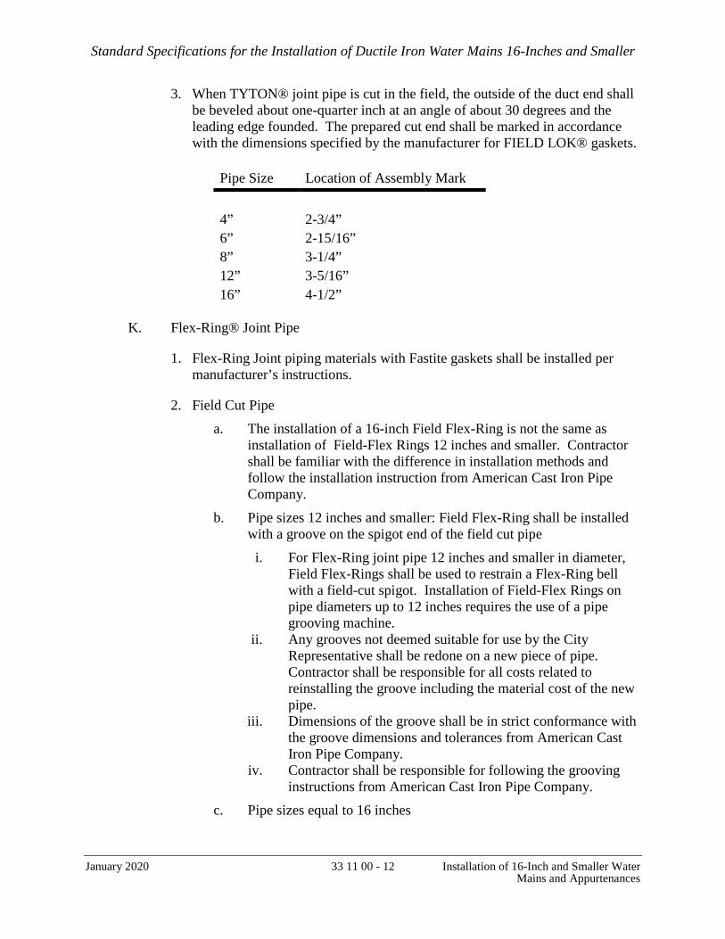
Standard Specifications for the Installation of Ductile Iron Water Mains 16-Inches and Smaller
January 2020 33 11 00 - 12 Installation of 16-Inch and Smaller Water Mains and Appurtenances
3. When TYTON® joint pipe is cut in the field, the outside of the duct end shall be beveled about one-quarter inch at an angle of about 30 degrees and the leading edge founded. The prepared cut end shall be marked in accordance with the dimensions specified by the manufacturer for FIELD LOK® gaskets.
Pipe Size
Location of Assembly Mark
4”
2-3/4”
6” 2-15/16” 8” 3-1/4” 12” 3-5/16” 16” 4-1/2”
K. Flex-Ring® Joint Pipe
1. Flex-Ring Joint piping materials with Fastite gaskets shall be installed per manufacturer’s instructions.
2. Field Cut Pipe
a. The installation of a 16-inch Field Flex-Ring is not the same as installation of Field-Flex Rings 12 inches and smaller. Contractor shall be familiar with the difference in installation methods and follow the installation instruction from American Cast Iron Pipe Company.
b. Pipe sizes 12 inches and smaller: Field Flex-Ring shall be installed with a groove on the spigot end of the field cut pipe
i. For Flex-Ring joint pipe 12 inches and smaller in diameter, Field Flex-Rings shall be used to restrain a Flex-Ring bell with a field-cut spigot. Installation of Field-Flex Rings on pipe diameters up to 12 inches requires the use of a pipe grooving machine.
ii. Any grooves not deemed suitable for use by the City Representative shall be redone on a new piece of pipe. Contractor shall be responsible for all costs related to reinstalling the groove including the material cost of the new pipe.
iii. Dimensions of the groove shall be in strict conformance with the groove dimensions and tolerances from American Cast Iron Pipe Company.
iv. Contractor shall be responsible for following the grooving instructions from American Cast Iron Pipe Company.
c. Pipe sizes equal to 16 inches

Standard Specifications for the Installation of Ductile Iron Water Mains 16-Inches and Smaller
January 2020 33 11 00 - 13 Installation of 16-Inch and Smaller Water Mains and Appurtenances
i. For pipe diameters 16 inches and larger, Field Flex-Rings shall be used to restrain a bell joint with a field cut pipe in lieu of a standard Flex-Ring joint spigot with a factory welded-on ring.
d. When Flex-Ring joint pipe is cut in the field, the outside of the plain end shall be beveled about 3/8” to 5/8” long at an angle of about 30 to 40 degrees with the axis of the pipe. All sharp corners or rough edges that might damage or dislodge the Fastite gasket or Field Flex-Ring should be removed from the beveled pipe end. The prepared cut end shall be marked in accordance with the dimensions specified by the manufacturer for Fastite gaskets.
3. Flex-Ring Pipe and Fitting sockets allow a small amount of axial movement which provides substantial flexibility after installation. Unwanted expansion shall be prevented by manually pulling the pipe to full extension after installing the locking ring and prior to setting the joint deflection to minimize joint take-up in test or service conditions. In any application where axial or lateral movement may be undesirable, such as certain bridge crossings, certain exposed or unburied piping applications, or certain connections of restrained pipe sections to rigid piping, special provisions, including effective joint extension, may be necessary to control unacceptable pipeline movement.
4. The correct positioning of the yellow Flex-Ring or yellow restraining segments (if pipe diameter larger than 12 inches) in the socket locking groove shall be verified by visual or physical inspection.
5. For field-cut Flex-Ring pipe, spigot assembly stripes shall be located as shown in the table below. The dimensions in the table are not to be confused with the dimensions for grooving a Field Flex-Ring.
Pipe Size
Location of Assembly Mark
4”
5.49”
6” 5.49” 8” 5.61” 12” 6.59” 16” 7.25”
L. TR Flex® Joint Pipe
1. TR FLEX® piping materials with TYTON® gaskets shall be installed per manufacturer’s instructions.
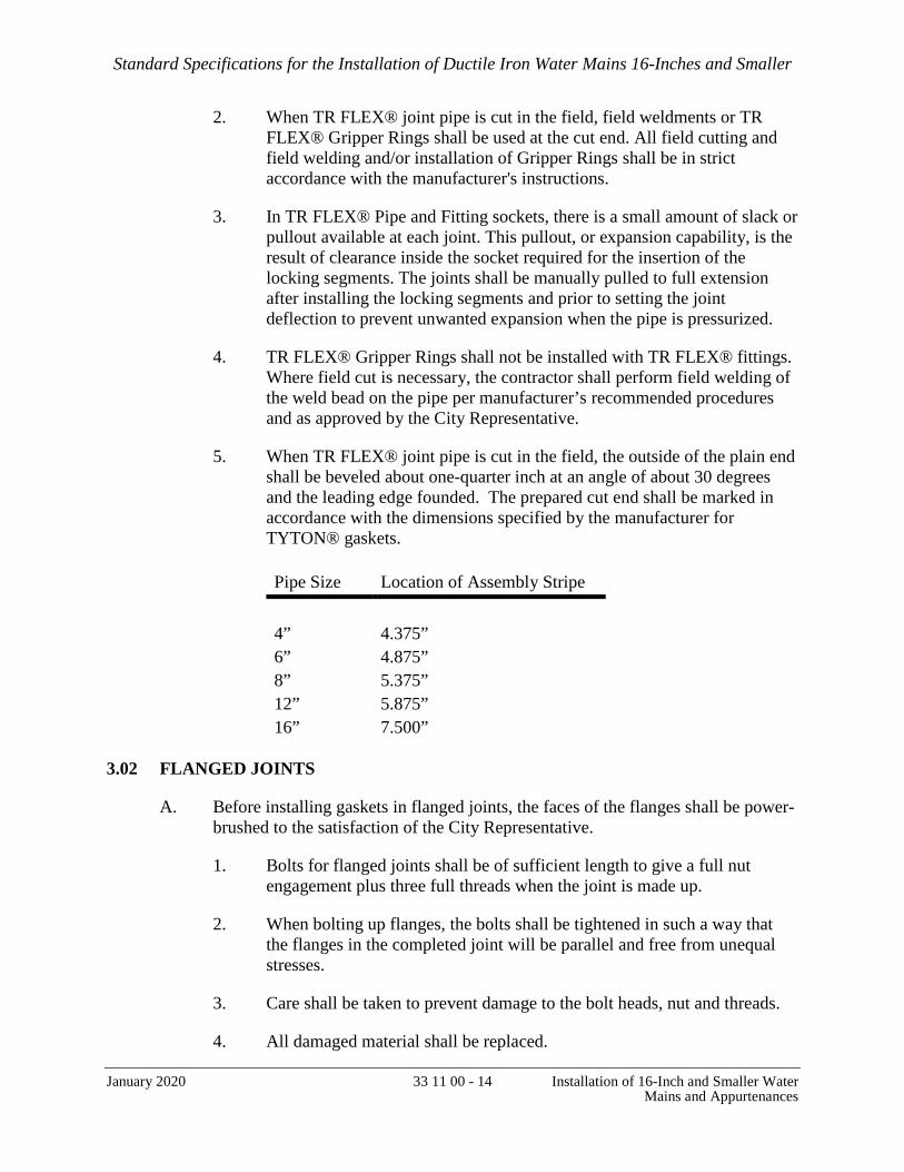
Standard Specifications for the Installation of Ductile Iron Water Mains 16-Inches and Smaller
January 2020 33 11 00 - 14 Installation of 16-Inch and Smaller Water Mains and Appurtenances
2. When TR FLEX® joint pipe is cut in the field, field weldments or TR FLEX® Gripper Rings shall be used at the cut end. All field cutting and field welding and/or installation of Gripper Rings shall be in strict accordance with the manufacturer's instructions.
3. In TR FLEX® Pipe and Fitting sockets, there is a small amount of slack or pullout available at each joint. This pullout, or expansion capability, is the result of clearance inside the socket required for the insertion of the locking segments. The joints shall be manually pulled to full extension after installing the locking segments and prior to setting the joint deflection to prevent unwanted expansion when the pipe is pressurized.
4. TR FLEX® Gripper Rings shall not be installed with TR FLEX® fittings. Where field cut is necessary, the contractor shall perform field welding of the weld bead on the pipe per manufacturer’s recommended procedures and as approved by the City Representative.
5. When TR FLEX® joint pipe is cut in the field, the outside of the plain end shall be beveled about one-quarter inch at an angle of about 30 degrees and the leading edge founded. The prepared cut end shall be marked in accordance with the dimensions specified by the manufacturer for TYTON® gaskets. Pipe Size
Location of Assembly Stripe
4”
4.375”
6” 4.875” 8” 5.375” 12” 5.875” 16” 7.500”
3.02 FLANGED JOINTS
A. Before installing gaskets in flanged joints, the faces of the flanges shall be power-brushed to the satisfaction of the City Representative.
1. Bolts for flanged joints shall be of sufficient length to give a full nut engagement plus three full threads when the joint is made up.
2. When bolting up flanges, the bolts shall be tightened in such a way that the flanges in the completed joint will be parallel and free from unequal stresses.
3. Care shall be taken to prevent damage to the bolt heads, nut and threads.
4. All damaged material shall be replaced.

Standard Specifications for the Installation of Ductile Iron Water Mains 16-Inches and Smaller
January 2020 33 11 00 - 15 Installation of 16-Inch and Smaller Water Mains and Appurtenances
5. Flanged joints showing leaks will not be acceptable.
6. Leaks shall be stopped by one or all of the following methods, cleaning flange face; replacement of gaskets, and adjustment of tension on bolts. No other method will be permitted.
7. Where, in the opinion of the City Representative, conditions prevent the use of hex head bolts, stud bolts of the proper size shall be substituted.
3.03 THRUST BLOCKS
A. Thrust blocks shall be installed at hydrant and hydrant laterals, blow offs and other locations as shown on the Contract Drawings or per SFPUC-CDD Standard Plans. The concrete shall be poured against a satisfactory bearing surface and be of sufficient size to prevent any movement of the pipeline when subjected to the hydrostatic test pressure.
3.04 INSTALLATION OF HYDRANTS
A. Location of fire hydrants shall be as required by SFFD and as shown on the approved plans.
B. Hydrants shall be installed near the street curb, and shall be accessible to fire trucks, and protected from traffic. Hydrants shall be located at a distance of 24” minimum and 27” maximum from the face of curb to center of the hydrant, and at least five (5) feet from a utility pole, traffic control box, or fixed object or structure. Hydrants shall not be installed with curb return areas or in sidewalk areas serving crosswalks.
C. In addition to FIELD LOK® gaskets or other type of restrained joints, all joints on hydrant laterals shall be restrained as shown on SFPUC-CDD Standard Plans.
D. Contractor shall install hydrant laterals, valves, hydrant buries, and risers. SFPUC-CDD will install breakaways and hydrants at the cost of the Contractor.
3.05 INSTALLATION OF VALVES AND VALVE BOXES
A. GATE VALVES
1. Gate valves shall be located on all branches of the main including services that are 4-inches or larger. Each fire hydrant shall be provided with an isolating valve. An additional gate valve shall be installed next to the main if the hydrant lateral is longer than 20 feet. On long distribution mains, valves shall be installed at every 500 feet in commercial areas and no more than one block apart or within an interval of 800 feet in other areas. Dead ends for future expansion shall be provided with a gate valve and a blow-off valve. All taps to existing mains shall be provided with valves.

Standard Specifications for the Installation of Ductile Iron Water Mains 16-Inches and Smaller
January 2020 33 11 00 - 16 Installation of 16-Inch and Smaller Water Mains and Appurtenances
2. Valves on service pipes 2-inch or less shall be “corporation stop” type and buried.
B. AIR RELEASE AND BLOW-OFF VALVES
1. Air release valves shall be installed next to a shut-off valve and at the high points in the distribution system isolated by two gate valves.
2. Blow-offs shall be installed at dead ends and at low points in the distribution system isolated by two gate valves.
3. When installed as a set, center to center spacing between the air release valve and blow-off valve to the gate valve shall be 3 feet. The first air release valve/blow-off valve shall not be more than 3 feet behind the property line (typically in line with the crosswalk striping at the intersection).
4. The air release valve/blow-off valve and gate valve shall not be under sidewalks, reinforced concrete bus pads, bulb-outs or concrete gutters and crosswalk areas.
C. VALVE BOXES & COVERS
1. Over each buried valve, or other similar appurtenance, a piece of ductile iron pipe of such size shall be placed vertically to form a valve box. A suitable cover shall be placed on top of the pipe or box. The bottom of the box shall rest on a steel plate furnished by the SFPUC-CDD so placed as to prevent the box from bearing on the buried devices. Steel plates supporting boxes, over valves shall be set on an asphalt bed. Contractor shall cut the box to such lengths that the top of the gate cover will be flush with the surface of the finished pavement or as shown on the Contract Drawings. Valves boxes for 16-inch and smaller gate valves shall be furnished by the City and installed by the Contractor.
3.06 INSTALLATION OF BACKFLOW PREVENTER
A. All backflow prevention assemblies must be located as close as possible/practical to the water meter or point of connection (POC) but in no case more than 25 feet from the POC. If any part of a service line extends over bay or ocean waters, assemblies must be installed upstream of the seawall (and within 25 feet of the POC).
B. Assemblies must be installed in the orientation intended by the manufacturer and approved by the USC FCCCHR. An assembly that was designed and approved for horizontal installation must not be installed vertically, and vice versa.
C. Required clearances:

Standard Specifications for the Installation of Ductile Iron Water Mains 16-Inches and Smaller
January 2020 33 11 00 - 17 Installation of 16-Inch and Smaller Water Mains and Appurtenances
1. Minimum 12 inches above ground or floor.
2. Minimum 12 inches from each side.
3. If an assembly is installed 5 feet or more above the finished floor/ground, a platform approved by CALOSHA (California Occupational Safety and Health Administration) must be used for testing/serving by testers or contractors. The platform may be permanent or portable.
D. The backflow prevention assembly must be installed so that its make and serial number are visible in a readily accessible location. These identifiers must not be painted over or otherwise made illegible.
E. Assemblies may not be installed in pits or vaults in the ground.
F. If an enclosure is used, the enclosure must be large enough or removable to allow for testing/servicing.
G. No water connections may be between the POC and a backflow prevention assembly.
H. When a reduced pressure principle assembly is installed, a drain funnel must also be installed to prevent flooding.
I. If the domestic service does not require a separate backflow prevention assembly, the supply line to fire sprinklers must tee off the domestic service such that the distance from the center of the domestic tee to the inlet of the backflow prevention assembly does not exceed 12 inches.
J. WQD must confirm installation of the required backflow prevention assembly(ies) before CDD will install the service line.
K. For non-fire service, after installing the service line, (CDD) flushes the service line to the point of connection and installs the water meter.
L. For fire service, contractors must contact CDD to arrange for flushing of the service line. After the service line has been flushed, contractors must call the SFPUC Cross-Connection Control Program at (650) 652-3199 or [email protected] to arrange for installation of the red-top water meter.
M. Backflow prevention assemblies must be tested upon first water turn-on, annually thereafter, and whenever they are relocated, reoriented, or repaired. Testers must have a valid Permit to Operate issued by the San Francisco Department of Public Health. The tester must submit the test reports to the Cross-Connection Control Program within five calendar days of the test date.
Standard Specifications for the Installation of Ductile Iron Water Mains 16-Inches and Smaller
January 2020 33 11 00 - 18 Installation of 16-Inch and Smaller Water Mains and Appurtenances
3.07 PIPE MARKING
A. The Contractor shall provide and install buried non-detectable warning tape in trench, continuously over the centerline of the pipe, as per Section 31 23 36 – Excavation and Backfill and SFPUC-CDD Standard Plans.
3.08 IDENTIFICATION OF RESTRAINED GASKET JOINTS
A. The Contractor shall identify all joints by spraying white marking paint on top of each bell and also by taping a direct burial tape around the spigot end of each pipe, just in front of the bell. The Contractor shall provide paint and tape.
3.09 CLOSING OF UNINSPECTED WORK
A. The Contractor shall not cover, or allow to be covered, any of the work installed under this Contract before it has been inspected and approved by the City Representative. Should any of the work be covered prior to such approval, the City Representative shall have the authority to require the work to be uncovered for inspection and approval, recovered, and all resultant damage required, all at the Contractor’s expense (also refer to Article 8 of the General Conditions).
3.10 HYDROSTATIC TEST IN THE FIELD
A. When the pipeline or portion of the pipeline installation is completed, the Contractor shall, under direction of the City Representative, test the line to a hydrostatic pressure as specified below. The pressure test shall be maintained for not less than 2 hours during which time no additional water shall be added to the line under test. All screw taps or valves at service outlets shall be closed before the pipe line may be tested. Gate valves shall also be tested at the same time that the adjacent pipeline is tested.
B. The Contractor shall furnish all necessary labor, material and equipment, such as pumps, piping, connections, pressure gauges, etc., for the test. The Contractor shall also submit for approval, furnish and install necessary temporary restraints including but not limited to anchorage and blocking to prevent movement of the pipe line under test.
C. During the installation
1. Contractor shall examine City-provided pipes, fittings and gaskets for any visible defect. This should be done before trench backfill. Contractor shall be responsible for all costs related to retest except if the leak is due to visible defect of City-provided materials.
D. Before the Test
1. Before performing the hydrostatic test, Contractor shall make sure that:
Standard Specifications for the Installation of Ductile Iron Water Mains 16-Inches and Smaller
January 2020 33 11 00 - 19 Installation of 16-Inch and Smaller Water Mains and Appurtenances
a. Restrained gaskets such as FIELD LOK or equivalent have been installed at every push-on joint. Ensure every joint is pulled to confirm FIELD LOK gaskets are positively engaged prior to testing.
b. Locking rings in the Flex-Ring joints are properly installed and the joint has been manually pulled to full extension to eliminate any expansion slack in the joint.
c. The first valve on a lateral from the run was restrained to the run with plain end restrainers or flanged connections.
d. Every open end of the line subject to the test is terminated with an end cap or a blind flange. Every end cap must have been restrained to the line with tie-rods or restrainers. A mechanical joint with FIELD LOK gasket is not allowed to restrain an end cap to the line.
e. All joints within 26 feet upstream from an end cap or blind flange or hydrant or blow-off valve outlet have been restrained with tie-rods or restrainers.
f. Tie-rods and thrust blocks have been installed on hydrant laterals and blow-off valves (refer to SFPUC-CDD Standard Plans).
g. Opened-end cap or blind flange shall be exposed for the test. No external restraint shall be used to prevent possible axial pipe movement at any end cap or blind flange (such as lumber between the cap or blind flange and end of trench).
E. Test Pressure
1. Test pressure shall be 150% of the maximum operating pressure or 225 psi, whichever is greater, or as specified or as determined by the City Representative.
2. No pressure drop is allowed during the 2 hours minimum test time during which no additional water shall be added to the line under test.
F. Backfill and hydrostatic test
1. Contractor may backfill the new installation (except open ends) prior to hydrostatic test. If the test fails, it is the contractor’s responsibility to locate the leak, fix the leak and retest at no cost to the City, except that the leak was caused by invisible defect from City provided materials.
3.11 DISINFECTION
A. Upon completion of satisfactory hydrostatic test, the SFPUC-CDD will chlorinate the main. The Water Department will supply and install all piping, fittings and other materials necessary to chlorinate the main, except screw taps and risers, which shall be installed by the Contractor.
Standard Specifications for the Installation of Ductile Iron Water Mains 16-Inches and Smaller
January 2020 33 11 00 - 20 Installation of 16-Inch and Smaller Water Mains and Appurtenances
B. The estimated time required for disinfecting each pipeline segment may be up to 5 working days. Depending on the size and length of the pipe, the actual time required for the completion of disinfection and bacteriological testing may vary depending on site conditions. It is the Contractor’s responsibility to plan ahead of the construction schedule and coordinate with the City Representative to allow sufficient time for SFPUC-CDD to complete the disinfection work.
C. During the disinfection of the new pipeline segment, the Contractor is advised not to excavate other main connection holes within the segment. This is to allow access to the blow off valves for collecting water samples. If the Contractor chooses to excavate the other connection holes prior to completion of disinfection work, Contractor shall be responsible for providing full access to the blow off valves when requested by the City Representative. Providing access to the blow off valves will be incidental and no payment will be made thereof. Measurements for the other main connections will not be made until disinfection for the segment is passed.
3.12 WATER MAIN ABANDONMENT
A. For existing 8-inch or smaller mains that are to be abandoned in place, the ends shall be plugged with grout and sealed with plastic to prevent future connection.
B. For pipes larger than 8-inches to be abandoned in place, the entire pipe length shall be filled with slurry.
END OF SECTION

Standard Specifications for the Installation of Ductile Iron Water Mains 16-Inches and Smaller
January 2020 33 11 41 - 1 V-Bio® Polyethylene Encasement of Ductile Iron Pipe
SECTION 33 11 41
V-BIO® POLYETHYLENE ENCASEMENT OF DUCTILE IRON PIPE
PART 1 – GENERAL
1.01 WORK INCLUDED
A. Work under this Section includes furnishing and installing polyethylene encasement tube over all pipe and fittings installed by the contractor and SFPUC-CDD personnel including service laterals and water main connections.
1.02 RELATED SECTIONS
A. Section 33 10 00 – Water Utility Piping Materials
B. Section 33 11 00 – Installation of 16-Inch and Smaller Water Mains and Appurtenances
1.03 CITED REFERENCES
A. Contractor shall install the polyethylene encasement in strict conformance with the latest edition of the AWWA C105 Standard.
1.04 QUALITY ASSURANCE
A. All work shall be accomplished by experienced personnel working under competent supervision.
B. All materials shall be new and of the highest quality and shall be supplied by a vendor who is regularly engaged in procurement of polyethylene encasement products for water pipes.
C. For work to be accepted by the City Representative, there shall be no pinholes, no tear in the polyethylene encasement, and no water collected inside the polyethylene encasement.
1.05 SUBMITTALS
A. Contractor shall submit the following:
1. Polyethylene encasement product data sheet, dimensions, thickness.
2. Installation procedures: including spacing of adhesive tapes on pipe barrels, Encasement of pipes installed by SFPUC-CDD, termination of encasement at epoxy coated appurtenances, installation of adhesive tape at corporation stops, and repair details of the polyethylene encasement.

Standard Specifications for the Installation of Ductile Iron Water Mains 16-Inches and Smaller
January 2020 33 11 41 - 2 V-Bio® Polyethylene Encasement of Ductile Iron Pipe
3. Submit an affidavit stating compliance with the requirements and practices of AWWA C105 and AWWA C600.
PART 2 – PRODUCTS
2.01 MATERIAL
A. The polyethylene encasement shall consist of three layers of co-extruded linear low density polyethylene (LLDPE), fused into a single thickness of not less than 8 mils.
B. The inside surface of the polyethylene wrap to be in contact with the pipe exterior shall be infused with a blend of anti-microbial biocide to mitigate microbiologically influenced corrosion and a volatile corrosion inhibitor to control galvanic corrosion.
C. The polyethylene encasement shall meet AWWA C105 Standard and shall be furnished by one of the manufacturers specified in 2.01.D or approved equal.
D. V-Bio® polyethylene encasement manufactured by Ductile Iron Pipe Research Association (DIPRA) and sold through US Pipe and American Ductile Iron Pipe Company.
E. The tape shall be blue polyethylene adhesive tape or approved equal.
PART 3 – EXECUTION
3.01 EXECUTION OF WORK
A. Install polyethylene encasement tubing as per the approved procedures. Any deviation from the approved procedures shall be re-evaluated and approved by the City Representative before proceeding. Installation “Method A” from AWWA C105 is included herewith for information only.
B. Each polyethylene encasement tube shall have sufficient length to cover one pipe segment and overlap the pipe joints one foot minimum at both ends of the segment.
C. The intervals of the adhesive tape shall not exceed the intervals that have been approved. Install additional tape as required to ensure good quality of the pipe Encasement. Any wrap at tap locations shall be taped tightly prior to tapping and inspected for any needed repairs following the tap.
D. For pipes installed by SFPUC-CDD, the Contractor shall install sufficient extra polyethylene encasement at the end of the pipe installed by him/her to encase the connecting pipe and fittings after these are installed by SFPUC-CDD personnel.

Standard Specifications for the Installation of Ductile Iron Water Mains 16-Inches and Smaller
January 2020 33 11 41 - 3 V-Bio® Polyethylene Encasement of Ductile Iron Pipe
E. The Contractor shall remove any sharp edges or materials, which can penetrate or create cuts in the polyethylene encasement when the pipe is lowered into the trench.
F. At 1-inch and 2-inch service connections to the new main, the Contractor shall install adhesive tape over the polyethylene encasement on the entire circumference of the pipe before performing the tapping for corporation stop.
G. Polyethylene encasement shall be installed over all pipe and fittings installed by the contractor and SFPUC-CDD personnel including service laterals and water main connections.
3.02 ACCEPTANCE OF WORK
A. Work will be accepted only if there is no tear or pinhole in the polyethylene encasement.
B. During the water pressure test, if any leaks exist, Contractor shall remove the polyethylene encasement; fix the leaks; allow all water to escape; and retape the polyethylene encasement with the tape per the approved repair procedures.
END OF SECTION
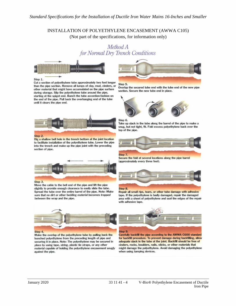
Standard Specifications for the Installation of Ductile Iron Water Mains 16-Inches and Smaller
January 2020 33 11 41 - 4 V-Bio® Polyethylene Encasement of Ductile Iron Pipe
INSTALLATION OF POLYETHYLENE ENCASEMENT (AWWA C105) (Not part of the specifications, for information only)

Standard Specifications for the Installation of Ductile Iron Water Mains 16-Inches and Smaller
January 2020 33 11 43 - 1 Removal of SFPUC-CDD / SFWD-Owned Valve Box and Cover
SECTION 33 11 43
REMOVAL OF SFPUC-CDD / SFWD-OWNED VALVE BOX AND COVER
PART 1 – GENERAL
1.01 WORK INCLUDED
A. Work under this Section includes saw cutting, excavating, removing and disposing of pavement, excavating the hole to the dimensions as specified by the City Representative, removing all existing SFPUC-CDD valve boxes and valve covers to be abandoned or as indicated by the City Representative.
B. This work also includes providing traffic control and routing; furnishing and placing sand backfill; restoring pavement, sidewalk, and other roadway structures that have been removed during the progress of the work, unless otherwise specified herein and clean the site of the work together with other work necessary or incidental thereto.
C. The Contractor shall dispose of the boxes as the Contractor’s property and return all box covers to the SFPUC-CDD Corporation Yard at 1990 Newcomb Avenue, or at the location indicated by the City Representative.
1.02 RELATED SECTIONS
A. The latest version of SFDPW Standard Specifications
B. Section 31 23 36 – Excavation and Backfill
C. Section 32 10 00 – Pavement Restoration
PART 2 – PRODUCTS
A. Not Used.
PART 3 – EXECUTION
3.01 REMOVAL OF VALVE BOX AND COVER
A. The Contractor shall notify the City Representative in writing 7 calendar days prior to scheduling the removal of abandoned valve boxes and valve covers. The City Representative shall identify the abandoned valve boxes and covers that are to be removed by marking them on the field. This removal work shall be completed before the final pavement restoration, as applicable.

Standard Specifications for the Installation of Ductile Iron Water Mains 16-Inches and Smaller
January 2020 33 11 43 - 2 Removal of SFPUC-CDD / SFWD-Owned Valve Box and Cover
B. The Contractor shall saw cut 2’ x 2’ square minimum the pavement around the valve cover and remove the valve box at least 18 inches below the roadway surface. The removal of the plate under the valve box is optional.
C. The hole shall be backfilled in accordance with the provisions of Section 31 23 36 - Excavation and Backfill.
D. The concrete base and pavement removed shall be restored to match the existing in accordance with the provisions of Section 32 10 00 - Pavement Restoration.
END OF SECTION

Standard Specifications for the Installation of Ductile Iron Water Mains 16-Inches and Smaller
January 2020
33 12 13 - 1 Installation of Screw Taps, Service Pipe and Fittings
SECTION 33 12 13
INSTALLATION OF SCREW TAPS, SADDLES, SERVICE PIPE AND FITTINGS
PART 1 – GENERAL
1.01 WORK INCLUDED
A. Work under this Section includes the removal of pavement; excavation of service trench and sidewalk as necessary for SFPUC CDD to make connections with service meters or existing service pipe; drilling, tapping and installing screw taps; and trenchless installation of 1-inch service pipe, where necessary.
1.02 RELATED SECTIONS
A. Section 31 23 36 - Excavation and Backfill
B. Section 33 10 00 – Water Utility Piping materials
C. Section 33 11 00 – Installation of 16-Inch and Smaller Water Mains and Appurtenances
D. Section 33 11 41 – V-Bio® Polyethylene Encasement of Ductile Iron Pipe
1.03 REFERENCES
A. SFPUC-CDD Standard Plans CDD-LP-201 through CDD-LP-216
PART 2 – PRODUCTS
2.01 MATERIALS
A. Service Fittings
1. Service fittings shall be made of bronze or brass, in conformance with AWWA C-800.
B. Service Pipes
1. The allowable diameters for service pipes are 1, 2, 4, 6, 8, 12 inches. Service pipes 2-inch and smaller shall be copper tubing type K, soft or hard. Service pipe larger than two inches shall be ductile iron pipe.

Standard Specifications for the Installation of Ductile Iron Water Mains 16-Inches and Smaller
January 2020
33 12 13 - 2 Installation of Screw Taps, Service Pipe and Fittings
PART 3 – EXECUTION
3.01 INSTALLATION OF SERVICE PIPES AND METER
A. SFPUC-CDD shall install service pipe connections to existing mains at cost to the project sponsor. If directed by SFPUC-CDD, the Contractor may install service pipe connections to new but not active water mains. The service pipe, valves, and fittings shall be installed from the new main to a point inside the meter box. SFPUC-CDD personnel will furnish and install the water meter at cost to the project sponsor.
B. Meter boxes, meter vaults and covers shall be installed by the SFPUC-CDD at cost to the project sponsor or if directed by SFPUC-CDD, installed by the Contractor. Pipes installed by the Contractor upstream of the meter shall be pressure tested before the installation of the meter by SFPUC-CDD. Meters and meter boxes shall be installed on the sidewalk per SFPUC “Rules and Regulations Governing Water Service to Customers,” Section A, Rule 2.
C. Each type of service (irrigation, domestic, fire) shall have a separate line and a meter.
D. The location of the service meter, except for fire services, shall be at the principal frontage of the premises, in area between the curb line and the customer’s premises. The Contractor shall not locate the meter in the traveled way of City streets, private roads or driveways, and curb ramps.
E. For fire services, a 5/8” meter shall be installed on the bypass of the backflow preventer by SFPUC-CDD personnel.
F. All backflow preventers shall be installed inside private properties, not more than twenty five (25) feet from the back of the domestic, irrigation, or reclaimed water meter or not more than twenty (25) feet of the back of the curb for fire services.
3.02 INSTALLATION OF SCREW TAPS AND SERVICE SADDLES
A. Drill, tap and install screw taps as shown on the drawings or as required by the City Representative. Any screw tap not satisfactorily installed in the opinion of the City Representative shall be removed and replaced at the expense of the Contractor. Where the screw tap installation is unsatisfactory, it shall be removed and replaced with a solid cast iron plug at no cost to the City. The City Representative shall determine the location of the relocated screw taps.
B. The Contractor shall not leave any “coin” cut out from the main for the installation of screw taps. The Contractor shall provide all “coin for 2” screw taps to the City Representative. It is the Contractor’s responsibility to remove any object left inside the newly installed pipe.
Standard Specifications for the Installation of Ductile Iron Water Mains 16-Inches and Smaller
January 2020
33 12 13 - 3 Installation of Screw Taps, Service Pipe and Fittings
C. Install brass saddles for 2 inch services on mains 8-inch or smaller per the manufacturer’s recommendations and per Standard Plans CDD-LP-201B and CDD-LP-202B.
3.03 SERVICE TRENCH EXCAVATION AND BACKFILL
A. Service trench excavation and backfill shall be in accordance with Section 31 23 36 - Excavation and Backfill.
B. The service trench shall be of sufficient width to properly install the service pipe and have a flat bottom two feet below the final gutter grade. The gutter grade shall be defined as the existing gutter grade or six inches below the official grade (grade at top of curb as established by the San Francisco Board of Supervisors) whichever is lower.
C. The bottom of the trench shall slope uniformly to the main from a point approximately ten feet from the main.
D. Service trench pavement restoration shall be performed in accordance with the provisions of Section 32 10 00 - Pavement Restoration of the Specifications
3.04 SERVICE FITTINGS
A. Contractor shall make cold flares by use of flaring tools approved by the Water Department whenever a flare type fitting is furnished. Heat shall not be applied to flare tubing. Joints for other type of fittings shall be in accordance with the method recommended by the manufacturer and approved by the Water Department.
3.05 INSTALLING SERVICE PIPE AND FITTINGS
A. The Contractor shall use trenchless methods to install 1-inch service pipe across existing traffic lanes wherever possible. Approval of the City Representative shall be obtained before any open cut excavation for 1-inch service line is permitted in the existing traffic lanes. The service meter will be installed and connected to the service line by the Water Department.
1. When instructed by the City Representative. The Contractor shall renew 1-inch long plastic service pipes (when service pipes are connected to the main on the opposite side of the street) by disconnecting the plastic pipe from the water main and the service meter (at the 1-inch plastic adapters) and pulling the new 1-inch copper through the 1-inch plastic service pipes at the same location instead of trench excavation. These renewals shall be scheduled and coordinated with the City Representative in advance of installation so as to minimize water service disruption to existing customers.
Standard Specifications for the Installation of Ductile Iron Water Mains 16-Inches and Smaller
January 2020
33 12 13 - 4 Installation of Screw Taps, Service Pipe and Fittings
B. For two inch and larger service pipe installations or where trenchless methods for 1-inch services are not possible, the Contractor shall dig trench under the curb, gutter, sidewalk and parking strip (where present) to the meter box as shown in CDD Standard Plans.
C. When the installation of the pipe through the basement wall is part of the service change over and is done by SFPUC-CDD personnel, SFPUC-CDD personnel will temporarily plug the annular gap between the pipe and the wall opening if they complete the work within 3 hours of the end of the Contractor’s work shift. The City Representative will inform the contractor of the temporary plug as soon as possible so that the Contractor can replace with a permanent plug. Contractor shall plug the gap if SFPUC-CDD personnel complete the plumbing work earlier than 3 hours of the end of the Contractor’s work shift. The Contractor is responsible for all leaks resulting from his/her work.
D. All service trench pavement restoration shall be performed in accordance with the provisions of Specifications Section 32 10 00 - Pavement Restoration of these Specifications.
E. All installation of 2-inch service pipe and installation of 1-inch service pipe in open trench excavations will be performed by SFPUC-CDD.
END OF SECTION

Standard Specifications for the Installation of Ductile Iron Water Mains 16-Inches and Smaller
January 2020 33 13 00 - 1 Sanitary Work Practices and Disinfection Of Water Utility Distribution
SECTION 33 13 00
SANITARY WORK PRACTICES AND DISINFECTION OF WATER UTILITY DISTRIBUTION
PART 1 – GENERAL 1.01 SUMMARY
A. This Specification Section: summarizes requirements sanitary construction practices that Contractor must follow to minimize potential contamination of the drinking water system. Details are also included for cleaning, draining, dechlorination, disinfection and testing of drinking water components and facilities associated with the construction of these facilities or impacts to existing facilities as a result of construction.
1.02 SCOPE OF WORK
A. All construction tasks to add or modify drinking water facilities must be implemented using sanitary protocols to prevent or remove contaminants prior to facility startup. Contaminants include, but are not limited to, fuels, hazardous materials, chemicals and solvents, radioactive materials, construction materials and debris, dirt, microorganisms, surface water runoff, groundwater, rodents, vectors, birds and other animals that may degrade drinking water quality.
B. The Contractor shall be responsible for sanitary work practices and the cleanup of
all drinking water components and facilities affected by the work, before they are put into operation.
C. The Contractor shall post a sign that would be visible for everyone who are within
the work perimeter to implement the Sanitary Practice Protocol.
D. The Contractor shall be responsible for draining and dechlorination of any water following initial limited gravity draining performed by the City. Water may be a result of leaks, intrusion and other sources from components and facilities affected by the work. The Contractor shall be responsible for compliance with all regulations related to the discharge of water, including obtaining and adhering to all necessary permits and keeping all correspondence and records available to the City Representative.
E. Unless otherwise specified, City will perform initial gravity draining, soak testing,
disinfection, dechlorination, flushing, sample collection and water quality testing of all pipelines 24 inches in diameter and smaller and water storage facilities affected by the work. The City Representative will contact regulatory agencies for discharges related to initial draining, flushing and disinfection.
Standard Specifications for the Installation of Ductile Iron Water Mains 16-Inches and Smaller
January 2020 33 13 00 - 2 Sanitary Work Practices and Disinfection Of Water Utility Distribution
1.03 REFERENCES
The Contractor shall use the latest edition of the following references: A. American National Standard Institute (ANSI) / National Sanitation Foundation
International (NSF) Standard 60 and 61 for Drinking Water System. B. American Water Works Association (AWWA) Standards:
1. C651 (Disinfecting Water Mains) 2. C652 (Disinfection of Water-Storage Facilities) 3. C653 (Disinfection of Water Treatment Plants) 4. C654 (Disinfection of Wells)
C. Title 22 of California Code of Regulations (Title 22), including California
Waterworks Standards (Division 4, Chapter 16).
D. Standard Methods for the Examination of Water and Wastewater, 20th Edition, as published by the American Public Health Association.
E. Other standards as directed by City Representative.
1.04 SUBMITTALS
A. Not less than 60 days prior to the commencement of work on any facilities, the Contractor shall submit to the City Representative proof of ANSI/NSF Standard 61 certification for materials, lubricants and products that will result in its contact with the drinking water per Article 2.3 and meet “Indirect Additives” requirements under Article 7 of Title 22 California Waterworks Standards. Testing and certification is required to be from one of the ANSI accredited organizations. The indirect additives must be used within their specific ANSI/NSF61 certification requirements.
B. Not less than 60 days prior to the commencement of work on any facilities, the
Contractor shall submit to the City Representative a “Sanitary Work Practices Plan” describing the procedures for work involving components, equipment, tools, structures and work areas with the potential for direct contact with drinking water. The Sanitary Work Practices Plan shall describe the Contractor’s plan to minimize contamination of the components and facilities during transportation, storage and construction. The Sanitary Work Practices Plan shall address the following requirements:
1. Minimizing physical contamination of the internal surfaces of the existing
and newly installed drinking water system components.

Standard Specifications for the Installation of Ductile Iron Water Mains 16-Inches and Smaller
January 2020 33 13 00 - 3 Sanitary Work Practices and Disinfection Of Water Utility Distribution
2. Preventing chemical and biological contamination (e.g. oil, grease,
residual lubricants, dirt, cross contamination, wastewater, etc.).
3. Preventing the introduction and loss of foreign materials (construction debris, dirt, garbage, construction material, tools, etc.) into the drinking water system.
4. Preventing the ingress of vandals or wildlife (birds, rodents, animals,
insects etc.) into the drinking water system.
5. Preventing the intrusion of non-drinking water into the pipelines, tanks and appurtenances. Non-drinking water sources include, but are not limited to, surface water runoff, rain water, contaminated drinking water, groundwater, etc.
6. Post-construction cleanup that may include localized spray or swab
disinfection of the components and facilities upon completion of work.
7. Cleanup and disinfection of the components as a preventive measure as directed by the City Representative. If disinfection of the facility is to be performed by the Contractor, the Contractor’s plan shall include:
(a) Disinfectant name and concentration (b) Proposed disinfection method. (c) A diagram showing all pipes including the length, valves and
appurtenances to be disinfected, as well as the sampling, monitoring and chemical injection locations.
(d) Flushing velocity and flow calculations. (e) Calculations for disinfectant quantity to be used. (f) Sampling Plan (g) Material Safety Data Sheets (MSDS) for the disinfectant to be
used. 8. Description of sanitary controls established by the Contractor in
accordance with AWWA Standards. C. Not less than 60 days prior to the commencement of dechlorination, the
Contractor shall submit to the City Representative a “Draining, Dechlorination and Monitoring Plan” for compliance with regulatory requirements.
1. The Plan shall include information on personnel, equipment, instruments,
chemicals, sampling locations, and procedures related to the calibration of instruments, monitoring, notification and recordkeeping.
2. The Contractor shall also provide the City Representative with an estimate
Standard Specifications for the Installation of Ductile Iron Water Mains 16-Inches and Smaller
January 2020 33 13 00 - 4 Sanitary Work Practices and Disinfection Of Water Utility Distribution
of the water volume and time period for the discharge.
3. Refer to Article 3.2 for draining and dechlorination.
E. The Contractor shall show timelines on the project schedule for all cleaning,
draining, dechlorination and disinfection activities. F. Dechlorination monitoring records as described in Article 3.2, or as directed by
the City Representative. G. If disinfection is required to be performed by the Contractor, the Contractor shall
submit disinfection monitoring records including location, chemical name, concentration, dosage, contact time, and other records as directed by the City Representative.
H. Communications, permits, and records with Regulatory Agencies.
PART 2 – PRODUCTS 2.01 COMPONENTS
A. All chemicals, materials, and/or products that are used in construction/ installation and that will be in contact with drinking water are collectively described as drinking water system components (hereinafter the component or components). These include, but are not limited to, process media, protective coating and lining materials, sealants, lubricants and adhesive compounds.
2.02 FACILITIES
A. All equipment, pipelines, valves, fittings, pumps, wells, mechanical devices, and storage tanks that are used for treatment, conveyance, and/or storage of drinking water are collectively described as drinking water system facilities (hereinafter the facility or facilities).
2.03 INDIRECT ADDITIVES
A. All components and facilities that are supplied by the Contractor such as materials, lubricants, and products (e.g. valves, pumps, fittings) in the production, treatment or distribution of drinking water that will result in its contact with the drinking water are required to be certified as meeting the specifications of ANSI/NSF61 and meet California Waterworks Standards. It includes, but is not limited to, process media (carbon, sand), protective materials (coatings, linings, liners), joining and sealing materials (solvent cements, welding materials, gaskets, lubricating oils), pipes and related products (pipes, tanks, fittings), and

Standard Specifications for the Installation of Ductile Iron Water Mains 16-Inches and Smaller
January 2020 33 13 00 - 5 Sanitary Work Practices and Disinfection Of Water Utility Distribution
mechanical devices used in treatment/ transmission/ distribution systems (pumps, valves, chlorinators, separation membranes).
There are three ways to comply with the California Waterworks Standards for Indirect Additives. They are listed below in the preferred order:
1. All Components: The entire material, lubricant, or product is certified as meeting the specifications of ANSI/NSF61. The Contractor shall submit proof of ANSI/NSF61 certification for the entire material, lubricant, or product to the City Representative for acceptance.
2. All Wetted Components: If the entire material, lubricant, or product is NOT certified as meeting the specifications of ANSI/NSF61, then all wetted components that may result in its contact with drinking water are required to be ANSI/NSF61 certified. The Contractor shall submit a list of all wetted components, manufacturers of the components, materials of construction, and proof of ANSI/NSF61 certification for the components to the City Representative for review and acceptance. The contractor shall collect data for each wetted component and associated certification in a timely manner taking into account that information gathering for each component may be a time consuming process.
3. Some or No Components/Waiver: If ANSI/NSF61 certified materials cannot be used or if there are no certified alternatives, then the Contractor shall submit justification with supporting information that demonstrates equivalent public health protection for use of the proposed product to the City Representative for review and waiver by SFPUC and California Department of Public Health (CDPH). In order to demonstrate the same level of public health protection, CDPH may require leach tests or other criteria on a case-by-case basis for the material or product, which can be a complex and time consuming process that should be accounted for by the Contractor. CDPH will need 30 days to review justification package; however, CDPH regulatory review timelines can be unpredictable at the time of submittal and there are risks that CDPH may deny the approval request.
B. “All Components” compliance method for the entire material, lubricant, or product (valves, pumps etc.) provides clear regulatory compliance and is the best option as it eliminates chances of delay (some of which may be classified as Avoidable Delay) associated with further reviews and CDPH approval.
C. The Contractor shall comply with ANSI/NSF61 regulatory requirements as
specified in Articles 1.3 and 2.3, obtain complete ANSI/NSF61 certification documentation, and provide timely submittals to the City Representative for acceptance not less than 60 days prior to the commencement of work on any facilities to avoid any schedule delays. If ANSI/NSF61 certified materials are

Standard Specifications for the Installation of Ductile Iron Water Mains 16-Inches and Smaller
January 2020 33 13 00 - 6 Sanitary Work Practices and Disinfection Of Water Utility Distribution
available, but the Contractor fails to procure and install ANSI/NSF61 certified materials, or fails to provide complete NSF61 certification documentation, then the Contractor shall be responsible for schedule delays and related overhead expenses associated with corrective actions and with any necessary regulatory approvals. Such schedule delays will be classified as Avoidable Delays under the Contract Documents.
D. If ANSI/NSF61 certified materials are not feasible or if certified materials do not
exist, then the contractor shall provide timely submittals with workable alternative solutions to the City Representative for review and acceptance not less than 60 days prior to the commencement of work on any facilities to avoid any schedule delays. This will also require review and approval by CDPH as specified in Article 2.3 (A) (3). The Contractor shall implement mitigation measures and meet regulatory requirements as directed by the City Representative. The Contractor shall be responsible for the cost of any extended overhead as a result of non-compensable schedule extension. In no event will delays associated with review and approval by CDPH entitle Contractor to a compensable time extension.
PART 3 – EXECUTION 3.01 SANITARY WORK PRACTICES
A. The Contractor shall exercise due care and implement sanitary work practices as described hereunder to prevent physical, chemical, biological and animal contamination of all components and facilities.
B. The Contractor shall establish sanitary controls in accordance with AWWA
Standards C651 (most recent edition) Section on “PREVENTIVE AND CORRECTIVE MEASURES DURING CONSTRUCTION.”
C. The Contractor shall be responsible for implementation of its Sanitary Work
Practices Plan at all times. D. All materials stored on site shall be kept in a clean and undamaged condition.
Hazardous materials shall be stored at least 25 feet away, or as directed by the City Representative, from all drinking water facilities (in service or out of service), on grounds where surface drainage slopes away from drinking water facilities and away from areas of standing water. All temporary human waste collection systems (i.e. “Portapotties”, or holding tanks) shall be kept a minimum of 25 feet away, or as directed by the City Representative, from any drinking water storage or conveyance system, and will be placed in a manner that will prevent any leakage from contaminating any part of the components/facilities storage or conveyance system.
Pipelines, valves and other appurtenances shall be kept capped, wrapped or

Standard Specifications for the Installation of Ductile Iron Water Mains 16-Inches and Smaller
January 2020 33 13 00 - 7 Sanitary Work Practices and Disinfection Of Water Utility Distribution
housed to prevent unsanitary conditions, rust, animal nesting and other contamination hazards. Plugs of rags, wood, cotton, or similar materials are not acceptable.
E. Prior to installation of any facilities and/or components, all plugs, caps, dirt,
debris, grease, and foreign material shall be removed. If dirt, garbage, animals or other sanitary hazard has entered a pipeline, if the pipeline has become engulfed with standing water or rainwater, or disinfection of the components (e.g. valves, small pipe sections, taps etc.) is otherwise required prior to installation, the Contractor shall spray or swab the interior surface using a nominal 1% sodium hypochlorite solution as the disinfectant as directed by the City Representative. The solution should have at least 10,000 milligrams per liter (mg/L) chlorine concentration. For the purpose of preventing corrosion by the disinfectant, and upon request by the City Representative, the Contractor may need to rinse the interior surface with drinking water to remove the disinfectant after the disinfectant has been in contact with the surface for at least five (5) minutes.
F. Once cleaned, all components and facilities shall be stored under controlled
conditions to prevent re-contamination. If the City Representative finds unacceptable care or cleanliness of the components and facilities prior to installation or being put into service, the Contractor will be required to clean the components and facilities to the satisfaction of the City Representative. The Contractor shall be solely responsible for the cost of the required cleaning.
G. If the Contractor is required to enter the interior of any in-service facility, all
tools, equipment and boots shall be washed and cleaned to remove dirt, and disinfected with a nominal 200 mg/L sodium hypochlorite solution prior to entering the facility, or as directed by the City Representative. Material and tools may be rinsed with drinking water to remove residual disinfectant after 15 minutes of contact time, or as directed by the City Representative.
H. The Contractor shall remove all dirt, dust, oil and foreign materials from all
components and facilities after their installation and prior to the disinfection to the satisfaction of the City Representative.
I. The Contractor shall be responsible to take all safety and precautionary measures,
including safe handling of chemicals, safe operation of equipment/tools, and the use of appropriate personal protective equipment during and at the end of construction. The Contractor shall provide the City Representative with Material Safety Datasheets (MSDS) of all chemicals and other hazardous materials used by the Contractor at the site. The MSDS of all chemicals shall be kept on-site at all times for City Representative review.
J. The Contractor shall notify the City Representative immediately of any suspected
vandalism, sewage leak, contaminated soils, chemical spill or construction activity that could cause contamination or otherwise compromise the integrity of

Standard Specifications for the Installation of Ductile Iron Water Mains 16-Inches and Smaller
January 2020 33 13 00 - 8 Sanitary Work Practices and Disinfection Of Water Utility Distribution
the facilities.
3.02 DRAINING AND DECHLORINATION OF PIPELINES AND STORAGE
FACILITIES A. Prior to construction, City personnel will perform initial gravity draining of the
pipelines and storage facilities to the extent possible without pumping. The Contractor shall be responsible for draining and/or pumping water that remains in the facility as a result of leaks, intrusion, or other sources, to pursue the contract work. The Contractor shall dechlorinate any water drained or pumped from the components or facilities prior to discharging to surface water or storm drainage according to his submittal and as directed by the City Representative.
B. The City drinking water typically contains detectable total chlorine residual up to
4 mg/L and has an elevated pH up to 9.5. The discharge of water to a surface stream or creek may also cause turbidity in the receiving water to increase. Prior to discharging water, the Contractor shall be responsible for dechlorinating all water that is drained/pumped out of the facility. The Contractor shall treat, monitor and record all water discharges into storm drains, surface streams, or other locations not connected to a sanitary sewer to ensure compliance with all applicable City, Regional Water Quality Control Board (RWQCB) and local regulatory requirements. In addition, the City Representative may require the Contractor to monitor these parameters at a different frequency during unusual water quality conditions.
The RWQCB requirements are as follows:
1. The discharged water shall have non-detectable chlorine residual (<0.05
mg/L). The frequency of monitoring in the effluent shall be every 60 minutes for the duration of the discharge.
2. The pH of the discharged water shall be in the range of 6.5 to 8.5. If the
discharge fails to meet this limitation additional samples may be collected in the receiving water stream to verify compliance with the pH standard. If the pH standard cannot be met in the receiving water then sampling should be conducted 50 feet upstream and downstream of the discharge to determine if the ambient pH has not been changed by more than 0.5 pH unit. If the standard still cannot be attained then further treatment prior to discharge is necessary. The frequency of monitoring in the effluent shall be every 60 minutes for the duration of the discharge.
3. To limit erosion when discharging to the receiving water a perforated pipe
will be attached to the discharge line in the shape of a T (See SFPUC WS&TD SOP).
Standard Specifications for the Installation of Ductile Iron Water Mains 16-Inches and Smaller
January 2020 33 13 00 - 9 Sanitary Work Practices and Disinfection Of Water Utility Distribution
4. The discharge shall not cause pollution, contamination, or nuisance. The
discharge shall cause no scouring or erosion at the point where discharged water enters the receiving water.
C. At no cost to the City, the Contractor shall provide all necessary equipment (for
example tanks, pumps, valves, instruments, controls, chemicals) and qualified on-site personnel for managing and monitoring the water discharges. The Contractor shall notify the City Representative for inspection of the equipment set up prior to the commencement of draining and dechlorination.
D. Total Chlorine residual must be monitored using EPA approved test methods,
which can be found in the latest edition of Standard Methods for the Examination of Water and Wastewater or at the EPA website. The City typically uses Hach Pocket Colorimeter (DPD Method) for total chlorine residual monitoring during dechlorination. The test kit is available from Hach (www.hach.com). Note that total chlorine and free chlorine are measured using different test kits.
E. The Contractor shall, at no cost to the City, provide, configure and set up an
appropriate dechlorination system using either a drip feed, or a metering pump feed of a nominal 25% sodium bisulfite solution, or other suitable chemicals approved by the City Representative.
F. The Contractor shall, at no cost to the City, maintain pH levels while complying
with other parameters specified in Article 3.2.B, by adjusting the flow rate of dechlorination chemical, or by using acid and/or alkali. Note that sodium bisulfite has some pH depression capability.
G. The Contractor shall be responsible for all regulatory issues related to this
discharge including obtaining, paying for, adhering to all permit terms and conditions and for keeping written records of any regulatory communication available for the City Representative. In the event of an accidental release of water discharges not meeting the RWQCB requirements specified in Article 3.2, the Contractor shall immediately notify the City Representative and take necessary actions to stop the discharge and correct the process to meet the discharge requirements. The Contractor shall provide relevant monitoring data and an estimate of the volume of water discharged that did not meet regulatory requirements.
H. During all periods of discharge, the Contractor shall monitor and maintain records
for verification that the water has been dechlorinated and pH adjusted to meet the RWQCB requirements specified in Article 3.2. The Contractor shall prepare and maintain a daily log of the monitoring and sampling results, in addition to completing the Discharge Monitoring Form (DMF) provided in this Section as Appendix ‘A’ and provide records of both the daily log and the DMF to the City Representative. The Contractor shall monitor and record all such discharges at a

Standard Specifications for the Installation of Ductile Iron Water Mains 16-Inches and Smaller
January 2020 33 13 00 - 10 Sanitary Work Practices and Disinfection Of Water Utility Distribution
frequency of not less than once per hour. The daily log, recorded in ink, shall include, but are not limited to: dates, time, sampler names, signatures, sample locations, discharge locations (including latitude and longitude), instrument and equipment calibration records, estimated discharge flow rates, chemical feed rates, total chlorine residuals and pH at upstream and downstream of the dechlorination points, turbidity and other parameters in accordance with Article 3.2. The Contractor shall also calculate the total volume of water discharged and total quantity of chemicals used on a daily basis.
I. The Contractor shall provide the original copies of the previous day’s monitoring
logs to the City Representative by 10:00 AM the following calendar day. J. Where the Contractor plans to use a sanitary sewer for the discharge, the
Contractor shall submit the request to the City Representative for prior review and acceptance prior to initiating the discharge. The Contractor shall provide detailed information regarding the sewer location, approved backflow devices, anticipated dates of the discharge, and approximate flow rates and volumes. If permission to use the sewer is granted by the City Representative, the Contractor shall comply with all local agency requirements, including schedule submittals, notifications, flow rate limits, applicable water quality standards, monitoring and pre-treatment requirements. The Contractor shall be responsible for all sewer related permitting and discharge issues and costs.
3.03 DISINFECTION OF CONVEYANCE FACILITIES (PIPELINES AND
ASSOCIATED APPURTENANCES) A. After installation of conveyance facilities and field tests by the Contractor, the
City may perform a soak test if new coatings, linings, sealants, or other chemicals may have been introduced or used by the Contractor as part of the work or if during the course of the project, contaminants are suspected of being introduced into the drinking water facilities. This soak test is for water quality testing that the Contractor’s work must pass prior to disinfection. City personnel may also perform a localized preliminary disinfection inside the conveyance facilities prior to soak tests and full scale disinfection. The Contractor may also be required to perform a localized preliminary disinfection, if necessary, as instructed by the City Representative.
B. In performing disinfection of a valve, City personnel may need access to both
sides of the valve. The Contractor shall be responsible for keeping the valve open and the pipeline dry during the preliminary disinfection. This preliminary disinfection process is estimated to take about four (4) hours at each location. The City Representative will notify the Contractor at the completion of the preliminary disinfection process.
C. Prior to putting these facilities into service, the City will perform a full-scale
disinfection of the conveyance facilities in accordance with the AWWA Standards

Standard Specifications for the Installation of Ductile Iron Water Mains 16-Inches and Smaller
January 2020 33 13 00 - 11 Sanitary Work Practices and Disinfection Of Water Utility Distribution
and the City’s internal disinfection procedures. D. The Contractor shall notify the City Representative not less than 5 weeks prior to
a facility being ready for disinfection. The Contractor shall coordinate construction activities to facilitate the disinfection conducted by City personnel. The Contractor shall provide access, support and equipment, as needed, to assist City personnel in completing the disinfection.
E. The Contractor shall plan the work schedule by taking into consideration the time
required by City personnel for disinfection, which typically includes filling, disinfecting, flushing, dechlorinating, and taking water samples from the disinfected facilities for bacteriological analysis and residuals management. Although the estimated time required for disinfecting each pipeline segment may be up to 5 business days, depending upon size and length of pipe, the actual time required for the completion of disinfection and bacteriological testing may vary depending on site conditions. It is the Contractor’s responsibility to plan ahead of construction schedule and coordinate with the City Representative to allow sufficient time for SFPUC personnel to complete the disinfection work.
F. After completion of disinfection, the City Representative will arrange for City
personnel to collect water samples for bacteriological analysis. The passing criteria for satisfactory disinfection of the components and facilities is that all water samples shall indicate the absence of total coliform bacteria. Any sample result that shows positive for total coliform is considered a failed test.
G. If the Contractor is required to perform the preliminary and final disinfection of
the conveyance facilities as part of the Contract work, the Contractor shall follow the same procedures as described in Articles 3.3 above for the disinfection work performed by City personnel.
H. The City Representative will be responsible for contacting the governing
regulatory agencies on all matters related to the disinfections and related environmental discharges.
3.05 WATER QUALITY TESTS AND REMEDIAL MEASURES
A. Water quality tests include soak tests and bacteriological tests. The Contractor
may be required to perform these tests if directed by the City Representative. In that event, the Contractor shall be responsible for all the materials and labor to conduct these tests.
B. The City is responsible for collecting appropriate water samples upon completion
of soak tests and bacteriological tests. Samples will be analyzed for the appropriate contaminants and bacteriological parameters by the City.

Standard Specifications for the Installation of Ductile Iron Water Mains 16-Inches and Smaller
January 2020 33 13 00 - 12 Sanitary Work Practices and Disinfection Of Water Utility Distribution
C. If any of the water quality tests fails, the Contractor shall, at no cost to the City,
take appropriate remedial measures, as determined by the City Representative, to ensure that the components and facilities pass the specified water quality tests. These remedial measures may include, but are not limited to, aeration utilizing a compressor with an oil separator, draining/cleaning/refilling the component and/or facility, re-application of coating or sealant, or any combination of these and other remedial measures as determined by the City Representative. It is presumed that any failure to pass the specified water quality tests is due to foreign constituents introduced into the facility by the Contractor and/or by improper application of coating/sealing materials.
D. Upon the Contractor’s completion of all required remedial measures, the City
Representative will reschedule disinfection of the facility, if necessary, and the specified water quality tests as described above.
E. Disinfection and water quality testing of the components and facilities shall be
repeated until all water samples pass the specified water quality tests. All costs and time associated with assuring that the facility passes the specified water quality tests are the sole responsibility of the Contractor.
F. Facilities shall not be placed into service unless the required water quality tests
pass to the satisfaction of the Water Quality Engineer. G. The City is not responsible for the Contractor’s loss as a result of any delays in
project completion due to the failure of the initial and repeat water quality tests.
END OF SECTION
(See Appendix ‘A’ on following page)

Standard Specifications for the Installation of Ductile Iron Water Mains 16-Inches and Smaller
January 2020 33 13 00 - 13 Sanitary Work Practices and Disinfection Of Water Utility Distribution
APPENDIX ‘A’
REGIONAL TRANSMISSION SYSTEM DISCHARGE MONITORING FORM
Water Supply and Treatment Division
PROJECT INFORMATION
Project Name: ___________________________________________________________________________
SFPUC City Representative:
__________________________________________________________________________ Project Contractor:
___________________________________________________________________________ DISCHARGE LOCATION DETAILS
City and Cross Street(s):
____________________________________________________________________________ Latitude and Longitude: ___________________________N
____________________________W Receiving Water Body:
____________________________________________________________________________
DISCHARGE MONITORING DATA (attach additional sheets as necessary)
Date
Time
(hr)
Discharge Flow Rate (gpm)
Raw Cl2 Residual (mg/L)
Treated Cl2 Residual (mg/L)
Dechlor Feed Rate (gph)
Dechlor Chemical
Used
Treated pH
(su)
Sampler Initials

Standard Specifications for the Installation of Ductile Iron Water Mains 16-Inches and Smaller
January 2020 33 13 00 - 14 Sanitary Work Practices and Disinfection Of Water Utility Distribution
EROSION CONTROL MEASURES USED (describe)