water pumps feras marish, b.eng. - toronto hydro · aspe joins iapmo and wqrf in revising...
TRANSCRIPT
Grundfos Energy OptimizationWater Pumps
Feras Marish, B.Eng.

What is a Booster Pump?
In Hi-Rise Buildings
Booster installed after the City Meter
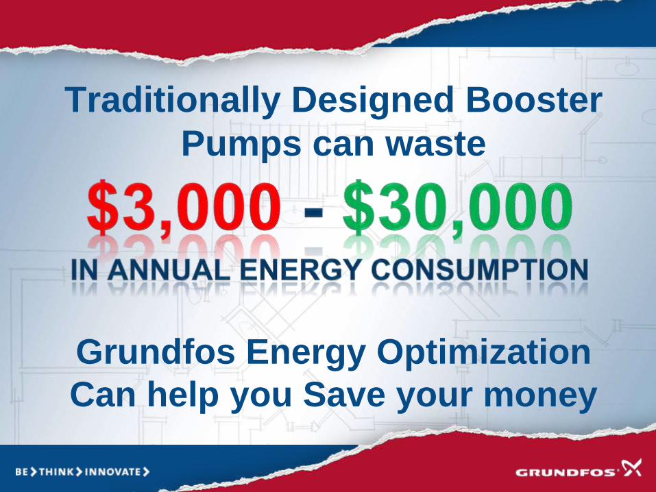
Traditionally Designed Booster
Pumps can waste
Grundfos Energy Optimization
Can help you Save your money

HOW DO WE DO IT?
Section 1
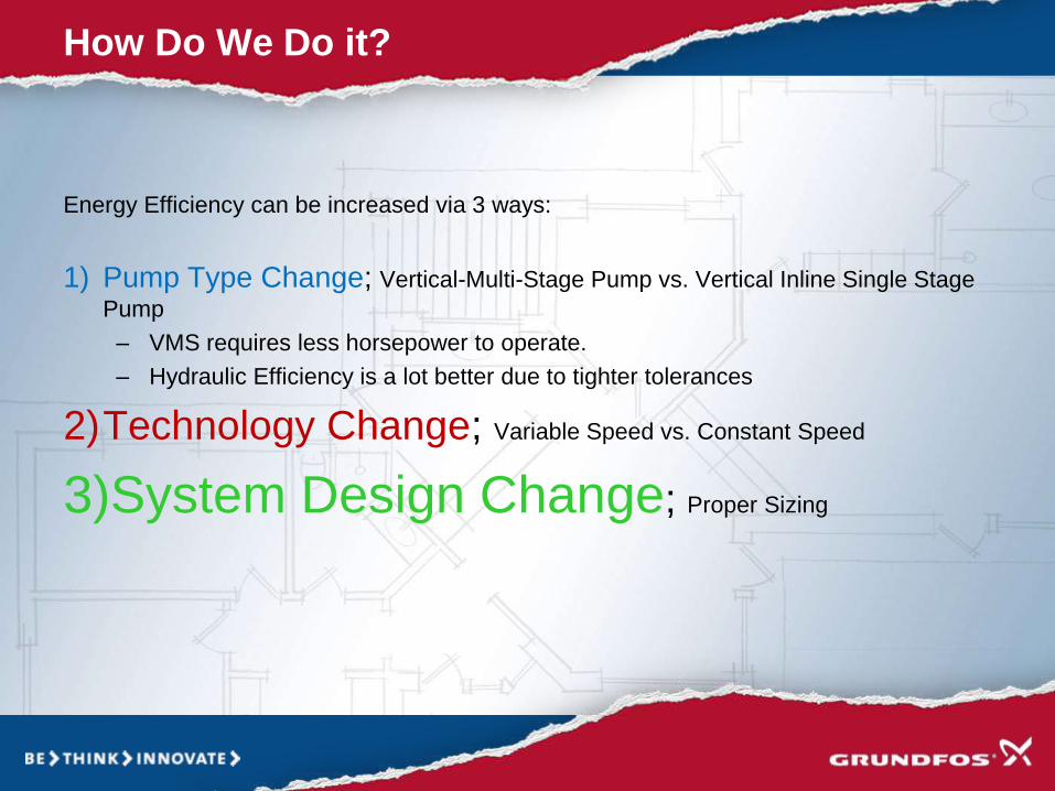
Energy Efficiency can be increased via 3 ways:
1) Pump Type Change; Vertical-Multi-Stage Pump vs. Vertical Inline Single Stage
Pump
– VMS requires less horsepower to operate.
– Hydraulic Efficiency is a lot better due to tighter tolerances
2)Technology Change; Variable Speed vs. Constant Speed
3)System Design Change; Proper Sizing
How Do We Do it?

Pump Type Change
Multi-Stage vs. Single-Stage

• Smaller Impeller requires
less Horsepower
• near-perfect geometries
and tolerances
• Internal leakage caused by
pressure differentials within
the pump minimized.
• An enhanced impeller
design reduces eddy flow
and friction losses.
• Laser Welded Stainless
Steel Impeller
Pump Type Change
Vertical Multi Stage Single Stage
• Large Impeller needed for
Pressure Boosting
Application, Larger HP.
• Hydraulic Inefficiencies
due to trimming of
impeller (Internal
Leakage)
• Cast Bronze Impeller;
cannot endure harsh
working conditions
(Cavitation and Erosion)

Pump Type Change
Vertical Multi StageSingle Stage

Design Change
Booster Sizing

• Hunters Curve
• Most hydronic heating systems and Domestic Cold Water (DCW) booster pumps are oversized. This oversizing occurs for several reasons such as;
o Lack of precise designing tools
o Compounding design safety factors
Designed for Maximum Flow
How are D.W. Boosters Sized?

• Characteristics
– Large variations in flow
– Constant Pressure
Actual Water Flow Demand in Multi storey buildings
Typical consumption profile, 24 hours

FLOW RATE SPREAD
88% of the flow
rates are under
50 gpm
The average
flow rate is
32 gpm

ASPE Joins IAPMO and WQRF in Revising Hunter's Curve
• “Such a large-scale statistical analysis of hourly use and flow patterns of
plumbing fixtures common in residential occupancies has never been done,”
Cole said. “The original Hunter model for public use was based
on assumptions only, not data. The Hunter model for private use was
based on morning calls in two hotels and one apartment. The scope of this
project greatly surpasses the original work piloted by Dr. Hunter. We are
excited about the potential results this project may bring forth for more
accurate water supply demand estimates, efficient pipe sizing, and precise
metering.”
• “ASPE is committed to supporting this critical research that will provide our
members with statistically sound information that will assist them in designing
plumbing systems that are even more efficient and cost effective,” stated Jim
Kendzel, ASPE Executive Director/CEO. “The plumbing industry needs to
continually invest in research to be able to provide the public with a safe and
efficient water supply and ASPE is proud to be working with IAPMO and WQRF
in supporting this project.”
DCW Booster are OVERSIZED
Submitted by [email protected] on Thu, 05/16/2013 - 13:21
http://aspe.org/node/1267

The Hydraulic Institute recommends operating between 70% and 120% of BEP
B.E.P – Best Efficiency Point
E
f
f
i
c
i
e
n
c
y
Flow
H
e
a
d
70% 120%
BEP
Over-sized
Pump run at
very low
efficiencies
0.1% (Pump Eff.
Measured in
some cases)

Technology Change
Variable Speed vs. Constant Speed

Common Constant Speed Booster
System

Pump running at Constant Speed
An example:
• A fixed speed water supply pump has a Hnom = 50 psi at Qnom
• Water Flow (Demand) is 98% of the time less than Max Flow
• To reduce flow, pressure will need to be increased to 90 psi
Required pressure = 50 psi
Q
H
Reduced
flow
Fixed
speed
Pressure at Fixed speed
pump solution = 90 psi
Excess
pressure
System
Nominal
flow Qnom
Constant speed pump system will result in:
• High energy consumption
• Noise
• Wear and stress on system (Pre-Mature Failure of mechanical components)
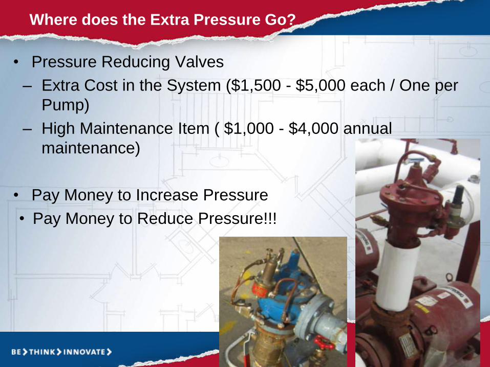
• Pressure Reducing Valves
– Extra Cost in the System ($1,500 - $5,000 each / One per
Pump)
– High Maintenance Item ( $1,000 - $4,000 annual
maintenance)
• Pay Money to Increase Pressure
• Pay Money to Reduce Pressure!!!
Where does the Extra Pressure Go?
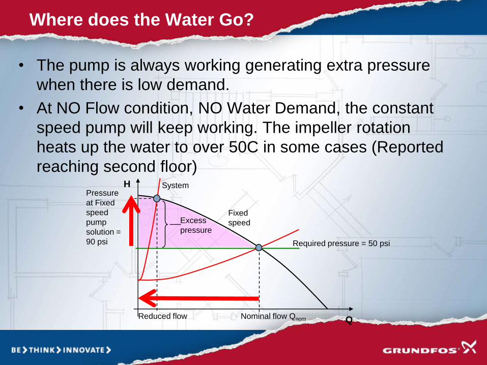
• The pump is always working generating extra pressure
when there is low demand.
• At NO Flow condition, NO Water Demand, the constant
speed pump will keep working. The impeller rotation
heats up the water to over 50C in some cases (Reported
reaching second floor)
Where does the Water Go?
Required pressure = 50 psi
Q
H
Reduced flow
Fixed
speed
Pressure
at Fixed
speed
pump
solution =
90 psi
Excess
pressure
System
Nominal flow Qnom

Life Cycle Cost (15 year Service Life)
Excerpt from: Optimizing Pump Systems: A Guide for Improved Energy Efficiency,
Reliability & Profitability, Pump Systems Matter and Hydraulic Institute
Percentages will vary based on
application
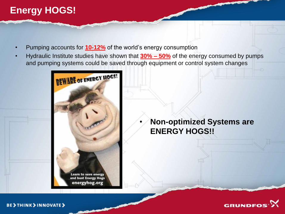
• Pumping accounts for 10-12% of the world’s energy consumption
• Hydraulic Institute studies have shown that 30% – 50% of the energy consumed by pumps
and pumping systems could be saved through equipment or control system changes
Energy HOGS!
• Non-optimized Systems are
ENERGY HOGS!!

Grundfos FULLY Variable Speed Booster System
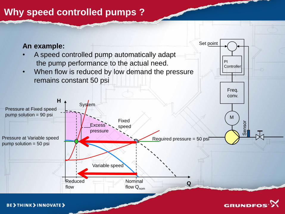
Why speed controlled pumps ?
An example:
• A speed controlled pump automatically adapt
the pump performance to the actual need.
• When flow is reduced by low demand the pressure
remains constant 50 psi
Variable speed
Freq.
conv.
M
PI
Controller
Set point
Required pressure = 50 psi
Q
H
Reduced
flow
Fixed
speed
Pressure at Fixed speed
pump solution = 90 psi
Excess
pressure
System
Nominal
flow Qnom
Pressure at Variable speed
pump solution = 50 psi

Does Operational change Help?
Manual Operational changes will not achieve the optimum energy savings for the
following possible reasons:
1. The Pumps are oversized by design
2. The pumps are at end-of-life condition (close to or over 15 years old) the
efficiency is very low (0.1 – 10 %)
3. The existing booster pump system is designed for constant speed operation
which is not suited for the Domestic Cold Water boosting-Variable Flow
application.
An Attempt
to save energy
via Manual
Sequence of
Operation
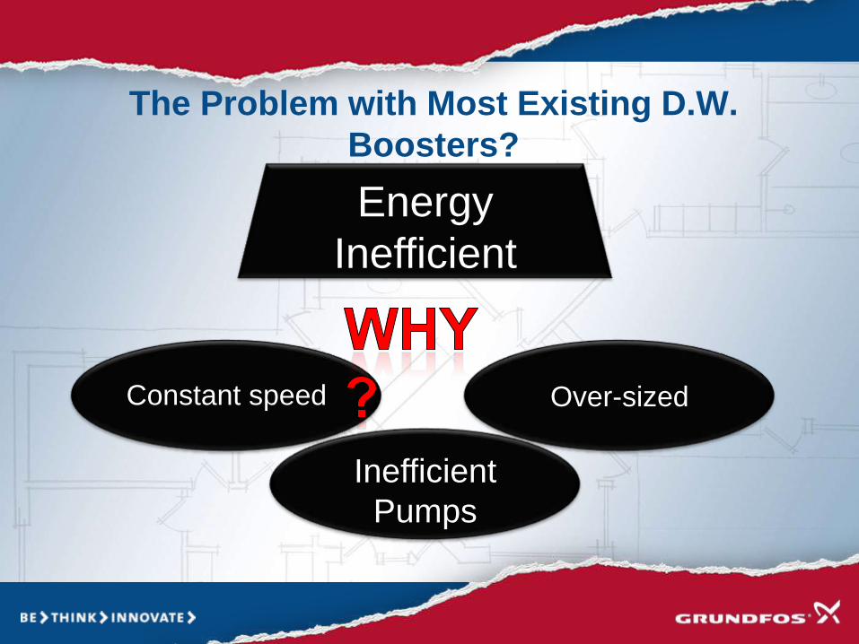
The Problem with Most Existing D.W.
Boosters?
Energy
Inefficient
Constant speed Over-sized
Inefficient
Pumps
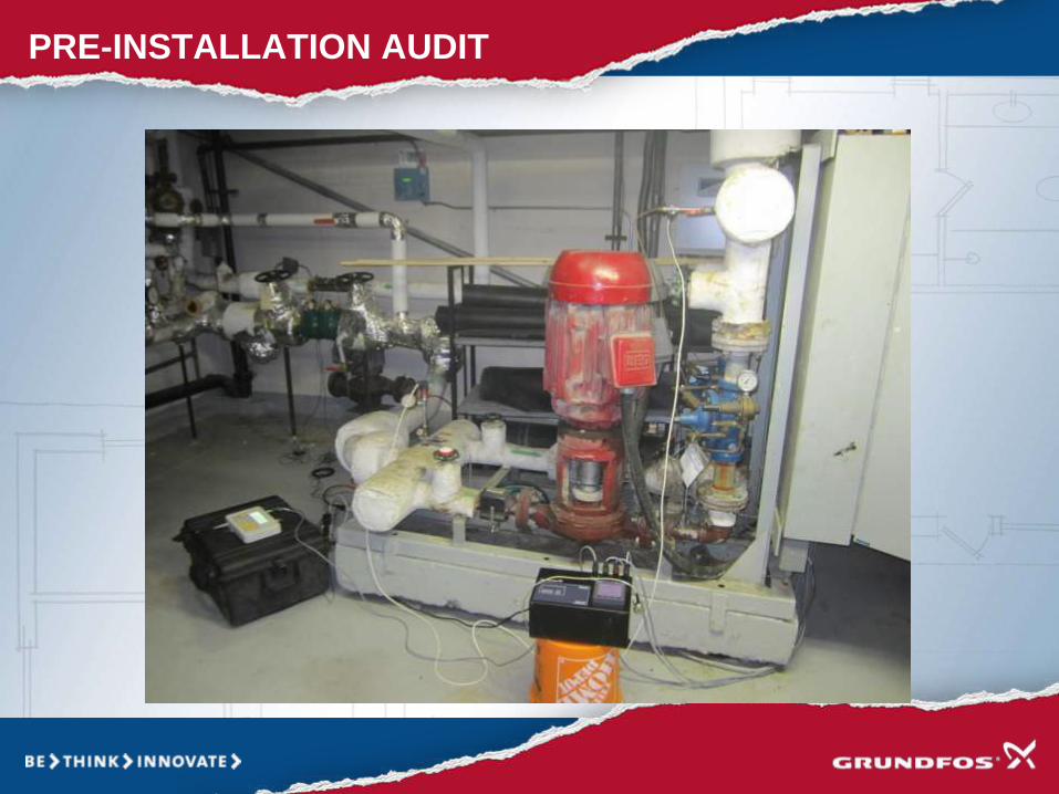
PRE-INSTALLATION AUDIT

POST INSTALLATION AUDIT

Grundfos Accuracy
Building
Existing System
Consumption
(kWh)
Esimated
Consumption
Savings (kWh)
Measured
Consumption
Savings
(kWh)
Consumption
Saving
Discrepancy
(%)
Building 1 198,759 157,357 152,972 2.79%
Building 2 198,567 165,495 171,393 3.56%
Building 3 369,404 342,113 332,814 2.72%
Building 4 237,196 197,867 198,574 0.36%
Building 5 166,112 133,364 131,106 1.69%
Building 6 312,480 268,386 266,282 0.78%
Building 7 154,861 122,490 118,053 3.62%
Building 8 332,277 298,669 291,133 2.52%
Building 9 151,880 137,960 140,108 1.56%
Building 10 142,707 119,297 119,944 0.54%
Building 11 158,795 136,269 132,719 2.61%
Building 12 142,329 140,439 137,527 2.07%
Building 13 175,256 164,548 164,843 0.18%
Building 14 127,932 125,689 124,669 0.81%
Building 15 167,740 165,420 161,031 2.65%
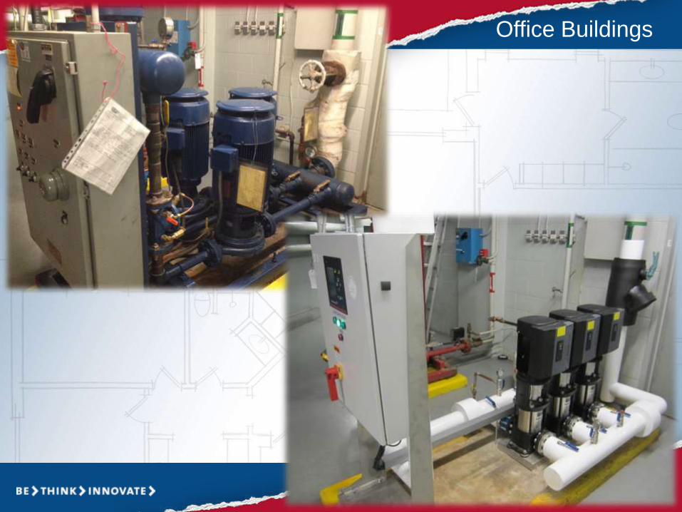
Office Buildings

More Energy
SavingsDomestic Hot Water Pump


Traditional 3-Piece Circulatior
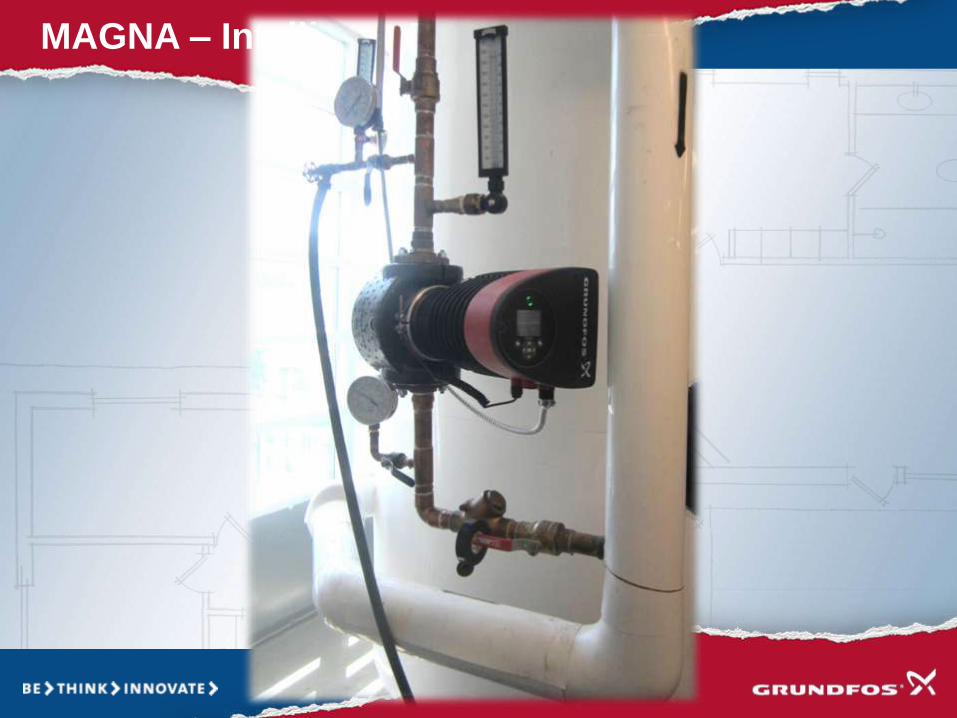
MAGNA – Intelligent Pump

MAGNA – Intelligent Pump

More Energy
SavingsHVAC Pumps


HVAC Pumps

Intelligent HVAC Pumps

Feras Marish, B.Eng.Business Development Manager – Energy
Optimization
Grundfos Canada
905-464-0490