waters sq detector · 2009-05-18 · v considerations specific to the sq detector solvent leakage...
TRANSCRIPT

Waters SQ DetectorQuick Start Guide
71500126603/Revision C
Copyright © Waters Corporation 2009All rights reserved

Copyright notice
© 2009 WATERS CORPORATION. PRINTED IN THE UNITED STATES OF AMERICA AND IRELAND. ALL RIGHTS RESERVED. THIS DOCUMENT OR PARTS THEREOF MAY NOT BE REPRODUCED IN ANY FORM WITHOUT THE WRITTEN PERMISSION OF THE PUBLISHER.
The information in this document is subject to change without notice and should not be construed as a commitment by Waters Corporation. Waters Corporation assumes no responsibility for any errors that may appear in this document. This document is believed to be complete and accurate at the time of publication. In no event shall Waters Corporation be liable for incidental or consequential damages in connection with, or arising from, its use.
Trademarks
ACQUITY UPLC, Connections Insight, ESCi, and Waters are registered trademarks of Waters Corporation. ACQUITY, Empower, IntelliStart, IonSABRE, MassLynx, T-Wave, UPLC, and ZSpray and “THE SCIENCE OF WHAT’S POSSIBLE.” are trademarks of Waters Corporation.
Nalgene is a registered trademark of Nalge Nunc International.
PEEK is a trademark of Victrex Corporation.
Other trademarks or registered trademarks are the sole property of their respective owners.
ii
Customer comments
Waters’ Technical Communications department invites you to tell us of any errors you encounter in this document or to suggest ideas for otherwise improving it. Please help us better understand what you expect from our documentation so that we can continuously improve its accuracy and usability.
We seriously consider every customer comment we receive. You can reach us at [email protected].
iii

Contacting Waters
Contact Waters® with enhancement requests or technical questions regarding the use, transportation, removal, or disposal of any Waters product. You can reach us via the Internet, telephone, or conventional mail.
Safety considerations
Some reagents and samples used with Waters instruments and devices can pose chemical, biological, and radiological hazards. You must know the potentially hazardous effects of all substances you work with. Always follow Good Laboratory Practice, and consult your organization’s safety representative for guidance.
When you develop methods, follow the “Protocol for the Adoption of Analytical Methods in the Clinical Chemistry Laboratory,” American Journal of Medical Technology, 44, 1, pages 30–37 (1978). This protocol addresses good operating procedures and the techniques necessary to validate system and method performance.
Waters contact information
Contacting medium Information
Internet The Waters Web site includes e-mail addresses for Waters locations worldwide.Visit www.waters.com, and click Waters Division > Contact Waters Online.
Telephone From the USA or Canada, phone 800 252-HPLC, or fax 508 872-1990.For other locations worldwide, phone and fax numbers appear in the Waters Web site.
Conventional mail Waters Corporation34 Maple StreetMilford, MA 01757 USA
iv
Considerations specific to the SQ Detector
Solvent leakage hazard
The source exhaust system is designed to be robust and leak-tight. Waters recommends you perform a hazard analysis, assuming a maximum leak into the laboratory atmosphere of 10% LC eluate.
Flammable solvents hazard
Never let the nitrogen supply pressure fall below 690 kPa (6.9 bar, 100 psi) during analyses that require flammable solvents. Connect to the LC output with a gas-fail connector to stop the LC solvent if the nitrogen supply fails.
Warning:
• To confirm the integrity of the source exhaust system, renew the source O-rings at intervals not exceeding one year.
• To avoid chemical degradation of the source O-rings, which can withstand exposure only to certain solvents (see “Solvents used to prepare mobile phases” on page C-3), determine whether any solvents you use that are not listed are chemically compatible with the composition of the O-rings.
Warning: To prevent the ignition of accumulated solvent vapors inside the source, maintain a continuous flow of nitrogen through the source whenever significant amounts of flammable solvents are used during the instrument’s operation.
v

High temperature hazard
SQ Detector high temperature hazard
Warning: To avoid burn injuries, avoid touching the source enclosure with your hand when operating or servicing the instrument.
NEBULIZERNEBULIZER
APPIAPPI
PROBEPROBE
HVHV
DESOLVATIONDESOLVATION
RP00017
POW ER OPERATE
Source enclosure assembly
vi

High voltage hazard
Safety advisories
Consult Appendix A for a comprehensive list of warning and caution advisories.
Warning:
• To avoid electric shock, do not remove the SQ Detector’s protective panels. The components they cover are not user-serviceable.
• To avoid non-lethal electric shock, any equipment connected to the ESI and IonSABRE™ APCI probes must be grounded.
• To avoid nonlethal electric shock when the instrument is in Operate mode, avoid touching the areas marked with the high voltage warning symbol. To touch those areas, first put the instrument in Standby mode.
vii

Operating this instrument
When operating this instrument, follow standard quality control procedures and the guidelines presented in this section.
Applicable symbols
Intended use
Waters designed the Single Quad (SQ) Detector for use as a research tool to deliver authenticated mass measurement in MS mode.
The Waters SQ Detector can be used for general in vitro diagnostic applications. However, only professionally trained and qualified laboratory personnel can use the instrument for those purposes.
Calibrating
To calibrate LC systems, follow acceptable calibration methods using at least five standards to generate a standard curve. The concentration range for standards must cover the entire range of quality-control samples, typical specimens, and atypical specimens.
Symbol Definition
Authorized representative of the European Community
Confirms that a manufactured product complies with all applicable European Community directives.
For in vitro diagnostic use
Australia C-Tick EMC Compliant
The Waters SQ Detector is CE-marked according to the European Union In Vitro Diagnostic Device Directive 98/79/EC.
ABN 49 065 444 751
viii

When calibrating mass spectrometers, consult the calibration section of the operator’s guide for the instrument you are calibrating. In cases where an overview and maintenance guide, not operator’s guide, accompanies the instrument, consult the instrument’s online Help system for calibration instructions.
Quality control
Routinely run three quality-control samples that represent subnormal, normal, and above-normal levels of a compound. Ensure that quality-control sample results fall within an acceptable range, and evaluate precision from day to day and run to run. Data collected when quality control samples are out of range might not be valid. Do not report these data until you are certain that the instrument performs satisfactorily.
When analyzing samples from a complex matrix such as soil, tissue, serum/plasma, whole blood, and so on, note that the matrix components can adversely affect LC/MS results, enhancing or suppressing ionization. To minimize these matrix effects, Waters recommends you adopt the following measures:
• Prior to the instrumental analysis, use appropriate sample pretreatment such as protein precipitation, liquid/liquid extraction (LLE), or solid phase extraction (SPE) to remove matrix interferences.
• Whenever possible, verify method accuracy and precision using matrix-matched calibrators and QC samples.
• Use one or more internal standard compounds, preferably isotopically labeled analytes.
ix

IVD authorized representative information
IVD authorized representative
ISM classification
ISM Classification: ISM Group 1 Class A
This classification has been assigned in accordance with CISPR 11 Industrial Scientific and Medical, (ISM) instruments requirements. Group 1 products apply to intentionally generated and/or used conductively coupled radio-frequency energy that is necessary for the internal functioning of the equipment. Class A products are suitable for use in commercial, (that is, nonresidential) locations and can be directly connected to a low voltage, power-supply network.
Waters Corporation (Micromass UK Limited) is registered in the United Kingdom with the Medicines and Healthcare Products Regulatory Agency (MHRA) at Market Towers, 1 Nine Elms Lane, London, SW8 5NQ. The reference number is IVD000167.
Waters Corporation (Micromass UK Limited)Floats RoadWythenshaweManchester M23 9LZUnited Kingdom
Telephone: +44-161-946-2400
Fax: +44-161-946-2480
Contact: Quality manager
x

Table of Contents
Copyright notice ................................................................................................... ii
Trademarks ............................................................................................................ ii
Customer comments ............................................................................................ iii
Contacting Waters ............................................................................................... iv
Safety considerations .......................................................................................... iv Considerations specific to the SQ Detector ........................................................ v Safety advisories ............................................................................................... vii
Operating this instrument .............................................................................. viii Applicable symbols .......................................................................................... viii Intended use..................................................................................................... viii Calibrating ....................................................................................................... viii Quality control .................................................................................................... ix
IVD authorized representative information .................................................. x IVD authorized representative ........................................................................... x
ISM classification .................................................................................................. x
1 Waters SQ Detector ............................................................................... 1-1
Overview ............................................................................................................. 1-2 Waters SQ Detector ......................................................................................... 1-2 ACQUITY SQD UPLC/MS system.................................................................. 1-4 Software and data system ............................................................................... 1-5 ACQUITY UPLC Console................................................................................ 1-5
Ionization techniques and source probes ................................................... 1-6 Electrospray ionization (ESI) .......................................................................... 1-6 Combined ESI and APCI (ESCi) ..................................................................... 1-6 Atmospheric pressure chemical ionization..................................................... 1-7 Atmospheric pressure photoionization ........................................................... 1-7
Ion optics ............................................................................................................. 1-8
Table of Contents xi

MS operating modes ......................................................................................... 1-9
Sample inlet ........................................................................................................ 1-9
Leak sensors ....................................................................................................... 1-9
Vacuum system .................................................................................................. 1-9
Rear panel ......................................................................................................... 1-10
IntelliStart Fluidics system overview ........................................................ 1-11
IntelliStart Fluidics system operation ....................................................... 1-12 Operating the IntelliStart Fluidics system .................................................. 1-12 Operating the IntelliStart Fluidics system from the Tune window............ 1-14 Programming an MS method to operate the IntelliStart Fluidics system . 1-14
2 Preparing for Operation ...................................................................... 2-1
Starting the instrument .................................................................................. 2-2 Configuring IntelliStart................................................................................... 2-4 Verifying the instrument’s state of readiness ................................................ 2-4 Tuning and calibration information ............................................................... 2-4 Running the instrument at high flow rates.................................................... 2-5 Monitoring the instrument LEDs ................................................................... 2-5
Preparing the IntelliStart Fluidics system ................................................. 2-6 Installing the solvent manifold drip tray ....................................................... 2-6 Installing the reservoir bottles........................................................................ 2-7 Diverter valve positions................................................................................... 2-8 Purging the infusion syringe......................................................................... 2-11
Rebooting the instrument ............................................................................. 2-12 Rebooting the instrument by pressing the reset button.............................. 2-12
Shutting down the instrument .................................................................... 2-13 Putting the instrument in Standby mode for overnight shutdown............. 2-13 Complete instrument shutdown ................................................................... 2-14 Emergency instrument shutdown................................................................. 2-15
xii Table of Contents

3 ESI and ESCi Modes of Operation ..................................................... 3-1
Introduction ....................................................................................................... 3-2
Installing the ESI probe .................................................................................. 3-2
Installing the corona pin ................................................................................. 3-5
Optimizing the ESI probe for ESCi operation ........................................... 3-8
Removing the corona pin ................................................................................ 3-9
Removing the ESI probe ............................................................................... 3-10
4 Operating the Instrument .................................................................... 4-1
Setting-up the instrument .............................................................................. 4-2
Performing a sample tune .............................................................................. 4-6
Developing experiment methods .................................................................. 4-7
Verifying the system ....................................................................................... 4-10
A Safety Advisories .................................................................................. A-1
Warning symbols ............................................................................................... A-2 Task-specific hazard warnings........................................................................ A-2 Warnings that apply to particular instruments, instrument components,
and sample types ....................................................................................... A-3
Caution symbol .................................................................................................. A-5
Warnings that apply to all Waters instruments ......................................... A-5
Electrical and handling symbols ................................................................. A-11 Electrical symbols .......................................................................................... A-11 Handling symbols .......................................................................................... A-12
B Preparing Samples for LC/MS System Check with Empower software ....................................................................................................... B-1
Assembling required materials .................................................................... B-2
Preparing the sulfadimethoxine standard ................................................ B-2
Table of Contents xiii

Storing the solutions ....................................................................................... B-3
Using the solution in an LC/MS System Check run ................................. B-3
xiv Table of Contents

1 Waters SQ Detector
This chapter describes the instrument, including its controls and gas and plumbing connections.
Contents
Topic Page
Overview 1-2
Ionization techniques and source probes 1-6
Ion optics 1-8
MS operating modes 1-9
Sample inlet 1-9
Leak sensors 1-9
Vacuum system 1-9
Rear panel 1-10
IntelliStart Fluidics system overview 1-11
IntelliStart Fluidics system operation 1-12
1-1

Overview
Waters SQ Detector
The Waters® SQ Detector is a single-quadrupole, atmospheric pressure ionization (API) mass spectrometer. Designed for routine ACQUITY UPLC®/MS analyses, it can scan at speeds up to 10,000 Da/s.
Waters provides these ion sources with the instrument as standard equipment:
• ZSpray™ (dual orthogonal sampling) interface.
• Multi-mode ESCi® ionization switching for atmospheric pressure chemical ionization (APCI) and electrospray ionization (ESI).
Optional ionization modes are IonSABRE™ APCI and APPI (atmospheric pressure photoionization).
For instrument specifications, see the Waters SQ Detector Site Preparation Guide.
Waters SQ Detector
TP02592
1-2 Waters SQ Detector

Waters SQ Detector, with doors open
IntelliStart technology
IntelliStart™ technology monitors LC/MS performance and reports when the instrument is ready for use.
The software automatically tunes and mass calibrates the instrument and displays performance readbacks. Integrated with Empower™ chromatography software, MassLynx™ mass spectrometry software, and ACQUITY UPLC® Console software, it enables simplified setup of the system for use in routine analytical and open access applications. (See “Software and data system” on page 1-5).
The IntelliStart Fluidics system is built into the instrument. It delivers sample directly to the MS probe from the LC column or from two integral reservoirs. The integral reservoirs can also deliver sample through direct or combined infusion so that you can optimize instrument performance at analytical flow rates. See the instrument’s online Help for further details of IntelliStart.
NEBULIZERNEBULIZER
APPIAPPI
PROBEPROBE
HVHV
DESOLVATIONDESOLVATION
RP00016
POW ER OPERATE
Overview 1-3
ACQUITY SQD UPLC/MS system
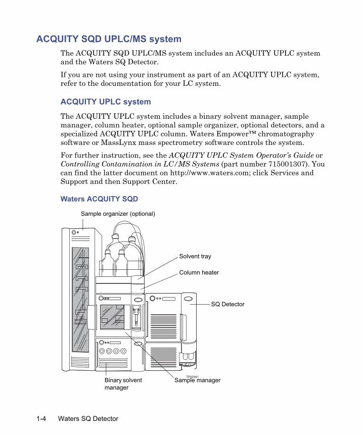
The ACQUITY SQD UPLC/MS system includes an ACQUITY UPLC system and the Waters SQ Detector.
If you are not using your instrument as part of an ACQUITY UPLC system, refer to the documentation for your LC system.
ACQUITY UPLC system
The ACQUITY UPLC system includes a binary solvent manager, sample manager, column heater, optional sample organizer, optional detectors, and a specialized ACQUITY UPLC column. WatersEmpower™ chromatography software or MassLynx mass spectrometry software controls the system.
For further instruction, see the ACQUITY UPLC System Operator’s Guide or Controlling Contamination in LC/MS Systems (part number 715001307). You can find the latter document on http://www.waters.com; click Services and Support and then Support Center.
Waters ACQUITY SQD
TP02597
Sample organizer (optional)
Solvent tray
Column heater
SQ Detector
Sample managerBinary solvent manager
1-4 Waters SQ Detector

Software and data system
The instrument is controlled by either Empower chromatography software or MassLynx mass spectrometry software. Each is a high-performance application that acquires, analyzes, manages, and distributes ultraviolet (UV), evaporative light scattering, analog, and mass spectrometry data.
Both Empower and MassLynx software enable these major operations:
• Configuring the instrument.
• Creating LC and MS methods that define operating parameters for a run.
• Using IntelliStart software to tune and mass calibrate the instrument.
• Running samples.
• Monitoring the run.
• Acquiring data.
• Processing data.
• Reviewing data.
• Printing data.
See Empower and MassLynx 4.1 user documentation and online Help for more information on installing and using Empower or MassLynx software.
ACQUITY UPLC Console
The ACQUITY UPLC Console is a software application with which you configure settings, monitor performance, run diagnostic tests, and maintain the system and its modules. The ACQUITY UPLC Console functions independently of Empower and MassLynx software and does not recognize or control the data systems.
See the ACQUITY UPLC System console online Help for details.
Overview 1-5

Ionization techniques and source probes
Electrospray ionization (ESI)
In electrospray ionization (ESI), a strong electrical charge is given the eluent as it emerges from a nebulizer. The droplets that compose the resultant aerosol undergo a reduction in size (solvent evaporation). As solvent continues to evaporate, the charge density increases until the droplet surfaces eject ions (ion evaporation). The ions can be singly or multiply charged. The multiply charged ions are of particular interest because the instrument separates them according to their mass-to-charge ratios (m/z), permitting the detection of high-molecular-weight compounds.
The instrument can accommodate eluent flow rates of up to 1 mL/min.
Combined ESI and APCI (ESCi)
Combined electrospray ionization and atmospheric pressure chemical ionization (ESCi) is supplied as standard equipment on the instrument. In ESCi, the standard ESI probe is used in conjunction with a corona pin to allow alternating acquisition of ESI and APCI ionization data, facilitating high throughput and wider compound coverage.
ESCi mode
RP00029
Sample cone tip
ESI probe tip
Corona pin
1-6 Waters SQ Detector

Atmospheric pressure chemical ionization
A dedicated high-performance, atmospheric-pressure, chemical ionization (APCI) probe is offered as an option.
Atmospheric pressure photoionization
Atmospheric pressure photoionization (APPI) is offered as an option. It uses photons generated by a krypton-discharge ultraviolet (UV) lamp (10.2 eV) to produce sample ions from vaporized LC eluent.
Ionization techniques and source probes 1-7

Ion optics
The instrument’s ion optics operate as follows:
1. Samples from the LC or Intellistart fluidics system are introduced at atmospheric pressure into the ionization source.
2. The ions pass through the sample cone into the vacuum system.
3. Ions are filtered according to their mass-to-charge ratio (m/z).
4. The transmitted ions are detected by the photomultiplier detection system.
5. The signal is amplified, digitized, and sent to the Empower chromatography or MassLynx mass spectrometry software.
Ion optics overview
Sample cone
Isolation valve
Z-Spray ion source Quadrupole Detector
Conversion dynodeSample inlet Transfer optics
1-8 Waters SQ Detector
MS operating modes
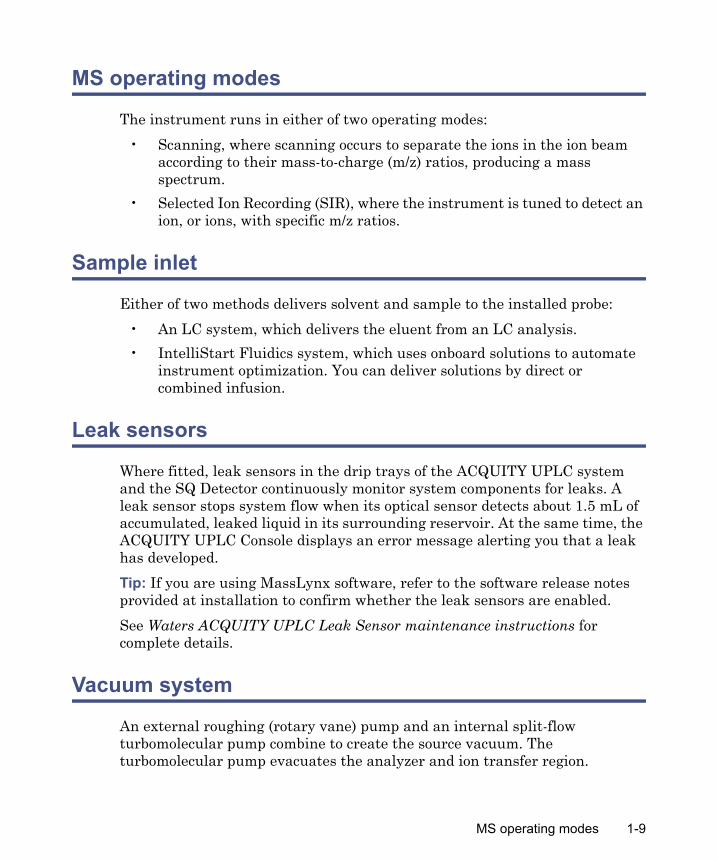
The instrument runs in either of two operating modes:
• Scanning, where scanning occurs to separate the ions in the ion beam according to their mass-to-charge (m/z) ratios, producing a mass spectrum.
• Selected Ion Recording (SIR), where the instrument is tuned to detect an ion, or ions, with specific m/z ratios.
Sample inlet
Either of two methods delivers solvent and sample to the installed probe:
• An LC system, which delivers the eluent from an LC analysis.
• IntelliStart Fluidics system, which uses onboard solutions to automate instrument optimization. You can deliver solutions by direct or combined infusion.
Leak sensors
Where fitted, leak sensors in the drip trays of the ACQUITY UPLC system and the SQ Detector continuously monitor system components for leaks. A leak sensor stops system flow when its optical sensor detects about 1.5 mL of accumulated, leaked liquid in its surrounding reservoir. At the same time, the ACQUITY UPLC Console displays an error message alerting you that a leak has developed.
Tip: If you are using MassLynx software, refer to the software release notes provided at installation to confirm whether the leak sensors are enabled.
See Waters ACQUITY UPLC Leak Sensor maintenance instructions for complete details.
Vacuum system
An external roughing (rotary vane) pump and an internal split-flow turbomolecular pump combine to create the source vacuum. The turbomolecular pump evacuates the analyzer and ion transfer region.
MS operating modes 1-9

Vacuum leaks and electrical or vacuum pump failures cause vacuum loss, which protective interlocks guard against. The system monitors turbomolecular pump speed and continuously measures vacuum pressure with a built-in Pirani gauge. The gauge also serves as a switch, stopping operation when it senses vacuum loss.
A vacuum isolation valve isolates the source from the mass analyzer, allowing routine source maintenance without venting.
Rear panel
The following figure shows the rear panel locations of the connectors used to operate the instrument with external devices.
RP00001
01757 U.S.A.
!
!
V ~ 200 - 240V ~ 200 - 240Hz 50 - 60Hz 50 - 60VVA 900
ACN 065444751
1
2
3
4
5
6
7
8
9
10
Analog
Not used
Stop Flow
Switch 2
Ground
Ground
Out
Out
1
2
3
4
5
6
7
8
9
10
Inject S tart
Event
Switch 3
Switch 4
Ground
Ground
In
In
Out
OutOut
RS 232RS 232
ETHERNETETHERNET
API GasAPI Gas6.9 Bar Maximum6.9 Bar Maximum
SOURCE VENTSOURCE VENTVACUUMVACUUM
VACUUMVACUUM
PUMPPUMP
Serial Number
Event inputs and outputs
Shielded Ethernet
Roughing pump relay switch
Source vacuum
Power cord
Source vent
Turbo vacuum
Nitrogen inlet
1-10 Waters SQ Detector

IntelliStart Fluidics system overview
The IntelliStart Fluidics system is built into the instrument. The system delivers sample directly to the MS probe in one of two ways:
• From the LC column.
• From two integral reservoirs.
Tip: The integral reservoirs can also deliver sample through direct or combined infusion to enable optimization at analytical flow rates.
The system incorporates a multi-position valve with these attributes:
• An input connection from an external LC column.
• An input connection from the instrument’s infusion syringe. (The infusion syringe is also connected to two reservoirs, A and B. In the software, you specify which reservoir to draw from.)
• An output connection to the probe.
• An output connection to a waste line.
IntelliStart Fluidics system
Column
LC
LC Waste
Probe
Syringe
Idle
Reservoir A Reservoir B
Off
Off
B
A
IntelliStart Fluidics system overview 1-11

IntelliStart Fluidics system operation
Control of solvent and sample delivery during auto-tuning, auto-calibration, and method development is automatically performed by the software.
IntelliStart Fluidics configuration requirements can be set in the system console. You can edit the parameters, frequency, and extent of the automation you want IntelliStart to perform. See the instrument’s online Help for further details.
Operating the IntelliStart Fluidics system
To enable system controls (Empower only)
1. In the ACQUITY UPLC Console system tree, expand SQ Detector.
2. Click Interactive Fluidics.
3. Click Control .
1-12 Waters SQ Detector

To set the infusion flow rate
1. In the console window, click the current flow rate.
2. In the Set Flow Rate dialog box, enter a new flow rate.
3. Click OK.
To select the reservoir
1. In the console window, click the highlighted reservoir bottle designation—A or B.
2. In the Select Reservoir dialog box, click A or B.
3. Click OK.
Tip: If the selected reservoir is different from the current reservoir, the system purges as the reservoir changes.
To select the flow state
1. In the console window, click the diverter valve position label.
2. In the Select Flow State dialog box, select the required flow state:
• Infusion – The flow goes from the syringe to the probe, and the LC flow goes to waste.
• Combined – The syringe and LC flows both go to the probe.
• LC – The flow goes from the LC to the probe, and the syringe flow goes to waste.
• Waste – All flow goes to the waste bottle.
3. Click OK.
To start the infusion syringe flow
In the console window, click . A status bar indicates the amount of fluid in the syringe and the amount of time remaining before the fluid empties. When the syringe is empty, the system becomes idle.
To refill the infusion syringe
In the console window, click .
IntelliStart Fluidics system operation 1-13

To purge the infusion syringe
In the console window, click . For further details, see “Purging the infusion syringe” on page 2-11.
To stop the current action
In the console window, click .
To disable the fluidics system controls (Empower only)
In the console window, click Control .
Operating the IntelliStart Fluidics system from the Tune window
To operate the system
1. In the ACQUITY UPLC Console system tree, click SQ Detector.
2. Click Tune .
3. In the SQ Detector Tune window, click the Fluidics tab.
4. Set the Flow Control parameters according to the instructions in the Empower or MassLynx online Help.
Programming an MS method to operate the IntelliStart Fluidics system
In the MS instrument method, you can program the operation of the system’s multi-position valve to infuse sample during a run. The valve can also divert LC flow to waste as a timed event.
To program the MS instrument method using MassLynx software
1. In the MassLynx window, click MS Method.
2. In the MS Methods window, click Options > Method Events.
1-14 Waters SQ Detector

3. In the Method events dialog box, select the desired flow state, as indicated by the following table.
Tip: At the time you power-on the instrument, the LC state is “waste”.
For further instruction, see the MassLynx online Help topic “Advanced Methods and Events”.
To program the MS instrument method using Empower software
1. In the Empower Pro interface click Run Samples, select your system, and then click OK.
2. In the Run Samples window, click Edit > Instrument Method.
3. In the instrument method editor, click the button representing your MS instrument.
4. Click Events.
Flow states and results
Flow state setting LC flows to Syringe flows to
LC SQ probe Waste
Combined SQ probe SQ probe
Infusion Waste SQ Probe
Waste Waste Waste
No change No change No change
IntelliStart Fluidics system operation 1-15

5. On the Events tab, select the desired flow path, as indicated by the following table.
Tip: At the time you power-on the instrument, the LC state is “waste”.
For further instruction, see the Empower online Help topic “Configuring events”.
Flow paths and results
Flow path setting LC flows to Syringe flows to
LC SQ probe Waste
Combined SQ probe SQ probe
Infusion Waste SQ Probe
Waste Waste Waste
No change No change No change
1-16 Waters SQ Detector

2 Preparing for Operation
This chapter describes how to start and shut-down the instrument.
Contents
Topic Page
Starting the instrument 2-2
Preparing the IntelliStart Fluidics system 2-6
Rebooting the instrument 2-12
Shutting down the instrument 2-13
2-1

Starting the instrument
The Waters SQ Detector is designed for compatibility with the ACQUITY UPLC system. If you are not using an ACQUITY UPLC system, refer to the documentation relevant to the system being used.
Starting the instrument entails powering-on the ACQUITY workstation, logging into the workstation, powering-on the SQ Detector and all the other ACQUITY instruments and devices, and starting the Empower or MassLynx software.
Requirement: You must power-on and log in to the ACQUITY workstation first to ensure that it obtains the IP addresses of the system instruments.
To start the instrument
1. Ensure the nitrogen supply is connected to the instrument’s API gas connection.
Requirement: The nitrogen must be dry and oil-free, with a purity of at least 95%. Regulate the supply at 600 to 690 kPa (6.0 to 6.9 bar, 90 to 100 psi).
For more information on connections, see the figure “The following figure shows the rear panel locations of the connectors used to operate the instrument with external devices.” on page 1-10.
2. Power-on the ACQUITY UPLC system workstation, and log in before powering-on the other instruments.
3. Press the power switch on the top, left-hand side of the instrument and ACQUITY instruments.
Caution: Using incompatible solvents can cause severe damage to the instrument. For more details, refer to the following sources:• Appendix C of the Waters SQ Detector Operator’s Guide for solvent
information.• Appendix C of the ACQUITY UPLC System Operator’s Guide for on
solvent compatibility with ACQUITY™.
Warning: During analyses that require flammable solvents, to avoid ignition of the solvents, never let the nitrogen supply pressure fall below 690 kPa (6.9 bar, 100 psi).
2-2 Preparing for Operation
Result: Each system instrument “beeps” and runs a series of startup tests.
4. Allow 3 minutes for the embedded PC to initialize.
Tip: An audible alert sounds when the PC is ready.
The power and status LEDs change as follows:
• Each system instrument’s power LED shows green.
• During initialization, the binary solvent manager’s and sample manager’s status LED flashes green.
• After the instruments are successfully powered-on, all power LEDs show steady green. The binary solvent manager’s flow LED, the sample manager’s run LED, and the SQ Detector’s Operate LED remain off.
5. Start Empower or MassLynx software.
Tip: You can monitor the ACQUITY Console for messages and LED indications.
6. Launch IntelliStart using one of the following methods.
• MassLynx – In the MassLynx main window’s lower left-hand corner, click IntelliStart.
• Empower – In the Run Samples window, right-click the SQ Detector’s control panel, and then click Launch Intellistart.
Result: The SQ Detector’s console appears. The instrument is in Standby mode.
7. Click Control > Pump to start the roughing pump. The Operate LED remains off.
Tip: There is a 20-second delay, during which the turbopump is starting, before the roughing pump starts. IntelliStart displays “Instrument in standby”.
8. Click Resolve or Operate to put the instrument into Operate mode. When the instrument is in good operating condition, IntelliStart displays “Ready”.
Tip: Clicking Resolve prepares the system for operation, putting the instrument into Operate mode. If clicking Resolve fails to put the instrument into Operate mode, IntelliStart displays corrective actions.
Starting the instrument 2-3

Configuring IntelliStart
To configure IntelliStart
1. In the ACQUITY UPLC Console system tree, expand SQ Detector.
2. Click IntelliStart.
3. Click Configure > IntelliStart Configuration.
4. In the IntelliStart Configuration dialog box, in the Checks list, select the check boxes for the items you want checked during SQ Detector startup. Clear the check boxes of items you do not want checked.
Tip: To display detailed information for an item, highlight it and then click Properties.
5. Click OK.
Verifying the instrument’s state of readiness
When the instrument is in good operating condition, the power and Operate LEDs show constant green. You can view any error messages in IntelliStart.
To access IntelliStart
1. In the ACQUITY UPLC Console system tree, expand SQ Detector.
2. Click IntelliStart.
Tuning and calibration information
The instrument must be tuned and calibrated prior to use, tasks normally performed from IntelliStart.
For further instruction, see the instrument’s online Help topic “Instrument Setup” and Chapter 4, “Operating the Instrument”.
2-4 Preparing for Operation

Running the instrument at high flow rates
ACQUITY UPLC is run at high flow rates. To optimize desolvation, and thus sensitivity, you must run the ACQUITY SQD system at appropriate gas flows and desolvation temperatures. IntelliStart automatically sets these parameters when you enter a flow rate, according to the following table.
Note: Under low ambient temperature, high moisture, and high flow rate conditions, condensation can occur in the instrument’s source.
Monitoring the instrument LEDs
Light-emitting diodes on the instrument indicate its operational status.
Power LED
The power LED, to the top, left-hand side of the instrument’s front panel, indicates when the instrument is powered-on or powered-off.
Operate LED
The Operate LED, on the right-hand side of the power LED, indicates the operating condition.
See the instrument’s online Help topic “Monitoring the detector LEDs” for details of the Operate LED indications.
Flow rate versus temperature and gas flow
Flow rate (mL/min)
Source temp (°C)Desolvation temp (°C)
Desolvation gas flow (L/h)
0.000 to 0.100 150 250 500
0.101 to 0.300 150 350 600
0.301 to 0.500 150 400 800
>0.500 150 0 00
Starting the instrument 2-5

Preparing the IntelliStart Fluidics system
Installing the solvent manifold drip tray
Required material
Chemical-resistant, powder-free gloves
To install the solvent manifold drip tray
Install the solvent manifold drip tray as shown below:
Warning: The solvent manifold drip tray can be contaminated with biohazardous and/or toxic materials. Always wear chemical-resistant, powder-free gloves while performing this procedure.
TP02685
2-6 Preparing for Operation

Installing the reservoir bottles
An optional Low-volume Adaptor Kit is available for infusing smaller volumes. The low-volume vials have a volume of 1.5 mL.
Required material
Chemical-resistant, powder-free gloves
To install the reservoir bottles
1. Remove the reservoir bottle caps.
2. Screw the reservoir bottles onto the instrument, as shown below.
To install low-volume vials
1. If a standard reservoir bottle is fitted, remove the reservoir bottle.
2. Screw the low-volume adaptor into the manifold and tighten it finger-tight.
Warning: The reservoir bottles can be contaminated with biohazardous and/or toxic materials. Always wear chemical-resistant, powder-free gloves while performing this procedure.
Warning: The reservoir bottles can be contaminated with biohazardous and/or toxic materials. Always wear chemical-resistant, powder-free gloves while performing this procedure.
TP02630
Preparing the IntelliStart Fluidics system 2-7

3. Screw the low-volume vial into the adaptor.
Diverter valve positions
Column and syringe in home position after power-up
After power-up, the flow path between the column and waste is open. The syringe is empty, and the flow path between it and waste is open.
TP02630
Column
Waste
LC Waste
Probe
Syringe
Idle
Reservoir A Reservoir B
Off
Off
B
A
2-8 Preparing for Operation

LC position
In the LC position, the flow path between the LC and probe is open, and the flow path between the syringe and waste is also open.
Infusion position
Column
LC
LC Waste
Probe
Syringe
Idle
Reservoir A Reservoir B
Off
Off
B
A
Column
Infusion
LC Waste
Probe
Syringe
Reservoir A Reservoir B
Off
On
B
A
Infusion
Preparing the IntelliStart Fluidics system 2-9

Combined position with LC flow and syringe in idle mode
Waste position
In the waste position, both the LC flow and the infusion syringe flow are directed to waste. The syringe mode can be only static or dispensing (that is, never drawing).
Column
Combined
LC Waste
Probe
Syringe
Reservoir A Reservoir B
Off
Off
B
A
Idle
Column
Waste
LC Waste
Probe
Syringe
Reservoir A Reservoir B
Off
Off
B
A
Idle
2-10 Preparing for Operation

Purging the infusion syringe
Whenever you replace a solution bottle, purge the infusion syringe with the solution that you are going to use next.
Tip: Depending on the solutions used, the IntelliStart Fluidics system can require more than one purge cycle to minimize carryover.
To purge the infusion syringe
1. In the ACQUITY UPLC Console system tree, expand SQ Detector.
2. If you use MassLynx software, click Interactive Display; otherwise click Interactive Fluidics.
3. If you use Empower software, click Control .
4. Select the required solution reservoir.
5. Click to purge the system.
Tip: System purge takes approximately 2 minutes and uses a total volume of 800 µL.
Preparing the IntelliStart Fluidics system 2-11

Rebooting the instrument
Reboot the instrument when any of these conditions applies
• The Tune window fails to respond.
• Empower or MassLynx software fails to initialize.
• Immediately following a software upgrade.
Rebooting the instrument by pressing the reset button
The reset button shuts down the electronics momentarily and causes the instrument to reboot.
To reboot the instrument by pressing the reset button
1. Open the instrument’s front, left-hand door.
2. Press the red, reset button at the top, left-hand side of the instrument.
NEBULIZERNEBULIZERDESOLVATIONDESOLVATION
POW ER OPERATE
RP00026
Reset button
2-12 Preparing for Operation

Shutting down the instrument
Recommendation: Leave the instrument in Operate mode except when performing routine maintenance.
If you must shut down the instrument, refer to the instructions in this section.
Tip: Set system shutdown parameters in the shutdown editor. Consult the MassLynx online Help for more information.
Putting the instrument in Standby mode for overnight shutdown
To put the instrument in Standby mode overnight
1. Ensure that there is sufficient capacity in the waste container for the LC flow that is to be diverted to waste (see Appendix B of the Waters SQ Detector Operator’s Guide).
2. In the ACQUITY UPLC Console, click to stop the LC flow or, if column flow is required, divert the LC flow to waste as follows:
a. In the ACQUITY UPLC Console system tree, expand SQ Detector.
b. If you use MassLynx software, click Interactive Display; otherwise click Interactive Fluidics.
c. If you use Empower software, click Control .
d. Click the current diverter valve position label.
e. In the Select a Flow State dialog box, select Waste.
f. Click OK.
3. Click Standby to shut off heaters and voltages.
Tip: You can create a method to stop the gas flow or lower the temperature. See the Empower or MassLynx online Help for more information on creating methods.
Caution: Buffers left in the system can precipitate and damage instrument components.
Shutting down the instrument 2-13

Complete instrument shutdown
To completely shut down the instrument
1. Put the instrument in Standby mode (see “Putting the instrument in Standby mode for overnight shutdown” on page 2-13).
2. In the ACQUITY UPLC Console, click API .
3. Click Control > Vent.
Result: The turbomolecular pump is switched off. When the turbomolecular pump runs down to half its normal operating speed, the vent valve opens and the instrument is automatically vented. The Operate LED changes from green to red and then turns off.
4. Exit MassLynx or Empower software.
5. After the roughing pump shuts off, operate the power button (on the front of the instrument) to power-off the instrument.
6. Disconnect the power cable from the back of the instrument.
7. Power-off all other instruments and the workstation.
Note: The fans inside some instruments run continuously, even after you power-off the instruments.
Warning: The SQ Detector’s power switch does not isolate the instrument from the main power supply. To isolate the instrument, you must disconnect the power cable from the back of the instrument.
2-14 Preparing for Operation

Emergency instrument shutdown
To shut down the instrument in an emergency
1. Operate the power button on the front of the instrument.
2. Disconnect the power cable from the back of the instrument.
Warning: The SQ Detector’s power switch does not isolate the instrument from the main power supply. To isolate the instrument, you must disconnect the power cable from the back of the instrument.
Caution: Data can be lost during an emergency shutdown.
Shutting down the instrument 2-15

2-16 Preparing for Operation

3 ESI and ESCi Modes of Operation
This chapter describes how to prepare the instrument for the following modes of operation:
• ESI (electrospray ionization).
• ESCi (combined electrospay and atmospheric pressure chemical ionization).
If your system uses APCI mode, see Chapter 6, “Optional APCI Mode of Operation”.
Contents
Topic Page
Introduction 3-2
Installing the ESI probe 3-2
Installing the corona pin 3-5
Optimizing the ESI probe for ESCi operation 3-8
Removing the corona pin 3-9
Removing the ESI probe 3-10
3-1

Introduction
The ESI and ESCi ionization mode options use the standard ESI probe that is fitted to the instrument when it is shipped from the factory. For ESCi operation, the corona pin is used in conjunction with the ESI probe. The following sections explain how to install and remove the ESI probe and corona pin.
For further instruction, see “Electrospray ionization (ESI)” on page 1-6 and “Combined ESI and APCI (ESCi)” on page 1-6.
Installing the ESI probe
Required material: Chemical-resistant, powder-free gloves
To install the ESI probe
1. Prepare the instrument for working on the source (see The Waters SQ Detector Operator’s Guide).
2. Open the instrument’s access door.
3. Remove the protective sleeve, if fitted, from the ESI probe tip.
Warning: The ACQUITY UPLC system connections, ESI probe, and source can be contaminated with biohazardous and/or toxic materials. Always wear chemical-resistant, powder-free gloves while performing this procedure.
Warning: To avoid electric shock, ensure that the instrument is suitably prepared before commencing this procedure.
Warning: The source can be hot. To avoid burn injuries, take great care while working with the instrument’s access door open.
Warning: The ESI probe tip is sharp. To avoid puncture wounds, handle the ESI probe with care.
3-2 ESI and ESCi Modes of Operation

4. Ensure that the contacts on the ESI probe align with the probe adjuster assembly contacts, and carefully slide the ESI probe into the hole in the probe adjuster assembly.
5. Secure the ESI probe by tightening the 2 thumbscrews.
TP02632
ESI probe
Probe adjuster assembly contacts
Probe adjuster assembly
Installing the ESI probe 3-3

ESI probe mounted on the source enclosure, showing the connections
6. Connect the ESI probe’s PTFE tube to the nebulizer gas connection.
7. Ensure that the probe adjuster assembly’s electrical lead is connected to the instrument’s probe connection.
8. Connect the ESI probe’s electrical lead to the instrument’s HV connection.
9. Using tubing greater than or equal to 0.004-inch (ID), connect the diverter valve to the ESI probe.
Tip: Two tubes of different ID are supplied with the instrument.
Requirement: If you are replacing the tubing supplied with the instrument, you must minimize the length of the tube connecting the diverter valve to the ESI probe. Doing so minimizes delays and dispersion.
10. Close the instrument’s access door.
Warning: To avoid electric shock, do not use stainless steel tubing to connect the diverter valve to the ESI probe; use the PEEK™ tubing supplied with the instrument.
NEBULIZERNEBULIZER
APPIAPPI
PROBEPROBE
HVHV
DESOLVATIONDESOLVATION
POWERPOWER OPERATEOPERATE
RP00017
Thumbscrew
ESI probe
Nebulizer gas connection
Desolvation gasconnection
Probe adjuster assembly
ESI probe electrical lead
Probe adjuster assembly electrical lead
Vernier probe adjuster
Diverter valve
3-4 ESI and ESCi Modes of Operation

Installing the corona pin
Required materials:
• Chemical-resistant, powder-free gloves
• Needle-nose pliers
To install the corona pin
1. In the ACQUITY UPLC Console, click Standby , and confirm that the Operate indicator is not illuminated.
2. Open the instrument’s access door.
3. Open the source enclosure door by releasing both spring-clips and lowering the door towards you.
4. Use the needle-nose pliers to remove the blanking plug from the corona pin mounting contact. Store the blanking plug in a safe location.
Warning: The ACQUITY UPLC system connections, ESI probe, and source can be contaminated with biohazardous and/or toxic materials. Always wear chemical-resistant, powder-free gloves while performing this procedure.
Warning: To avoid electric shock, ensure that the instrument is in Standby mode when commencing this procedure.
Warning: The source can be hot. To avoid burn injuries, take great care while working with the instrument’s access door open.
Warning: The probe tip is sharp. To avoid puncture wounds, take great care while working with the source enclosure door open if an ESI probe is fitted.
Caution: Do not apply any downward force to the source enclosure door while the door is open.
Installing the corona pin 3-5

Corona pin mounting contact
5. Use the needle-nose pliers to fit the corona pin to the mounting contact.
Requirement: Ensure that the corona pin is securely mounted and that its tip aligns with the sample cone aperture.
Warning: The corona pin tip is sharp. To avoid puncture wounds, handle the corona pin with care.
Caution: To avoid damaging to the corona pin’s tip and bending the pin, use the needle-nose pliers to grip the corona pin at the end that fits into the mounting contact.
RP00028RP00028
Corona pin mounting contact blanking plug
3-6 ESI and ESCi Modes of Operation

Source, showing the corona pin, ESi probe tip, and sample cone
6. Use the vernier probe adjuster to position the ESI probe tip so that it is pointing approximately midway between the tips of the sample cone and corona pin. (See the figure page 3-4.)
7. Close the source enclosure door, and secure it with both spring-clips.
8. Close the instrument’s access door.
RP00029
Corona pin
Sample cone tip
ESI probe tip
Installing the corona pin 3-7

Optimizing the ESI probe for ESCi operation
Required material: 80:20 acetonitrile/water
To optimize the ESI probe for ESCi operation
1. In the ACQUITY UPLC Console, click SQ Detector, and then click Tune
.
2. In the Tune window, click Setup > Inter-scan Setup.
3. In the Inter-scan Setup dialog box, click Reset to Defaults.
4. Click OK.
5. In the Tune window, click Ion Mode > ESCi+.
6. Select box numbers 1 and 2, clear box numbers 3 and 4 (above the peak display).
7. In row 1, set Ion Mode to ES.
8. In row 2, set Ion Mode to APCI.
9. In each row, set Mass to 42 and Span to 5.
10. Start an infusion of 80:20 acetonitrile/water.
11. Use the vernier probe adjuster to ensure that the ESI probe tip is pointing approximately midway between the tips of the sample cone and corona pin.
12. In the Tune window, observe the 42 Da peak in the ES+ and APCI+ peak displays, and increase the values of Capillary (kV) and Corona [(µA) in the current mode or kV in the voltage mode] to produce the most intense ESI+ and APCI+ signal.
13. Use the vernier probe adjuster to gradually move the probe bi-directionally to determine the best position for both the ESI+ and APCI+ signals.
14. To determine whether you have discrete ionization in the ESI or APCI mode, set the Capillary parameter to 0 kV and observe that little or no
3-8 ESI and ESCi Modes of Operation

signal remains in ESI mode. Then set the Corona parameter to 0 µA or 0 kV, and observe that little or no signal remains in APCI mode.
Result: The ESI probe is now optimized for ESCi mode.
Tip: If necessary, repeat the above procedure using the analyte of interest, because ionization potentials can vary with different samples.
Removing the corona pin
Required materials:
• Chemical-resistant, powder-free gloves
• Needle-nose pliers
To remove the corona pin
1. In the ACQUITY UPLC Console, click Standby , and confirm that the Operate indicator is not illuminated.
2. Open the instrument’s access door.
3. Open the source enclosure door by releasing both spring-clips and lowering the door towards you.
Warning: The ACQUITY UPLC system connections, corona pin, ESI probe, and source can be contaminated with biohazardous and/or toxic materials. Always wear chemical-resistant, powder-free gloves while performing this procedure.
Warning: To avoid electric shock, ensure that the instrument is in Standby mode when commencing this procedure.
Warning: The source can be hot. To avoid burn injuries, take great care while working with the instrument’s access door open.
Warning: The probe tip is sharp. To avoid puncture wounds, take great care while working with the source enclosure door open if an ESI probe is fitted.
Caution: Do not apply any downward force to the source enclosure door while the door is open.
Removing the corona pin 3-9

4. Use the needle-nose pliers to remove the corona pin from its mounting
contact. Store the corona pin in a safe location. (See the figure “Source, showing the corona pin, ESi probe tip, and sample cone” on page 3-7.)
5. Use the needle-nose pliers to fit the blanking plug to the corona pin mounting contact. (See the figure “Corona pin mounting contact” on page 3-6.)
6. Close the source enclosure door, and secure it with both spring-clips.
7. Close the instrument’s access door.
Removing the ESI probe
Required material: Chemical-resistant, powder-free gloves
To remove the ESI probe
1. Prepare the instrument for working on the source (see the Waters SQ Detector Operator’s Guide).
2. Open the instrument’s access door.
Warning: The corona pin tip is sharp. To avoid puncture wounds, handle the corona pin with care.
Caution: To avoid damaging to the corona pin’s tip and bending the pin, use the needle-nose pliers to grip the corona pin at the end that fits into the mounting contact.
Warning: The ACQUITY UPLC system connections, ESI probe, and source can be contaminated with biohazardous and/or toxic materials. Always wear chemical-resistant, powder-free gloves while performing this procedure.
Warning: To avoid electric shock, ensure that the instrument is suitably prepared before commencing this procedure.
Warning: The ESI probe and source can be hot. To avoid burn injuries, take great care while working with the instrument’s access door open.
3-10 ESI and ESCi Modes of Operation

3. Disconnect the diverter valve tubing from the ESI probe.
4. Disconnect the ESI probe’s electrical lead from the high voltage connection.
5. Ensure that the API gas is turned off.
6. Disconnect the ESI probe’s PTFE tube from the nebulizer gas connection.
7. Undo the 2 thumbscrews securing the ESI probe to the probe adjuster assembly.
8. Carefully remove the ESI probe from the probe adjuster assembly.
9. If available, fit the protective sleeve to the ESI probe tip.
10. Close the instrument’s access door.
Warning: The ESI probe tip is sharp. To avoid puncture wounds, handle the probe with care.
Removing the ESI probe 3-11

3-12 ESI and ESCi Modes of Operation

4 Operating the Instrument
This chapter is an introduction to operating your instrument; it explains these tasks:
• Setting-up your instrument.
• Performing a sample tune.
• Developing instrument methods.
• Verifying the system.
Contents
Topic Page
Setting-up the instrument 4-2
Performing a sample tune 4-6
Developing experiment methods 4-7
Verifying the system 4-10
4-1

Setting-up the instrument
The IntelliStart instrument setup calibrates the instrument and then, by default, performs a sample tune. If calibration is unnecessary, you can perform only a sample tune (see “Performing a sample tune” on page 4-6).
In the following example, sodium cesium iodide is used as the calibrant solution and sulfadimethoxine is used as the tune sample.
Tips:
• You can substitute solutions suitable for your requirements.
• Instrument setup need only be performed every 3 to 6 months, depending on your usage requirements.
See the instrument’s online Help for further details of IntelliStart.
Requirement: If you use Empower software, your project must contain the instrument methods supplied during installation of the SQ Detector software. See the Empower online Help for further details on restoring projects.
Required materials:
• Sodium cesium iodide solution (2 ng/µL)
• Sulfadimethoxine solution (100 pg/µL)
To prepare the IntelliStart Fluidics system
Requirement: Ensure that there is enough solution in each reservoir for approximately 5 minutes of operation after purging the reservoirs.
Recommendation: In general, place calibrant solution in reservoir A and sample solution in reservoir B.
1. Ensure that IntelliStart Fluidics system’s reservoir A is filled with sodium cesium iodide solution.
2. Ensure that reservoir B is filled with sulfadimethoxine solution.
3. Launch the ACQUITY UPLC Console using one of the following methods.
• MassLynx – In the MassLynx main window, click MS Console.
• Empower – In the Run Samples window, right-click the SQ Detector’s control panel, and then click Launch Instrument Console.
4-2 Operating the Instrument

4. In the ACQUITY UPLC Console system tree, expand SQ Detector.
5. If you use MassLynx software, click Interactive Display; otherwise click Interactive Fluidics.
6. If the calibration reservoir is selected, click to purge the system.
Tip: System purge takes approximately 2 minutes.
7. If the sample reservoir is selected, click on the reservoir display and in the Select Reservoir dialog box, select the calibration reservoir.
8. Click OK.
Result: The calibration reservoir is selected, and the system is purged.
To specify the instrument set-up parameters
1. In the ACQUITY UPLC Console system tree, click SQ Detector.
2. Ensure that Ion Mode is ES+.
3. Click IntelliStart.
4. Ensure that Instrument Setup is selected.
5. If you require system pre-checking, select Pre-checks.
Rationale: If Pre-checks is selected, when IntelliStart starts the instrument setup, it determines whether the existing calibration is still valid. If so, it does not perform a full calibration but proceeds to sample tuning the instrument.
For further details, see the instrument’s online Help topic “IntelliStart flow diagram”.
6. Click Start to open the IntelliStart Setup Parameters dialog box.
7. In the Instrument Setup tab’s Reference list, click Naics.
Rationale: Naics is the calibration reference for sodium cesium iodide when working in ES+ ion mode.
Setting-up the instrument 4-3

8. If you use MassLynx software, click “Fill from reference file”; otherwise, click “Get Reference Masses”.
Result: The default mass values appear in the Instrument Tune Masses text boxes.
Rule: You must click “Fill from reference file” or “Get Reference Masses” to obtain the masses from the reference each time you select a new calibration reference.
Tip: You can use alternative reference solutions to calibrate at different masses.
9. The tune and calibration results are saved with the names specified. You can use the default names or enter your own.
To specify the sample tune parameters using MassLynx software
This procedure applies only if you are using MassLynx software. If you are using Empower software, see “To specify the sample tune parameters using Empower software” on page 4-4.
1. In the IntelliStart Setup Parameters dialog box, click the Sample Tune tab.
2. For the first sample tune mass, select the check box and enter a value of 311.
3. Clear all the check boxes for other sample tune masses.
4. In the Tune text box, enter sulfadimethoxine.ipr.
Rationale: The sample tune results are written to this file.
To specify the sample tune parameters using Empower software
This procedure applies only if you are using Empower software. If you are using MassLynx software, see “To specify the sample tune parameters using MassLynx software” on page 4-4.
1. In the IntelliStart Setup Parameters dialog box, click the Sample Tune tab.
2. For the first sample tune mass, select the check box and enter a value of 311.
4-4 Operating the Instrument

3. Clear all the check boxes for other sample tune masses.
4. In the Save Sample Tune Parameters As box, enter sulfadimethoxine.
To start instrument setup
1. Click Start.
Result: A message appears reminding you to ensure that the calibrant solutions, calibration parameters, and LC flow are set correctly.
2. Click OK.
Result: An autotune on the calibrant is followed by automatic calibration. The ACQUITY UPLC Console displays the progress of the setup.
Display during calibration
IntelliStart creates tune and calibration settings, which are saved as specified on the Instrument Setup Parameters dialog box’s Instrument Setup tab. Once calibration is complete, the sample tune starts on the mass defined in the IntelliStart Setup Parameters dialog box. When the sample tune is complete, the sample tune results are saved with the name sulfadimethoxine.
Setting-up the instrument 4-5

Performing a sample tune
In the following example, sulfadimethoxine is used as the tuning sample.
Required material: Sulfadimethoxine solution (100 pg/µL)
To perform a sample tune
1. Prepare the IntelliStart Fluidics system with sulfadimethoxine solution in reservoir B (see “To prepare the IntelliStart Fluidics system” on page 4-2).
2. In the ACQUITY UPLC Console system tree, click SQ Detector.
3. Ensure that the Ion Mode is ES+.
4. Click IntelliStart.
5. Clear the Instrument Setup check box.
6. If you require system pre-checking, select Pre-checks.
Rationale: If Pre-checks is selected, when IntelliStart starts the sample tune, it determines whether the existing tune is still valid. If so, no sample tune is performed.
See the instrument’s online Help topic “IntelliStart flow diagram”.
7. Click Start.
8. In the IntelliStart Setup Parameters dialog box’s Sample Tune tab, specify the sample tune parameters as described for your data system in “To specify the sample tune parameters using MassLynx software” on page 4-4 or “To specify the sample tune parameters using Empower software” on page 4-4.
9. Click Start.
Result: A message appears reminding you to ensure that the tune solutions, tune parameters, and LC flow are set correctly.
10. Click OK.
Result: The ACQUITY UPLC Console displays the progress of the setup. When the sample tune is complete, the sample tune results are saved with the name sulfadimethoxine.
4-6 Operating the Instrument

Developing experiment methods
IntelliStart software enables you to automatically develop quantitative SIR methods for compounds of interest. Up to four compounds can be handled in a single process. The following procedure creates a method using sulfadimethoxine as an example.
Required material: Sulfadimethoxine solution (100 pg/µL)
To create a method
1. Prepare the IntelliStart Fluidics system with sulfadimethoxine solution in reservoir B (see “To prepare the IntelliStart Fluidics system” on page 4-2).
2. In the ACQUITY UPLC Console system tree, click SQ Detector.
3. Ensure that the Ion Mode is ES+.
4. Click IntelliStart.
5. Clear the Instrument Setup check box.
6. Click Develop Method.
7. If you require system pre-checking, select Pre-checks. See the instrument’s online Help topic “IntelliStart flow diagram”.
8. Click Start.
9. In the IntelliStart Setup Parameters dialog box, click the Method Developer tab if you use MassLynx software, or the Develop Method tab if you use Empower software.
Rule: The masses, tune parameters, and IntelliStart Fluidics system parameters already set in IntelliStart are used.
10. Select the parameters shown in the following figures.
Developing experiment methods 4-7

Method Developer tab (MassLynx)
4-8 Operating the Instrument

Develop Method tab (Empower)
The dialog box above shows a method called sulfadimethoxine being created.
In MassLynx software, the validation pane selections save optimization data for validation purposes and create an autotune report file (Sulfadimethoxine.xml). In Empower software, an autotune report file is printed.
For further information on the parameters available in the Develop Method tab, see the instrument’s online Help.
Developing experiment methods 4-9

11. Click Start.
Result. A message appears reminding you to ensure that the sample solutions, sample tune parameters, and LC flow are set correctly.
12. Click OK.
Result: The ACQUITY UPLC Console displays the progress of the method development. When the method development is complete, the method settings are saved with the name Sulfadimethoxine.
A green check mark indicates a successful run; a red cross indicates a failure.
Verifying the system
Using IntelliStart, you can verify that your system is performing to an acceptable standard. You can run the system verification in one of the following three ways:
• Manually from the ACQUITY UPLC Console.
• Manually as part of an autotune sequence.
• If you use MassLynx, automatically on a scheduled time and date.
For instructions on preparing a sulfadimethoxine standard for use with the supplied LC/MS System Check projects, see “Preparing Samples for LC/MS System Check with Empower software” on page B-1.
For detailed information on setting up system verification, see the instrument’s online Help.
4-10 Operating the Instrument

A Safety Advisories
Waters instruments display hazard symbols designed to alert you to the hidden dangers of operating and maintaining the instruments. Their corresponding user guides also include the hazard symbols, with accompanying text statements describing the hazards and telling you how to avoid them. This appendix presents all the safety symbols and statements that apply to the entire line of Waters products.
Contents
Topic Page
Warning symbols A-2
Caution symbol A-5
Warnings that apply to all Waters instruments A-5
Electrical and handling symbols A-11
A-1

Warning symbols
Warning symbols alert you to the risk of death, injury, or seriously adverse physiological reactions associated with an instrument’s use or misuse. Heed all warnings when you install, repair, and operate Waters instruments. Waters assumes no liability for the failure of those who install, repair, or operate its instruments to comply with any safety precaution.
Task-specific hazard warnings
The following warning symbols alert you to risks that can arise when you operate or maintain an instrument or instrument component. Such risks include burn injuries, electric shocks, ultraviolet radiation exposures, and others.
When the following symbols appear in a manual’s narratives or procedures, their accompanying text identifies the specific risk and explains how to avoid it.
Warning: (General risk of danger. When this symbol appears on an instrument, consult the instrument’s user documentation for important safety-related information before you use the instrument.)
Warning: (Risk of burn injury from contacting hot surfaces.)
Warning: (Risk of electric shock.)
Warning: (Risk of fire.)
Warning: (Risk of needle puncture.)
Warning: (Risk of injury caused by moving machinery.)
Warning: (Risk of exposure to ultraviolet radiation.)
Warning: (Risk of contacting corrosive substances.)
Warning: (Risk of exposure to a toxic substance.)
Warning: (Risk of personal exposure to laser radiation.)
A-2 Safety Advisories

Warnings that apply to particular instruments, instrument components, and sample types
The following warnings can appear in the user manuals of particular instruments and on labels affixed to them or their component parts.
Burst warning
This warning applies to Waters instruments fitted with nonmetallic tubing.
Mass spectrometer flammable solvents warning
This warning applies to instruments operated with flammable solvents.
Warning: (Risk of exposure to biological agents that can pose a serious health threat.)
Warning: Pressurized nonmetallic, or polymer, tubing can burst. Observe these precautions when working around such tubing:• Wear eye protection.• Extinguish all nearby flames.• Do not use tubing that is, or has been, stressed or kinked.• Do not expose nonmetallic tubing to incompatible compounds like
tetrahydrofuran (THF) and nitric or sulfuric acids.• Be aware that some compounds, like methylene chloride and
dimethyl sulfoxide, can cause nonmetallic tubing to swell, which significantly reduces the pressure at which the tubing can rupture.
Warning: Where significant quantities of flammable solvents are involved, a continuous flow of nitrogen into the ion source is required to prevent possible ignition in that enclosed space. Ensure that the nitrogen supply pressure never falls below 690 kPa (6.9 bar, 100 psi) during an analysis in which flammable solvents are used. Also ensure a gas-fail connection is connected to the LC system so that the LC solvent flow stops if the nitrogen supply fails.
Warning symbols A-3

Mass spectrometer shock hazard
This warning applies to all Waters mass spectrometers.
This warning applies to certain instruments when they are in Operate mode.
Biohazard warning
This warning applies to Waters instruments that can be used to process material that might contain biohazards: substances that contain biological agents capable of producing harmful effects in humans.
Warning: To avoid electric shock, do not remove the mass spectrometer’s protective panels. The components they cover are not user-serviceable.
Warning: High voltages can be present at certain external surfaces of the mass spectrometer when the instrument is in Operate mode. To avoid non-lethal electric shock, make sure the instrument is in Standby mode before touching areas marked with this high voltage warning symbol.
Warning: Waters's instruments and software can be used to analyze or process potentially infectious human-sourced products, inactivated microorganisms, and other biological materials. To avoid infection with these agents, assume that all biological fluids are infectious, observe Good Laboratory Practices and, consult your organization’s biohazard safety representative regarding their proper use and handling. Specific precautions appear in the latest edition of the US National Institutes of Health (NIH) publication, Biosafety in Microbiological and Biomedical Laboratories (BMBL).
A-4 Safety Advisories

Chemical hazard warning
This warning applies to Waters instruments that can process corrosive, toxic, flammable, or other types of hazardous material.
Caution symbol
The caution symbol signifies that an instrument’s use or misuse can damage the instrument or compromise a sample’s integrity. The following symbol and its associated statement are typical of the kind that alert you to the risk of damaging the instrument or sample.
Warnings that apply to all Waters instruments
When operating this device, follow standard quality control procedures and the equipment guidelines in this section.
Warning: Waters instruments can be used to analyze or process potentially hazardous substances. To avoid injury with any of these materials, familiarize yourself with the materials and their hazards, observe Good Laboratory Practices (GLP), and consult your organization’s safety representative regarding proper use and handling. Guidelines are provided in the latest edition of the National Research Council's publication, Prudent Practices in the Laboratory: Handling and Disposal of Chemicals.
Caution: To avoid damage, do not use abrasives or solvents to clean the instrument’s case.
Caution symbol A-5

Attention: Changes or modifications to this unit not expressly approved by the party responsible for compliance could void the user’s authority to operate the equipment.
Important: Toute modification sur cette unité n’ayant pas été expressément approuvée par l’autorité responsable de la conformité à la réglementation peut annuler le droit de l’utilisateur à exploiter l’équipement.
Achtung: Jedwede Änderungen oder Modifikationen an dem Gerät ohne die ausdrückliche Genehmigung der für die ordnungsgemäße Funktionstüchtigkeit verantwortlichen Personen kann zum Entzug der Bedienungsbefugnis des Systems führen.
Avvertenza: qualsiasi modifica o alterazione apportata a questa unità e non espressamente autorizzata dai responsabili per la conformità fa decadere il diritto all'utilizzo dell'apparecchiatura da parte dell'utente.
Atencion: cualquier cambio o modificación efectuado en esta unidad que no haya sido expresamente aprobado por la parte responsable del cumplimiento puede anular la autorización del usuario para utilizar el equipo.
注意:未經有關法規認證部門允許對本設備進行的改變或修改,可能會使使用者喪失操作該設備的權利。
注意:未经有关法规认证部门明确允许对本设备进行的改变或改装,可能会使使用者丧失操作该设备的合法性。
주의: 규정 준수를 책임지는 당사자의 명백한 승인 없이 이 장치를 개조 또는 변경할 경우, 이 장치를 운용할 수 있는 사용자 권한의 효력을 상실할 수 있습니다.
注意:規制機関から明確な承認を受けずに本装置の変更や改造を行うと、本装置のユーザーとしての承認が無効になる可能性があります。
A-6 Safety Advisories

Warning: Use caution when working with any polymer tubing under pressure:• Always wear eye protection when near pressurized polymer tubing.• Extinguish all nearby flames.• Do not use tubing that has been severely stressed or kinked.• Do not use nonmetallic tubing with tetrahydrofuran (THF) or concentrated
nitric or sulfuric acids.• Be aware that methylene chloride and dimethyl sulfoxide cause nonmetallic
tubing to swell, which greatly reduces the rupture pressure of the tubing.Attention: Manipulez les tubes en polymère sous pression avec precaution:• Portez systématiquement des lunettes de protection lorsque vous vous
trouvez à proximité de tubes en polymère pressurisés.• Eteignez toute flamme se trouvant à proximité de l’instrument.• Evitez d'utiliser des tubes sévèrement déformés ou endommagés.• Evitez d'utiliser des tubes non métalliques avec du tétrahydrofurane (THF)
ou de l'acide sulfurique ou nitrique concentré.• Sachez que le chlorure de méthylène et le diméthylesulfoxyde entraînent le
gonflement des tuyaux non métalliques, ce qui réduit considérablement leur pression de rupture.
Vorsicht: Bei der Arbeit mit Polymerschläuchen unter Druck ist besondere Vorsicht angebracht:• In der Nähe von unter Druck stehenden Polymerschläuchen stets
Schutzbrille tragen.• Alle offenen Flammen in der Nähe löschen.• Keine Schläuche verwenden, die stark geknickt oder überbeansprucht sind.• Nichtmetallische Schläuche nicht für Tetrahydrofuran (THF) oder
konzentrierte Salpeter- oder Schwefelsäure verwenden.• Durch Methylenchlorid und Dimethylsulfoxid können nichtmetallische
Schläuche quellen; dadurch wird der Berstdruck des Schlauches erheblich reduziert.
Warnings that apply to all Waters instruments A-7

Attenzione: fare attenzione quando si utilizzano tubi in materiale polimerico sotto pressione:• Indossare sempre occhiali da lavoro protettivi nei pressi di tubi di polimero
pressurizzati.• Spegnere tutte le fiamme vive nell'ambiente circostante.• Non utilizzare tubi eccessivamente logorati o piegati.• Non utilizzare tubi non metallici con tetraidrofurano (THF) o acido solforico
o nitrico concentrati.• Tenere presente che il cloruro di metilene e il dimetilsolfossido provocano
rigonfiamenti nei tubi non metallici, riducendo notevolmente la pressione di rottura dei tubi stessi.
Advertencia: se recomienda precaución cuando se trabaje con tubos de polímero sometidos a presión:• El usuario deberá protegerse siempre los ojos cuando trabaje cerca de tubos
de polímero sometidos a presión.• Si hubiera alguna llama las proximidades.• No se debe trabajar con tubos que se hayan doblado o sometido a altas
presiones.• Es necesario utilizar tubos de metal cuando se trabaje con tetrahidrofurano
(THF) o ácidos nítrico o sulfúrico concentrados.• Hay que tener en cuenta que el cloruro de metileno y el sulfóxido de dimetilo
dilatan los tubos no metálicos, lo que reduce la presión de ruptura de los tubos.
警告:當在有壓力的情況下使用聚合物管線時,小心注意以下幾點。• 當接近有壓力的聚合物管線時一定要戴防護眼鏡。• 熄滅附近所有的火焰。• 不要使用已經被壓癟或嚴重彎曲管線。• 不要在非金屬管線中使用四氫呋喃或濃硝酸或濃硫酸。• 要了解使用二氯甲烷及二甲基亞楓會導致非金屬管線膨脹,大大降低管線的耐壓能力。
A-8 Safety Advisories

警告:当有压力的情况下使用管线时,小心注意以下几点:• 当接近有压力的聚合物管线时一定要戴防护眼镜。• 熄灭附近所有的火焰。• 不要使用已经被压瘪或严重弯曲的管线。• 不要在非金属管线中使用四氢呋喃或浓硝酸或浓硫酸。• 要了解使用二氯甲烷及二甲基亚枫会导致非金属管线膨胀,大大降低管线的耐压能力。
경고: 가압 폴리머 튜브로 작업할 경우에는 주의하십시오.• 가압 폴리머 튜브 근처에서는 항상 보호 안경을 착용하십시오.• 근처의 화기를 모두 끄십시오.• 심하게 변형되거나 꼬인 튜브는 사용하지 마십시오.• 비금속(Nonmetallic) 튜브를 테트라히드로푸란(Tetrahydrofuran: THF) 또는 농축 질산 또는 황산과 함께 사용하지 마십시오.
• 염화 메틸렌(Methylene chloride) 및 디메틸술폭시드(Dimethyl sulfoxide)는 비금속 튜브를 부풀려 튜브의 파열 압력을 크게 감소시킬 수 있으므로 유의하십시오.
警告:圧力のかかったポリマーチューブを扱うときは、注意してください。
• 加圧されたポリマーチューブの付近では、必ず保護メガネを着用してください。
• 近くにある火を消してください。
• 著しく変形した、または折れ曲がったチューブは使用しないでください。
• 非金属チューブには、テトラヒドロフラン(THF)や高濃度の硝酸または硫酸などを流
さないでください。
• 塩化メチレンやジメチルスルホキシドは、非金属チューブの膨張を引き起こす場合が
あり、その場合、チューブは極めて低い圧力で破裂します。
Warnings that apply to all Waters instruments A-9

Warning: The user shall be made aware that if the equipment is used in a manner not specified by the manufacturer, the protection provided by the equipment may be impaired.
Attention: L’utilisateur doit être informé que si le matériel est utilisé d’une façon non spécifiée par le fabricant, la protection assurée par le matériel risque d’être défectueuses.
Vorsicht: Der Benutzer wird darauf aufmerksam gemacht, dass bei unsachgemäßer Verwenddung des Gerätes die eingebauten Sicherheitseinrichtungen unter Umständen nicht ordnungsgemäß funktionieren.
Attenzione: si rende noto all'utente che l'eventuale utilizzo dell'apparecchiatura secondo modalità non previste dal produttore può compromettere la protezione offerta dall'apparecchiatura.
Advertencia: el usuario deberá saber que si el equipo se utiliza de forma distinta a la especificada por el fabricante, las medidas de protección del equipo podrían ser insuficientes.
警告:使用者必須非常清楚如果設備不是按照製造廠商指定的方式使用,那麼該設備所提供的保護將被消弱。
警告:使用者必须非常清楚如果设备不是按照制造厂商指定的方式使用,那么该设备所提供的保护将被削弱。
경고: 제조업체가 명시하지 않은 방식으로 장비를 사용할 경우 장비가 제공하는 보호 수단이 제대로 작동하지 않을 수 있다는 점을 사용자에게 반드시 인식시켜야 합니다.
警告: ユーザーは、製造元により指定されていない方法で機器を使用すると、機器が提供している保証が無効になる可能性があることに注意して下さい。
A-10 Safety Advisories

Electrical and handling symbols
Electrical symbols
These can appear in instrument user manuals and on the instrument’s front or rear panels.
Electrical power on
Electrical power off
Standby
Direct current
Alternating current
Protective conductor terminal
Frame, or chassis, terminal
Fuse
Recycle symbol: Do not dispose in municipal waste.
Electrical and handling symbols A-11

Handling symbols
These handling symbols and their associated text can appear on labels affixed to the outer packaging of Waters instrument and component shipments.
Keep upright!
Keep dry!
Fragile!
Use no hooks!
A-12 Safety Advisories

B Preparing Samples for LC/MS System Check with Empower software
This appendix describes the procedure for preparing a sulfadimethoxine standard for use with the LC/MS System Check projects supplied for Empower software.
Contents:
Topic Page
Assembling required materials B-2
Preparing the sulfadimethoxine standard B-2
Storing the solutions B-3
Using the solution in an LC/MS System Check run B-3
B-1

Assembling required materials
You must assemble the following materials before starting to prepare your sample:
• Solution kit containing 1 mg/mL sulfadimethoxine stock in methanol. This solution kit is provided with your instrument.
• 1 L of solvent made up of 90:10 water/acetonitrile plus 0.1% formic acid (v/v).
• Clean class A volumetric flasks: 100-mL (2), 10-mL.
• Clean class A pipettes (TD), 1-mL (3).
• PTFE-sealed screw-top amber sample bottles (glass or Nalgene™): 125-mL (2), 15-mL (2).
• Sample vial, 2-mL.
Preparing the sulfadimethoxine standard
The target mass of sulfadimethoxine on the ACQUITY UPLC column is 100 pg. Because the supplied LC/MS System Check methods specify an injection volume of 5 µL, you must prepare a 20 pg/µL sulfadimethoxine solution.
To dilute the stock solutions to the final standard concentration:
1. Pour 1 mL of the stock solution into one of the 100-mL volumetric flasks.
2. Dilute to the 100 mL mark with solvent.
Result: The flask contains a 10 ng/µL sulfadimethoxine solution.
3. Into a second 100-mL volumetric flask, pour 1 mL of the solution created in step 2.
4. Dilute to the 100 mL mark with solvent.
Result: The flask contains a 100 pg/µL sulfadimethoxine solution.
B-2 Preparing Samples for LC/MS System Check with Empower software

5. Into the 10-mL volumetric flask, pour 2 mL of the solution created in step 4.
6. Dilute to the 10 mL mark with solvent.
Result: The flask contains the 20 pg/µL sulfadimethoxine standard solution.
Storing the solutions
Store each of the solutions in an appropriate container. Waters recommends using the following sample bottles:
• For the stock solution, a 15-mL sample bottle.
• For the 10 ng/µL solution, a 125-mL sample bottle.
• For the 100 pg/µL solution, a 125-mL sample bottle.
• For the final sulfadimethoxine standard solution, a 15-mL sample bottle.
Using the solution in an LC/MS System Check run
The final sulfadimethoxine standard solution is ready for use in an LC/MS System Check run with the Empower software.
To use the solution in an LC/MS System Check run:
1. Pour 1 mL of the sulfadimethoxine standard solution into the 2-mL sample vial.
2. Place the vial in position 2:A,7 in the ACQUITY Sample Manager.
3. Run LC/MS System Check, as described in the instrument’s online Help.
Storing the solutions B-3

B-4 Preparing Samples for LC/MS System Check with Empower software