watts tk-99e backflow preventer test kitmedia.wattswater.com/1915122.pdf · watts tk-99e backflow...
TRANSCRIPT

Designed for operator convenience and rugged reliability in a compact package. The Watts TK-99E offers the latest in gauge technology in a durable custom-fitted case with room for tools.
Specifications:• Maximum working pressure - 200 psig• Maximum working temperature - 200°F• Gauge - 4.5" diameter face, dual scale
0-15 psid and 0-1 kg/cm2, ± 1% ac-curacy full scale
• Test valves - Three needle valves• Pressure gauge - 0-200psi system
gauge • Hoses - Three 6 foot color-coded hoses
with female threaded swivel couplings.• Adapter - Three 3⁄4" x 1⁄4" bushings
Three 1⁄2" x 1⁄4" bushings Three 3⁄8" x 1⁄4" bushings Three 1⁄4" Flared fittings
• One shock cord.• One moisture resistant instruction guide• One lightweight durable carrying case
Features:• Lightweight body for durability & chemi-
cal resistance.• Color-coded valves and hoses for ease
of use.• Large anti-parallax dial which indicates
descending measurement, accurate to ± 1 percent of full scale.
• Replaceable hose filter and valve stem seals for field reliability.
• Top mounted drain/purge valves and conveniently located line pressure gauge.
• Complete kit contains gauge with color-coded valves and hoses, hose adapter, shock cord for easy mounting and purge hose encased in a durable case with room for tools.
• Forward needle valve positions for easy access.
Caution: To avoid freeze damage to the test kit it should be stored in a dry warm area when not in use.
Bleed Valve B
Bleed Valve A
ConnectionsB
A C AB
C
Needle Valves
IS-TK-99E
Watts TK-99EBackflow Preventer Test Kit
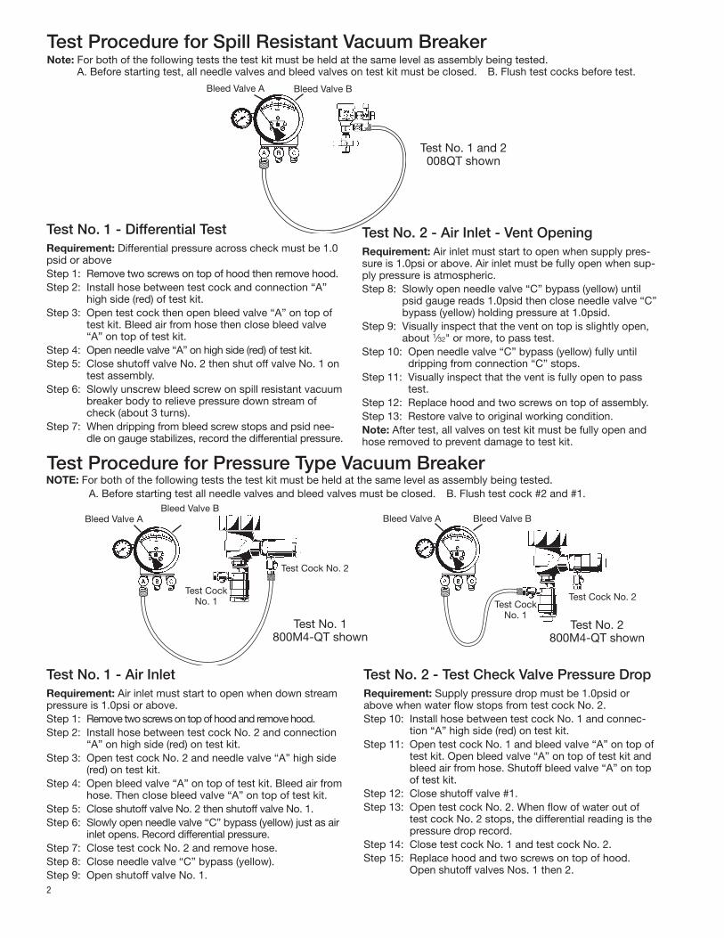
Test Procedure for Spill Resistant Vacuum BreakerNote: For both of the following tests the test kit must be held at the same level as assembly being tested.
A. Before starting test, all needle valves and bleed valves on test kit must be closed. B. Flush test cocks before test.
2
Test No. 1 - Air InletRequirement: Air inlet must start to open when down stream pressure is 1.0psi or above.Step 1: Remove two screws on top of hood and remove hood.Step 2: Install hose between test cock No. 2 and connection
“A” on high side (red) on test kit.Step 3: Open test cock No. 2 and needle valve “A” high side
(red) on test kit. Step 4: Open bleed valve “A” on top of test kit. Bleed air from
hose. Then close bleed valve “A” on top of test kit.Step 5: Close shutoff valve No. 2 then shutoff valve No. 1.Step 6: Slowly open needle valve “C” bypass (yellow) just as air
inlet opens. Record differential pressure.Step 7: Close test cock No. 2 and remove hose. Step 8: Close needle valve “C” bypass (yellow).Step 9: Open shutoff valve No. 1.
Test No. 2 - Test Check Valve Pressure DropRequirement: Supply pressure drop must be 1.0psid or above when water flow stops from test cock No. 2.Step 10: Install hose between test cock No. 1 and connec-
tion “A” high side (red) on test kit.Step 11: Open test cock No. 1 and bleed valve “A” on top of
test kit. Open bleed valve “A” on top of test kit and bleed air from hose. Shutoff bleed valve “A” on top of test kit.
Step 12: Close shutoff valve #1.Step 13: Open test cock No. 2. When flow of water out of
test cock No. 2 stops, the differential reading is the pressure drop record.
Step 14: Close test cock No. 1 and test cock No. 2. Step 15: Replace hood and two screws on top of hood.
Open shutoff valves Nos. 1 then 2.
Test No. 1 - Differential TestRequirement: Differential pressure across check must be 1.0 psid or aboveStep 1: Remove two screws on top of hood then remove hood.Step 2: Install hose between test cock and connection “A”
high side (red) of test kit.Step 3: Open test cock then open bleed valve “A” on top of
test kit. Bleed air from hose then close bleed valve “A” on top of test kit.
Step 4: Open needle valve “A” on high side (red) of test kit.Step 5: Close shutoff valve No. 2 then shut off valve No. 1 on
test assembly.Step 6: Slowly unscrew bleed screw on spill resistant vacuum
breaker body to relieve pressure down stream of check (about 3 turns).
Step 7: When dripping from bleed screw stops and psid nee-dle on gauge stabilizes, record the differential pressure.
NOTE: For both of the following tests the test kit must be held at the same level as assembly being tested. A. Before starting test all needle valves and bleed valves must be closed. B. Flush test cock #2 and #1.
Test Procedure for Pressure Type Vacuum Breaker
Test No. 1 and 2008QT shown
Bleed Valve BBleed Valve A
Bleed Valve BBleed Valve A
Test Cock No. 1
Test Cock No. 2
Bleed Valve BBleed Valve A
Test Cock No. 1
Test Cock No. 2
Test No. 1 800M4-QT shown
Test No. 2 800M4-QT shown
Test No. 2 - Air Inlet - Vent OpeningRequirement: Air inlet must start to open when supply pres-sure is 1.0psi or above. Air inlet must be fully open when sup-ply pressure is atmospheric.Step 8: Slowly open needle valve “C” bypass (yellow) until
psid gauge reads 1.0psid then close needle valve “C” bypass (yellow) holding pressure at 1.0psid.
Step 9: Visually inspect that the vent on top is slightly open, about 1⁄32" or more, to pass test.
Step 10: Open needle valve “C” bypass (yellow) fully until dripping from connection “C” stops.
Step 11: Visually inspect that the vent is fully open to pass test.
Step 12: Replace hood and two screws on top of assembly.Step 13: Restore valve to original working condition.Note: After test, all valves on test kit must be fully open and hose removed to prevent damage to test kit.

3
Test Procedure for Reduced Pressure AssemblyA. All needle valves must be closed on test kit.B. Open test cock No. 4 and flush test cocks Nos. 1, 2 and 3 on reduced pressure assembly then close test cock No. 4.C. Attach hoses as shown. Bleed air from kit, close No. 2 shutoff.
Test No. 4 - Pressure Differential Relief ValvePurpose: To test operation of pressure differential relief valve.Requirements: The pressure differential relief valve must operate to maintain the “zone” between the two check valves at least 2 PSI less than the supply pressure.Step 1: Close needle valve “C” bypass (yellow).Step 2: Open needle valve “A” high side (red).Step 3: Open needle valve “B” low (blue) very slowly until the
differential gauge needle starts to drop.Step 4: Hold the valve at this position and observe the gauge
reading at the moment the first discharge is noted from the relief valve. Record this as the opening differ-ential pressure of the relief valve. Note: it is important that the differential gauge needle drops slowly.
Step 5: Close test cocks Nos. 2 and 3. Remove hose from test cocks Nos. 2 and 3.
Step 6: Use bypass hose (yellow) to relieve pressure from test kit by opening needle valve “A”, “B” and “C” and bleed valves “A” and “B”.
Step 7: Remove all test equipment and open No. 2 shutoff valve of the device.
Test No. 1 - Check Valve No. 2Purpose: To test check valve No. 2 for tightness against reverse flow.Requirements: Valve must be tight against reverse flow under all pressure differentials.Step 1: Slowly open the needle valve “A” high side (red) and
“C” bypass (yellow). Keep the “B” low (blue) closed. Step 2: Open test cock No. 4. Open test cock No. 2 and test
cock No. 3 after opening test cock No. 4.Step 3: Indicated pressure differential will decrease slightly.
If pressure differential continues to decrease (until the vent opens) the No. 2 check valve is reported as “leaking”.
Test No. 2 - Shutoff Valve No. 2Purpose: To test shutoff valve No. 2 for tightness.Step 1: After passing Test No. 1, continue to test No. 2 by
closing test cock No. 2. Step 2: The indicated pressure differential will decrease
slightly. If pressure differential continues to decrease (approaching “zero”) the No. 2 shutoff valve is re-ported to be “leaking”. Note: A leaking No. 2 shutoff will give a false reading in tests No. 3 and 4.
Test No. 3 - To test No. 1 Check ValvePurpose: To test check valve No. 1 for tightness.Requirements: Valve must be tight against reverse flow under all pressure differentials.Step 1: Close needle valve “A” high side (red) and open test
cock No. 2.Step 2: Close test cock No. 4. Disconnect bypass hose (yel-
low) at test cock No. 4. Step 3: Open needle valve “B” low (blue) and “C” bypass
(yellow), bleeding to atmosphere, then closing needle valve “B” (blue) restores the system to a normal static condition.
Step 4: Observe the pressure differential gauge. If there is a decrease in the indicated value, the No. 1 check valve is reported as “leaking”.
Bleed Valve A Bleed Valve B
High (red)
Low (Blue)
Bypass (yellow)
No. 2 Shutoff
909 shown
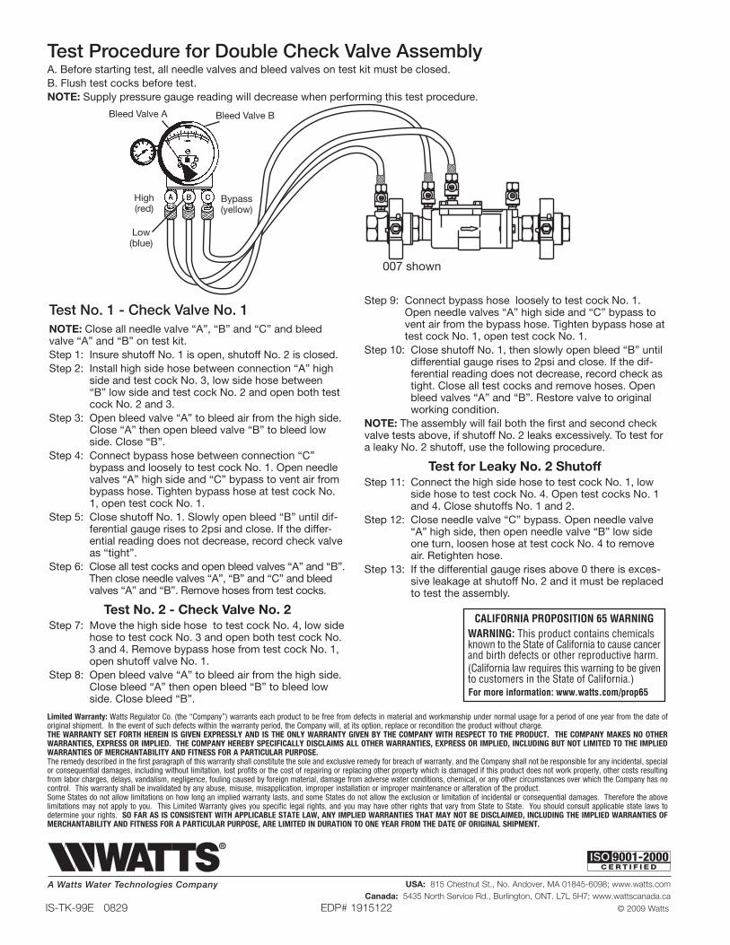
Test Procedure for Double Check Valve AssemblyA. Before starting test, all needle valves and bleed valves on test kit must be closed.B. Flush test cocks before test.NOTE: Supply pressure gauge reading will decrease when performing this test procedure.
Test No. 1 - Check Valve No. 1NOTE: Close all needle valve “A”, “B” and “C” and bleed valve “A” and “B” on test kit.Step 1: Insure shutoff No. 1 is open, shutoff No. 2 is closed.Step 2: Install high side hose between connection “A” high
side and test cock No. 3, low side hose between “B” low side and test cock No. 2 and open both test cock No. 2 and 3.
Step 3: Open bleed valve “A” to bleed air from the high side. Close “A” then open bleed valve “B” to bleed low side. Close “B”.
Step 4: Connect bypass hose between connection “C” bypass and loosely to test cock No. 1. Open needle valves “A” high side and “C” bypass to vent air from bypass hose. Tighten bypass hose at test cock No. 1, open test cock No. 1.
Step 5: Close shutoff No. 1. Slowly open bleed “B” until dif-ferential gauge rises to 2psi and close. If the differ-ential reading does not decrease, record check valve as “tight”.
Step 6: Close all test cocks and open bleed valves “A” and “B”. Then close needle valves “A”, “B” and “C” and bleed valves “A” and “B”. Remove hoses from test cocks.
Test No. 2 - Check Valve No. 2Step 7: Move the high side hose to test cock No. 4, low side
hose to test cock No. 3 and open both test cock No. 3 and 4. Remove bypass hose from test cock No. 1, open shutoff valve No. 1.
Step 8: Open bleed valve “A” to bleed air from the high side. Close bleed “A” then open bleed “B” to bleed low side. Close bleed “B”.
Step 9: Connect bypass hose loosely to test cock No. 1. Open needle valves “A” high side and “C” bypass to vent air from the bypass hose. Tighten bypass hose at test cock No. 1, open test cock No. 1.
Step 10: Close shutoff No. 1, then slowly open bleed “B” until differential gauge rises to 2psi and close. If the dif-ferential reading does not decrease, record check as tight. Close all test cocks and remove hoses. Open bleed valves “A” and “B”. Restore valve to original working condition.
NOTE: The assembly will fail both the first and second check valve tests above, if shutoff No. 2 leaks excessively. To test for a leaky No. 2 shutoff, use the following procedure.
Test for Leaky No. 2 ShutoffStep 11: Connect the high side hose to test cock No. 1, low
side hose to test cock No. 4. Open test cocks No. 1 and 4. Close shutoffs No. 1 and 2.
Step 12: Close needle valve “C” bypass. Open needle valve “A” high side, then open needle valve “B” low side one turn, loosen hose at test cock No. 4 to remove air. Retighten hose.
Step 13: If the differential gauge rises above 0 there is exces-sive leakage at shutoff No. 2 and it must be replaced to test the assembly.
Bleed Valve A Bleed Valve B
High (red)
Low (blue)
Bypass (yellow)
007 shown
IS-TK-99E 0829 EDP# 1915122 © 2009 Watts
Limited Warranty: Watts Regulator Co. (the “Company”) warrants each product to be free from defects in material and workmanship under normal usage for a period of one year from the date of original shipment. In the event of such defects within the warranty period, the Company will, at its option, replace or recondition the product without charge. THE WARRANTY SET FORTH HEREIN IS GIVEN EXPRESSLY AND IS THE ONLY WARRANTY GIVEN BY THE COMPANY WITH RESPECT TO THE PRODUCT. THE COMPANY MAKES NO OTHER WARRANTIES, EXPRESS OR IMPLIED. THE COMPANY HEREBY SPECIFICALLY DISCLAIMS ALL OTHER WARRANTIES, EXPRESS OR IMPLIED, INCLUDING BUT NOT LIMITED TO THE IMPLIED WARRANTIES OF MERCHANTABILITY AND FITNESS FOR A PARTICULAR PURPOSE.The remedy described in the first paragraph of this warranty shall constitute the sole and exclusive remedy for breach of warranty, and the Company shall not be responsible for any incidental, special or consequential damages, including without limitation, lost profits or the cost of repairing or replacing other property which is damaged if this product does not work properly, other costs resulting from labor charges, delays, vandalism, negligence, fouling caused by foreign material, damage from adverse water conditions, chemical, or any other circumstances over which the Company has no control. This warranty shall be invalidated by any abuse, misuse, misapplication, improper installation or improper maintenance or alteration of the product. Some States do not allow limitations on how long an implied warranty lasts, and some States do not allow the exclusion or limitation of incidental or consequential damages. Therefore the above limitations may not apply to you. This Limited Warranty gives you specific legal rights, and you may have other rights that vary from State to State. You should consult applicable state laws to determine your rights. SO FAR AS IS CONSISTENT WITH APPLICABLE STATE LAW, ANY IMPLIED WARRANTIES THAT MAY NOT BE DISCLAIMED, INCLUDING THE IMPLIED WARRANTIES OF MERCHANTABILITY AND FITNESS FOR A PARTICULAR PURPOSE, ARE LIMITED IN DURATION TO ONE YEAR FROM THE DATE OF ORIGINAL SHIPMENT.
USA: 815 Chestnut St., No. Andover, MA 01845-6098; www.watts.comCanada: 5435 North Service Rd., Burlington, ONT. L7L 5H7; www.wattscanada.ca
A Watts Water Technologies Company