wavelength division multiplexing - ryerson universitycourses/ele885/pres10-wdm_devices.pdf ·...
TRANSCRIPT

Wavelength Division MultiplexingConcepts and Components
Xavier FernandoADROIT Group
Ryerson University

Passive Devices• These typically operate completely in the
optical domain (no O/E conversion) and does not need active elements
• Examples: N X N couplers, power splitters, power taps and star couplers
• Technologies:– Fiber based– Optical waveguides based– Micro-optics based

Fig. 10-3: Basic Star Coupler
• Can be wavelength selective/nonselective• Up to N =M = 64, typically N, M < 10 • Typically these have duplex operation
May have N inputs and M outputs

Fig. 10-4: Fused-fiber coupler / Directional coupler
• P3, P4 extremely low ( -70 dB below Po)• Coupling / Splitting Ratio = P2/(P1+P2)• If P1=P2 It is called 3-dB coupler

Definitions
2 1 2Splitting (Coupling) Rat = )i (o P P P+
0 1 2=10 LogExcess Lo [ss ( ] )P P P+
=1In 0 sert Log[ion Loss ] in outP P
3 0= 10 LoCrosstalk g( P P )Try Ex. 10.2

Coupler characteristics
)(sin201 zPP κ=
)(cos202 zPP κ= κ: Coupling Coefficient

The 2 X 2 Waveguide Coupler
• More versatile• Degree of interaction
can be adjusted • Symmetrical or
asymmetrical
P2 = Posin2(kz)e-az
a: Loss Factorκ: Coupling CoefficientZ: Distance

Fig. 10-8: Power distribution Vs guide length

Symmetric & Asymmetric coupler responses

Fig. 10-11: Fused-fiber star coupler
Splitting Loss = -10 Log(1/N) dBExcess Loss = 10 Log (Total Pin/Total Pout)Fused couplers have high excess loss

Fig. 10-12: 8x8 bi-directional star coupler by cascading 3 stages of 3-dB Couplers
c 2Number of 3-dB Cou NN = log N 2
plers (12 = 4 X 3)Try Ex. 10.5
λ1, λ2
λ1, λ2
λ1, λ2 λ3, λ6

InterferometerAn interferometric device uses 2 interfering paths of
different lengths to resolve wavelengthsTypical configuration: 2 3-dB directional couplers
connected with 2 paths having different lengthsApplications:— wideband filters (coarse WDM)separate signals at1300 nm from those at 1550 nm— narrowband filters: filter bandwidth depends on the number of cascades
(i.e. the number of 3-dB couplers connected)

Fig. 10-13: Basic Mach-Zehnder interferometer
Phase shift increases with ∆L, Constructive or destructive interference depending on ∆L
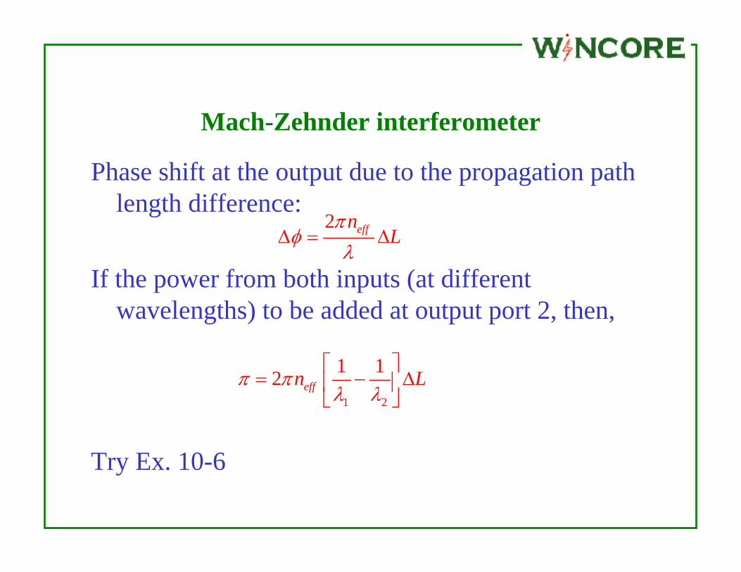
Mach-Zehnder interferometer
Phase shift at the output due to the propagation path length difference:
If the power from both inputs (at different wavelengths) to be added at output port 2, then,
Try Ex. 10-6
1 2
1 12 effn Lπ πλ λ⎡ ⎤
= − ∆⎢ ⎥⎣ ⎦
2 effnL
πφ
λ∆ = ∆

Fig. 10-14: Four-channel wavelength multiplexer

Mach-Zehnder interferometer

Mach-Zehnder interferometer

Mach-Zehnder interferometer
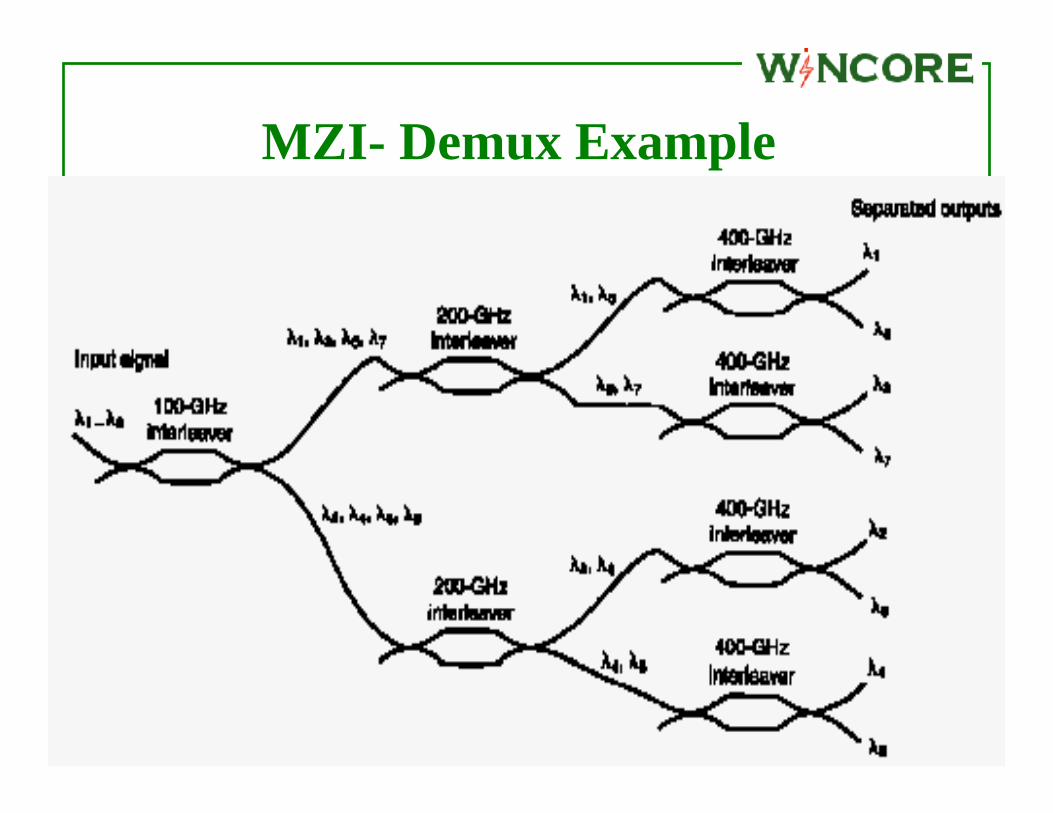
MZI- Demux Example

Fiber Grating Filters• Grating is a periodic structure or
perturbation in a material• Transmitting or Reflecting gratings • The spacing between two adjacent slits is
called the pitch• Grating play an important role in:
– Wavelength filtering– Dispersion compensation– EDFA Gain flattening and many more areas

Reflection grating
Different wavelength can be separated/added

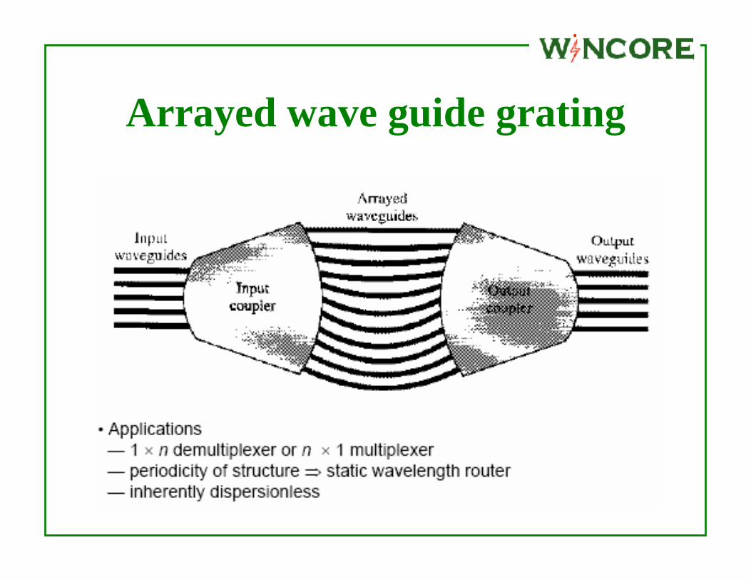
Phase Array Based WDM Devices• The arrayed waveguide is a generalization
of 2X2 MZI multiplexer• The lengths of adjacent waveguides differ
by a constant ∆L• Different wavelengths get multiplexed
(multi-inputs one output) or de-multiplexed (one input multi output)
• For wavelength routing applications multi-input multi-output routers are available

Arrayed wave guide grating
Arrayed wave guide grating

Arrayed wave guide grating
• Wavelength switching example

Multi wavelength sources • Series of discrete DFB lasers
– Straight forward, but expensive stable sources• Wavelength tunable lasers
– By changing the temperature (0.1 nm/OC)– By altering the injection current (0.006 nm/mA)
• Multi-wavelength laser array– Integrated on the same substrate– Multiple quantum wells for better optical and carrier
confinement • Spectral slicing – LED source and comb filters

Fig. 10-20: Tunable DBR Laser

Fig. 10-21: Tunable laser characteristics
Typically, tuning range 10-15 nm,Channel spacing = 10 X Channel width Channel width increases with bit rate

Fig. 10-23: Tunable optical filter

Fig. 10-27: Extended add/drop Mux

Summary• DWDM plays an important role in high
capacity optical networks• Theoretically enormous capacity is possible• Practically wavelength selective (optical signal
processing) components decide it• Passive signal processing elements are
attractive• Optical amplifications is imperative to realize
DWDM networks