wavelength “plan a” – all channels in o-band
TRANSCRIPT

1 09/11/2016 | IEEE 803.2ca Task Force |
Wavelength “Plan A” – All channels in O-Band
Frank Effenberger, Huawei Yong Guo and Xingang Huang, ZTE John Johnson, Broadcom Ltd.
September 11, 2016

2 09/11/2016 | IEEE 803.2ca Task Force |
• Xuguang Chen, Accelink
• Tomoyuki Funada, Sumitomo
• Zhigang Gong, O-net
• Hanhyub Lee, ETRI
• David Li, Hisense-ligent
• Dezhi Zhang, China Telecom
• Jun Zhang, Accelink
• Qisheng Zhao, Hisense-ligent
Supporters

3 09/11/2016 | IEEE 803.2ca Task Force |
• Motivation
• Wavelength “Plan A” proposal
• Optical filter configurations
• Transmission simulation with fiber non-linearities
• Power budgets
• OLT configurations
• Conclusions
Contents

4 09/11/2016 | IEEE 803.2ca Task Force |
• Straw Poll #1: The 802.3ca standard shall specify wavelengths for 25G, 50G, and 100G systems in O-band. – Yes: 15, No: 0, Not enough information: 9
– More information for O-band
– Exact (detailed) wavelength plan including support for coexistence (TDM or WDM)
– Full cost comparison between all O-band and other solutions
– More consensus in presentations
– Dispersion compensation analysis of all solutions
– Full power budget for full 100G system (including mux losses) and what is needed to close the gap
• Straw Poll #2: I prefer: – “1+3” solution: 17, “1+4” solution:3, Need more information: 7
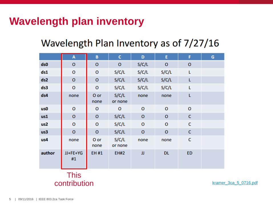
• A majority of task force members thus expressed a preference for a 1+3 wavelength plan in O-band, but there was not sufficient agreement to pass as a motion at the July 2016 meeting.
• An inventory of wavelength plans with “champions” was created to supply the needed information to make a decision (kramer_3ca_5_0716).
Results of July 2016 meeting
5 09/11/2016 | IEEE 803.2ca Task Force |
Wavelength plan inventory
kramer_3ca_5_0716.pdf
This contribution

6 09/11/2016 | IEEE 803.2ca Task Force |
Pros and Cons of fiber transmission bands
O-Band S-Band C-Band L-Band
PR
O
• Lowest fiber dispersion -
no DCM for 20km PMDs*
• Existing cooled 100G-
LR4 lasers and EMLs
• Existing high power
uncooled 25G lasers
• Low fiber insertion loss
• Moderate fiber dispersion
- no DCM for 10km PMDs
• Open fiber spectrum - no
coexistence objectives
• Low fiber insertion loss
• Moderate fiber dispersion
- no DCM for 10km PMDs
• High power booster
EDFAs
• Low-NF preamp EDFAs
• Low fiber insertion loss
• High power booster
EDFAs
• Low-NF preamp EDFAs
CO
N
• High fiber insertion loss
• Limited fiber spectrum –
10G WDM coexistence
and zero dispersion zone
• SOA preamp has high NF
• SOA booster has limited
Psat
• DCM required for 20km
PMDs
• No existing 25G sources
• SOA preamp has high NF
• SOA booster has limited
Psat
• DCM required for 20km
PMDs
• 10G WDM coexistence
prevents use of 1560-
1600nm
• High fiber dispersion -
DCM required for all
PMDs
• Limited fiber spectrum –
10G WDM coexistence
and OTDR band
• Lower laser efficiency
* Assuming NRZ modulation format.

7 09/11/2016 | IEEE 803.2ca Task Force |
• Low dispersion in O-Band allows simple 25G NRZ transmission without need for dispersion compensation. – 25G DML transmission is possible in O- Band (up to ~1320nm) – 25G EML transmission is possible in O+ Band (up to 1360nm)
• 25G O-Band sources and filters exist that can be used directly or adapted for higher power operation for NG-EPON. – Cooled 25G DML/EML TOSAs for 100GBASE-LR4 (~1295-1309nm, 800GHz grid) – Uncooled 25G DML TOSAs for 100G-CWDM4 (1270-1330nm, 20nm grid)
• Spectrum is tight due to need to coexist with 10G-EPON US at 1260-1280nm and avoid the zero dispersion at1302-1324nm to avoid FWM penalties. – Forces use of narrow LAN-WDM channel spacing and narrow US-DS diplexing
filters which is not ideal for low cost due to the need for collimated beams. – Prevents the full adoption of the existing 100GBASE-LR4 grid due to FWM.
• High loss PMDs will require optical amplification. SOAs must be used for amplification in O-Band, but are not as ideal as EDFAs in C/L-Band. – SOA booster amps have more limited output saturation power than EDFAs – SOA pre-amps have considerably higher noise figure than EDFAs
All O-Band wavelength plan considerations
8 09/11/2016 | IEEE 803.2ca Task Force |
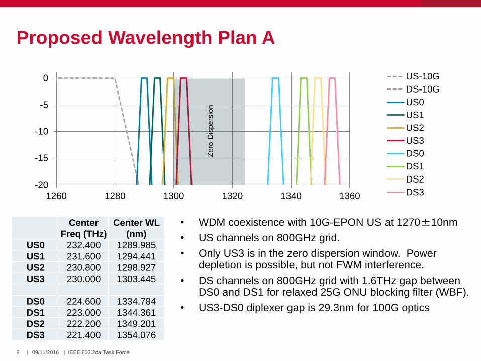
Proposed Wavelength Plan A
Center
Freq (THz)
Center WL
(nm)
US0 232.400 1289.985
US1 231.600 1294.441
US2 230.800 1298.927
US3 230.000 1303.445
DS0 224.600 1334.784
DS1 223.000 1344.361
DS2 222.200 1349.201
DS3 221.400 1354.076
• WDM coexistence with 10G-EPON US at 1270±10nm
• US channels on 800GHz grid.
• Only US3 is in the zero dispersion window. Power depletion is possible, but not FWM interference.
• DS channels on 800GHz grid with 1.6THz gap between DS0 and DS1 for relaxed 25G ONU blocking filter (WBF).
• US3-DS0 diplexer gap is 29.3nm for 100G optics
-20
-15
-10
-5
0
1260 1280 1300 1320 1340 1360
US-10G
DS-10G
US0
US1
US2
US3
DS0
DS1
DS2
DS3
Zero
-Dis
pers
ion

9 09/11/2016 | IEEE 803.2ca Task Force |
ONU filters
Diplexer
• For 25G ONU, DS0-US0 gap = 42.8nm. Use of non-collimated beam is difficult for 45 º diplexer.
• For 100G ONU, DS0-US3 gap = 29.3nm. Collimated beam is needed for 45 º diplexer.
25G Blocking filter
• Wide 1.6THz spacing between DS0 and DS1
• For ±1nm laser tolerance, guardband > 10nm.
• Compatible with low-cost focusing beam optics (liu_3ca_3_0716) for 0 º blocking filter.

10 09/11/2016 | IEEE 803.2ca Task Force |
OLT filters
10/25G Blocking filters
• Blocking filters are needed for WDM coexistence.
• Guardband between 1270± 10nm and US0±1nm is 9nm
• Can use focusing beam optics with longer focal length ROSA at slightly higher cost
10/25G TDM option
• 25G OLT can optionally be configured for TDM coexistence
• Simpler TRISA with one ROSA, no WBF’s
• Requires 10/25G dual-rate burst-mode receiver
Diplexer
• For 25G ONU, DS0-US0 gap = 42.8nm. Use of non-collimated beam is difficult for 45 º diplexer.
• For 100G ONU, DS0-US3 gap = 29.3nm. Collimated beam is needed for 45 º diplexer.

11 09/11/2016 | IEEE 803.2ca Task Force |
Optical network simulated
EML Tx0
EML Tx1
EML Tx2
EML Tx3
APD Rx0
APD Rx1
APD Rx2
APD Rx3
EML Tx0
EML Tx1
EML Tx2
EML Tx3
APD Rx0
APD Rx1
APD Rx2
APD Rx3
10 km
fiber
10 km
fiber 1:32
splitter
Fiber launched power is 8dBm per channel (both directions)
PR-D PR-U
12 09/11/2016 | IEEE 803.2ca Task Force |
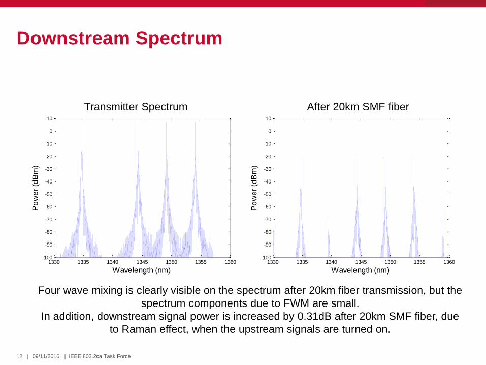
Downstream Spectrum
1330 1335 1340 1345 1350 1355 1360-100
-90
-80
-70
-60
-50
-40
-30
-20
-10
0
10
Wavelength (nm)
Po
we
r (d
Bm
)
Transmitter Spectrum After 20km SMF fiber
Four wave mixing is clearly visible on the spectrum after 20km fiber transmission, but the
spectrum components due to FWM are small.
In addition, downstream signal power is increased by 0.31dB after 20km SMF fiber, due
to Raman effect, when the upstream signals are turned on.
1330 1335 1340 1345 1350 1355 1360-100
-90
-80
-70
-60
-50
-40
-30
-20
-10
0
10
Wavelength (nm)
Po
we
r (d
Bm
)
13 09/11/2016 | IEEE 803.2ca Task Force |
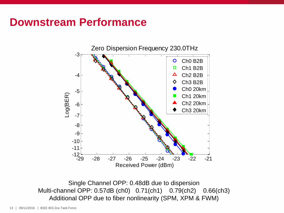
Downstream Performance
Single Channel OPP: 0.48dB due to dispersion
Multi-channel OPP: 0.57dB (ch0) 0.71(ch1) 0.79(ch2) 0.66(ch3)
Additional OPP due to fiber nonlinearity (SPM, XPM & FWM)
-29 -28 -27 -26 -25 -24 -23 -22 -21-12
-11
-10
-9
-8
-7
-6
-5
-4
-3
Received Power (dBm)
Lo
g(B
ER
)
Zero Dispersion Frequency 230.0THz
Ch0 B2B
Ch1 B2B
Ch2 B2B
Ch3 B2B
Ch0 20km
Ch1 20km
Ch2 20km
Ch3 20km
14 09/11/2016 | IEEE 803.2ca Task Force |
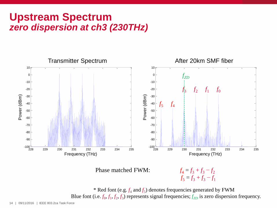
Upstream Spectrum zero dispersion at ch3 (230THz)
228 229 230 231 232 233 234 235-100
-90
-80
-70
-60
-50
-40
-30
-20
-10
0
10
Frequency (THz)
Po
we
r (d
Bm
)
228 229 230 231 232 233 234 235-100
-90
-80
-70
-60
-50
-40
-30
-20
-10
0
10
Frequency (THz)
Po
we
r (d
Bm
)
Transmitter Spectrum After 20km SMF fiber
f4 f5
f0 f1 f2 f3
Phase matched FWM: f4 = f3 + f3 − f2
f5 = f3 + f3 − f1
* Red font (e.g. f4 and f5) denotes frequencies generated by FWM
Blue font (i.e. f0, f1, f2, f3) represents signal frequencies; fZD is zero dispersion frequency.
fZD
15 09/11/2016 | IEEE 803.2ca Task Force |
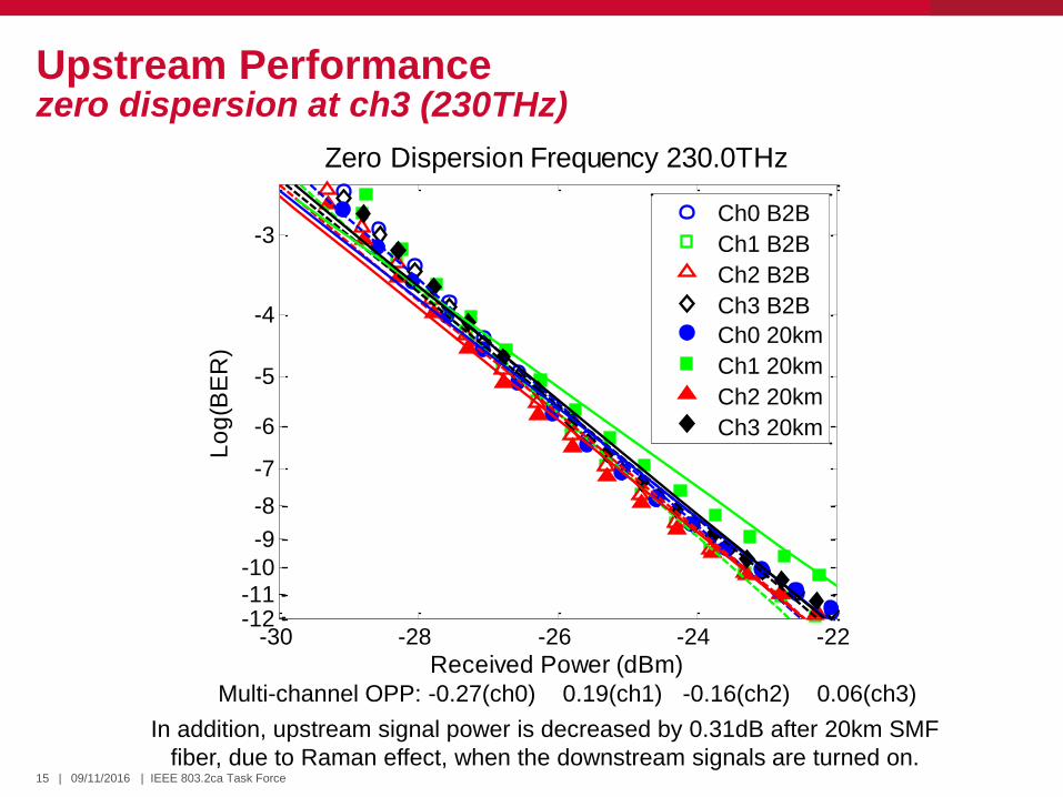
Upstream Performance zero dispersion at ch3 (230THz)
Multi-channel OPP: -0.27(ch0) 0.19(ch1) -0.16(ch2) 0.06(ch3)
-30 -28 -26 -24 -22-12-11-10
-9
-8
-7
-6
-5
-4
-3
Received Power (dBm)
Lo
g(B
ER
)
Zero Dispersion Frequency 230.0THz
Ch0 B2B
Ch1 B2B
Ch2 B2B
Ch3 B2B
Ch0 20km
Ch1 20km
Ch2 20km
Ch3 20km
In addition, upstream signal power is decreased by 0.31dB after 20km SMF
fiber, due to Raman effect, when the downstream signals are turned on.

16 09/11/2016 | IEEE 803.2ca Task Force |
Upstream Spectrum zero dispersion in the middle of Ch3 (230.0THz) and Ch2 (230.8THz)
228 229 230 231 232 233 234 235-100
-90
-80
-70
-60
-50
-40
-30
-20
-10
0
10
Frequency (THz)
Po
we
r (d
Bm
)
228 229 230 231 232 233 234 235-100
-90
-80
-70
-60
-50
-40
-30
-20
-10
0
10
Frequency (THz)
Po
we
r (d
Bm
)
Transmitter Spectrum After 20km SMF fiber
Phase matched FWM: f4 = f2 + f3 − f1
f5 = f2 + f3 − f0
fZD
f0 f1 f2 f3
f4 f5

17 09/11/2016 | IEEE 803.2ca Task Force |
Upstream Performance zero dispersion in the middle of Ch3 (230.0THz) and Ch2 (230.8THz)
Multi-channel OPP: -0.32(ch0) 0.14(ch1) -0.05(ch2) 0.06(ch4)
-30 -28 -26 -24 -22-12-11-10
-9
-8
-7
-6
-5
-4
-3
Received Power (dBm)
Lo
g(B
ER
)Zero Dispersion Frequency 230.4THz
Ch0 B2B
Ch1 B2B
Ch2 B2B
Ch3 B2B
Ch0 20km
Ch1 20km
Ch2 20km
Ch3 20km

18 09/11/2016 | IEEE 803.2ca Task Force |
Upstream Spectrum zero dispersion at ch2 (230.8THz) (Note: this cannot happen in G.652 fiber)
228 229 230 231 232 233 234 235-100
-90
-80
-70
-60
-50
-40
-30
-20
-10
0
10
Frequency (THz)
Po
we
r (d
Bm
)
228 229 230 231 232 233 234 235-100
-90
-80
-70
-60
-50
-40
-30
-20
-10
0
10
Frequency (THz)
Po
we
r (d
Bm
)
Transmitter Spectrum After 20km SMF fiber
fZD
f4
Phase matched FWM: f1 = f2 + f2 − f3
f2 = f3 + f1 − f2
f3 = f2 + f2 − f1
f4 = f2 + f2 − f0
f4 = f3 + f1 − f0
f0 f1 f2 f3
f1 f2 f3

19 09/11/2016 | IEEE 803.2ca Task Force |
Upstream Spectrum zero dispersion at Ch2 (230.8THz)
-30 -28 -26 -24 -22 -20-12-11-10-9-8
-7
-6
-5
-4
-3
-2
Received Power (dBm)
Lo
g(B
ER
)
Zero Dispersion Frequency 230.8THz
-30 -28 -26 -24 -22 -20-12-11-10-9-8
-7
-6
-5
-4
-3
-2
Received Power (dBm)
Lo
g(B
ER
)
Zero Dispersion Frequency 231.2THz
Ch0 B2B
Ch1 B2B
Ch2 B2B
Ch3 B2B
Ch0 20km
Ch1 20km
Ch2 20km
Ch3 20km
While this result is not possible for NG-EPON Plan A, it shows why the existing 100GBASE-LR4 grid cannot be used.

20 09/11/2016 | IEEE 803.2ca Task Force |
• Use vendor TX data of harstead_3ca_1a_0716 at mean + 1*sigma level as a view of future laser capability – Vendors were asked to estimate commercial values for output power in a single-
channel BOSA configuration including diplexer loss and manufacturing margin. – US channels will use cooled DML with ER = 6dB
– 25G BOSA average output power = 8.2 dBm – 100G mux loss = 2.5dB
– DS channels will use cooled EML with ER = 8dB – 25G BOSA average output power = 5.3dBm – 100G mux loss = 2.5dB
• Assume 25G APD has typical AOP sensitivity equal to -28dBm at BER=10-3 in a ROSA package (without diplexer or blocking filter) with TX ER=9dB – Value to be refined as more data becomes available – this is a starting point – Combined diplexer, 100G TFF demux and blocking filter loss = 3dB – ER penalty is 0.3dB for ONU RX and 1.1dB for OLT RX – Assume 1dB excess APD noise penalty for DML with low ER. This is highly
dependent on the ratio of APD and TIA noise. Need more data. – Note tanaka_3ca_1_0716 showed 2dB OMA penalty between DML ER = 7dB and
EML ER=10dB. Some of this could be due to difference between DML and EML eye quality.
Estimated component capabilities

21 09/11/2016 | IEEE 803.2ca Task Force |
• The following budgets use the following design method
– Defined interface is to the ODN, meaning mux losses included in the optics
• Downstream PR20, 30, and40
– Start with achievable ONU stressed sensitivity (common across classes)
– OLT Tx Min = ONU Str. Sen + Max Link loss
– OLT Tx Max = OLT Tx min + reasonable tolerance
– ONU Rx Overload = OLT Tx max – Min Link loss
• Upstream PR20, 30, and 40
– Start with achievable ONU Tx Min power (common across classes)
– ONU Tx Max = ONU Tx Min + reasonable tolerance
– OLT Rx Str. Sen.= ONU Tx Min – Max Link loss
– OLT Rx Overload = ONU Tx Max – Min Link loss
• PR10 class: Begin with PR20 then degrade ONU Tx and Rx
Power budget design style

22 09/11/2016 | IEEE 803.2ca Task Force |
• The levels used in this budget are meant to be first level approximations – They are used to illustrate the basic configuration of the plan
– To justify the nonlinear analysis previously stated
• The levels need to be optimized on several bases – Technical feasibility
– Economic feasibility
– Reliability, power consumption, environment
• Once a plan is selected, these optimizations can be finalized
Disclaimer: This budget is a strawman only
23 09/11/2016 | IEEE 803.2ca Task Force |
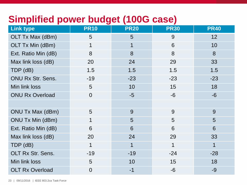
Simplified power budget (100G case) Link type PR10 PR20 PR30 PR40
OLT Tx Max (dBm) 5 5 9 12
OLT Tx Min (dBm) 1 1 6 10
Ext. Ratio Min (dB) 8 8 8 8
Max link loss (dB) 20 24 29 33
TDP (dB) 1.5 1.5 1.5 1.5
ONU Rx Str. Sens. -19 -23 -23 -23
Min link loss 5 10 15 18
ONU Rx Overload 0 -5 -6 -6
ONU Tx Max (dBm) 5 9 9 9
ONU Tx Min (dBm) 1 5 5 5
Ext. Ratio Min (dB) 6 6 6 6
Max link loss (dB) 20 24 29 33
TDP (dB) 1 1 1 1
OLT Rx Str. Sens. -19 -19 -24 -28
Min link loss 5 10 15 18
OLT Rx Overload 0 -1 -6 -9

24 09/11/2016 | IEEE 803.2ca Task Force |
25G OLT configurations
• Three possible 25G OLT configurations depending on deployment scenario – Separate 10/10G and 25/25G OLTs with simple
BOSA optics and external diplexer (no support for 25/10G ONUs)
– Combined 10/25G OLT with Quad OSA optics (more complex optics, supports 25/10G ONUs)
– Combined 10/25G OLT with TRISA optics with dual-rate RX for TDM coexistence (simpler optics, but more complex TIA).
• TDM coexistence has the advantage of support for 25/10G ONUs and simplifier TRISA optics without WBFs – Can’t afford a sensitivity penalty for dual-rate TIA
10G 1577 TX
25G 1335 TX
10G 1270 RX
25G 1290 RX
10/2
5G
OLT
WDM Coexisting 25/10G Quad OSA
10G 1577 TX
25G 1335 TX
10G 1270 RX
25G 1290 RX
10G
O
LT
25G
O
LT
Separate 10/10G and 25/25G OLT BOSAs
No support
for 25/10G ONUs
10G 1577 TX
25G 1335 TX
10/25G DR RX 10/2
5G
OLT
TDM Coexisting 25/10G TRISA

25 09/11/2016 | IEEE 803.2ca Task Force |
10/100G OLT with optional SOA’s for PR40
25G DS0 TX
25G DS1 TX
25G DS2 TX
25G DS3 TX
10/1
00G
OLT
10G 1577 TX
10G 1270 RX
mu
x
25G US0 RX
25G US1 RX
25G US2 RX
25G US3 RX
dem
ux
OA
• 10G TX/RX may be difficult to integrate in same module as 100G TX/RX due to limits on pins, power and space.
• Need for OA option for 100G OLT favors duplex optical modules with external diplexers/combiners.
OA
Booster SOA module
SOA preamp module
TP2/TP7
100G transceiver – QSFP28/CFP4
10G transceiver – XFP
Optional
Optional
1577
1335-1354
1290-1304
1577
1270
1270

26 09/11/2016 | IEEE 803.2ca Task Force |
• Keeping all channels in O-band has two main advantages: – Low dispersion in O-Band allows simple 25G NRZ transmission without
need for dispersion compensation and the cost and loss that comes with it.
– 25G DML and EML sources and filters exist that can be used directly or adapted for higher power operation for NG-EPON.
• The main disadvantage is the limited available spectrum due to 10G-EPON coexistence and the dispersion zero window – Forces use of LAN-WDM channel spacing (800GHz), but this is common
in several other wavelength plans as well. – Forces narrow US-DS guardband which is more difficult to implement
without collimated beam optics which add cost.
– Prevents the full adoption of the existing 100GBASE-LR4 grid due to FWM penalties in the zero dispersion window.
• High loss PMDs will require optical amplification in all wavelength plans. SOAs must be used for amplification in O-Band. – SOAs are not as ideal amplifiers as EDFAs in C/L-band but are smaller,
lower cost and lower power consumption.
Conclusions

27 09/11/2016 | IEEE 803.2ca Task Force |
Thank You!