wb service manual rev 1edits 2 - daparak · arrow and the pump model and serial numbers. the model...
TRANSCRIPT


TABLE OF CONTENTS
PAGE 1-1. INTRODUCTION ................................................................................................................................................. 1
1-2. General.................................................................................................................................................. 1 1-3. Scope .................................................................................................................................................... 1 1-4. Nameplate Data..................................................................................................................................... 1 1-5. Pump Rotation....................................................................................................................................... 1 1-6. Model Number ....................................................................................................................................... 1
2-1. INSTALLATION ................................................................................................................................................... 2 2-2. General.................................................................................................................................................. 2 2-3. Piping..................................................................................................................................................... 2 2-4. Foundation............................................................................................................................................. 2
3-1. OPERATION ...................................................................................................................................................... 2 3-2. Initial Check ........................................................................................................................................... 2 3-3. Start-up.................................................................................................................................................. 2 3-4. Packing Leakage ................................................................................................................................... 2
4-1. MAINTENANCE................................................................................................................................................... 2 4-2. General.................................................................................................................................................. 2 4-3. Packing Adjustment ............................................................................................................................... 2 4-4. Packing Replacement............................................................................................................................ 3
5-1. DISASSEMBLY.................................................................................................................................................... 3 5-2. Disconnect Pump................................................................................................................................... 3 5-3. Stator Removal ...................................................................................................................................... 3 5-4. Suction Housing Removal ..................................................................................................................... 3 5-5. Rotor/Con Rod/Drive Shaft Assembly Removal .................................................................................... 3 5-6. Packing Housing Removal...................................................................................................................... 4 5-7. Seal Housing Removal ........................................................................................................................... 4 5-8. Rotor, Driveshaft, and Connecting Rod Disassembly ............................................................................. 4 5-9. Drive Adapter/Gearmotor Removal........................................................................................................ 4 5-10. Cleaning ............................................................................................................................................... 4
6-1. INSPECTION........................................................................................................................................................ 4 6-2. Drive Shaft and Packing/Seals .............................................................................................................. 4 6-3. Rotor...................................................................................................................................................... 4 6-4. Stator ..................................................................................................................................................... 5 6-5. All Other Parts ....................................................................................................................................... 5
7-1. ASSEMBLY.......................................................................................................................................................... 5 7-2. Lubrication During Assembly ................................................................................................................. 5 7-3. Driveshaft and Rotor Gear Joint Assembly............................................................................................ 5 7-4. Drive Adapter Assembly ........................................................................................................................ 6 7-5. Pumps with Single Mechanical Seal ...................................................................................................... 6 7-6. Pumps with Compression Packing ........................................................................................................ 6 7-7. Pumps with Double or Cartridge Mechanical Seals ............................................................................... 6 7-8. Rotor/Stator Assembly........................................................................................................................... 6 7-9. Pump Connections.............................................................................................................................................. 6
8-1. STORAGE ........................................................................................................................................................... 7 9-1. RECOMMENDED SPARE PARTS ...................................................................................................................... 7 10-1. HARDWARE LIST ............................................................................................................................................. 8 11-1. PARTS LIST ..................................................................................................................................................... 9
12-1. EXPLODED VIEW ........................................................................................................................................... 10 13-1. SEAL SET DIMENSIONS ................................................................................................................................ 11 14-1 TROUBLESHOOTING CHART........................................................................................................................ 12
1
SERVICE MANUAL
Moyno 2000 WB Pumps
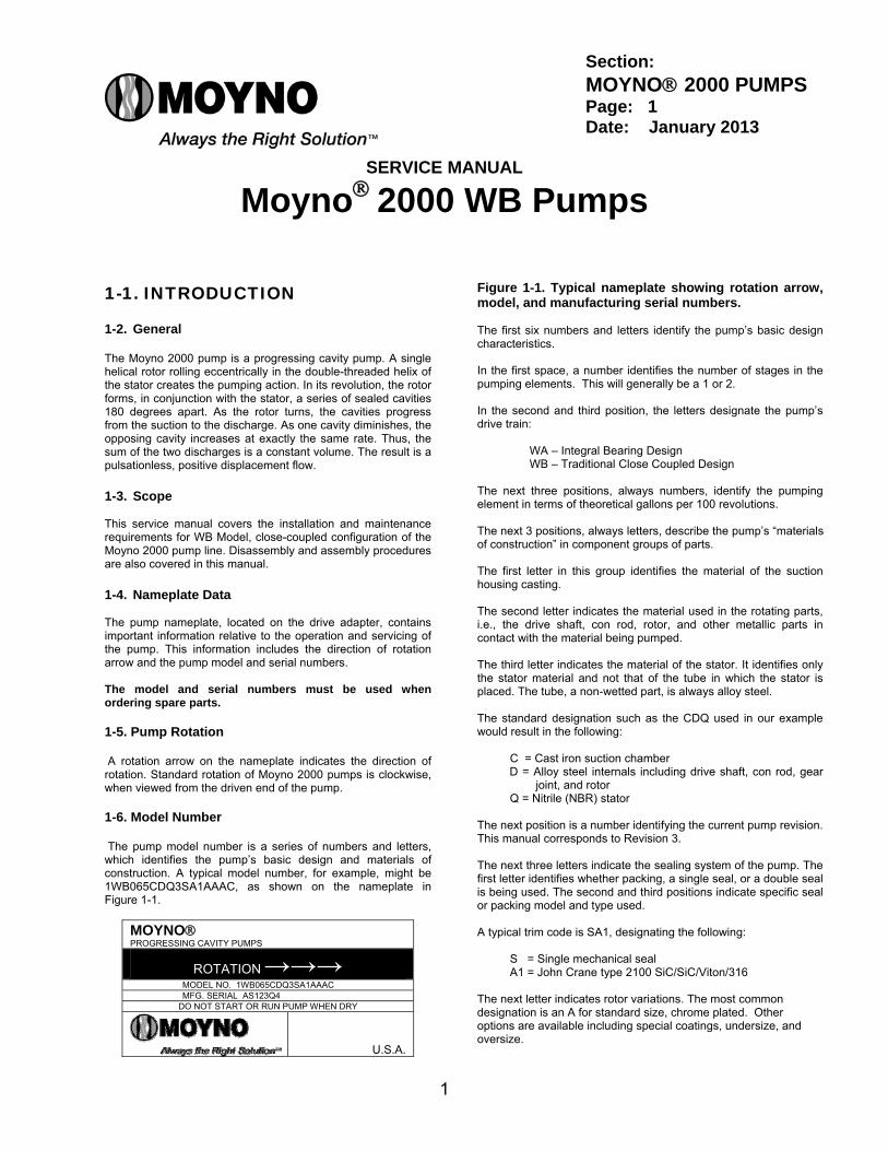
1-1. INTRODUCTION 1-2. General The Moyno 2000 pump is a progressing cavity pump. A single helical rotor rolling eccentrically in the double-threaded helix of the stator creates the pumping action. In its revolution, the rotor forms, in conjunction with the stator, a series of sealed cavities 180 degrees apart. As the rotor turns, the cavities progress from the suction to the discharge. As one cavity diminishes, the opposing cavity increases at exactly the same rate. Thus, the sum of the two discharges is a constant volume. The result is a pulsationless, positive displacement flow. 1-3. Scope This service manual covers the installation and maintenance requirements for WB Model, close-coupled configuration of the Moyno 2000 pump line. Disassembly and assembly procedures are also covered in this manual. 1-4. Nameplate Data The pump nameplate, located on the drive adapter, contains important information relative to the operation and servicing of the pump. This information includes the direction of rotation arrow and the pump model and serial numbers. The model and serial numbers must be used when ordering spare parts. 1-5. Pump Rotation A rotation arrow on the nameplate indicates the direction of rotation. Standard rotation of Moyno 2000 pumps is clockwise, when viewed from the driven end of the pump. 1-6. Model Number The pump model number is a series of numbers and letters, which identifies the pump’s basic design and materials of construction. A typical model number, for example, might be 1WB065CDQ3SA1AAAC, as shown on the nameplate in Figure 1-1.
MOYNO PROGRESSING CAVITY PUMPS
ROTATION →→→ MODEL NO. 1WB065CDQ3SA1AAAC MFG. SERIAL AS123Q4
DO NOT START OR RUN PUMP WHEN DRY
U.S.A.
Figure 1-1. Typical nameplate showing rotation arrow, model, and manufacturing serial numbers. The first six numbers and letters identify the pump’s basic design characteristics. In the first space, a number identifies the number of stages in the pumping elements. This will generally be a 1 or 2. In the second and third position, the letters designate the pump’s drive train:
WA – Integral Bearing Design WB – Traditional Close Coupled Design
The next three positions, always numbers, identify the pumping element in terms of theoretical gallons per 100 revolutions. The next 3 positions, always letters, describe the pump’s “materials of construction” in component groups of parts. The first letter in this group identifies the material of the suction housing casting. The second letter indicates the material used in the rotating parts, i.e., the drive shaft, con rod, rotor, and other metallic parts in contact with the material being pumped. The third letter indicates the material of the stator. It identifies only the stator material and not that of the tube in which the stator is placed. The tube, a non-wetted part, is always alloy steel. The standard designation such as the CDQ used in our example would result in the following:
C = Cast iron suction chamber D = Alloy steel internals including drive shaft, con rod, gear
joint, and rotor Q = Nitrile (NBR) stator
The next position is a number identifying the current pump revision. This manual corresponds to Revision 3. The next three letters indicate the sealing system of the pump. The first letter identifies whether packing, a single seal, or a double seal is being used. The second and third positions indicate specific seal or packing model and type used. A typical trim code is SA1, designating the following:
S = Single mechanical seal A1 = John Crane type 2100 SiC/SiC/Viton/316
The next letter indicates rotor variations. The most common designation is an A for standard size, chrome plated. Other options are available including special coatings, undersize, and oversize.
Section: MOYNO 2000 PUMPS Page: 1 Date: January 2013
2
The next letter indicates whether there are any special options being used in the pump; typically this is an A for no special options. The next letter indicates the suction configuration. For this pump an A is used designating a standard flanged pump. The last letter indicates the drive configuration and flange/shaft/seal size. In our close coupled pump nameplate the C designates a 250mm flange and 45mm shaft.
2-1. INSTALLATION 2-2. General Accessibility to the pump and adequate clearance should be prime considerations in any installation. Enough space should surround the unit so that maintenance can be performed with ease. 2-3. Piping 1. Suction piping should be as short as possible. Normally,
the suction line should be the same diameter as the pump suction; however, conditions such as high viscosity or required minimum flow velocities may dictate otherwise. Long-sweep 90-degree elbows or 45-degree elbows should be used instead of the standard elbow. Avoid using suction piping loops, which trap air.
2. Discharge piping diameter should generally be as large as
the discharge port unless fluid conditions indicate otherwise.
3. An easily removable section of piping, at least twice as
long as the stator, should be mated to the discharge port. This will allow the rotor and stator to be removed without having to remove the complete pump from the base.
2-4. Foundation For maximum pump-driver unit life, each unit should be mounted on a strong steel baseplate. The baseplate should be mounted on a firm foundation. The motors should be supported on close-coupled configurations above 30 HP.
3-1. OPERATION 3-2. Initial Check Before putting the pump into operation, the following items should be checked to ensure that each piece of equipment is installed correctly: Electrical connections. Gauges and other instruments. Pump rotation. Rotation is indicated on the pump
nameplate. All valves should be open on both suction and discharge
sides of pump. Seal flush systems if required should be operational.
Double seals require flushing between faces. CAUTION: This is a positive displacement pump. Do not
operate it against a closed valve.
3-3. Start-Up CAUTION: DRY OPERATION IS HARMFUL TO THE PUMP! Never allow the pump to operate without liquid, as dry operation will cause premature wear of the stator and possible damage. The liquid being pumped lubricates the stator.
1. Before operating the pump for the first time, fill it with liquid to lubricate the stator for the initial start-up.
Note: If the pump is shut down temporarily, enough liquid will
remain in the system to provide lubrication upon restarting. It is advisable to maintain the suction piping at a higher elevation than the centerline of the pump in order to contain some liquid in the pump at time of shutdown.
2. Once the pump has been filled with liquid, check for direction
of pump rotation by momentarily starting and stopping the drive. See pump nameplate for correct rotation.
3. Start seal flush water if so equipped.
4. Start pump.
3-4. Packing Leakage The packed stuffing box is designed to control leakage, not stop it completely. Leakage is necessary to reduce friction and dissipate heat. In a new pump, before the packing has had a chance to seat properly, excessive leakage through the stuffing box is common. Frequent adjustments of the packing gland may be necessary during the first few hours of operation in order to compress and seat the packing. See Section 4-3.
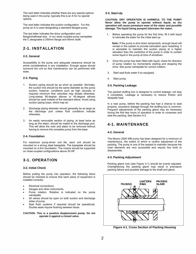
4-1. MAINTENANCE 4-2. General The Moyno 2000 WB pump has been designed for a minimum of maintenance, the extent of which is routine adjustment of the packing. The pump is one of the easiest to maintain because the main elements are very accessible and require few tools to disassemble. 4-3. Packing Adjustment Packing gland nuts (see Figure 4-1) should be evenly adjusted. Overtightening the packing gland may result in premature packing failure and possible damage to the shaft and gland.
Figure 4-1. Cross Section of Packing Housing
3
When packing is new, frequent minor adjustments during the first few hours of operation are recommended in order to compress and seat the packing.
1. Upon initial start-up of the pump, adjust the gland nuts for a leakage rate of 50-11 drops per minute until the packing has seated and adjusted to the operating temperature (approximately 10-15 minutes).
2. If leakage is excessive after 15 minutes of operation,
tighten the gland nuts ¼ of a turn.
3. Tighten the gland nuts ¼ of a turn after an additional 15 minutes if necessary and repeat this procedure until a desired leakage of 1-2 drops per minute is obtained. Adding grease may also reduce leakage by providing a barrier at the lantern ring.
CAUTION: Do not tighten until zero leakage is obtained. Overtightening the packing gland may result in accelerated wear on the packing and damage to the shaft. In those situations where no packing leakage can be tolerated, consult your Moyno Authorized Representative.
Area To Lubricate Approved Lubricant or
Equivalent
Packing ACG-2
(Dubois Chemical, Inc.) 4-4. Packing Replacement Note: In this section, the first reference to each pump part will be followed by a number or a letter in parentheses ( ). These numbers and letters are used to identify the pump parts and hardware items in the Exploded Views in Section 13-1. When tightening the gland nuts can no longer regulate leakage, remove and replace the packing. The entire pump does not need to be disassembled to replace the packing. Briefly, replace as follows: 1. Remove packing gland nuts and slide gland halves (36)
back along drive shaft (26).
2. Use a packing puller tool (see Figure 4-2) to remove the packing (34).
Figure 4-2. Packing Removal Tool
3. Inspect surface of drive shaft for excessive wear or
grooves due to packing rub. If shaft is worn, or is badly scored or grooved, it should be replaced.
4. If drive shaft is not worn, install a lantern ring and four
packing rings, lubricating them before installation with a good grade of packing grease. Be sure to stagger the packing ring joints at 90-degree increments.
sd Note: The stuffing box is supplied with four rings installed, a
fifth ring may be added after initial compression. CAUTION: ALWAYS USE A PROPER PACKING TAMPER TOOL TO INSTALL PACKING. Do not use a pointed or sharp tool, as damage to the packing material or drive shaft could result. To assure proper shaft lubrication, never use a one-piece spiral wrap packing. 5. Replace packing gland halves and secure with packing
gland and nuts (T).
6. Adjust packing per Section 4-3.
5-1. DISASSEMBLY
Note: In this section and in following sections on CLEANING, INSPECTION, and ASSEMBLY, the first reference to each pump part will be followed by a number or letter in parentheses ( ). These numbers and letters are those used to identify the pump parts and hardware items in the Exploded Views in Section 13-1.
5-2. Disconnect Pump 1. Disconnect the power source. 2. Close suction and discharge valves to isolate the pump from
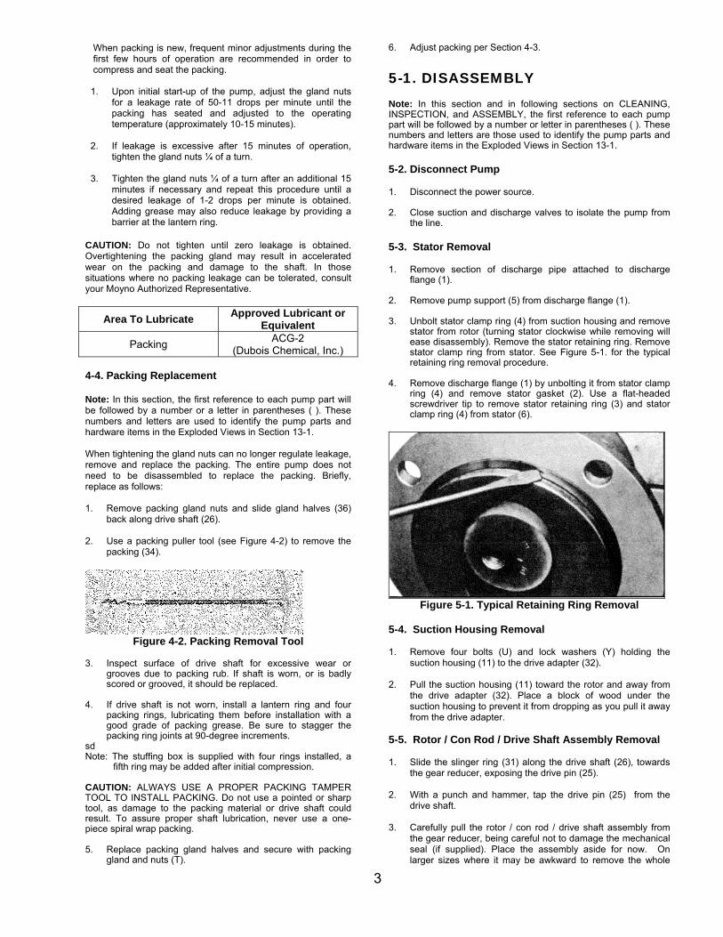
the line. 5-3. Stator Removal 1. Remove section of discharge pipe attached to discharge
flange (1). 2. Remove pump support (5) from discharge flange (1). 3. Unbolt stator clamp ring (4) from suction housing and remove
stator from rotor (turning stator clockwise while removing will ease disassembly). Remove the stator retaining ring. Remove stator clamp ring from stator. See Figure 5-1. for the typical retaining ring removal procedure.
4. Remove discharge flange (1) by unbolting it from stator clamp
ring (4) and remove stator gasket (2). Use a flat-headed screwdriver tip to remove stator retaining ring (3) and stator clamp ring (4) from stator (6).
Figure 5-1. Typical Retaining Ring Removal
5-4. Suction Housing Removal 1. Remove four bolts (U) and lock washers (Y) holding the
suction housing (11) to the drive adapter (32). 2. Pull the suction housing (11) toward the rotor and away from
the drive adapter (32). Place a block of wood under the suction housing to prevent it from dropping as you pull it away from the drive adapter.
5-5. Rotor / Con Rod / Drive Shaft Assembly Removal 1. Slide the slinger ring (31) along the drive shaft (26), towards
the gear reducer, exposing the drive pin (25). 2. With a punch and hammer, tap the drive pin (25) from the
drive shaft. 3. Carefully pull the rotor / con rod / drive shaft assembly from
the gear reducer, being careful not to damage the mechanical seal (if supplied). Place the assembly aside for now. On larger sizes where it may be awkward to remove the whole
4
rotating unit as one piece, the rotor can be removed first. Refer to section 5-8 for joint disassembly instructions.
5-6. Packing Housing Removal 1. Pull the packing housing (33) away from the drive adapter
(32). Remove the O-ring (29). 2. Remove the gland nuts (T), studs (S), and packing gland
halves (36). 3. Use a packing removal tool to remove two rings of
packing (34), two lantern rings (35), and the last two rings of packing (34).
OR
5-7. Seal Housing Removal 1. Pull the seal housing (30) from the drive adapter (32).
Remove the O-ring (29). 2. Carefully push the stationary seal face from the seal
housing (30).. 3. Carefully pull the rotating portion of the mechanical seal
(28) from the drive shaft (26). 5-8. Rotor, Driveshaft, and Connecting Rod Disassembly 1. Remove the vent plug (P) and set screw (Q) from the gear
joint shell (23). 2. Remove six socket head screws (O) and hi-collar lock
washers (L) from head ring (12). 3. Remove head ring (12) and O-ring (15). 4. Slide connecting rod/gear joint assembly off the rotor
head. 5. Remove gear joint keys (14) and primary thrust plate (16)
from rotor (13). 6. Slide gear joint shell (23) off gear ball/connecting rod
assembly. 7. Slide ring gear (17) off gear ball (19). 8. Secure connecting rod (24) so that it will not be able to
turn and remove lock nut (18). 9. Remove gear ball (19), secondary thrust plate (20), seal
support (21), and gear joint seal (22) from connecting rod. 10. Repeat steps 2 through 9 for driveshaft joint disassembly.
NOTE: It is recommended that each time the rotor and gear joint is disassembled, the rotor head O-ring (14) and gear joint seal (22) should be replaced. 5-9. Drive Adapter / Gearmotor Removal Remove the four hex head bolts (X), lock washers (V), and hex nuts (W) holding the drive adapter (32) to the gear reducer. Pull the gear motor from the drive adapter (32). 5-10. Cleaning Clean parts in a suitable cleaning solvent.
6-1. INSPECTION 6-2. Drive shaft and Packing/Seals 1. Inspect drive shaft (26) for scoring, burrs, cracks, etc. Replace
as necessary. 2. It is recommended to always replace O-rings and gear joint
seals. 3. It is recommended to replace mechanical seals when the pump
is disassembled. Extreme care should be taken to protect the seal faces from damage. These are fragile; avoid touching the faces and keep them clean.
The rubber bellows will adhere to the shaft after assembly and must be replaced if removed from the shaft.
4. It is recommended to always replace packing (34) whenever
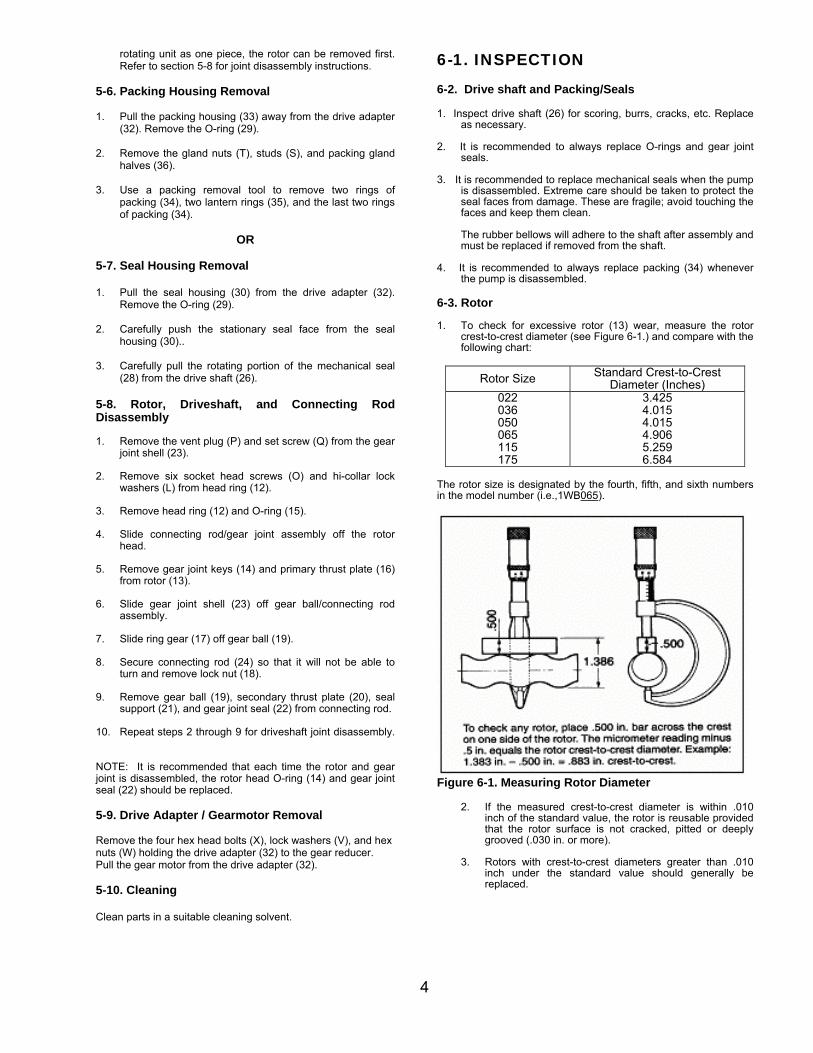
the pump is disassembled. 6-3. Rotor 1. To check for excessive rotor (13) wear, measure the rotor
crest-to-crest diameter (see Figure 6-1.) and compare with the following chart:
Rotor Size Standard Crest-to-Crest Diameter (Inches)
022 036 050 065 115 175
3.425 4.015 4.015 4.906 5.259 6.584
The rotor size is designated by the fourth, fifth, and sixth numbers in the model number (i.e.,1WB065).
Figure 6-1. Measuring Rotor Diameter
2. If the measured crest-to-crest diameter is within .010 inch of the standard value, the rotor is reusable provided that the rotor surface is not cracked, pitted or deeply grooved (.030 in. or more).
3. Rotors with crest-to-crest diameters greater than .010
inch under the standard value should generally be replaced.
5
6-4. Stator The best indication of stator (6) wear and the need for replacement is a drop in pump performance. Stators with interior surfaces that are pitted, grooved or gouged should also be replaced. 6-5. All Other Parts Check for cracks, excessive wear, damage to threaded holes, burrs, etc. Replace as necessary. Replace O-rings (29) and both stator gaskets (2) after each time the pump is disassembled.
7-1. ASSEMBLY 7-2. Lubrication During Assembly 1. Gear Joints. Both gear joints should be packed with
lubricant during assembly (Section 7-3). DO NOT use zerk fittings to lubricate gear joints after assembly. The pipe plugs (P) in the gear joint shells (23) are vent plugs and MUST BE REMOVED during assembly of the gear joints to allow excess lubricant to vent from the gear joints.
2. Packing. Lubricate packing rings during assembly.
Additional grease can be added after assembly through zerk fittings if installed in the side of the stuffing box.
3. Approved Lubricants: CAUTION: Do not mix different brands of lubricants for the same application.
Area to Lubricate Approved Lubricant or Equivalent
Packing ACG-2 (Dubois Chemical, Inc.)
Area to Lubricate Approved Lubricant Gear Joints Mobil 1 Grease
(Manufactured by Exxon-Mobil of Irving, Texas)
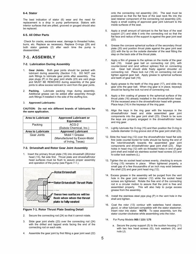
7-3. Driveshaft and Rotor Gear Joint Assembly 1. Insert the primary thrust plate (16) into driveshaft (26)/rotor
head (13), flat side first. Thrust plate and driveshaft/rotor head surfaces must be flush to assure proper assembly and operation of the pump (see Figure 7-1.).
Figure 7-1. Rotor Thrust Plate Seating Detail 2. Secure the connecting rod (24) so that it cannot rotate. 3. Slide gear joint shells (23) over the connecting rod (24)
with the drilled and tapped ends facing the end of the connecting rod on each side.
4. Assemble the gear joint by first fitting a gear joint seal (22)
onto the connecting rod assembly (24). The seal must be positioned so that the flat face of the seal neck fits into the seal retainer component of the connecting rod assembly (24). Apply a small coating of approved gear joint lubricant to the inside surfaces of the seal.
5. Apply a small amount of lubricant to the flat face of the seal
support (21) and slide it onto the connecting rod so that the flat face and radius of the support is against the gear joint seal (22).
6. Grease the concave spherical surface of the secondary thrust
plate (20) and position thrust plate against the gear joint seal (22) with the lip on the outside diameter of the seal fitting the step on the back side of the thrust plate.
7. Apply a film of grease to the splines on the inside of the gear
ball (19). Install gear ball on connecting rod (24), with counter-bored end (end without splines) first on connecting rod. Gear ball should slide freely against shoulder on connecting rod. Place lock nut (18) on connecting rod and tighten against gear ball. Apply grease to spherical surfaces and teeth of gear ball (19).
8. Apply grease to the teeth of the ring gear (17), and slide ring
gear onto the gear ball. When ring gear is in place, keyways should be facing the lock nut end of connecting rod.
9. Apply a thin coating of grease to the spherical surface of the
thrust plate (16) already installed in the driveshaft/rotor head. Fill the recessed area in the driveshaft/rotor head with grease. Place keys (14) in the keyways of the ring gear.
10. Align the keys in the ring gear with the keyways in the
driveshaft/rotor head and slide assembled gear joint components into the gear joint shell (23). Check to be sure the keys are properly engaged in the driveshaft/rotor head and ring gear.
11. Lightly lubricate the O-ring (15) and then position the O-ring in
outside diameter O-ring groove slot of the gear joint shell (23). 12. Slide the head ring (12) over the driveshaft/rotor head flat side
first (side counter-bored for bolts should be facing the end of the rotor/driveshaft) towards the assembled gear joint components and driveshaft/rotor gear joint shell (23). Align holes in head ring (12) with six threaded holes in end of gear joint shell and install six stainless socket head screws (O) and hi-collar lock washers (L).
13. Tighten the six socket head screws evenly, checking to ensure
O-ring (15) remains in place. When tightened properly, a small gap of a few thousandths of an inch may exist between the shell (23) and gear joint head ring (12).
14. Excess grease in the assembly will be purged from the vent
hole in the gear joint retainer (12) while the socket head screws are tightened. Rotate the free end of the connecting rod in a circular motion to assure that the joint is free and assembled properly. This will also help to purge excess grease from the assembly.
15. Install the stainless steel pipe plug (P) in the vent hole in the
shell and tighten. 16. Coat the rotor (13) contour with waterless hand cleaner,
glycol, or other lubricant compatible with the stator elastomer. Insert rotor into stator. NOTE: To ease assembly, turn the stator counter-clockwise while assembling onto the rotor.
14. For Pump Models 065 / 115 / 175
a. Secure the pump support (5) to the suction housing (11) with two hex head screws (G), lock washers (H), and nuts (J).
6
7-4. Drive Adapter Assembly
Place the drive adapter (32) against the flange of the gear reducer and secure with four hex head screws (X), lock washers (V) and nuts (W). Tighten evenly. Apply a liberal amount of anti-seize lubricant to the entire surface of the reducer shaft. Note: The drive adapter (32) must be mounted to the baseplate before the gearbox can be mounted. For units with a double or cartridge seal please refer to section 7-7 before mounting the gearbox to the drive adapter.
7-5. Pumps with Single Mechanical Seal 1. Carefully slide the rotating portion of the mechanical seal
(28) onto the drive shaft up against the set collar (27). The seal face should be facing out, away from the connecting rod (24). Apply a small amount of grease to the ID of the rubber bellows making it easier to slide onto the shaft.
2. Gently push the stationary portion of the mechanical seal
(28) into the recess in the seal housing (30). Place the O-ring (29) on the shoulder of the seal housing (30).
3. Slide the seal housing (30) into the drive adapter (32). 4. Next, carefully slide the rotor, connecting rod, and drive
shaft assembly through the seal stationary face in the seal housing and over the gear reducer shaft. Align the holes by rotating the motor fan. Use a punch to align the holes axially being careful not to damage the mechanical seal.
5. Replace the drive pin (25) and slide the slinger ring (31)
onto the shaft over the drive pin (25) 6. Support the rotating assembly, using wood block or hoist
and slide the suction housing (11) over the assembly. 7. Secure the suction housing (11) to the drive adapter (32)
with four hex head screws (U) and lock washers (Y). Take care to be sure the o-ring (29) is placed on the seal housing (30) before assembling.
OR
7-6 Pumps with Compression Packing 1. The standard packing set (28) consists of four braided
packing rings. The lantern ring (35) must be ordered separately.
2. Wipe a film of lubricant on each packing ring and install two rings in the packing housing (33). Push each ring firmly in place, staggering the splits in each ring 90 degrees.
3. Install the lantern ring and the last two rings of packing,
staggering the splits as before. 4. Install packing gland studs (S), packing gland halves (36),
and gland nuts (T). Tighten nuts finger tight at this point. Place the O-ring (29) on the shoulder of the packing housing.
5. Slide the packing housing into the drive adaptor (32). Secure the suction housing (11) to the drive adapter (32)
with four hex head screws (U) and lock washers (Y). Take care to be sure the o-ring (29) is placed on the seal housing (30) before assembling.
6. Next, carefully slide the rotor, connecting rod and drive
shaft assembly first through the suction housing (11) and
then through the packing and over the gear reducer shaft. Align the holes by rotating the motor fan. Use a punch to align the holes axially.
7. Replace the drive pin (25) and slide the slinger ring (31) onto the shaft over the drive pin (25).
OR
7.-7. Pumps with Double or Cartridge Mechanical
Seals 1. Apply a small amount of O-ring lubricant to the ID of the
rubber bellows or o-rings making it easier to slide onto the shaft.
2. Gently push the stationary portion of the mechanical seal into the recess in the seal housing (30) (Cartridge seals are self contained.) Insert rotating seal assemblies in to the seal housing and bolt cover plate to the housing with four cap head screws. Place the O-ring (29) on the shoulder of the seal housing.
3. Hold the seal housing (28) in the drive adapter (32). Secure the gearmotor to the drive adapter (32) with four hex head bolt (X), Lock Washers (V), and nuts (W). Gently rest the seal on the gearbox shaft. Secure the suction housing (11) to the drive adapter (32) with four hex head screws (U) and lock washers (Y). Take care to be sure the o-ring (29) is placed on the seal housing (30) before assembling.
4. Next, carefully slide the rotating/stator assembly first through
the suction housing (11) and then through the seal stationary face in the seal housing and over the gear reducer shaft. Align the holes by rotating the motor fan. Use a punch to align the holes axially being careful not to damage the mechanical seal.
5. Replace the drive pin (25) and slide the slinger ring (31) onto the shaft over the drive pin (25)
7-8. Rotor/Stator Assembly 1. Install new stator gasket (2) into suction housing (11) bore. 2. Slide stator clamp rings (4) on both ends of the stator (6) and
secure in position with retaining rings (3). 3. Bolt stator clamp ring (4) to the discharge flange (1) with six
hex head screws (Qty of 3 Hex head bolts (A) and qty of 3 hex head bolts (C) and lock washers (B).
4. Coat the rotor (13) contour with waterless hand cleaner,
glycol, or other lubricant compatible with the stator elastomer. Insert rotor into stator. NOTE: To ease assembly, turn the stator counter-clockwise while assembling onto the rotor.
5. Bolt stator clamp ring (4) to the suction housing (11) with six
hex head screws (E) and lock washers (F). 6. Remove 3 hex head bolts (A) from clamp ring (3) and
discharge flange (1). 7. Install pump support (5) and secure it to clamp ring (3) and
discharge flange (1), using three hex head bolts (E) and lock washers (F). Pump support (5) should be mounted so that the bottom of support can be bolted to base plate.
7-9. Pump Connections 1. Connect suction and discharge piping to the pump. Check
INSTALLATION instructions in Sections 2-1. through 2-6. 2. Review OPERATION instructions in Sections 3-1. through 3-4
before starting the pump.
7
8-1. STORAGE Short-Term Storage. Storage of six months or less will not damage the pump. However, to ensure the best possible protection, the following is advised: 1. Store pump inside whenever possible or cover with some
type of protective covering. Do not allow moisture to collect around pump.
2. Remove drain plug to allow the pump body to drain and
dry completely. 3. See drive manufacturer’s instructions for motor and/or
drive storage. 4. See OPERATION, Sections 3-1. through 3-4., before
startup. Be sure all lubricants are in good condition. Long-Term Storage. If pump is to be in storage for more than six months, perform the above short-term storage procedures with the exception of Step 4. In its place it is suggested that the stator be removed to avoid developing a “set” condition. In addition: Apply rust inhibitor to all unpainted cast iron and machined carbon steel surfaces.
9-1. RECOMMENDED SPARE PARTS Your Moyno 2000 pump has been designed and built to minimize overall operating cost. All wearable parts are replaceable. A recommended inventory of spare parts is dependent upon the application and the importance of continued operation. To minimize downtime, we recommend the following spare parts be in your inventory: This is a suggested list. For further assistance, contact your Moyno representative.
(1) Rotor (1) Stator (2) Stator Gaskets (1) Con Rod (1) Mechanical Seal / Packing (2) Gear Joint Kits
(2) Gear Joint Seal Kits
8
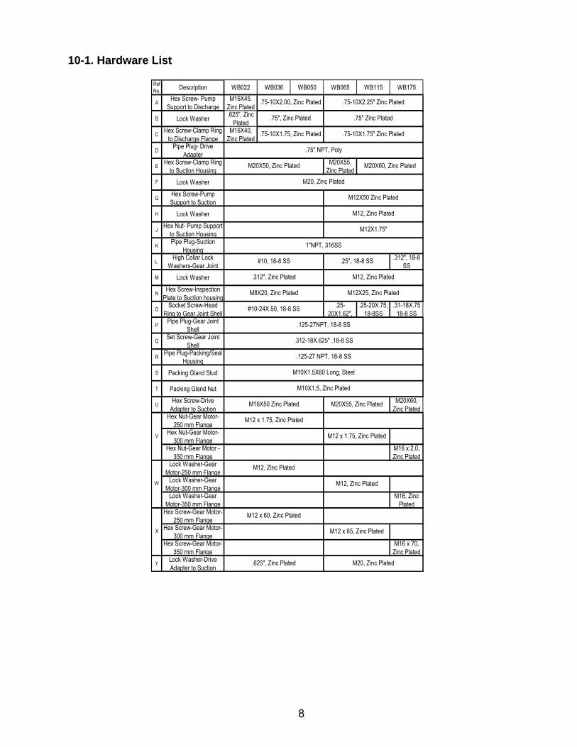
10-1. Hardware List
Ref No. Description WB022 WB036 WB050 WB065 WB115 WB175
AHex Screw- Pump
Support to Discharge M16X45,
Zinc Plated
B Lock Washer.625", Zinc
Plated
CHex Screw-Clamp Ring
to Discharge FlangeM16X40,
Zinc Plated
DPipe Plug- Drive
Adapter
EHex Screw-Clamp Ring
to Suction HousingM20X55,
Zinc Plated
F Lock Washer
GHex Screw-Pump Support to Suction
H Lock Washer
JHex Nut- Pump Support
to Suction Housing
KPipe Plug-Suction
Housing
L High Collar Lock
Washers-Gear Joint .312", 18-8
SS
M Lock Washer
NHex Screw-Inspection
Plate to Suction housing
OSocket Screw-Head
Ring to Gear Joint Shell.25-
20X1.62", .25-20X.75,
18-8SS.31-18X.75
18-8 SS
PPipe Plug-Gear Joint
Shell
QSet Screw-Gear Joint
Shell
RPipe Plug-Packing/Seal
Housing
S Packing Gland Stud
T Packing Gland Nut
UHex Screw-Drive
Adapter to Suction M20X60,
Zinc PlatedHex Nut-Gear Motor-
250 mm FlangeHex Nut-Gear Motor-
300 mm FlangeHex Nut-Gear Motor -
350 mm FlangeM16 x 2.0, Zinc Plated
Lock Washer-Gear Motor-250 mm Flange
Lock Washer-Gear Motor-300 mm Flange
Lock Washer-Gear Motor-350 mm Flange
M16, Zinc Plated
Hex Screw-Gear Motor-250 mm Flange
Hex Screw-Gear Motor-300 mm Flange
Hex Screw-Gear Motor-350 mm Flange
M16 x 70, Zinc Plated
YLock Washer-Drive Adapter to Suction
M20, Zinc Plated
M12X50 Zinc Plated
M12, Zinc Plated
M12X1.75"
.75-10X2.25" Zinc Plated
.75" Zinc Plated
.75-10X1.75" Zinc Plated
.75" NPT, Poly
.75-10X2.00, Zinc Plated
.75", Zinc Plated
.75-10X1.75, Zinc Plated
M20X60, Zinc Plated
M20X55, Zinc Plated
M12, Zinc Plated
M12X25, Zinc Plated
1"NPT, 316SS
.125-27 NPT, 18-8 SS
#10, 18-8 SS
.312", Zinc Plated
M20X50, Zinc Plated
M16X50 Zinc Plated
M12 x 1.75, Zinc Plated
M12, Zinc Plated
M12, Zinc Plated
.25", 18-8 SS
#10-24X.50, 18-8 SS
M10X1.5X60 Long, Steel
M10X1.5, Zinc Plated
.125-27NPT, 18-8 SS
.312-18X.625" ,18-8 SS
M8X20, Zinc Plated
V
M12 x 1.75, Zinc Plated
M12 x 60, Zinc Plated
M12 x 65, Zinc Plated
.625", Zinc Plated
W
X
M20, Zinc Plated
9
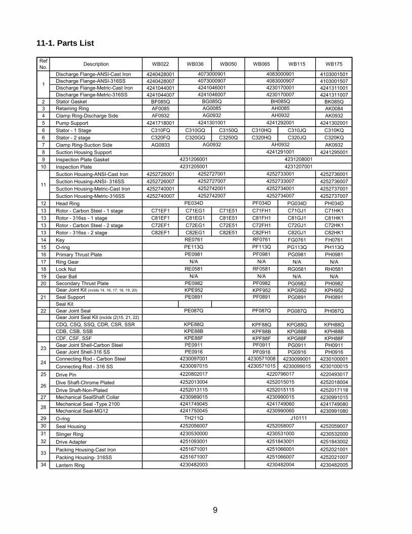
11-1. Parts List
Ref No.
Description WB022 WB036 WB050 WB065 WB115 WB175
Discharge Flange-ANSI-Cast Iron 4240428001 4103001501Discharge Flange-ANSI-316SS 4240428007 4103001507Discharge Flange-Metric-Cast Iron 4241044001 4241311001Discharge Flange-Metric-316SS 4241044007 4241311007
2 Stator Gasket BF085Q BK085Q3 Retaining Ring AF0085 AK0084
4 Clamp Ring-Discharge Side AF0932 AK0932
5 Pump Support 4241718001 4241302001
6 Stator - 1 Stage C310FQ C310GQ C3150Q C310HQ C310JQ C310KQ
6 Stator - 2 stage C320FQ C320GQ C3250Q C320HQ C320JQ C320KQ
7 Clamp Ring-Suction Side AG0933 AK0932
8 Suction Housing Support 4241295001
9 Inspection Plate Gasket
10 Inspection Plate
Suction Housing-ANSI-Cast Iron 4252726001 4252736001
Suction Housing-ANSI- 316SS 4252726007 4252736007
Suction Housing-Metric-Cast Iron 4252740001 4252737001
Suction Housing-Metric-316SS 4252740007 4252737007
12 Head Ring PG034D PH034D
13 Rotor - Carbon Steel - 1 stage C71EF1 C71EG1 C71E51 C71FH1 C71GJ1 C71HK1
13 Rotor - 316ss - 1 stage C81EF1 C81EG1 C81E51 C81FH1 C81GJ1 C81HK1
13 Rotor - Carbon Steel - 2 stage C72EF1 C72EG1 C72E51 C72FH1 C72GJ1 C72HK1
13 Rotor - 316ss - 2 stage C82EF1 C82EG1 C82E51 C82FH1 C82GJ1 C82HK1
14 Key FG0761 FH0761
15 O-ring PG113Q PH113Q
16 Primary Thrust Plate PG0981 PH0981
17 Ring Gear N/A N/A
18 Lock Nut RG0581 RH0581
19 Gear Ball N/A N/A
20 Secondary Thrust Plate PG0982 PH0982Gear Joint Kit (inclds 14, 16, 17, 18, 19, 20) KPF952 KPG952 KPH952
21 Seal Support PG0891 PH0891Seal Kit
22 Gear Joint Seal PG087Q PH087QGear Joint Seal Kit (inclds (2)15, 21, 22)
CDQ, CSQ, SSQ, CDR, CSR, SSR KPF88Q KPG88Q KPH88QCDB, CSB, SSB KPF88B KPG88B KPH88BCDF, CSF, SSF KPF88F KPG88F KPH88FGear Joint Shell-Carbon Steel PG0911 PH0911Gear Joint Shell-316 SS PF0916 PG0916 PH0916Connecting Rod - Carbon Steel 4230099001 4230100001
Connecting Rod - 316 SS 4230099015 4230100015
25 Drive Pin 4220493017
Dive Shaft-Chrome Plated 4252018004
Drive Shaft-Non-Plated 4252017118
27 Mechanical SealShaft Collar 4230991015Mechanical Seal -Type 2100 4241749080Mechanical Seal-MG12 4230991080
29 O-ring
Seal Housing 4252059007
Slinger Ring 4230532000
Drive Adapter 4251843002
Packing Housing-Cast Iron 4252021001
Packing Housing- 316SS 4252021007
Lantern Ring 4230482005
31
284241749060
4230531000
4230990060
4252056007
TH211Q
4252013004
4252013115 4252015115
4230990015
4252058007
4251843001
4230482004
4251066001
4251066007
4241292001
4241291001
AG0932
4252733001
4252742001 4252734001
4252727007 4252733007
AH0932
4073000901 4083000901
4231208001
4231207001
4231206001
4231205001
4241046001
AG0085
AH0932
4241301001
BG085Q
AG0932
BH085Q
4251671001
4230482003
RE0761
PF034D
42527340074252742007
1
11
4073000907 4083000907
4241046007 42301700074230170001
4252727001
AH0085
PF113Q
N/A
PE113Q
N/A
PE0981 PF0981
RF0761
PE034D
4220796017
4230530000
N/A N/A
PE0982 PF0982
KPE88Q
4230989015
PE0891
4230097015
42417490454241750045
KPE88BKPE88F
4251093001
34
334251671007
32
30
4230097001 423057100824
4220802017
J10111
264252015015
4230571015
RE0581
23PE0916
PF0891
PE087Q PF087Q
PE0911 PF0911
RF0581
KPE952
10
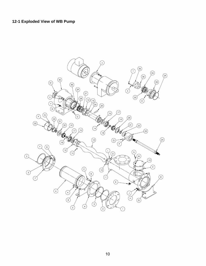
12-1 Exploded View of WB Pump
11
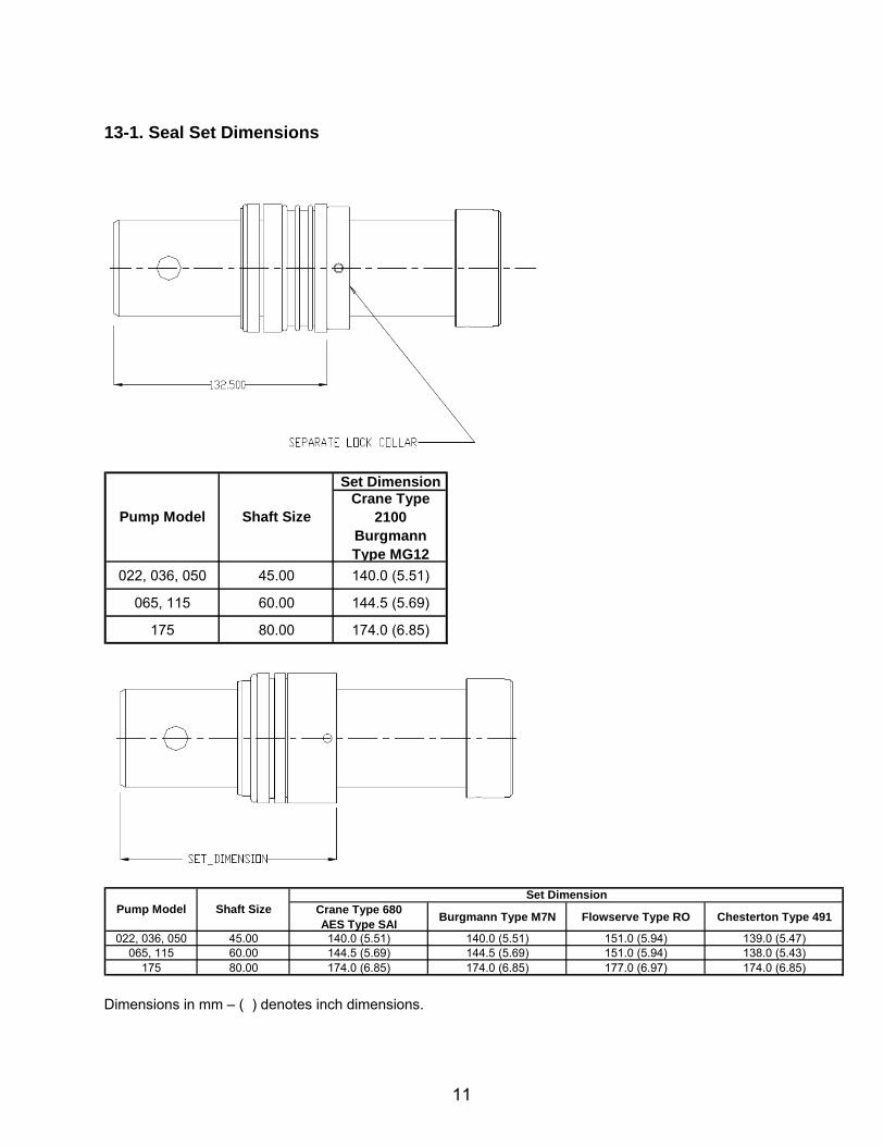
13-1. Seal Set Dimensions
Set DimensionCrane Type
2100Burgmann Type MG12
022, 036, 050 45.00 140.0 (5.51)
065, 115 60.00 144.5 (5.69)
175 80.00 174.0 (6.85)
Shaft SizePump Model
Crane Type 680AES Type SAI
Burgmann Type M7N Flowserve Type RO Chesterton Type 491
022, 036, 050 45.00 140.0 (5.51) 140.0 (5.51) 151.0 (5.94) 139.0 (5.47)065, 115 60.00 144.5 (5.69) 144.5 (5.69) 151.0 (5.94) 138.0 (5.43)
175 80.00 174.0 (6.85) 174.0 (6.85) 177.0 (6.97) 174.0 (6.85)
Set DimensionPump Model Shaft Size
Dimensions in mm – ( ) denotes inch dimensions.
12
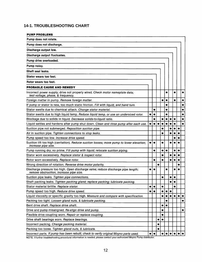
14-1. TROUBLESHOOTING CHART

©2011 by Moyno, Inc. Printed in U.S.A. ®Moyno is a registered trademark of Moyno, Inc. 0311 Moyno is part of the Fluid Management Group of Robbins & Myers, Inc. Mobil 1 is a trademark of Exxon-Mobil
Your Authorized Service Distributor is: